EP4089214A1 - Crimper and method for producing tow band - Google Patents
Crimper and method for producing tow band Download PDFInfo
- Publication number
- EP4089214A1 EP4089214A1 EP20912699.4A EP20912699A EP4089214A1 EP 4089214 A1 EP4089214 A1 EP 4089214A1 EP 20912699 A EP20912699 A EP 20912699A EP 4089214 A1 EP4089214 A1 EP 4089214A1
- Authority
- EP
- European Patent Office
- Prior art keywords
- filaments
- value
- velocity
- contact surfaces
- crimper
- Prior art date
- Legal status (The legal status is an assumption and is not a legal conclusion. Google has not performed a legal analysis and makes no representation as to the accuracy of the status listed.)
- Granted
Links
Images
Classifications
-
- D—TEXTILES; PAPER
- D02—YARNS; MECHANICAL FINISHING OF YARNS OR ROPES; WARPING OR BEAMING
- D02G—CRIMPING OR CURLING FIBRES, FILAMENTS, THREADS, OR YARNS; YARNS OR THREADS
- D02G1/00—Producing crimped or curled fibres, filaments, yarns, or threads, giving them latent characteristics
- D02G1/12—Producing crimped or curled fibres, filaments, yarns, or threads, giving them latent characteristics using stuffer boxes
Definitions
- the present disclosure relates to a crimper that crimps filaments, and a method for producing a tow band made of the crimped filaments.
- a crimper such as that disclosed in Patent Document 1 is used when producing a crimped tow band.
- This crimper includes a pair of nip rolls, a pair of plate members (chamber), and a pressing member (flapper).
- filaments are inserted between the pair of nip rolls while being conveyed and are then crimped.
- the filaments that have passed through the pair of nip rolls are conveyed while being made to meander by plate surfaces of the pair of plate members, and are pressed against one of the plate surfaces of the pair of plate members by the pressing member. As a result, the filaments are further crimped.
- Patent Document 1 JP (Translation of PCT Application) 2009-501282 T
- the crimper having the configuration described above needs to be appropriately set up to prevent the filaments being subject to, from the plate surfaces of the pair of plate members, frictional force that is excessively large relative to force (hereinafter, may be simply referred to as conveyance force) for sending the filaments toward the downstream side in a conveyance direction using the pair of nip rolls.
- conveyance force frictional force that is excessively large relative to force
- a tow band that is uniformly crimped may be difficult to produce stably.
- the pressure drop (PD) of a cigarette filter produced using this tow band will vary, whereby the quality of the cigarette filter will decrease.
- an object of the present disclosure is to enable stable production of uniformly crimped tow bands.
- a crimper includes: a pair of nip rolls including respective peripheral surfaces between which conveyed filaments pass; a first member and a second member including respective contact surfaces that come into contact with the filaments and being disposed on a downstream side of the pair of nip rolls in a conveyance direction of the filaments, the contact surfaces being disposed facing each other across a gap; and a pressing member disposed in the gap and configured to press the filaments toward the contact surface of any of the first member and the second member.
- a surface roughness Ra of the contact surfaces of the pressing member is set to a value in a range of from 0.1 to 1.0.
- the surface roughness Ra of the contact surfaces of the first member and the second member is set to a value in the range of from 0.1 to 1.0.
- the frictional force applied to the filaments by the pair of contact surfaces is adjusted to a value that is not excessively large with respect to the conveyance force applied to the filaments by the pair of nip rolls, and thus the filaments can be more uniformly crimped by the crimper.
- the uniformly crimped tow band can be stably produced.
- the Rockwell hardness HRC of the first member and the second member may be set to a value in a range of from 50 to 60. Furthermore, the Vickers hardness HV of the first member and the second member may be set to a value of 350 or greater. Since the types of hardness of the first member and the second member are set to values in the appropriate ranges, wear of the contact surfaces can be suppressed. This makes it possible to stably crimp the filaments.
- At least one of the first member or the second member may include a substrate having a flat plate shape and a coating film that covers a surface of the substrate and is harder than the substrate, the coating film including the contact surface that is positioned on an opposite side of the coating film from the substrate.
- the coating film may be a chromium nitride film.
- a coefficient of kinetic friction between the contact surfaces and the filaments may be set to a value in a range of from 0.1 to 0.5.
- the frictional force applied to the filaments by the pair of contact surfaces is easily adjusted to a value that is not excessively large with respect to the conveyance force applied to the filaments by the pair of nip rolls. This makes it possible to further stabilize the crimping of the filaments.
- a velocity CV, represented by Equation 1, of the filaments conveyed in the gap may be set to a value between 0% and 100%:
- Velocity CV % ⁇ / Vm ⁇ 100 , where Vm is an average velocity value that is an average of measured values of a velocity of the filaments immediately before the velocity of the filaments is shifted from acceleration to deceleration within a unit time and of a velocity of the filaments immediately before the velocity is shifted from deceleration to acceleration within the unit time, and ⁇ is a standard deviation of the measured values.
- the crimper can efficiently and easily crimp the filaments uniformly.
- the content of titanium oxide in the filaments may be set to a value in a range of from 0 wt.% to 0.1 wt.%.
- the crimper can easily crimp the filaments uniformly even when the amount of titanium oxide is set to a value in the range described above.
- a method for producing a tow band includes a step, the step including: causing conveyed filaments to pass between respective peripheral surfaces of a pair of nip rolls; introducing the filaments having passed between the pair of nip rolls into a gap between a first member and a second member disposed on a downstream side of the pair of nip rolls in a conveyance direction of the filaments and having respective contact surfaces disposed facing each other across the gap; and pressing the filaments toward the contact surface of any of the first member and the second member using a pressing member disposed in the gap, in which, in the step, the first member and the second member used have a surface roughness Ra of the contact surfaces set to a value in a range of from 0.1 to 1.0.
- the frictional force applied to the filaments by the pair of contact surfaces can be adjusted to a value that is not excessively large with respect to the conveyance force applied to the filaments by the pair of nip rolls. This makes it possible to uniformly crimp the filaments. As a result, a uniformly crimped tow band can be stably produced.
- the first member and the second member having a Rockwell hardness HRC set to a value in a range of from 50 to 60 may be used.
- the first member and the second member having a Vickers hardness HV set to a value of 350 or greater may be used.
- the first member or the second member including a substrate having a flat plate shape and a coating film that covers a surface of the substrate and is harder than the substrate may be used, and the coating film including the contact surface that is positioned on an opposite side of the coating film from the substrate.
- the first member and the second member in which the coating films are chromium nitride films may be used.
- the first member and the second member used having a coefficient of kinetic friction between the contact surfaces and the filaments set to a value in a range of from 0.1 to 0.5 may be used.
- the frictional force applied to the filaments by the pair of contact surfaces is more easily adjusted to a value that is not excessively large with respect to the conveyance force applied to the filaments by the pair of nip rolls. This makes it possible to more stably crimp the filaments.
- a velocity CV, represented by Equation 1, of the filaments conveyed in the gap may be set to a value between 0% and 100%:
- Velocity CV % ⁇ / Vm ⁇ 100 , where Vm is an average velocity value that is an average of measured values of a velocity of the filaments immediately before the velocity of the filaments is shifted from acceleration to deceleration within a unit time and of a velocity of the filaments immediately before the velocity is shifted from deceleration to acceleration within the unit time, and ⁇ is a standard deviation of the measured values.
- the filaments are conveyed at a stable velocity in the gap, and thus the filaments can be efficiently and easily crimped uniformly.
- the filaments having a content of titanium oxide set to a value from 0 wt.% to 0.1 wt.% may be used.
- the filaments can be easily crimped uniformly even when the amount of titanium oxide is set to a value in the range described above.
- a uniformly crimped tow band can be stably produced.
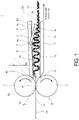
- FIG. 1 is a schematic view of a crimper 1 according to an embodiment.
- the crimper 1 crimps a plurality of filaments 11 to be conveyed.
- the content of titanium oxide in the filaments 11 of the present embodiment is set to a value in a range of from 0 wt.% to 0.1 wt.% as an example. That is, the filaments 11 of the present embodiment have a very low content of titanium oxide, or do not contain any titanium oxide.
- the plurality of filaments 11 are introduced to the crimper 1 on the upstream side of the crimper 1 in a state where water has been applied to the filaments 11.
- the crimper 1 includes a pair of nip rolls 2 and 3 (first nip roll 2 and second nip roll 3), a chamber (stuffing box) 4, and a pressing member 5.
- the pair of nip rolls 2 and 3 are axially supported with the respective peripheral surfaces facing each other in one direction (here, the vertical direction) perpendicular to the conveyance direction of the yarn bundle 10 to be conveyed.
- the pair of nip rolls 2 and 3 are rotated inversely to each other.
- a gap G1 between the pair of nip rolls 2 and 3 is adjusted by pressing the nip roll 2 toward the nip roll 3 using a pressing device (not illustrated).
- the pair of nip rolls 2 and 3 cause the yarn bundle 10 to pass between their peripheral surfaces and crimp the yarn bundle 10.
- the yarn bundle 10 is nipped at a nip point N of the pair of nip rolls 2 and 3 with the plurality of filaments 11 arranged in a flat band shape along the axial directions of the pair of nip rolls 2 and 3.
- the plurality of filaments 11 constituting the yarn bundle 10 are primarily crimped.
- the material of the nip rolls 2 and 3 can be selected as appropriate.
- Examples of the material of the peripheral surface of the nip rolls 2 and 3 include SACM (aluminum-chromium-molybdenum steel).
- SACM aluminum-chromium-molybdenum steel.
- the nip rolls 2 and 3 have a hard coating film formed on their peripheral surfaces.
- the chamber 4 is disposed downstream of the pair of nip rolls 2 and 3 in the conveyance direction.
- the chamber 4 includes a first member 6 and a second member 7.
- the first member 6 and the second member 7 have contact surfaces 6a and 7a, respectively, that are in contact with the filaments 11.
- the contact surfaces 6a and 7a are disposed facing each other across a gap.
- the first member 6 and the second member 7 have a long flat plate shape, for example, and extend in the conveyance direction of the yarn bundle 10 that has passed between the peripheral surfaces of the pair of nip rolls 2 and 3. At this time, the width direction of the first member 6 and the second member 7 are aligned with the axial direction of the pair of nip rolls 2 and 3.
- the coefficient of kinetic friction between the contact surfaces 6a and 7a and the filaments 11 is set to a value in a range of from 0.1 to 0.5.
- the coefficient of kinetic friction can be adjusted by, for example, changing the surface shapes of the contact surfaces 6a and 7a.
- the coefficient of kinetic friction decreases as the surface shapes of the contact surfaces 6a and 7a become smoother, and increases as the surface shapes become rougher in a certain range, for example.
- the first member 6 and the second member 7 of the present embodiment are plate members.
- the contact surfaces 6a and 7a are plate surfaces of the first member 6 and the second member 7, respectively.
- the material of the members 6 and 7 can be set as appropriate.
- the members 6 and 7 have substrates 6c and 7c each having a flat plate shape and coating films 6d and 7d that each cover the surfaces of the substrates 6c and 7c and are harder than the substrates 6c and 7c, respectively.
- the coating films 6d and 7d are disposed facing each other.
- the contact surfaces 6a and 7a are surfaces that are positioned on opposite sides of the coating films 6d and 7d from the substrates 6c and 7c, respectively.
- the thickness dimension of the coating films 6d and 7d can be set as appropriate, and for example, can be set to a value in a range of from several micrometers to several tens of micrometers. Note that at least one of the first member 6 or the second member 7 is not necessarily a plate member.
- Examples of the material of the substrates 6c and 7c include beryllium copper (BeCu) (C1720(T) and the like), stainless steel (SUS304 (austenitic stainless steel)), SUS440C (martensitic stainless steel), and the like), and ceramic.
- Examples of the material of the coating films 6d and 7d include chromium nitride.
- the substrates 6c and 7c are made of SUS440C.
- the coating films 6d and 7d are chromium nitride films.
- An upstream end 6b of the first member 6 in the conveyance direction is close to the peripheral surface of the first nip roll 2.
- the contact surface 6a of the first member 6 is disposed away from the contact surface 7a of the second member 7 while inclining at an inclination angle ⁇ with respect to the contact surface 7a from the end 6b of the first member 6 toward the other end of the first member 6.
- An upstream end 7b of the second member 7 in the conveyance direction is close to the peripheral surface of the second nip roll 3.
- a gap G2 between the ends 6b and 7b is the shortest gap between the members 6 and 7, and can be set as appropriate.
- the pressing member 5 is disposed in the gap between the members 6 and 7, and presses the filaments 11 toward the contact surfaces 6a and 7a of either of the members 6 and 7.
- the pressing member 5 is a plate member that extends in the axial direction of the pair of nip rolls 2 and 3.
- the pressing member 5 is axially supported by the first member 6 in a state where an upstream end 5a of the pressing member 5 can turn in the conveyance direction about a rotation axis P.
- the pressing member 5 is biased by a biasing member (not illustrated) having an elastic body such as a spring.
- the pressing member 5 presses the yarn bundle 10 against the contact surface 7a in the direction from the first member 6 toward the second member 7 at a downstream end 5b of the pressing member 5 in the conveyance direction.
- the yarn bundle 10 After passing between the pair of nip rolls 2 and 3, the yarn bundle 10 is pressed into the chamber 4. In the crimper 1, the yarn bundle 10 is highly crimped as the yarn bundle 10 moves toward the downstream side in the conveyance direction while meandering between the members 6 and 7 and pressed by the pressing member 5 against the contact surface 7a. The conveyance velocity of the yarn bundle 10 when conveyed in the chamber 4 varies. As illustrated in FIG. 1 , after the yarn bundle 10 passes through the crimper 1, the yarn bundle 10 becomes a crimped tow band 12.
- a surface roughness Ra of the contact surfaces 6a and 7a of the members 6 and 7 is set to a value in a range of from 0.1 to 1.0.
- the surface roughness Ra herein is a center-line average surface roughness Ra, and is a value calculated by the method according to JIS B 0601 (1994) using the high precision shape measurement system KS-1100 (available from Keyence Corporation).
- the frictional force applied to the filaments 11 by the contact surfaces 6a and 7a is set to a value in an appropriate range.
- the difference between the conveyance force applied to the filaments 11 by the pair of nip rolls 2 and 3 and the frictional force applied to the filaments 11 by the contact surfaces 6a and 7a is adjusted to a certain value that is not excessively small.
- the conveyance velocity of the yarn bundle 10 (filaments 11) conveyed in the chamber 4 is stabilized, and a tow band 12 in which the filaments 11 are uniformly crimped by the crimper 1 can be obtained.
- the value of the surface roughness Ra of the contact surfaces 6a and 7a in the above range is preferably set depending on the type of the tow band 12 to be produced (for example, the total denier (TD) of the tow band 12, the filament denier (FD) of the filaments 11, the cross-sectional shape of the filaments 11, and the composition of the filaments 11 such as the content of titanium oxide).
- the surface shape of the contact surfaces 6a and 7a can be formed by known methods including various blasting methods such as sandblasting and methods using discharge machining.
- the Rockwell hardness HRC of the members 6 and 7 (value obtained by a Rockwell hardness HRC test using the C scale according to JIS Z2245 (2011)) is set to a value in a range of from 50 to 60. Furthermore, the Vickers hardness HV of the members 6 and 7 (value obtained by a Vickers hardness test according to JIS Z2244 (2009)) is set to a value of 350 or greater.
- the surface shape of the contact surfaces 6a and 7a with the surface roughness Ra set to the value described above can be stably retained over a long period of time.
- the wear of the contact surfaces 6a and 7a of the members 6 and 7 can be suppressed over a long period of time. Furthermore, by setting the thickness dimension of the coating films 6d and 7d to the value described above, the coating films 6d and 7d can suppress wear of the contact surfaces 6a and 7a, and the characteristics of the substrates 6c and 7c can be easily exhibited.
- a velocity CV, represented by Equation 1 of the filaments 11 conveyed in the gap between the members 6 and 7 is set to a value between 0% and 100%.
- Velocity CV % ⁇ / Vm ⁇ 100 where Vm is an average velocity value that is an average of the measured values of the velocity of the filaments 11 immediately before the velocity of the filaments 11 is shifted from acceleration to deceleration within a unit time and of the velocity of the filaments 11 immediately before the velocity is shifted from deceleration to acceleration within the unit time, and ⁇ is the standard deviation of the measured values.
- the unit time can be set as appropriate, and is 1 second, for example.
- the velocity CV represented by Equation 1 is defined as a variation in the velocity of the filaments 11 passing between the members 6 and 7 in the conveyance direction.
- the velocity CV exceeds 100%, the conveyance velocity of the filaments 11 in the chamber 4 varies significantly.
- excessive tension can act from the crimper 1 on the filaments 11 conveyed from each of the cabinets when the filaments 11 are crimped by the crimper 1 on the downstream side of the cabinets in the conveyance direction, and thus the filaments 11 conveyed from all the cabinets may be cut.
- the crimper 1 of the present embodiment by setting the velocity CV to 100% or less, excessive tension is prevented from acting on the filaments 11.
- the conveyed filaments 11 are stably and uniformly crimped by the crimper 1.
- the velocity CV is preferably a value in a range of from 0% to 80%, more preferably a value in a range of from 0% to 70%, and still more preferably a value in a range of from 0% to 60%.
- the velocity CV is a value that can be measured using the crimper 1, which is the machine actually used for producing the tow band 12.
- the method for adjusting the crimper 1 to appropriately crimp the filaments 11 based on the measured velocity CV is more advantageous than a method for adjusting a crimper, being the actual machine used, by using a test crimper with specifications different from those of the actual crimper to examine the behavior of the filaments 11 in the test crimper, for example, because accurate adjustment of the crimping machine 1 can be made more directly and quickly.
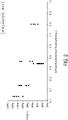
- FIG. 2 is a graph showing a relationship between the surface roughness Ra of the contact surfaces 6a and 7a of the first member 6 and the second member 7 and the velocity CV of the yarn bundle 10 in the chamber 4.
- measured data is plotted for a crimper 1 in which the material of the members 6 and 7 is beryllium copper (hereinafter referred to as a crimper A), and a crimper 1 in which the material of the members 6 and 7 is SUS440C (hereinafter referred to as a crimper B).
- the graph depicts results of measuring the velocity CV of the crimpers A and B multiple times when the surface roughness Ra of the contact surfaces 6a and 7a was set to a specific value.
- the average value of the velocity CV was a value close to 100% when the surface roughness Ra of the contact surfaces 6a and 7a was about 0.14, and that the average value of the velocity CV was about 95% when the surface roughness Ra of the contact surfaces 6a and 7a was about 4.6.
- the velocity CV is assumed to slowly decrease as the surface roughness Ra of the contact surfaces 6a and 7a increases, with the surface roughness Ra of the contact surfaces 6a and 7a falling within the range of from 0.14 to 4.6.
- the average value of the velocity CV was a value close to 100% when the surface roughness Ra of the contact surfaces 6a and 7a was about 0.24, and that the average value of the velocity CV was about 65% when the surface roughness Ra of the contact surfaces 6a and 7a was about 0.44.
- the velocity CV is assumed to slowly decrease as the surface roughness Ra of the contact surfaces 6a and 7a increases, with the surface roughness Ra of the contact surfaces 6a and 7a falling within the range of from 0.24 to 0.44.
- the average value of the velocity CV was 75% when the surface roughness Ra of the contact surfaces 6a and 7a was 0.8.
- the average value of the velocity CV of the crimper B does not exceed about 100%, at least when the surface roughness Ra of the contact surfaces 6a and 7a falls within the range of from 0.15 to 0.9.
- the surface roughness Ra of the contact surfaces 6a and 7a is more preferably a value in a range of from 0.15 to 0.9, still more preferably a value in a range of from 0.3 to 0.8, and yet more preferably a value in a range of from 0.4 to 0.75.
- the surface roughness Ra of the contact surfaces 6a and 7a is preferably a value in a range of from 0.2 to 0.9.
- the lower limit value of the surface roughness Ra of the contact surfaces 6a and 7a is preferably any of 0.1, 0.15, 0.2, 0.3, or 0.4
- the upper limit value of the surface roughness Ra of the contact surfaces 6a and 7a is preferably any of 0.75, 0.8, 0.9, or 1.0.
- the surface roughness Ra of the contact surfaces 6a and 7a of the members 6 and 7 is set to a value in the range of from 0.1 to 1.0.
- the frictional force applied to the filaments 11 by the pair of contact surfaces 6a and 7a is adjusted to a value that is not excessively large with respect to the conveyance force applied to the filaments 11 by the pair of nip rolls 2 and 3, and thus the filaments 11 can be more uniformly crimped by the crimper 1.
- a uniformly crimped tow band 12 can be stably produced.
- the Rockwell hardness HRC of the first member 6 and the second member 7 is set to a value in a range of from 50 to 60. Furthermore, the Vickers hardness HV of the first member 6 and the second member 7 is set to a value of 350 or greater.
- the types of hardness of the members 6 and 7 are set to values in the appropriate ranges, wear of the contact surfaces 6a and 7a can be suppressed. As a result, the filaments 11 can be stably crimped. Furthermore, when the Rockwell hardness HRC of the members 6 and 7 is kept to 60 or less, the members 6 and 7 are easily produced.
- At least one of the first member 6 or the second member 7 includes the flat plate-like substrates 6c and 7c and the coating films 6d and 7d that cover the surfaces of the substrates 6c and 7c and are harder than the substrates 6c and 7c, the coating film 6d and 7d including the contact surfaces 6a and 7a are positioned on opposite sides of the coating film 6d and 7d from the substrates 6c and 7c.
- the coating films 6d and 7d are chromium nitride films as an example.
- the coefficient of kinetic friction between the contact surfaces 6a and 7a of the members 6 and 7 and the filaments 11 is set to a value in a range of from 0.1 to 0.5.
- the frictional force applied to the filaments 11 by the pair of contact surfaces 6a and 7a is easily adjusted to a value that is not excessively large with respect to the conveyance force applied to the filaments 11 by the pair of nip rolls 2 and 3. This makes it possible to further stabilize the crimping of the filaments 11.
- the velocity CV, represented by Equation 1 of the filaments 11 conveyed along the gap between the members 6 and 7 is set to a value between 0% and 100%.
- the content of titanium oxide in the filaments 11 is set to a value in a range of from 0 wt.% to 0.1 wt.%.
- the crimper 1 can easily crimp the filaments 11 uniformly even when the amount of titanium oxide in the filaments 11 is set to a value in the range described above.
- a method for producing the tow band 12 according to one aspect of the present disclosure includes a step using the crimper 1. That is, this production method includes a step, the step including: causing the filaments 11 that are conveyed to pass between the peripheral surfaces of the pair of nip rolls 2 and 3, introducing the filaments 11 having passed between the pair of nip rolls 2 and 3 into the gap between the first member 6 and the second member 7 disposed on the downstream side of the pair of nip rolls 2 and 3 in the conveyance direction of the filaments 11 and having the respective contact surfaces 6a and 7a disposed facing each other across the gap, and pressing the filaments 11 toward the contact surface of any of the members 6 and 7 using the pressing member 5 disposed in the gap.
- the first member 6 and the second member 7 having a Rockwell hardness HRC set to a value in a range of from 50 to 60 are used.
- the first member 6 and the second member 7 having a Vickers hardness HV set to a value of 350 or greater are used.
- at least one of the first member 6 or the second member 7 (here, both of them) including the substrates 6c and 7c and the coating films 6d and 7d is used, and the coating films 6d and 7d including contact surfaces 6a and 7a that are positioned on opposite sides of the coating film 6d and 7d from the substrates 6c and 7.
- the members 6 and 7 in which the contact surfaces 6a and 7a have chromium nitride films are used.
- the frictional force applied to the filaments 11 by the pair of contact surfaces 6a and 7a can be adjusted to a value that is not excessively large with respect to the conveyance force applied to the filaments 11 by the pair of nip rolls 2 and 3.
- This makes it possible to uniformly crimp the filaments 11.
- a uniformly crimped tow band 12 can be stably produced.
- the members 6 and 7 having a coefficient of kinetic friction between the contact surfaces 6a and 7a and the filaments 11 set to a value in a range of from 0.1 to 0.5 are used.
- the frictional force applied to the filaments 11 by the pair of contact surfaces 6a and 7a is more easily adjusted to a value that is not excessively large with respect to the conveyance force applied to the filaments 11 by the pair of nip rolls 2 and 3. This makes it easy to crimp the filaments 11 more stably.
- the velocity CV, represented by Equation 1 of the filaments 11 conveyed in the gap between the members 6 and 7 is set to a value between 0% and 100%.
- the filaments 11 having a content of titanium oxide set to a value from 0 wt.% to 0.1 wt.% are used.
- the filaments 11 can be easily crimped uniformly even when the amount of titanium oxide in the filaments 11 is set to a value in the range described above.
- the crimpers 1 of Examples 1 to 7 were driven under the same driving condition to produce tow bands 12. Under this condition, based on Equation 1, the velocity CV was measured for each crimper 1 using a high-velocity camera capable of capturing images of the yarn bundle 10 conveyed in the chamber 4. The unit time was set to 1 second.
- Filaments 11 having a Y-shaped cross-section with the FD set to 6.0 were used as the filaments 11 used for producing the tow band 12.
- the TD of the tow band 12 was set to 17000.
- cylindrical plugs (length dimension: 120 mm, circumferential length: 24.4 mm) were produced as semi-products immediately before producing (cutting out) cigarette filters with a predetermined length dimension.
- the pressure drop of each of the plugs produced by the crimpers 1 of Examples 1 to 7 and a value (PDCV) of variation in the standard deviation of the pressure drop of the plugs were examined.
- the pressure drop was calculated with the tow weights and the plug circumference of the plugs corrected to be uniform.
- 15 plugs of each of Examples 1 to 7 were grouped as a single set, and a CV value indicating a variation in the pressure drop of each of the single set of plugs was calculated.
- the PDCV was calculated as the average value of the CV values obtained from 10 sets.
- the tow band 12 was produced using the crimper 1 of Example 4. A plug was produced using this tow band 12, and the pressure drop and PDCV of the plug was calculated by the method described above.
- Example 6 achieves a PDCV even smaller than that achieved by the plug produced by the crimper 1 of Example 4. Furthermore, it was found that the performance of Example 6 was maintained after operating the crimper 1 of Example 6 for at least 90 days. Supposedly, this is due to the coating films 6d and 7d made of chromium nitride films formed on the members 6 and 7, leading to improved wear resistance of the contact surfaces 6a and 7a of the members 6 and 7 and ensuring that the surface shape of the contact surfaces 6a and 7a is maintained over a long period of time.
- the Rockwell hardness HRC of the members 6 and 7 is preferably set to a value in a range of from 13 to 104, for example.
- the Rockwell hardness HRC of the members 6 and 7 is more preferably set to a value in a range of from 50 to 60, for example.
- the lower limit value and the upper limit value of the Rockwell hardness HRC of the members 6 and 7 are preferably any of 13, 40, and 56 and any of 65, 104, and 106, respectively, for example.
- the Vickers hardness HV of the members 6 and 7 is preferably set to a value in a range of from 187 to 2500, for example.
- the Vickers hardness HV of the members 6 and 7 is more preferably set to a value of 350 or greater (with an upper limit value of 2500 or less as an example), for example.
- the lower limit value and the upper limit value of the Vickers hardness HV of the members 6 and 7 are preferably any of 187, 400, and 619 and any of 800, 2200, 2400, and 2500, respectively, for example.
- the filaments 11 of the yarn bundle 10 may contain titanium oxide exceeding 0.1 wt.% (set to a value in a range of from 0.3 wt.% to 0.4 wt.%, for example).
- the surface of the pressing member 5 that comes into contact with at least the filaments 11 may have a surface roughness that is similar to the surface roughness Ra of the contact surfaces 6a and 7a.
- the coating films 6d and 7d may be locally disposed in regions of the members 6 and 7 that come into contact with the filaments 11.
- the Rockwell hardness HRC of the members 6 and 7 may be set to a value exceeding 60.
- the tow band 12 may also be used in articles other than cigarette filters (an absorbent article or a filtration member, for example).
- filaments can be advantageously crimped uniformly. Therefore, it is useful to apply the present disclosure widely to crimpers and methods for producing tow bands that can achieve the significance of this advantage.
Landscapes
- Engineering & Computer Science (AREA)
- Mechanical Engineering (AREA)
- Textile Engineering (AREA)
- Yarns And Mechanical Finishing Of Yarns Or Ropes (AREA)
Abstract
Description
- The present disclosure relates to a crimper that crimps filaments, and a method for producing a tow band made of the crimped filaments.
- A crimper such as that disclosed in
Patent Document 1 is used when producing a crimped tow band. This crimper includes a pair of nip rolls, a pair of plate members (chamber), and a pressing member (flapper). In the crimper, filaments are inserted between the pair of nip rolls while being conveyed and are then crimped. The filaments that have passed through the pair of nip rolls are conveyed while being made to meander by plate surfaces of the pair of plate members, and are pressed against one of the plate surfaces of the pair of plate members by the pressing member. As a result, the filaments are further crimped. - Patent Document 1:
JP (Translation of PCT Application) 2009-501282 T - The crimper having the configuration described above needs to be appropriately set up to prevent the filaments being subject to, from the plate surfaces of the pair of plate members, frictional force that is excessively large relative to force (hereinafter, may be simply referred to as conveyance force) for sending the filaments toward the downstream side in a conveyance direction using the pair of nip rolls. When such set up is inappropriate, a tow band that is uniformly crimped may be difficult to produce stably. When the crimping of a tow band is not uniform, for example, the pressure drop (PD) of a cigarette filter produced using this tow band will vary, whereby the quality of the cigarette filter will decrease.
- In view of the above, an object of the present disclosure is to enable stable production of uniformly crimped tow bands.
- To solve the problems described above, a crimper according to one aspect of the present disclosure includes: a pair of nip rolls including respective peripheral surfaces between which conveyed filaments pass; a first member and a second member including respective contact surfaces that come into contact with the filaments and being disposed on a downstream side of the pair of nip rolls in a conveyance direction of the filaments, the contact surfaces being disposed facing each other across a gap; and a pressing member disposed in the gap and configured to press the filaments toward the contact surface of any of the first member and the second member. In the crimper according to one aspect of the present disclosure, a surface roughness Ra of the contact surfaces of the pressing member is set to a value in a range of from 0.1 to 1.0.
- With the configuration described above, the surface roughness Ra of the contact surfaces of the first member and the second member is set to a value in the range of from 0.1 to 1.0. Thus, the frictional force applied to the filaments by the pair of contact surfaces is adjusted to a value that is not excessively large with respect to the conveyance force applied to the filaments by the pair of nip rolls, and thus the filaments can be more uniformly crimped by the crimper. As a result, the uniformly crimped tow band can be stably produced.
- The Rockwell hardness HRC of the first member and the second member may be set to a value in a range of from 50 to 60. Furthermore, the Vickers hardness HV of the first member and the second member may be set to a value of 350 or greater. Since the types of hardness of the first member and the second member are set to values in the appropriate ranges, wear of the contact surfaces can be suppressed. This makes it possible to stably crimp the filaments.
- At least one of the first member or the second member may include a substrate having a flat plate shape and a coating film that covers a surface of the substrate and is harder than the substrate, the coating film including the contact surface that is positioned on an opposite side of the coating film from the substrate. In this case, the coating film may be a chromium nitride film. By using a member including the substrate and the coating film, the wear of the contact surfaces of the first member and the second member can be suppressed over a long period of time.
- A coefficient of kinetic friction between the contact surfaces and the filaments may be set to a value in a range of from 0.1 to 0.5. Thus, the frictional force applied to the filaments by the pair of contact surfaces is easily adjusted to a value that is not excessively large with respect to the conveyance force applied to the filaments by the pair of nip rolls. This makes it possible to further stabilize the crimping of the filaments.
- A velocity CV, represented by
Equation 1, of the filaments conveyed in the gap may be set to a value between 0% and 100%:
- With this configuration, since the filaments are conveyed at a stable velocity inside the crimper, the crimper can efficiently and easily crimp the filaments uniformly.
- The content of titanium oxide in the filaments may be set to a value in a range of from 0 wt.% to 0.1 wt.%. The crimper can easily crimp the filaments uniformly even when the amount of titanium oxide is set to a value in the range described above.
- A method for producing a tow band according to one aspect of the present disclosure includes a step, the step including: causing conveyed filaments to pass between respective peripheral surfaces of a pair of nip rolls; introducing the filaments having passed between the pair of nip rolls into a gap between a first member and a second member disposed on a downstream side of the pair of nip rolls in a conveyance direction of the filaments and having respective contact surfaces disposed facing each other across the gap; and pressing the filaments toward the contact surface of any of the first member and the second member using a pressing member disposed in the gap, in which, in the step, the first member and the second member used have a surface roughness Ra of the contact surfaces set to a value in a range of from 0.1 to 1.0.
- With the production method described above, by setting the surface roughness Ra of the contact surfaces of the first member and the second member to a value in the range of from 0.1 to 1.0, the frictional force applied to the filaments by the pair of contact surfaces can be adjusted to a value that is not excessively large with respect to the conveyance force applied to the filaments by the pair of nip rolls. This makes it possible to uniformly crimp the filaments. As a result, a uniformly crimped tow band can be stably produced.
- In the step described above, the first member and the second member having a Rockwell hardness HRC set to a value in a range of from 50 to 60 may be used. In the step described above, the first member and the second member having a Vickers hardness HV set to a value of 350 or greater may be used. With each of these production methods, the hardness of the contact surfaces of the first member and the second member can be set to a value in an appropriate range, and thus the wear of the contact surfaces can be suppressed. This makes it possible to stably crimp the filaments.
- In the step described above, at least one of the first member or the second member including a substrate having a flat plate shape and a coating film that covers a surface of the substrate and is harder than the substrate may be used, and the coating film including the contact surface that is positioned on an opposite side of the coating film from the substrate. In this case, in the step described above, the first member and the second member in which the coating films are chromium nitride films may be used. By using such members including the substrates and the coating films, the wear of the contact surfaces of the first member and the second member can be suppressed over a long period of time.
- In the step described above, the first member and the second member used having a coefficient of kinetic friction between the contact surfaces and the filaments set to a value in a range of from 0.1 to 0.5 may be used. Thus, the frictional force applied to the filaments by the pair of contact surfaces is more easily adjusted to a value that is not excessively large with respect to the conveyance force applied to the filaments by the pair of nip rolls. This makes it possible to more stably crimp the filaments.
- In the step described above, a velocity CV, represented by
Equation 1, of the filaments conveyed in the gap may be set to a value between 0% and 100%:
- With this method, the filaments are conveyed at a stable velocity in the gap, and thus the filaments can be efficiently and easily crimped uniformly.
- In the step described above, the filaments having a content of titanium oxide set to a value from 0 wt.% to 0.1 wt.% may be used. The filaments can be easily crimped uniformly even when the amount of titanium oxide is set to a value in the range described above.
- According to the aspects of the present disclosure, a uniformly crimped tow band can be stably produced.
-
-
FIG. 1 is a schematic view of a crimper according to an embodiment. -
FIG. 2 is a graph showing a relationship between the surface roughness Ra of contact surfaces of a first member and a second member and a velocity CV of a yarn bundle in a chamber. - An embodiment will be described below with reference to the drawings. The term "conveyance direction" hereinafter refers to the conveyance direction of a yarn bundle (a bundle of a plurality of filaments 11) 10.
-
FIG. 1 is a schematic view of acrimper 1 according to an embodiment. Thecrimper 1 crimps a plurality offilaments 11 to be conveyed. The content of titanium oxide in thefilaments 11 of the present embodiment is set to a value in a range of from 0 wt.% to 0.1 wt.% as an example. That is, thefilaments 11 of the present embodiment have a very low content of titanium oxide, or do not contain any titanium oxide. The plurality offilaments 11 are introduced to thecrimper 1 on the upstream side of thecrimper 1 in a state where water has been applied to thefilaments 11. - As illustrated in
FIG. 1 , thecrimper 1 includes a pair of nip rolls 2 and 3 (first niproll 2 and second nip roll 3), a chamber (stuffing box) 4, and apressing member 5. As illustrated inFIG. 1 , the pair of nip rolls 2 and 3 are axially supported with the respective peripheral surfaces facing each other in one direction (here, the vertical direction) perpendicular to the conveyance direction of theyarn bundle 10 to be conveyed. The pair of nip rolls 2 and 3 are rotated inversely to each other. A gap G1 between the pair of nip rolls 2 and 3 is adjusted by pressing thenip roll 2 toward thenip roll 3 using a pressing device (not illustrated). - The pair of nip rolls 2 and 3 cause the
yarn bundle 10 to pass between their peripheral surfaces and crimp theyarn bundle 10. Theyarn bundle 10 is nipped at a nip point N of the pair of nip rolls 2 and 3 with the plurality offilaments 11 arranged in a flat band shape along the axial directions of the pair of nip rolls 2 and 3. As a result, the plurality offilaments 11 constituting theyarn bundle 10 are primarily crimped. - The material of the nip rolls 2 and 3 can be selected as appropriate. Examples of the material of the peripheral surface of the nip rolls 2 and 3 include SACM (aluminum-chromium-molybdenum steel). The nip rolls 2 and 3 have a hard coating film formed on their peripheral surfaces.
- The chamber 4 is disposed downstream of the pair of nip rolls 2 and 3 in the conveyance direction. The chamber 4 includes a
first member 6 and asecond member 7. Thefirst member 6 and thesecond member 7 havecontact surfaces filaments 11. The contact surfaces 6a and 7a are disposed facing each other across a gap. - Specifically, the
first member 6 and thesecond member 7 have a long flat plate shape, for example, and extend in the conveyance direction of theyarn bundle 10 that has passed between the peripheral surfaces of the pair of nip rolls 2 and 3. At this time, the width direction of thefirst member 6 and thesecond member 7 are aligned with the axial direction of the pair of nip rolls 2 and 3. The coefficient of kinetic friction between the contact surfaces 6a and 7a and thefilaments 11 is set to a value in a range of from 0.1 to 0.5. The coefficient of kinetic friction can be adjusted by, for example, changing the surface shapes of the contact surfaces 6a and 7a. The coefficient of kinetic friction decreases as the surface shapes of the contact surfaces 6a and 7a become smoother, and increases as the surface shapes become rougher in a certain range, for example. - The
first member 6 and thesecond member 7 of the present embodiment are plate members. The contact surfaces 6a and 7a are plate surfaces of thefirst member 6 and thesecond member 7, respectively. The material of themembers members substrates coating films substrates substrates coating films coating films substrates coating films first member 6 or thesecond member 7 is not necessarily a plate member. - Examples of the material of the
substrates coating films substrates coating films - An
upstream end 6b of thefirst member 6 in the conveyance direction is close to the peripheral surface of thefirst nip roll 2. Thecontact surface 6a of thefirst member 6 is disposed away from thecontact surface 7a of thesecond member 7 while inclining at an inclination angle θ with respect to thecontact surface 7a from theend 6b of thefirst member 6 toward the other end of thefirst member 6. Anupstream end 7b of thesecond member 7 in the conveyance direction is close to the peripheral surface of the second niproll 3. A gap G2 between theends members - The
pressing member 5 is disposed in the gap between themembers filaments 11 toward the contact surfaces 6a and 7a of either of themembers member 5 is a plate member that extends in the axial direction of the pair of nip rolls 2 and 3. Thepressing member 5 is axially supported by thefirst member 6 in a state where anupstream end 5a of thepressing member 5 can turn in the conveyance direction about a rotation axis P. Thepressing member 5 is biased by a biasing member (not illustrated) having an elastic body such as a spring. Thus, the pressingmember 5 presses theyarn bundle 10 against thecontact surface 7a in the direction from thefirst member 6 toward thesecond member 7 at adownstream end 5b of thepressing member 5 in the conveyance direction. - After passing between the pair of nip rolls 2 and 3, the
yarn bundle 10 is pressed into the chamber 4. In thecrimper 1, theyarn bundle 10 is highly crimped as theyarn bundle 10 moves toward the downstream side in the conveyance direction while meandering between themembers member 5 against thecontact surface 7a. The conveyance velocity of theyarn bundle 10 when conveyed in the chamber 4 varies. As illustrated inFIG. 1 , after theyarn bundle 10 passes through thecrimper 1, theyarn bundle 10 becomes acrimped tow band 12. - Here, in the
crimper 1, a surface roughness Ra of the contact surfaces 6a and 7a of themembers - Thus, by setting the surface roughness Ra of the contact surfaces 6a and 7a of the
members filaments 11 by the contact surfaces 6a and 7a is set to a value in an appropriate range. Thus, the difference between the conveyance force applied to thefilaments 11 by the pair of nip rolls 2 and 3 and the frictional force applied to thefilaments 11 by the contact surfaces 6a and 7a is adjusted to a certain value that is not excessively small. As a result, the conveyance velocity of the yarn bundle 10 (filaments 11) conveyed in the chamber 4 is stabilized, and atow band 12 in which thefilaments 11 are uniformly crimped by thecrimper 1 can be obtained. - The value of the surface roughness Ra of the contact surfaces 6a and 7a in the above range is preferably set depending on the type of the
tow band 12 to be produced (for example, the total denier (TD) of thetow band 12, the filament denier (FD) of thefilaments 11, the cross-sectional shape of thefilaments 11, and the composition of thefilaments 11 such as the content of titanium oxide). The surface shape of the contact surfaces 6a and 7a can be formed by known methods including various blasting methods such as sandblasting and methods using discharge machining. - In the present embodiment, the Rockwell hardness HRC of the
members 6 and 7 (value obtained by a Rockwell hardness HRC test using the C scale according to JIS Z2245 (2011)) is set to a value in a range of from 50 to 60. Furthermore, the Vickers hardness HV of themembers 6 and 7 (value obtained by a Vickers hardness test according to JIS Z2244 (2009)) is set to a value of 350 or greater. - By setting the hardness of the contact surfaces 6a and 7a to predetermined values in this manner, the surface shape of the contact surfaces 6a and 7a with the surface roughness Ra set to the value described above can be stably retained over a long period of time.
- In the
crimper 1, by using themembers coating films members coating films coating films substrates - Furthermore, in the
crimper 1, when the surface roughness Ra of the contact surfaces 6a and 7a of themembers Equation 1, of thefilaments 11 conveyed in the gap between themembers 
filaments 11 immediately before the velocity of thefilaments 11 is shifted from acceleration to deceleration within a unit time and of the velocity of thefilaments 11 immediately before the velocity is shifted from deceleration to acceleration within the unit time, and σ is the standard deviation of the measured values. The unit time can be set as appropriate, and is 1 second, for example. - The velocity CV represented by
Equation 1 is defined as a variation in the velocity of thefilaments 11 passing between themembers filaments 11 in the chamber 4 varies significantly. As a result, while thefilaments 11 are being spun by a plurality of cabinets, excessive tension can act from thecrimper 1 on thefilaments 11 conveyed from each of the cabinets when thefilaments 11 are crimped by thecrimper 1 on the downstream side of the cabinets in the conveyance direction, and thus thefilaments 11 conveyed from all the cabinets may be cut. In thecrimper 1 of the present embodiment, by setting the velocity CV to 100% or less, excessive tension is prevented from acting on thefilaments 11. - As an example, when the velocity CV is desirably low, the conveyed
filaments 11 are stably and uniformly crimped by thecrimper 1. The velocity CV is preferably a value in a range of from 0% to 80%, more preferably a value in a range of from 0% to 70%, and still more preferably a value in a range of from 0% to 60%. - Here, the velocity CV is a value that can be measured using the
crimper 1, which is the machine actually used for producing thetow band 12. Thus, the method for adjusting thecrimper 1 to appropriately crimp thefilaments 11 based on the measured velocity CV is more advantageous than a method for adjusting a crimper, being the actual machine used, by using a test crimper with specifications different from those of the actual crimper to examine the behavior of thefilaments 11 in the test crimper, for example, because accurate adjustment of the crimpingmachine 1 can be made more directly and quickly. -
FIG. 2 is a graph showing a relationship between the surface roughness Ra of the contact surfaces 6a and 7a of thefirst member 6 and thesecond member 7 and the velocity CV of theyarn bundle 10 in the chamber 4. In this graph, measured data is plotted for acrimper 1 in which the material of themembers crimper 1 in which the material of themembers - As shown in the graph in
FIG. 2 , it was found regarding the crimper A that the average value of the velocity CV was a value close to 100% when the surface roughness Ra of the contact surfaces 6a and 7a was about 0.14, and that the average value of the velocity CV was about 95% when the surface roughness Ra of the contact surfaces 6a and 7a was about 4.6. Thus, in the crimper A, the velocity CV is assumed to slowly decrease as the surface roughness Ra of the contact surfaces 6a and 7a increases, with the surface roughness Ra of the contact surfaces 6a and 7a falling within the range of from 0.14 to 4.6. - It was found regarding the crimper B that the average value of the velocity CV was a value close to 100% when the surface roughness Ra of the contact surfaces 6a and 7a was about 0.24, and that the average value of the velocity CV was about 65% when the surface roughness Ra of the contact surfaces 6a and 7a was about 0.44. Thus, in the crimper B, the velocity CV is assumed to slowly decrease as the surface roughness Ra of the contact surfaces 6a and 7a increases, with the surface roughness Ra of the contact surfaces 6a and 7a falling within the range of from 0.24 to 0.44.
- Furthermore, it was found regarding the crimper B that the average value of the velocity CV was 75% when the surface roughness Ra of the contact surfaces 6a and 7a was 0.8. Thus, for the crimper B, there was a change point at which the velocity CV shifted from deceleration to acceleration as the surface roughness Ra of the contact surfaces 6a and 7a increased, with the surface roughness Ra of the contact surfaces 6a and 7a falling within the range of from 0.44 to 0.8. However, from the tendency indicated by the graph in
FIG. 2 , it is expected that the average value of the velocity CV of the crimper B does not exceed about 100%, at least when the surface roughness Ra of the contact surfaces 6a and 7a falls within the range of from 0.15 to 0.9. - From the measurement results of the crimpers A and B and the observations therefrom, it is expected that a uniformly crimped
tow band 12 can be stably produced by limiting the velocity CV when the surface roughness Ra of the contact surfaces 6a and 7a falls within a range of from 0.1 to 1.0. As an example, the surface roughness Ra of the contact surfaces 6a and 7a is more preferably a value in a range of from 0.15 to 0.9, still more preferably a value in a range of from 0.3 to 0.8, and yet more preferably a value in a range of from 0.4 to 0.75. In yet another example, to keep the velocity CV less than 100%, the surface roughness Ra of the contact surfaces 6a and 7a is preferably a value in a range of from 0.2 to 0.9. - In yet another example, to limit the velocity CV, the lower limit value of the surface roughness Ra of the contact surfaces 6a and 7a is preferably any of 0.1, 0.15, 0.2, 0.3, or 0.4, and the upper limit value of the surface roughness Ra of the contact surfaces 6a and 7a is preferably any of 0.75, 0.8, 0.9, or 1.0.
- As described above, in the
crimper 1, the surface roughness Ra of the contact surfaces 6a and 7a of themembers filaments 11 by the pair ofcontact surfaces filaments 11 by the pair of nip rolls 2 and 3, and thus thefilaments 11 can be more uniformly crimped by thecrimper 1. As a result, a uniformly crimpedtow band 12 can be stably produced. - In the
crimper 1, the Rockwell hardness HRC of thefirst member 6 and thesecond member 7 is set to a value in a range of from 50 to 60. Furthermore, the Vickers hardness HV of thefirst member 6 and thesecond member 7 is set to a value of 350 or greater. Thus, since the types of hardness of themembers filaments 11 can be stably crimped. Furthermore, when the Rockwell hardness HRC of themembers members - At least one of the
first member 6 or the second member 7 (here, both of them) includes the flat plate-like substrates coating films substrates substrates coating film coating film substrates coating films such members substrates coating films members - The coefficient of kinetic friction between the contact surfaces 6a and 7a of the
members filaments 11 is set to a value in a range of from 0.1 to 0.5. Thus, the frictional force applied to thefilaments 11 by the pair ofcontact surfaces filaments 11 by the pair of nip rolls 2 and 3. This makes it possible to further stabilize the crimping of thefilaments 11. - In the present embodiment, the velocity CV, represented by
Equation 1, of thefilaments 11 conveyed along the gap between themembers filaments 11 are conveyed at a stable velocity inside thecrimper 1, and thus thecrimper 1 can efficiently and easily crimp thefilaments 11 uniformly. - In the present embodiment, the content of titanium oxide in the
filaments 11 is set to a value in a range of from 0 wt.% to 0.1 wt.%. Thecrimper 1 can easily crimp thefilaments 11 uniformly even when the amount of titanium oxide in thefilaments 11 is set to a value in the range described above. - A method for producing the
tow band 12 according to one aspect of the present disclosure includes a step using thecrimper 1. That is, this production method includes a step, the step including: causing thefilaments 11 that are conveyed to pass between the peripheral surfaces of the pair of nip rolls 2 and 3, introducing thefilaments 11 having passed between the pair of nip rolls 2 and 3 into the gap between thefirst member 6 and thesecond member 7 disposed on the downstream side of the pair of nip rolls 2 and 3 in the conveyance direction of thefilaments 11 and having therespective contact surfaces filaments 11 toward the contact surface of any of themembers pressing member 5 disposed in the gap. - In the step described above of the present embodiment, the
first member 6 and thesecond member 7 having a Rockwell hardness HRC set to a value in a range of from 50 to 60 are used. In the step described above, thefirst member 6 and thesecond member 7 having a Vickers hardness HV set to a value of 350 or greater are used. In the step described above, at least one of thefirst member 6 or the second member 7 (here, both of them) including thesubstrates coating films coating films contact surfaces coating film substrates members - With each of the production methods described above, by setting the surface roughness Ra of the contact surfaces of the
first member 6 and thesecond member 7 to a value in the range of from 0.1 to 1.0, the frictional force applied to thefilaments 11 by the pair ofcontact surfaces filaments 11 by the pair of nip rolls 2 and 3. This makes it possible to uniformly crimp thefilaments 11. As a result, a uniformly crimpedtow band 12 can be stably produced. - In the step described above, the
members filaments 11 set to a value in a range of from 0.1 to 0.5 are used. Thus, the frictional force applied to thefilaments 11 by the pair ofcontact surfaces filaments 11 by the pair of nip rolls 2 and 3. This makes it easy to crimp thefilaments 11 more stably. - In the step described above, the velocity CV, represented by
Equation 1, of thefilaments 11 conveyed in the gap between themembers filaments 11 are conveyed at a stable velocity in the gap, and thus thefilaments 11 can be efficiently and easily crimped uniformly. - In the step described above, the
filaments 11 having a content of titanium oxide set to a value from 0 wt.% to 0.1 wt.% are used. Thefilaments 11 can be easily crimped uniformly even when the amount of titanium oxide in thefilaments 11 is set to a value in the range described above. - A confirmation test will be described next, but the present disclosure is not limited to each Example described below. As listed in Table 1,
crimpers 1 of Examples 1 to 7 with different configurations of the pair of nip rolls 2 and 3 and themembers [Table 1] Material Vickers hardness HV Rockwell hardness HRC Surface Roughness Ra Example 1 Nip rolls: SACM 800 65 0.4 First and second members: Beryllium copper 400 40 0.1 Example 2 Nip rolls: SACM 800 65 0.4 First and second members: SUS304 187 13 0.2 Example 3 Nip rolls: SACM 800 65 0.4 First and second members: SUS440C (contact surfaces polished) Above 615 56 0.2 Example 4 Nip rolls: SACM 800 65 0.4 First and second members: SUS440C (contact surfaces with normal roughness) Above 615 56 0.4 Example 5 Nip rolls: SACM 800 65 0.4 First and second members: SUS440C (contact surfaces blast-treated) Above 615 56 0.8 Nip rolls: SACM 800 65 0.4 Example 6 First and second members: SUS440C (with a coating film formed from a chromium nitride film) 2400 104 0.4 Example 7 Nip rolls: SACM (with a coating film formed from a chromium nitride film) 2500 106 0.4 First and second members: SUS440C (with a coating film formed from a chromium nitride film) 2200 104 0.4 - The
crimpers 1 of Examples 1 to 7 were driven under the same driving condition to producetow bands 12. Under this condition, based onEquation 1, the velocity CV was measured for eachcrimper 1 using a high-velocity camera capable of capturing images of theyarn bundle 10 conveyed in the chamber 4. The unit time was set to 1 second. -
Filaments 11 having a Y-shaped cross-section with the FD set to 6.0 were used as thefilaments 11 used for producing thetow band 12. The TD of thetow band 12 was set to 17000. Using thetow bands 12 produced by thecrimpers 1 of Examples 1 to 7, cylindrical plugs (length dimension: 120 mm, circumferential length: 24.4 mm) were produced as semi-products immediately before producing (cutting out) cigarette filters with a predetermined length dimension. - Next, the pressure drop of each of the plugs produced by the
crimpers 1 of Examples 1 to 7 and a value (PDCV) of variation in the standard deviation of the pressure drop of the plugs were examined. The pressure drop was calculated with the tow weights and the plug circumference of the plugs corrected to be uniform. Furthermore, 15 plugs of each of Examples 1 to 7 were grouped as a single set, and a CV value indicating a variation in the pressure drop of each of the single set of plugs was calculated. Then, the PDCV was calculated as the average value of the CV values obtained from 10 sets. - The result indicates that the PDCV of the plugs using the
tow band 12 of any of Examples 1 to 7 is within a predetermined standard value or less. Thus, it was confirmed that in Examples 1 to 7, a cigarette filter with uniform and excellent pressure drop can be produced. - The
tow band 12 was produced using thecrimper 1 of Example 4. A plug was produced using thistow band 12, and the pressure drop and PDCV of the plug was calculated by the method described above. - The results indicate that a plug produced by the
crimper 1 of Example 6 achieves a PDCV even smaller than that achieved by the plug produced by thecrimper 1 of Example 4. Furthermore, it was found that the performance of Example 6 was maintained after operating thecrimper 1 of Example 6 for at least 90 days. Supposedly, this is due to thecoating films members members - Considering the configurations of the
crimpers 1 of Examples 1 to 7, it is expected that the Rockwell hardness HRC of themembers members members members - Considering the configurations of the
crimpers 1 of Examples 1 to 7, it is expected that the Vickers hardness HV of themembers members members members - Note that each of the configurations, combinations thereof, or the like in the embodiments are exemplary, and additions, omissions, replacements, and other changes to the configurations may be made as appropriate without departing from the spirit of the present disclosure. The present disclosure is not limited by the embodiments and is limited only by the claims. Each aspect disclosed in the present specification can be combined with any other feature disclosed herein. The
filaments 11 of theyarn bundle 10 may contain titanium oxide exceeding 0.1 wt.% (set to a value in a range of from 0.3 wt.% to 0.4 wt.%, for example). The surface of thepressing member 5 that comes into contact with at least thefilaments 11 may have a surface roughness that is similar to the surface roughness Ra of the contact surfaces 6a and 7a. - In a configuration where the
members coating films coating films members filaments 11. The Rockwell hardness HRC of themembers tow band 12 may also be used in articles other than cigarette filters (an absorbent article or a filtration member, for example). - As described above, according to an embodiment of the present disclosure, filaments can be advantageously crimped uniformly. Therefore, it is useful to apply the present disclosure widely to crimpers and methods for producing tow bands that can achieve the significance of this advantage.
-
- 1, A, B Crimper
- 2, 3 Nip roll
- 5 Pressing member
- 6 First member
- 6a Contact surface
- 6c Substrate
- 6d Coating film
- 7 Second member
- 7a Contact surface
- 7c Substrate
- 7d Coating film
- 10 Yarn bundle (plurality of filaments)
- 11 Filament
- 12 Tow band
Claims (16)
- A crimper comprising:a pair of nip rolls including respective peripheral surfaces between which conveyed filaments pass;a first member and a second member including respective contact surfaces that come into contact with the filaments and being disposed on a downstream side of the pair of nip rolls in a conveyance direction of the filaments, the contact surfaces being disposed facing each other across a gap; anda pressing member disposed in the gap and configured to press the filaments toward the contact surface of any of the first member and the second member, whereina surface roughness Ra of the contact surfaces is set to a value in a range of from 0.1 to 1.0.
- The crimper according to claim 1, wherein a Rockwell hardness HRC of the first member and the second member is set to a value in a range of from 50 to 60.
- The crimper according to claim 1 or 2, wherein a Vickers hardness HV of the first member and the second member is set to a value of 350.
- The crimper according to any one of claims 1 to 3, wherein at least one of the first member or the second member includes a substrate having a flat plate shape and a coating film that covers a surface of the substrate and is harder than the substrate, the coating film including the contact surface that is positioned on an opposite side of the coating film from the substrate of the coating film.
- The crimper according to claim 4, wherein the coating film is a chromium nitride film.
- The crimper according to any one of claims 1 to 5, wherein a coefficient of kinetic friction between the contact surfaces and the filaments is set to a value in a range of from 0.1 to 0.5.
- The crimper according to any one of claims 1 to 6, wherein a velocity CV, represented by Equation 1, of the filaments conveyed in the gap is set to a value between 0% and 100%:

- The crimper according to any one of claims 1 to 7, wherein a content of titanium oxide in the filaments is set to a value in a range of from 0 wt.% to 0.1 wt.%.
- A method for producing a tow band, the method comprising a step, the step including:causing conveyed filaments to pass between respective peripheral surfaces of a pair of nip rolls;introducing the filaments having passed between the pair of nip rolls into a gap between a first member and a second member disposed on a downstream side of the pair of nip rolls in a conveyance direction of the filaments and having respective contact surfaces disposed facing each other across the gap; andpressing the filaments toward the contact surface of any of the first member and the second member using a pressing member disposed in the gap, whereinin the step, the first member and the second member having a surface roughness Ra of the contact surfaces set to a value in a range of from 0.1 to 1.0 are used.
- The method for producing a tow band according to claim 9, wherein, in the step, the first member and the second member having a Rockwell hardness HRC set to a value in a range of from 50 to 60 are used.
- The method for producing a tow band according to claim 9 or 10, wherein, in the step, the first member and the second member having a Vickers hardness HV set to a value of 350 or greater are used.
- The method for producing a tow band according to any one of claims 9 to 11, wherein, in the step, at least one of the first member or the second member including a substrate having a flat plate shape and a coating film that covers a surface of the substrate and is harder than the substrate is used, the coating film including the contact surface that is positioned on an opposite side of the coating film from the substrate of the coating film, are used.
- The method for producing a tow band according to claim 12, wherein, in the step, the first member and the second member in which the coating films are chromium nitride films are used.
- The method for producing a tow band according to any one of claims 9 to 13, wherein, in the step, the first member and the second member having a coefficient of kinetic friction between the contact surfaces and the filaments set to a value in a range of from 0.1 to 0.5 are used.
- The method for producing a tow band according to any one of claims 9 to 14, wherein, in the step, a velocity CV, represented by Equation 1, of the filaments conveyed in the gap is set to a value between 0% and 100%:

- The method for producing a tow band according to any one of claims 9 to 15, wherein, in the step, the filaments having a content of titanium oxide set to a value from 0 wt.% to 0.1 wt.% are used.
Applications Claiming Priority (2)
| Application Number | Priority Date | Filing Date | Title |
|---|---|---|---|
| JP2020000649A JP2021110051A (en) | 2020-01-07 | 2020-01-07 | Crimping machine and tow band producing method |
| PCT/JP2020/044633 WO2021140784A1 (en) | 2020-01-07 | 2020-12-01 | Crimper and method for producing tow bands |
Publications (4)
| Publication Number | Publication Date |
|---|---|
| EP4089214A1 true EP4089214A1 (en) | 2022-11-16 |
| EP4089214A4 EP4089214A4 (en) | 2024-07-31 |
| EP4089214B1 EP4089214B1 (en) | 2026-02-25 |
| EP4089214C0 EP4089214C0 (en) | 2026-02-25 |
Family
ID=76787892
Family Applications (1)
| Application Number | Title | Priority Date | Filing Date |
|---|---|---|---|
| EP20912699.4A Active EP4089214B1 (en) | 2020-01-07 | 2020-12-01 | Crimper and method for producing tow band |
Country Status (4)
| Country | Link |
|---|---|
| US (1) | US20230024638A1 (en) |
| EP (1) | EP4089214B1 (en) |
| JP (1) | JP2021110051A (en) |
| WO (1) | WO2021140784A1 (en) |
Family Cites Families (15)
| Publication number | Priority date | Publication date | Assignee | Title |
|---|---|---|---|---|
| US2514557A (en) * | 1948-08-07 | 1950-07-11 | Alexander Smith & Sons Carpet | Crimping apparatus |
| US2575833A (en) * | 1949-10-14 | 1951-11-20 | Alexander Smith Inc | Method for crimping textile fibers |
| US2846729A (en) * | 1955-11-04 | 1958-08-12 | American Cyanamid Co | Tow crimper |
| US3237270A (en) * | 1963-12-11 | 1966-03-01 | Du Pont | Stuffer box crimper with composite crimper discs |
| US3636149A (en) * | 1969-12-22 | 1972-01-18 | Ici Ltd | Crimping of yarn |
| JPS5192340A (en) * | 1975-02-10 | 1976-08-13 | ||
| JPS5383746U (en) * | 1976-12-07 | 1978-07-11 | ||
| US4334654A (en) * | 1980-05-13 | 1982-06-15 | Akzona, Incorporated | Apparatus and method for controlling the tension on a yarn bundle withdrawn from a mass of compacted yarn |
| JPS5856081U (en) * | 1981-10-08 | 1983-04-15 | 帝人株式会社 | Crimping equipment |
| US6134758A (en) * | 1999-03-22 | 2000-10-24 | Wellman, Inc. | Method of producing improved crimped polyester fibers |
| JP2004293025A (en) * | 2003-03-10 | 2004-10-21 | Toray Ind Inc | Yarn crimping apparatus, method for producing the same, and method for producing crimped yarn using the same |
| US7534380B2 (en) * | 2004-06-25 | 2009-05-19 | Celanese Acetate Llc | Cellulose acetate tow and method of making same |
| US7152288B1 (en) * | 2005-07-07 | 2006-12-26 | Celanese Acetate Llc | Stuffer box crimper and a method for crimping |
| JP7313110B2 (en) * | 2016-05-10 | 2023-07-24 | アセテート・インターナショナル・エルエルシー | Slurry containing titanium dioxide |
| JP7149057B2 (en) * | 2017-07-11 | 2022-10-06 | 株式会社ダイセル | Cellulose acetate tow band and method for producing cellulose acetate tow band |
-
2020
- 2020-01-07 JP JP2020000649A patent/JP2021110051A/en active Pending
- 2020-12-01 EP EP20912699.4A patent/EP4089214B1/en active Active
- 2020-12-01 WO PCT/JP2020/044633 patent/WO2021140784A1/en not_active Ceased
- 2020-12-01 US US17/791,051 patent/US20230024638A1/en not_active Abandoned
Also Published As
| Publication number | Publication date |
|---|---|
| WO2021140784A1 (en) | 2021-07-15 |
| JP2021110051A (en) | 2021-08-02 |
| EP4089214B1 (en) | 2026-02-25 |
| EP4089214C0 (en) | 2026-02-25 |
| EP4089214A4 (en) | 2024-07-31 |
| US20230024638A1 (en) | 2023-01-26 |
Similar Documents
| Publication | Publication Date | Title |
|---|---|---|
| CN102667267B (en) | Spring and method of forming it | |
| US9482332B2 (en) | Cam follower and method for producing cam follower | |
| CN101198731A (en) | Stuff box crimper and crimping method | |
| US20230024638A1 (en) | Crimper and method for producing tow band | |
| US20110239840A1 (en) | Cutting object cutting device and inkjet paper fabrication device | |
| EP4170052A1 (en) | Tungsten wire, saw wire, and tungsten wire for screen printing | |
| US9651350B2 (en) | Measuring roller and device for measuring a fiber composite | |
| CN110890519B (en) | Rolling device and manufacturing method of lithium battery | |
| US4239203A (en) | Paper delivery roller system | |
| KR20170037100A (en) | Roll for rolling electrode and rolling apparatus comprising the same | |
| EP2431097A1 (en) | Orifice plate and method for producing the same | |
| EP2600986B1 (en) | Roll blade coating method and roll blade coating apparatus | |
| EP1540293B1 (en) | Capacitive pressure sensor | |
| DE69316491T2 (en) | Device for treating a yarn with a liquid | |
| JP5510139B2 (en) | Manufacturing method of cylindrical shaft | |
| JPH05200695A (en) | Cross cutting device in fold machine for web rotary press | |
| CN105792987A (en) | Pressing device | |
| KR100195829B1 (en) | Flat stel wire for side rails of oil ring in internal combustion engine and manufactureing method of same | |
| EP3473346B1 (en) | Method for cold rolling steel sheet, and method for manufacturing steel sheet | |
| DE19928882A1 (en) | Printing machine roll, especially a web transport roll of a traction roll-ring combination for a rotary offset printing machine, comprises a rigid shaft fitted with an elastic layer and an outer high bending strength cover | |
| CN110465549B (en) | Press rolling bending machine | |
| KR20200097199A (en) | Sheet member for sliding guide surface | |
| CN1029139C (en) | Apparatus for curling fibres | |
| JP2012040577A (en) | Method for manufacturing cylindrical shaft | |
| JP2012016742A (en) | Method for manufacturing cylindrical shaft |
Legal Events
| Date | Code | Title | Description |
|---|---|---|---|
| STAA | Information on the status of an ep patent application or granted ep patent |
Free format text: STATUS: THE INTERNATIONAL PUBLICATION HAS BEEN MADE |
|
| PUAI | Public reference made under article 153(3) epc to a published international application that has entered the european phase |
Free format text: ORIGINAL CODE: 0009012 |
|
| STAA | Information on the status of an ep patent application or granted ep patent |
Free format text: STATUS: REQUEST FOR EXAMINATION WAS MADE |
|
| 17P | Request for examination filed |
Effective date: 20220803 |
|
| AK | Designated contracting states |
Kind code of ref document: A1 Designated state(s): AL AT BE BG CH CY CZ DE DK EE ES FI FR GB GR HR HU IE IS IT LI LT LU LV MC MK MT NL NO PL PT RO RS SE SI SK SM TR |
|
| DAV | Request for validation of the european patent (deleted) | ||
| DAX | Request for extension of the european patent (deleted) | ||
| A4 | Supplementary search report drawn up and despatched |
Effective date: 20240626 |
|
| RIC1 | Information provided on ipc code assigned before grant |
Ipc: D02G 1/12 20060101AFI20240621BHEP |
|
| STAA | Information on the status of an ep patent application or granted ep patent |
Free format text: STATUS: EXAMINATION IS IN PROGRESS |
|
| 17Q | First examination report despatched |
Effective date: 20250221 |
|
| GRAP | Despatch of communication of intention to grant a patent |
Free format text: ORIGINAL CODE: EPIDOSNIGR1 |
|
| STAA | Information on the status of an ep patent application or granted ep patent |
Free format text: STATUS: GRANT OF PATENT IS INTENDED |
|
| INTG | Intention to grant announced |
Effective date: 20250929 |
|
| GRAS | Grant fee paid |
Free format text: ORIGINAL CODE: EPIDOSNIGR3 |
|
| GRAA | (expected) grant |
Free format text: ORIGINAL CODE: 0009210 |
|
| STAA | Information on the status of an ep patent application or granted ep patent |
Free format text: STATUS: THE PATENT HAS BEEN GRANTED |
|
| AK | Designated contracting states |
Kind code of ref document: B1 Designated state(s): AL AT BE BG CH CY CZ DE DK EE ES FI FR GB GR HR HU IE IS IT LI LT LU LV MC MK MT NL NO PL PT RO RS SE SI SK SM TR |
|
| REG | Reference to a national code |
Ref country code: CH Ref legal event code: F10 Free format text: ST27 STATUS EVENT CODE: U-0-0-F10-F00 (AS PROVIDED BY THE NATIONAL OFFICE) Effective date: 20260225 Ref country code: GB Ref legal event code: FG4D |
|
| REG | Reference to a national code |
Ref country code: IE Ref legal event code: FG4D |
|
| U01 | Request for unitary effect filed |
Effective date: 20260227 |
|
| U07 | Unitary effect registered |
Designated state(s): AT BE BG DE DK EE FI FR IT LT LU LV MT NL PT RO SE SI Effective date: 20260304 |