EP4089015B1 - Flugzeugsitzbefestigungsvorrichtung - Google Patents
Flugzeugsitzbefestigungsvorrichtung Download PDFInfo
- Publication number
- EP4089015B1 EP4089015B1 EP22173074.0A EP22173074A EP4089015B1 EP 4089015 B1 EP4089015 B1 EP 4089015B1 EP 22173074 A EP22173074 A EP 22173074A EP 4089015 B1 EP4089015 B1 EP 4089015B1
- Authority
- EP
- European Patent Office
- Prior art keywords
- base body
- seat
- fitting
- aircraft seat
- rail
- Prior art date
- Legal status (The legal status is an assumption and is not a legal conclusion. Google has not performed a legal analysis and makes no representation as to the accuracy of the status listed.)
- Active
Links
Images



Classifications
-
- B—PERFORMING OPERATIONS; TRANSPORTING
- B64—AIRCRAFT; AVIATION; COSMONAUTICS
- B64D—EQUIPMENT FOR FITTING IN OR TO AIRCRAFT; FLIGHT SUITS; PARACHUTES; ARRANGEMENT OR MOUNTING OF POWER PLANTS OR PROPULSION TRANSMISSIONS IN AIRCRAFT
- B64D11/00—Passenger or crew accommodation; Flight-deck installations not otherwise provided for
- B64D11/06—Arrangements of seats, or adaptations or details specially adapted for aircraft seats
- B64D11/0696—Means for fastening seats to floors, e.g. to floor rails
Definitions
- the invention relates to an aircraft seat fastening device according to the preamble of patent claim 1.
- An aircraft seat fastening device for fastening at least part of an aircraft seat to at least one fastening rail fastened to an aircraft structure, with a seat base structure, with at least one fitting element which is intended to be coupled to the fastening rail, and with at least one seat foot unit which is intended, at least in the event of an overload, to allow at least one compensating movement of the seat base structure, in particular relative to the fastening rail, has already been proposed.
- the object of the invention is in particular to provide a generic device with improved properties in terms of safety, in particular by reducing loads in a fastening rail.
- the object is achieved according to the invention by the features of patent claim 1, while advantageous embodiments and further developments of the invention can be found in the subclaims.
- the invention relates to an aircraft seat fastening device for fastening at least a part of an aircraft seat to at least one fastening rail fastened to an aircraft structure, with a seat base structure, with at least one fitting element which is intended to be coupled to the fastening rail, and at least one seat foot unit which is arranged at least in one In the event of an overload, it is intended to allow at least one compensating movement of the seat base structure, in particular relative to the fastening rail.
- the at least one seat foot unit has a connection base body which is connected to the fitting element and a compensation base body which is rigidly connected to the seat base structure in every operating state, wherein the connection base body and the compensation base body are coupled to one another via at least one rail connection and are mounted so as to be movable relative to one another along a guide track.
- An advantageously secure aircraft seat fastening device can be provided by an embodiment according to the invention.
- the embodiment according to the invention allows a compensation movement to take place in an advantageously defined manner along the guide track. This advantageously prevents damage and/or failure of the seat base structure and/or the aircraft seat in the event of an overload.
- the embodiment according to the invention can achieve an advantageously stable coupling of the connection base body and the compensation base body.
- the embodiment according to the invention can provide an advantageously compact seat foot unit.
- An “aircraft seat fastening device” is preferably understood to mean a device that is intended to at least partially fasten the aircraft seat and/or an aircraft seat arrangement on a support plane.
- the aircraft seat fastening device is intended to support the aircraft seat on a cabin floor of an aircraft.
- "Provided” is to be understood in particular as specially designed and/or equipped.
- the fact that an object is intended for a specific function is to be understood in particular as meaning that the object fulfills and/or carries out this specific function in at least one application and/or operating state.
- An “aircraft seat” is preferably understood to mean a seat that is intended to be supported in an aircraft cabin of an aircraft, whereby a passenger can sit on the aircraft seat during a flight.
- the aircraft seat is intended to be mounted on the seat base structure.
- the aircraft seat is connected to the seat base structure.
- the aircraft seat is not in direct contact with the cabin floor.
- the Aircraft seat designed as a business class or first class seat.
- the aircraft seat fastening device can also be provided for fastening at least a part of at least one housing, at least one console and/or at least one ottoman to the aircraft structure.
- the at least one housing, the at least one console and/or the at least one ottoman is connected to the seat base structure.
- a “seat base structure” is to be understood in particular as a supporting structure via which the weight forces of the aircraft seat and/or weight forces of other parts, in particular the at least one housing, the at least one console and/or the at least one ottoman, as well as possibly weight forces of a passenger sitting on the aircraft seat, in particular via the at least one seat foot unit, can be introduced into the aircraft structure.
- the seat base structure is preferably designed as a frame.
- the seat base structure preferably has several interconnected support elements, which in particular form the frame.
- the seat base structure can also be designed as a support plate.
- the seat base structure preferably forms a platform on which the aircraft seat can be arranged. In principle, it is also conceivable for the seat base structure to be designed as part of a support unit.
- the seat base structure is preferably spaced apart from the cabin floor.
- the round seat structure is preferably not in direct contact with the cabin floor.
- An “aircraft structure” is preferably understood to mean a supporting structure of the aircraft to which the aircraft seat can be firmly coupled for operationally safe use in the aircraft cabin.
- the aircraft structure is preferably at least partially designed as the cabin floor of the aircraft cabin.
- a “fitting element” is preferably understood to mean an element that is intended for fastening a component connected to the fitting element, in particular the seat foot unit and/or the seat base structure, to the cabin floor.
- the fitting element is preferably held in a fully assembled state in a recess in the cabin floor, in particular in the fastening rail.
- the at least one fastening rail is firmly connected to the aircraft structure in an assembled state.
- the fastening rail is firmly connected to the cabin floor, in particular embedded in the cabin floor.
- the at least one fastening rail forms a hollow profile that is intended for a positive connection with an element, in particular the fitting element.
- the at least one fastening rail has a guide opening on its upper side through which at least part of the fitting element is guided in an assembled state.
- the at least one fastening rail has mounting areas at at least substantially equal intervals, in each of which the guide opening has a wider cross-section.
- At least substantially should preferably be understood to mean that a deviation from a predetermined value is in particular less than 25%, preferably less than 10% and particularly preferably less than 5% of the predetermined value.
- the guide opening in the mounting areas is essentially circular.
- the mounting areas are intended for introducing a holding section of the fitting element through one of the mounting areas into the fastening rail to produce a positive connection with the fastening rail.
- a “seat base unit” is preferably understood to mean a unit that is intended to support the seat base structure on the cabin floor, in particular to couple the seat base structure to the at least one fastening rail.
- the at least one seat base unit is intended to allow a compensating movement between the seat base structure and the cabin floor in an at least substantially non-destructive manner.
- the compensating movement permitted by the at least one seat base unit is limited.
- the compensating movement is designed as a rotational movement, as a linear movement or as a combination of a rotational and a linear movement.
- “Non-destructive” is preferably understood to mean that no elements of the aircraft seat fastening device are mechanically damaged, in particular plastically deformed, by the compensating movement.
- an element of the at least one seat base unit is plastically deformed during a compensating movement. It is conceivable that this element fixes the connection base body and the compensation base body to each other when loaded with defined handhold loads, whereby the element, if the defined handhold loads are exceeded, in particular in the event of an overload, is plastically deformed to enable a compensating movement from a normal position.
- connection base body is intended to connect the seat foot unit to the fastening rail via the fitting element.
- fitting element is connected to the connection base body in a force-fitting and/or form-fitting manner.
- the fitting element it would be conceivable for the fitting element to be connected to the connection base body in a material-fitting manner.
- the compensation base body is preferably provided to connect the seat foot unit to the seat base structure.
- the compensation base body is preferably connected to the seat base structure in a force-fitting and/or form-fitting manner.
- the term "force-fitting and/or form-fitting connection” should preferably be understood to mean a detachable connection, wherein a holding force between two components is preferably transmitted by a geometric engagement of the components in one another and/or a frictional force between the components.
- the compensation base body it would be conceivable for the compensation base body to be connected to the seat base structure in a material-fitting manner.
- the term "material-fitting connection” should preferably be understood to mean connected by a welding process and/or adhesive process and particularly advantageously molded, such as by production from a cast and/or by production in a single or multi-component injection molding process.
- the compensation base body is preferably provided to carry out the at least one compensating movement relative to the fastening rail in the event of an overload.
- the compensating base body is provided to carry out at least one compensating movement relative to the cabin floor in the event of an overload.
- a "compensating movement” is preferably understood to mean a relative movement of at least two elements to one another, which preferably takes place in a non-destructive manner.
- a compensating movement is preferably carried out in the event of an overload in which at least one limit load for the aircraft seat fastening device is exceeded, and in particular not in a normal operating state.
- the seat base structure is preferably moved at least partially away from the cabin floor during a compensating movement.
- the seat base structure is preferably pivoted relative to the cabin floor during the compensating movement.
- the compensating movement is preferably intended to compensate for tension, compression and and/or to reduce and/or eliminate torsional loads on the aircraft seat fastening device and/or on the aircraft seat, whereby the tensile and/or compressive forces can arise in particular from a deformation of the cabin floor.
- An "overload case” is preferably understood to mean an operating state that differs from normal operation, in which higher acceleration forces act in particular than in normal operation.
- the overload case is preferably designed as a crash case.
- the cabin floor to deform, in particular twist, in the event of an overload.
- the at least one fastening rail to deform in the event of an overload.
- the design according to the invention advantageously prevents the seat base structure from twisting in the event of an overload. This advantageously prevents the seat base structure and/or the at least one fastening rail from breaking by means of the aircraft seat fastening device.
- the aircraft seat fastening device is preferably provided to compensate for deformations of the at least one fastening rail that occur due to the overload, so that the seat base structure is at least substantially twist-free even in the event of an overload.
- the aircraft seat fastening device, in particular the aircraft seat device is preferably subjected to a so-called "pitch and roll pre-deformation" to test for deformations of the seat base structure, which is carried out during approval tests.
- the at least one seat foot unit has the at least one rail connection.
- the at least one seat foot unit has at least two rail connections which are arranged in such a way that they positively couple the connection base body and the compensation base body in at least one translational degree of freedom, preferably in two translational degrees of freedom, and in at least two rotational degrees of freedom.
- a "rail connection” is preferably understood to mean a coupling of two components, in particular the connection base body and the compensation base body, wherein the two components are movably mounted on one another in at least one direction, in particular a longitudinal direction, and in particular form a positive connection in at least one further direction.
- the at least one rail connection is formed by a positive connection element of the connection base body and formed by a further form-fitting element of the compensation base body.
- the connection base body has a, in particular elongated, groove and the compensation base body has an, in particular elongated, extension engaging in the groove, wherein the groove and the extension form the rail connection.
- the compensation base body it would be conceivable for the compensation base body to have a, in particular elongated, groove and the connection base body has an, in particular elongated, extension engaging in the groove, wherein the groove and the extension form the rail connection.
- the groove is designed as a linear guide element for the extension.
- the extension is designed to correspond to the groove.
- the extension and/or the groove are each designed as a rail.
- the extension is arranged at least partially in the groove in a coupled state of the connection base body and the compensation base body.
- the extension is slidably mounted in the groove.
- the compensation base body and the connection base body are slidably mounted on one another.
- the at least one rail connection is designed as a plain bearing.
- the guide track preferably describes a straight line or a circular arc section. In principle, the guide track can also have another shape that appears appropriate to a person skilled in the art, in particular a curved shape.
- the guide track is preferably arranged in a plane.
- the plane in which the guide track is arranged is preferably aligned perpendicular to the cabin floor.
- the plane in which the guide track is arranged is preferably aligned parallel to a main extension axis of the at least one fastening rail.
- a main extension path of the at least one rail connection is aligned at least substantially perpendicular to the support plane. This design makes it possible to achieve an advantageously low-friction compensating movement over the at least one rail connection. This can ensure an advantageously safe functioning of the seat foot unit.
- a "main extension path” should preferably be understood to mean a path that extends along a longitudinal extension of the at least one rail connection, in particular a longitudinal extension of the groove and/or the extension.
- the main extension path of the at least one rail connection particularly preferably runs along an end face of the extension.
- Main extension paths of several rail connections are arranged in planes arranged parallel to one another, wherein the main extension paths are congruent when viewed perpendicular to the planes.
- At least substantially perpendicular is preferably understood to mean an alignment of an axis, a direction or a path relative to a reference direction, wherein the axis, direction or path and the reference plane, reference axis, reference direction or reference path, in particular viewed in a projection plane, enclose an angle of 90 degrees and the angle has a maximum deviation of preferably less than 8 degrees, preferably less than 5 degrees and particularly preferably less than 2 degrees.
- the support plane is preferably formed by the cabin floor.
- the seat foot unit has at least one locking unit that is intended to block and/or limit a movement of the seat base structure in at least one direction.
- This design can advantageously ensure that the seat base structure remains in one position after a compensating movement.
- This design can also provide a limited compensating area for the compensating movement. This can enable a stable position of the seat base structure and the aircraft seat even after an overload. Furthermore, this can advantageously prevent undefined movement behavior of the seat base structure.
- a "locking unit” should preferably be understood to mean a unit that is intended to block and/or limit a movement of the compensating base body relative to the connecting base body in at least one direction.
- the at least one direction is preferably aligned at least substantially perpendicular to the support plane.
- the at least one locking unit is preferably intended to block and/or limit a compensating movement of the seat base structure in at least one direction.
- the at least one locking unit is provided to limit a compensating movement of the seat base structure in a direction that is directed away from the support plane, in particular from the cabin floor.
- the term "limiting” should preferably be understood to mean that a movement in at least one direction is permitted up to a certain point and prevented from this point.
- the at least one locking unit is provided to limit a compensating movement of the seat base structure in a direction that is directed towards the support plane, in particular towards the cabin floor. block. "Blocking" should preferably be understood to mean that movement in at least one direction is immediately prevented.
- the locking unit comprises at least one form-locking element that is intended to engage in a corresponding locking structure of the connection base body.
- This design makes it possible to achieve an advantageously secure mechanical blocking of a movement of the seat base structure. This makes it possible to achieve an advantageous form-locking blocking in one direction, in particular towards the support plane.
- the at least one form-locking element is preferably plate-shaped.
- the at least one form-locking element preferably has a locking region that is intended to contact the corresponding locking structure of the connection base body.
- the at least one form-locking element is preferably angled in the locking region, in particular relative to a large part of the form-locking element.
- a "large part” should preferably be understood to mean at least 55%, preferably at least 65%, particularly preferably at least 75% and particularly advantageously at least 85% of a longitudinal extension of the at least one form-locking element.
- the longitudinal extension, in particular a main extension axis, of the at least one form-locking element is aligned at least substantially perpendicular to the support plane.
- the locking structure of the connection base body has a plurality of, in particular identically designed, wedge-shaped extensions or recesses, which are arranged in particular along an axis aligned perpendicular to the support plane.
- the locking structure of the connection base body is provided to enable the at least one form-locking element to slide past in a direction away from the support plane.
- the locking structure of the connection base body is provided to block a movement of the at least one form-locking element in a direction towards the support plane.
- the form-locking element is at least partially designed as a leaf spring.
- This design allows the at least one form-locking element to slide past the locking structure with advantageously little friction. This ensures that the seat foot unit functions in an advantageously safe manner during a compensating movement.
- the The form-fitting element is formed at least substantially from an elastically deformable and/or resilient material.
- the leaf spring is formed at least substantially from a spring steel. In principle, it would also be conceivable for the leaf spring to be formed from a fiber composite material.
- the form-locking element is connected to the compensation base body in a form-locking and/or force-locking manner by means of a fastening element of the locking unit.
- This design advantageously means that the form-locking element is firmly connected to the compensation base body. This allows the compensation movement to be advantageously transferred from the compensation base body to the form-locking element. This enables the form-locking element to be advantageously securely locked to the locking structure of the connection base body.
- a main extension axis of the fastening element is aligned at least substantially parallel to the support plane.
- a "main extension axis" of an object is preferably understood to mean an axis that runs parallel to a longest edge of a smallest geometric cuboid that just completely encloses the object.
- "At least substantially parallel” is preferably understood to mean an alignment of an axis, direction or path relative to a reference plane, reference axis, reference direction or reference path, wherein the axis, direction or path has a deviation from the reference plane, reference axis, reference direction or reference path preferably of less than 8 degrees, preferably less than 5 degrees and particularly preferably less than 2 degrees.
- the fastening element is preferably designed as a screw.
- connection base body has a recess which is intended to at least partially accommodate the fastening element of the locking unit.
- This design can provide an advantageously simple limitation of a movement of the compensation base body relative to the connection base body in one direction.
- a fastening of the form-fitting element can advantageously serve as a limitation at the same time.
- the connection base body preferably has a stop area.
- the stop area is preferably arranged in the recess of the connection base body.
- the recess in the stop area is preferably rounded, in particular semicircular.
- the fastening element is arranged partially in the stop region in a normal position of the seat foot unit.
- the fastening element is provided to be moved out of the recess in the event of an overload.
- the fastening element in particular the cylinder head of the fastening element, is provided to strike against the connection base body in the stop region.
- the stop region is provided to limit a movement of the compensation base body in a direction towards the support plane.
- the form-locking element has a groove whose main extension path is aligned at least substantially parallel to the main extension path of the at least one rail connection.
- This design makes it possible to achieve an advantageously light and stable structure of the form-locking element. Furthermore, this design can provide an advantageous possibility for guidance in the main extension path of the groove.
- the groove is preferably designed as an elongated hole.
- the groove is preferably designed as a through hole.
- the groove of the form-locking element preferably does not extend into the angled locking region of the form-locking element.
- the locking unit comprises a stop element which is firmly connected to the connection base body, guided in the groove of the form-locking element and is intended to limit a displacement of the seat base structure, in particular a displacement of the compensation base body relative to the connection base body.
- This design allows the stop element to be advantageously guided in the groove of the form-locking element.
- a maximum deflection of the seat base structure can advantageously be safely limited.
- a maximum displacement of the compensation base body relative to the connection base body can advantageously be easily limited.
- the groove of the form-locking element is intended to limit a maximum displacement of the compensation base body relative to the connection base body.
- the stop element is guided in the groove of the form-locking element.
- the stop element protrudes at least partially into the groove of the form-locking element.
- the stop element is integrally connected to the connection base body.
- the stop element is designed as an extension of the connection base body, which is produced in particular by milling.
- the stop element can be screwed into the connection base body.
- the stop element is designed as a bolt or as a screw.
- a "displacement" should preferably be understood as a relative movement, in particular the compensating movement.
- the form-locking element is mounted so that it can move in translation relative to the compensation base body.
- This design makes it possible to achieve a particularly advantageous locking of the compensation base body relative to the connection base body. This makes it possible to achieve an advantageously secure mechanical blocking of a movement of the seat base structure.
- the form-locking element preferably has a locking structure.
- the form-locking element preferably has at least one wedge-shaped extension or at least one wedge-shaped recess which is designed to correspond to the locking structure of the connection base body.
- the form-locking element is preferably mounted at least partially in the compensation base body.
- a movement axis of the form-locking element is aligned at least substantially parallel to the support plane. This design enables the form-locking element to be actuated with advantageously low friction and low force. This can ensure that the seat foot unit functions in an advantageously safe manner during a compensating movement.
- the movement axis of the form-locking element is preferably aligned at least substantially perpendicular to the guide track of the at least one rail connection.
- the compensating base body preferably has a recess in which the form-locking element is at least partially mounted.
- the form-locking element is preferably slidably mounted in the recess of the compensating base body.
- the form-locking element is preferably designed to be deflected during the compensating movement along the movement axis of the form-locking element, in particular into the recess of the compensating base body.
- the form-locking element it would be conceivable for the form-locking element to be mounted in the compensating base body in an at least substantially rotationally fixed manner about the movement axis of the form-locking element. This can An undefined position of the form-locking element relative to the locking structure of the connection base body can be advantageously prevented.
- the locking unit has a spring element which is arranged between the compensation base body and the form-locking element and is intended to press the form-locking element against the corresponding locking structure of the connection base body.
- the spring element is preferably designed as a compression spring.
- the spring element is preferably arranged in the recess of the compensation base body.
- An effective axis of the spring element is preferably aligned parallel to the movement axis of the form-locking element.
- the aircraft seat fastening device has at least one fitting locking element which is mounted on the connection base body in a translationally movable manner and is intended to lock the fitting element in the fastening rail.
- This design can provide an advantageously secure connection between the aircraft seat fastening device and the aircraft structure, in particular the fastening rail. Furthermore, this can enable a locking mechanism which is advantageously easy to handle and saves space.
- the at least one fitting locking element is provided to block the fitting element, in particular the holding section of the fitting element, along a main extension axis of the fastening rail.
- the at least one fitting locking element is mounted on the connection base body in a translationally movable manner along a movement axis of the at least one fitting locking element, which is aligned at least substantially perpendicular to the support plane.
- the at least one fitting locking element and the connection base body are coupled to one another via at least one further rail connection.
- This design allows the fitting locking element to be mounted particularly advantageously.
- the at least one fitting locking element is slidably mounted on the connection base body.
- the aircraft seat fastening device preferably has at least one further rail connection, via which the at least one fitting locking element is slidably mounted on the connection base body.
- the at least one fitting locking element can preferably be at least largely retracted into the connection base body by means of the at least one further rail connection.
- the at least one fitting locking element is preferably movably mounted via the at least one further rail connection along the movement axis of the at least one fitting locking element.
- the movement axis of the at least one fitting locking element is preferably aligned at least substantially perpendicular to the main extension axis of the fastening rail.
- a functional principle of the at least one further rail connection corresponds to the previously described at least one rail connection of the at least one seat foot unit.
- the at least one fitting locking element can be partially retracted into the fastening rail.
- This design can provide an advantageously secure locking of the fitting element in the fastening rail.
- the at least one fitting locking element is provided to be inserted into the fastening rail, in particular into the hollow profile formed by the fastening rail, when the fitting element is locked to the fastening rail.
- the at least one fitting locking element is arranged in the retracted position in one of the mounting areas of the fastening rail.
- the at least one fitting locking element forms a positive connection along the main extension axis of the fastening element in a position retracted into the fastening rail.
- an aircraft seat device with the at least one aircraft seat and with the at least one aircraft seat fastening device is proposed.
- This design can provide an advantageously safe aircraft seat device.
- this design can enable an advantageously modular construction.
- the aircraft seat device is intended to be completely assembled, in particular pre-assembled, on a stand in the aircraft cabin.
- the at least one aircraft seat is coupled to the cabin floor via the at least one aircraft seat fastening device.
- the aircraft seat fastening device according to the invention should not be limited to the application and embodiment described above.
- the aircraft seat fastening device according to the invention can have a number of individual elements, components and units that differs from the number mentioned herein in order to fulfill a function described herein.
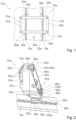
- an aircraft seat fastening device 10a is shown in a first exemplary embodiment.
- the aircraft seat fastening device 10a is intended to support an aircraft seat (not shown in detail) on a cabin floor 12a of an aircraft.
- the aircraft seat is designed as a business class seat or first class seat.
- the aircraft seat could in principle also be designed as an economy class seat or premium economy class seat.
- the aircraft seat and the aircraft seat fastening device 10a are included in an aircraft seat device.
- the aircraft seat device can have at least one housing, at least one console and/or at least one ottoman, which are coupled to the cabin floor 12a via the aircraft seat fastening device 10a.
- the aircraft seat device is intended to be fully assembled, in particular pre-assembled, and to be supported in an aircraft cabin of the aircraft.
- the aircraft seat is coupled to the cabin floor 12a via the aircraft seat fastening device 10a.
- the aircraft seat fastening device 10a is provided for fastening at least part of the aircraft seat to a fastening rail 14a fastened to an aircraft structure.
- the aircraft structure is designed as the cabin floor 12a of the aircraft cabin.
- the fastening rail 14a is firmly connected to the aircraft structure in an assembled state.
- the fastening rail 14a is firmly connected to the cabin floor 12a in an assembled state, in particular embedded in the cabin floor 12a.
- the fastening rail 14a is designed as an airline rail.
- the aircraft seat fastening device 10a is provided for fastening at least part of the aircraft seat to a further fastening rail 16a fastened to the aircraft structure.
- the further fastening rail 16a is designed identically to the fastening rail 14a.
- a main extension axis of the further fastening rail 16a is aligned parallel to a main extension axis of the fastening rail 14a.
- the aircraft seat fastening device 10a is provided for fastening at least part of the aircraft seat to the fastening rail 14a and the further fastening rail 16a.
- the aircraft seat fastening device 10a has a seat base structure 18a.
- the aircraft seat is intended for at least partial mounting on the seat base structure 18a.
- the aircraft seat is connected to the seat base structure 18a.
- the aircraft seat is not in direct contact with the cabin floor 12a.
- the at least one housing, the at least one console and/or the at least one ottoman are connected to the seat base structure 18a.
- the seat base structure 18a is spaced from the cabin floor 12a.
- the seat base structure 18a is not in direct contact with the cabin floor 12a.
- the seat base structure 18a is not in direct contact with the fastening rail 14a.
- the seat base structure 18a forms a platform on which at least the aircraft seat is arranged.
- the seat base structure 18a is designed as a frame in the present case.
- the seat base structure 18a has a plurality of interconnected support elements 20a, 22a, 24a, 26a which form the frame.
- the support elements 20a, 22a, 24a, 26a are
- the aircraft seat fastening device 10a has a seat foot unit 28a.
- the seat foot unit 28a comprises a connection base body 30a.
- the seat foot unit 28a comprises a compensation base body 32a.
- the seat foot unit 28a is provided to couple the seat base structure 18a to the fastening rail 14a.
- the seat foot unit 28a is arranged at a front end of the aircraft seat fastening device 10a.
- the seat direction 34a corresponds to a flight direction.
- the aircraft seat fastening device 10a has a further seat foot unit 36a.
- the further seat foot unit 36a is provided to couple the seat base structure 18a to the fastening rail 14a.
- the further Seat foot unit 36a is arranged at a rear end of the aircraft seat fastening device 10a.
- the further seat foot unit 36a has a pivot bearing (not shown in detail) which forms a pivot axis 38a which is aligned at least substantially parallel to the cabin floor 12a.
- the seat base structure 18a is pivotally mounted to the cabin floor 12a by means of the further seat foot unit 36a. Apart from a pivoting movement about the pivot axis 38a and a lateral movement in a transverse direction to the main extension axis of the fastening rail 14a, the further seat foot unit 36a does not allow any movement of the seat base structure 18a.
- the seat base structure 18a is at least partially moved away from the cabin floor 12a during a compensating movement.
- the seat base structure 18a is moved away from the cabin floor 12a on the seat foot unit 28a during the compensating movement.
- the seat base structure 18a is pivoted relative to the cabin floor 12a via the pivot axis 38a during the compensating movement.
- the compensating movement is intended to reduce and/or eliminate tensile, compressive and/or torsional loads on the aircraft seat fastening device 10a and/or on the aircraft seat that occur due to an overload, wherein the tensile and/or compressive forces can arise in particular due to a deformation of the cabin floor 12a.
- the overload case is designed as a crash case.
- the aircraft seat fastening device 10a has a second seat foot unit 40a.
- the second seat foot unit 40a comprises a second connection base body and a second compensation base body.
- the second seat foot unit 40a is designed identically to the seat foot unit 28a.
- the second seat foot unit 40a is provided to couple the seat base structure 18a to the further fastening rail 16a.
- the second seat foot unit 40a is arranged at the front end of the aircraft seat fastening device 10a.
- the aircraft seat fastening device 10a has a second additional seat foot unit 42a.
- the second additional seat foot unit 42a is designed identically to the additional seat foot unit 36a.
- the second additional seat foot unit 42a is provided to couple the seat base structure 18a to the additional fastening rail 16a.
- the second additional seat foot unit 42a is arranged at the rear end of the aircraft seat fastening device 10a.
- the second additional seat foot unit 42a has a pivot bearing (not shown in detail) which has a pivot axis 44a. which is aligned at least substantially parallel to the cabin floor 12a.
- the seat base structure 18a is pivotally mounted to the cabin floor 12a by means of the second additional seat foot unit 42a.
- the second additional seat foot unit 42a does not allow any movement of the seat base structure 18a.
- the seat foot unit 28a is provided to allow at least one compensating movement of the seat base structure 18a, in particular relative to the fastening rail 14a.
- the seat foot unit 28a is provided to allow the at least one compensating movement between the seat base structure 18a and the cabin floor 12a without causing any damage.
- the compensating movement permitted by the seat foot unit 28a is limited.
- the at least one compensating movement is designed as a linear movement.
- the seat foot unit 28a is shown in a normal position in which the compensation base body 32a is in a normal operating state relative to the connection base body 30a.
- the seat foot unit 28a is shown in a compensating position in which the compensating base body 32a is maximally displaced from the normal position, in particular by the at least one compensating movement, relative to the connecting base body 30a.
- the aircraft seat fastening device 10a is shown in a position in which the aircraft seat fastening device 10a is positioned for coupling with the fastening rail 14a, but is not yet inserted into it.
- the aircraft seat fastening device 10a has a fitting element 46a.
- the fitting element 46a is intended to be coupled with the fastening rail 14a. In a fully assembled state, the fitting element 46a is held in a recess in the cabin floor 12a, in particular in the fastening rail 14a.
- the fastening rail 14a forms a hollow profile which is intended for a positive connection with the fitting element 46a.
- the fastening rail 14a has a guide opening 48a on its upper side through which at least a part of the fitting element 46a is guided in an assembled state.
- the fastening rail 14a has, at at least substantially equal intervals, mounting regions 50a in which the guide opening 48a has a wider cross-section.
- the guide opening 48a is substantially circular in the mounting regions 50a.
- the mounting regions 50a are provided for introducing a holding section 52a of the fitting element 46a through one of the mounting regions 50a into the fastening rail 14a in order to produce a positive connection with the fastening rail 14a.
- the fitting element 46a can be pivoted within a limited angular range about an axis that is aligned parallel to a support plane and is arranged in particular at the level of the guide opening 48a. This makes it possible to achieve an advantageously stress-free pivoting of the seat base structure 18a during a compensating movement.
- the limited angular range extends from a normal on the support plane by preferably at most 20 degrees and particularly preferably by at most 10 degrees.
- the support plane is formed by the cabin floor 12a.
- connection base body 30a is connected to the fitting element 46a.
- the fitting element 46a is connected to the connection base body 30a in a force-fitting and/or form-fitting manner.
- the fitting element 46a is firmly, in particular rigidly, connected to the connection base body 30a.
- the connection base body 30a is intended to connect the seat foot unit 28a to the fastening rail 14a via the fitting element 46a.
- the compensation base body 32a is rigidly connected to the seat base structure 18a in every operating state.
- the compensation base body 32a is intended to connect the seat foot unit 28a to the seat base structure 18a.
- the compensation base body 32a is connected to the seat base structure 18a in a force-fitting and form-fitting manner.
- the aircraft seat fastening device 10a has a fastening plate 54a.
- the fastening plate 54a is arranged on a side of a support element 20a of the seat base structure 18a facing away from the compensation base body 32a.
- the fastening plate 54a is intended to press the compensation base body 32a onto the support element 20a over a large part of the height of the support element 20a of the seat base structure 18a.
- the aircraft seat fastening device 10a has several screws.
- Fastening means 56a which are intended to firmly connect the compensation base body 32a to the seat base structure 18a.
- the carrier element 20a of the seat base structure 18a is arranged in a form-fitting manner between the fastening plate 54a and the compensation base body 32a in an assembled state.
- the compensation base body 32a is intended to carry out the at least one compensation movement relative to the fastening rail 14a in the event of an overload.
- the compensation base body 32a is intended to carry out the at least one compensation movement relative to the cabin floor 12a in the event of an overload.
- the compensation base body 32a is mounted so that it can be moved in translation relative to the connection base body 30a.
- the connection base body 30a and the compensation base body 32a are coupled to one another via two rail connections 58a, 60a.
- the two rail connections 58a, 60a are spatially separated from one another.
- the seat foot unit 28a has the two rail connections 58a, 60a.
- the connection base body 30a and the compensation base body 32a are mounted so that they can move relative to one another, in particular slide against one another, via the two rail connections 58a, 60a along a guide track 62a.
- the compensation base body 32a and the connection base body 30a are mounted so that they slide against one another.
- connection base body 30a and the compensation base body 32a are each formed at least substantially from a metallic material, in particular steel.
- the connection base body 30a and the compensation base body 32a are each surface-treated, in particular chromated, in particular at least in one area of the rail connections 58a, 60a. This advantageously prevents the connection base body 30a and the compensation base body 32a from sticking to one another, in particular due to corrosion, and thus increases operational reliability.
- the connection base body 30a has two elongated grooves 64a.
- the compensation base body 32a has two elongated extensions 66a.
- One of the grooves 64a and one of the extensions 66a form a pair of rail connections 58a, 60a.
- Each of the rail connections 58a, 60a has one of the grooves 64a and one of the extensions 66a.
- the extension 66a is designed to correspond to the groove 64a.
- the extension 66a engages in the groove 64a.
- the extension 66a is slidably mounted in the groove 64a.
- the extension 66a is arranged at least partially in the groove 64a in a coupled state of the connection base body 30a and the compensation base body 32a, in particular in the normal position and in the compensation position of the seat foot unit 28a.
- the rail connections 58a, 60a are mirrored to one another via a plane of symmetry of the seat foot unit 28a, which is aligned at least substantially perpendicular to the support plane.
- the two rail connections 58a, 60a are arranged in such a way that they positively couple the connection base body 30a and the compensation base body 32a in two translational degrees of freedom.
- the extensions 66a of the rail connections 58a, 60a are each arranged on opposite inner sides of the compensation base body 32a.
- the grooves 64a of the rail connections 58a, 60a are each arranged on mutually opposite outer sides of the connection base body 30a.
- the compensation base body 32a it would also be conceivable for the compensation base body 32a to have the two grooves 64a and the connection base body 30a to have the two extensions 66a.
- the groove 64a has an at least substantially rectangular cross-section.
- the extension 66a has an at least substantially rectangular cross-section.
- the groove 64a and the extension 66a can also have another shape that appears suitable to the person skilled in the art, whereby a groove and an extension must have a shape that corresponds to one another.
- the groove and the extension are positively coupled to one another via an undercut of the groove and/or the extension, viewed in a cross-sectional plane, in particular in two translational degrees of freedom.
- the groove could have a T-shaped cross-section, whereby the extension has a T-shaped cross-section and is arranged in the groove.
- only one rail connection is provided for coupling the compensation base body 32a to the connection base body 30a, in particular with a positive coupling of the groove and the extension in a cross-sectional plane.
- the guide track 62a describes a straight line. In principle, however, it would be conceivable for the guide track 62a to describe a circular arc section.
- the guide track 62a is arranged in a plane. The plane in which the guide track 62a is arranged is aligned perpendicular to the cabin floor 12a.
- the plane in which the guide track 62a is arranged is aligned parallel to the main extension axis of the fastening rail 14a.
- Main extension paths of the rail connections 58a, 60a are each aligned at least substantially perpendicular to the support plane.
- the main extension paths of the rail connections 58a, 60a are designed as main extension axes.
- the main extension paths of the rail connections 58a, 60a each run on an end face of the extension 66a of the rail connections 58a, 60a.
- the main extension paths of the rail connections 58a, 60a each run parallel to a main extension axis of the groove 64a of the rail connections 58a, 60a.
- the main extension paths of the rail connections 58a, 60a each run parallel to a main extension axis of the extension 66a of the rail connections 58a, 60a.
- the main extension paths of the rail connections 58a, 60a are arranged in planes parallel to one another, whereby the main extension paths are congruent when viewed perpendicular to the planes.
- the main extension paths of the rail connections 58a, 60a and the guide path 62a are congruent in a projection plane (cf. Figure 4 ).
- connection base body 30a and a lateral surface of the compensation base body 32a form a flush surface, at least in the normal position.
- the seat foot unit 28a has a locking unit 68a.
- the locking unit 68a is provided to block and/or limit a movement of the seat base structure 18a in at least one direction. The at least one direction is aligned at least substantially perpendicular to the support plane.
- the locking unit 68a is provided to block and/or limit the at least one compensating movement of the seat base structure 18a in at least one direction.
- the locking unit 68a is provided to limit a compensating movement of the seat base structure 18a in a direction that is directed away from the support plane, in particular from the cabin floor 12a.
- the locking unit 68a is provided to block a compensating movement of the seat base structure 18a in a direction that is directed towards the support plane, in particular towards the cabin floor 12a.
- the locking unit 68a comprises a form-locking element 70a.
- the form-locking element 70a is designed as a leaf spring. In the present case, the leaf spring is made of spring steel.
- the form-locking element 70a is intended to engage in a corresponding locking structure 72a of the connection base body 30a.
- the locking structure 72a of the connection base body 30a is part of the locking unit 68a.
- the form-locking element 70a is plate-shaped.
- the form-locking element 70a has a locking region 74a which is intended to contact the corresponding locking structure 72a of the connection base body 30a.
- the form-locking element 70a is angled in the locking region 74a, in particular with respect to a large part of the form-locking element 70a.
- a main extension axis of the form-locking element 70a is aligned at least substantially perpendicular to the support plane.
- the locking structure 72a of the connection base body 30a has several identically designed, wedge-shaped extensions 76a.
- the extensions 76a of the locking structure 72a are arranged along an axis that is aligned at least substantially perpendicular to the support plane.
- the locking structure 72a of the connection base body 30a is intended to allow the form-locking element 70a to slide past in a direction away from the support plane.
- the locking structure 72a of the connection base body 30a is intended to block a movement of the form-locking element 70a in a direction toward the support plane.
- the form-locking element 70a has a groove 78a.
- a main extension path of the groove 78a of the form-locking element 70a is aligned at least substantially parallel to the main extension paths of the rail connections 58a, 60a.
- the groove 78a of the form-locking element 70a is designed as an elongated hole.
- the groove 78a of the form-locking element 70a is designed as a through hole in the present case.
- the groove 78a of the form-locking element 70a does not extend into the angled locking area 74a of the form-locking element 70a.
- the locking unit 68a comprises a stop element 80a.
- the stop element 80a is firmly connected to the connection base body 30a.
- the stop element 80a is guided in the groove 78a of the form-locking element 70a.
- the stop element 80a is provided to limit a displacement of the seat base structure 18a, in particular a displacement of the compensation base body 32a to the connection base body 30a.
- the groove 78a of the form-locking element 70a is provided to to limit the maximum displacement of the compensation base body 32a to the connection base body 30a.
- the stop element 80a is guided in the groove 78a of the form-locking element 70a.
- the stop element 80a protrudes into the groove 78a of the form-locking element 70a.
- the stop element 80a is cylindrical.
- the stop element 80a is integrally connected to the connection base body 30a.
- the stop element 80a is designed as an extension of the connection base body 30a (cf. Figures 3 and 4 ).
- the extension can be produced, for example, by milling on the connection base body 30a.
- a stop element 80'a of the locking unit 68a can be screwed into the connection base body 30a.
- This alternative design of the stop element 80'a is shown in the Figure 5 shown.
- the stop element 80'a is in this case designed as a bolt or as a screw.
- the form-locking element 70a comprises two deformation elements 79a.
- the form-locking element 70a is designed to be plastically deformed at least in some areas during a compensating movement.
- the deformation elements 79a are designed to deform in order to allow the stop element 80a, 80'a to move through the groove 78a.
- the deformation elements 79a are each designed as an elevation that rises towards one another from opposite inner sides of the groove 78a.
- the deformation elements 79a narrow the groove 78a in an area in which the deformation elements 79a are arranged.
- the stop element 80a, 80'a is pressed against the deformation elements 79a, wherein the deformation elements 79a are plastically deformed from a defined force that is in particular greater than a defined handhold load.
- the deformation elements 79a are elastically deflected when the defined force is reached and in particular are not plastically deformed.
- the defined force is reached in the event of an overload.
- the defined force is greater than a handhold load at which supporting forces from a person act on the aircraft seat device, on the aircraft seat and/or on the seat base structure 18a.
- the stop element 80a, 80'a In the normal position of the seat foot unit 28a, the stop element 80a, 80'a is fixed in the groove 78a by means of the deformation elements 79a. From the defined force, the Deformation elements 79a and/or are pressed out of the groove 78a. By deforming the deformation elements 79a, the stop element 80a, 80'a can be moved within the entire groove 78a, thereby enabling a compensating movement of the compensating base body 32a to the connecting base body 30a.
- the form-fitting element 70a is connected to the compensation base body 32a in a form-fitting and force-fitting manner by means of a fastening element 82a of the locking unit 68a.
- a main extension axis of the fastening element 82a is aligned at least substantially parallel to the support plane.
- the fastening element 82a is designed as a screw.
- the fastening element 82a has a cylinder head 84a.
- the cylinder head 84a is arranged on the outside of the compensation base body 32a.
- connection base body 30a has a recess 86a.
- the recess 86a of the connection base body 30a is intended to partially accommodate the fastening element 82a of the locking unit 68a.
- the connection base body 30a has a stop area 88a.
- the stop area 88a is arranged in the recess 86a of the connection base body 30a.
- the recess 86a is rounded in the stop area 88a, in particular semicircular.
- the fastening element 82a is partially arranged in the stop area 88a in the normal position of the seat foot unit 28a.
- the fastening element 82a is intended to be moved out of the recess 86a in the event of an overload.
- the fastening element 82a in particular the cylinder head 84a of the fastening element 82a, is intended to abut against the connection base body 30a in the stop region 88a.
- the stop region 88a is intended to limit a movement of the compensation base body 32a in a direction towards the support plane.
- the aircraft seat fastening device 10a has a fitting locking element 90a.
- the fitting locking element 90a is designed as a latch.
- the fitting locking element 90a is provided to lock the fitting element 46a in the fastening rail 14a.
- the fitting locking element 90a is provided to block the fitting element 46a, in particular the holding section 52a of the fitting element 46a, along the main extension axis of the fastening rail 14a.
- the fitting locking element 90a is in a retracted position of the Fitting locking element 90a is arranged in the guide opening 48a of the fastening rail 14a.
- the fitting locking element 90a is arranged in the countersunk position in one of the mounting areas 50a of the fastening rail 14a.
- the fitting locking element 90a forms a positive connection along the main extension axis of the fastening rail 14a in the position countersunk in the fastening rail 14a.
- the fitting locking element 90a forms a receiving area 92a on a side of the fitting locking element 90a facing the fitting element 46a, which is formed in the holding section 52a in a manner corresponding to a shape of the fitting element 46a.
- the fitting locking element 90a can be partially retracted into the fastening rail 14a.
- the fitting locking element 90a is intended to be inserted into the fastening rail 14a, in particular into the hollow profile formed by the fastening rail 14a, when the fitting element 46a is locked to the fastening rail 14a.
- the fitting locking element 90a is mounted on the connection base body 30a so that it can move in translation.
- the fitting locking element 90a is mounted on the connection base body 30a so that it can move in translation along a movement axis of the fitting locking element 90a.
- the movement axis of the fitting locking element 90a is aligned at least substantially perpendicular to the main extension axis of the fastening rail 14a.
- the fitting locking element 90a and the connection base body 30a are coupled to one another via two further rail connections 94a, 96a.
- the fitting locking element 90a is designed to be retractable by means of the two additional rail connections 94a, 96a.
- the fitting locking element 90a is slidably mounted on the connection base body 30a.
- the fitting locking element 90a is movably mounted via the additional rail connections 94a, 96a along the movement axis of the fitting locking element 90a.
- the fitting locking element 90a has two extensions 98a in an upper region of the fitting locking element 90a, which extend away from the fitting locking element 90a on opposite sides of the fitting locking element 90a.
- the extensions 98a of the fitting locking element 90a are provided to prevent movement of the Fitting locking element 90a in the direction of the support plane. In the sunk position, the extensions 98a each rest on projections 100a of the connection base body 30a.
- the extensions 98a are formed by a pin element that is connected to the fitting locking element 90a.
- the extensions 98a of the fitting locking element 90a have a common main extension axis.
- the main extension axis of the extensions 98a of the fitting locking element 90a is aligned at least substantially parallel to the support plane.
- the main extension axis of the extensions 98a of the fitting locking element 90a is aligned at least substantially perpendicular to the main extension axis of the fastening rail 14a.
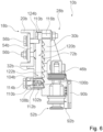
- an aircraft seat fastening device 10b is shown in a second embodiment.
- the Figure 1 is basically also valid for the second embodiment.
- the aircraft seat fastening device 10b is intended to support an aircraft seat (not shown in detail) on a cabin floor of an aircraft.
- the aircraft seat fastening device 10b is intended to fasten at least part of the aircraft seat to a fastening rail fastened to an aircraft structure.
- the aircraft seat fastening device 10b has a seat base structure 18b.
- the seat base structure 18b has several interconnected support elements 20b.
- the aircraft seat fastening device 10b has a seat foot unit 28b.
- the seat foot unit 28b comprises a connection base body 30b.
- the seat foot unit 28b comprises a compensation base body 32b.
- the seat foot unit 28b is shown in a normal position in which the compensation base body 32b is in a Normal operating state relative to the connection body 30b.
- the seat foot unit 28b is shown in a compensation position in which the compensation base body 32b is maximally displaced from the normal position, in particular by the at least one compensation movement, relative to the connection base body 30b.
- the aircraft seat fastening device 10b has a fitting element 46b.
- the aircraft seat fastening device 10b has a fastening plate 54b.
- the aircraft seat fastening device 10b has several fastening means 56b designed as screws or bolts, which are intended to firmly connect the compensation base body 32b to the seat base structure 18b.
- connection base body 30b and the compensation base body 32b are coupled to one another in the present case via two rail connections 58b, wherein in the Figures 6 and 7 only one of the two rail connections 58b is visible.
- the connection base body 30b and the compensation base body 32b are mounted so as to be movable relative to one another, in particular sliding relative to one another, via the two rail connections 58b along a guide track 62b.
- Each of the rail connections 58b has a Figures 6 and 7 not visible groove, which is arranged in the connection base body 30b.
- Each of the rail connections 58b has an extension 66b, which is arranged on the compensation base body 32b.
- the aircraft seat fastening device 10b has a fitting locking element 90b.
- the fitting locking element 90b and the connection base body 30b are coupled to one another via two further rail connections, not shown in detail.
- the fitting locking element 90b forms a receiving area 92b on a side of the fitting locking element 90b facing the fitting element 46b, which is formed in the holding area 52b to correspond to a shape of the fitting element 46b.
- a design of the fitting locking element 90b and a connection of the fitting locking element 90b to the connection base body 30b corresponds to the design from the first exemplary embodiment.
- the seat foot unit 28b has a locking unit 102b.
- the locking unit 102b from the second embodiment is designed differently.
- the locking unit 102b is intended to block and/or limit a movement of the seat base structure 18b in at least one direction.
- the locking unit 102b comprises a form-locking element 104b.
- the form-locking element 104b is intended to engage in a corresponding locking structure 72b of the connection base body 30b.
- the form-locking element 104b is mounted so as to be translationally movable relative to the compensation base body 32b.
- the form-locking element 104b has a locking structure 106b.
- the form-locking element 104b has two wedge-shaped extensions which form the locking structure 106b of the form-locking element 104b and which are designed to correspond to the locking structure 72b of the connection base body 30b.
- the form-locking element 104b is mounted at least partially in the compensation base body 32b.
- a movement axis of the form-locking element 104b is aligned at least substantially parallel to the support plane.
- the movement axis of the form-locking element 104b is aligned at least substantially perpendicular to the guide track 62b of the rail connections 58b.
- the compensation base body 32b has a recess 108b in which the form-locking element 104b is mounted.
- the form-locking element 104b is slidably mounted in the recess 108b of the compensation base body 32b.
- the form-locking element 104b is provided to be deflected during the compensation movement along the movement axis of the form-locking element 104b, in particular into the recess 108b of the compensation base body 32b.
- the locking unit 102b has a spring element 110b.
- the spring element 110b is arranged between the compensation base body 32b and the form-locking element 104b and is intended to press the form-locking element 104b against the corresponding locking structure 72b of the connection base body 30b.
- the spring element 110b is designed as a compression spring.
- the spring element 110b is arranged in the recess 108b of the compensation base body 32b.
- an effective axis of the spring element 110b is aligned parallel to the movement axis of the form-locking element 104b.
- the form-locking element 104b has a cavity 112b in which the spring element 110b is arranged.
- the locking unit 102b has an adjusting means 114b, which is provided to pre-tension the spring element 110b, in particular against the form-locking element 104b.
- the adjusting means 114b is designed as a screw or as a bolt.
- the adjusting means 114b is partially arranged in the recess 108b.
- the adjusting means 114b is screwed into the compensation base body 32b from a side of the compensation base body 32b facing away from the recess 108b.
- the locking unit 102b comprises a stop element 116b.
- the stop element 116b is firmly connected to the connection base body 30b.
- the stop element 116b is connected to the connection base body 30b in a force-fitting and form-fitting manner.
- the stop element 116b is designed as a screw or as a bolt.
- the stop element 116b has a cylinder head 118b.
- the cylinder head 118b is arranged on the outside of the connection base body 30b.
- the cylinder head 118b faces the compensation base body 32b.
- the compensation base body 32b has a groove 120b.
- the stop element 116b is guided in the groove 120b of the compensation base body 32b.
- the stop element 116b is provided to limit a displacement of the seat base structure 18b, in particular a displacement of the compensation base body 32b to the connection base body 30b.
- the groove 120b of the compensation base body 32b is provided to limit a maximum displacement of the compensation base body 32b to the connection base body 30b.
- the stop element 116b is guided in the groove 120b of the compensation base body 32b.
- the stop element 116b protrudes into the groove 120b of the compensation base body 32b.
- the stop element 116b is cylindrical.
- a main extension axis of the stop element 116b is aligned at least substantially parallel to the support plane.
- the compensation base body 32b has an upper stop area 124b.
- the upper stop area 124b is arranged in the groove 120b of the compensation base body 32b.
- the groove 120b is rounded in the upper stop area 124b, in particular semicircular.
- the stop element 116b is arranged in the upper stop area 124b in the normal position of the seat foot unit 28b.
- the compensation base body 32b has a lower stop area 122b.
- the lower stop area 122b is arranged in the groove 120b of the compensation base body 32b.
- the groove 120b is rounded in the lower stop area 122b, in particular semicircular.
- the stop element 116b is arranged in the lower stop area 122b in the compensation position of the seat foot unit 28b.
- the stop element 116b in particular the cylinder head 118b of the In the event of an overload, the stop element 116b is intended to strike against the compensation base body 32b in the lower stop region 122b.
Landscapes
- Engineering & Computer Science (AREA)
- Aviation & Aerospace Engineering (AREA)
- Seats For Vehicles (AREA)
Description
- Die Erfindung betrifft eine Flugzeugsitzbefestigungsvorrichtung nach dem Oberbegriff des Patentanspruchs 1.
- Aus der Druckschrift
WO 2020/035571 A1 ist bereits eine Flugzeugsitzbefestigungsvorrichtung zur Befestigung wenigstens eines Teils eines Flugzeugsitzes an zumindest einer, an einer Flugzeugstruktur befestigten Befestigungsschiene, mit einer Sitzgrundstruktur, mit zumindest einem Fittingelement, das dazu vorgesehen ist, mit der Befestigungsschiene gekoppelt zu werden, und mit wenigstens einer Sitzfußeinheit, die zumindest in einem Überlastfall dazu vorgesehen ist, zumindest eine Ausgleichsbewegung der Sitzgrundstruktur, insbesondere relativ zu der Befestigungsschiene, zuzulassen, vorgeschlagen worden. - Die Aufgabe der Erfindung besteht insbesondere darin, eine gattungsgemäße Vorrichtung mit verbesserten Eigenschaften hinsichtlich einer Sicherheit, insbesondere durch eine Reduzierung von Lasten in einer Befestigungsschiene bereitzustellen. Die Aufgabe wird erfindungsgemäß durch die Merkmale des Patentanspruchs 1 gelöst, während vorteilhafte Ausgestaltungen und Weiterbildungen der Erfindung den Unteransprüchen entnommen werden können.
- Die Erfindung geht aus von einer Flugzeugsitzbefestigungsvorrichtung zur Befestigung wenigstens eines Teils eines Flugzeugsitzes an zumindest einer, an einer Flugzeugstruktur befestigten Befestigungsschiene, mit einer Sitzgrundstruktur, mit zumindest einem Fittingelement, das dazu vorgesehen ist, mit der Befestigungsschiene gekoppelt zu werden, und mit wenigstens einer Sitzfußeinheit, die zumindest in einem Überlastfall dazu vorgesehen ist, zumindest eine Ausgleichsbewegung der Sitzgrundstruktur, insbesondere relativ zu der Befestigungsschiene, zuzulassen.
- Es wird vorgeschlagen, dass die wenigstens eine Sitzfußeinheit einen Anbindungsgrundkörper, welcher mit dem Fittingelement verbunden ist, und einen Ausgleichsgrundkörper, welcher in jedem Betriebszustand starr mit der Sitzgrundstruktur verbunden ist, aufweist, wobei der Anbindungsgrundkörper und der Ausgleichsgrundkörper über zumindest eine Schienenverbindung miteinander gekoppelt und entlang einer Führungsbahn beweglich zueinander gelagert sind. Durch eine erfindungsgemäße Ausgestaltung kann eine vorteilhaft sichere Flugzeugsitzbefestigungsvorrichtung bereitgestellt werden. Durch die erfindungsgemäße Ausgestaltung kann eine Ausgleichsbewegung vorteilhaft definiert entlang der Führungsbahn erfolgen. Dadurch kann eine Schädigung und/oder ein Versagen der Sitzgrundstruktur und/oder des Flugzeugsitzes in dem Überlastfall vorteilhaft vermieden werden. Ferner kann durch die erfindungsgemäße Ausgestaltung eine vorteilhaft stabile Kopplung des Anbindungsgrundkörpers und des Ausgleichsgrundkörpers erreicht werden. Zudem kann durch die erfindungsgemäße Ausgestaltung eine vorteilhaft kompakte Sitzfußeinheit bereitgestellt werden.
- Unter einer "Flugzeugsitzbefestigungsvorrichtung" soll vorzugsweise eine Vorrichtung verstanden werden, die dazu vorgesehen ist, den Flugzeugsitz und/oder eine Flugzeugsitzanordnung auf einer Aufständerebene zumindest teilweise zu befestigen. Vorzugsweise ist die Flugzeugsitzbefestigungsvorrichtung dazu vorgesehen, den Flugzeugsitz auf einem Kabinenboden eines Flugzeugs aufzuständern. Unter "vorgesehen" soll insbesondere speziell ausgelegt und/oder ausgestattet verstanden werden. Darunter, dass ein Objekt zu einer bestimmten Funktion vorgesehen ist, soll insbesondere verstanden werden, dass das Objekt diese bestimmte Funktion in zumindest einem Anwendungs- und/oder Betriebszustand erfüllt und/oder ausführt. Unter einem "Flugzeugsitz" soll vorzugsweise ein Sitz verstanden werden, der dazu vorgesehen ist, in einer Flugzeugkabine eines Flugzeugs aufgeständert zu werden, wobei ein Passagier während eines Fluges auf dem Flugzeugsitz sitzen kann. Vorzugsweise ist der Flugzeugsitz zu einer Montage auf der Sitzgrundstruktur vorgesehen. Besonders bevorzugt ist der Flugzeugsitz mit der Sitzgrundstruktur verbunden. Vorzugsweise steht der Flugzeugsitz nicht in direktem Kontakt mit dem Kabinenboden. Vorzugsweise ist der Flugzeugsitz als ein Business-Class oder First-Class-Sitz ausgebildet. Grundsätzlich kann die Flugzeugsitzbefestigungsvorrichtung auch zur Befestigung wenigstens eines Teils zumindest einer Umhausung, zumindest einer Konsole und/oder zumindest einer Ottomane an der Flugzeugstruktur vorgesehen sein. Vorzugsweise ist die zumindest eine Umhausung, die zumindest eine Konsole und/oder die zumindest eine Ottomane mit der Sitzgrundstruktur verbunden.
- Unter einer "Sitzgrundstruktur" soll insbesondere eine tragende Struktur verstanden werden, über die Gewichtskräfte des Flugzeugsitzes und/oder Gewichtskräfte von weiteren Teilen, insbesondere der zumindest einen Umhausung, der zumindest einen Konsole und/oder der zumindest einen Ottomane, sowie gegebenenfalls Gewichtskräfte eines auf dem Flugzeugsitz sitzenden Passagiers, insbesondere über die wenigstens eine Sitzfußeinheit, in die Flugzeugstruktur eingeleitet werden können. Vorzugsweise ist die Sitzgrundstruktur als ein Rahmen ausgebildet. Vorzugsweise weist die Sitzgrundstruktur mehrere miteinander verbundene Trägerelemente auf, die insbesondere den Rahmen ausbilden. Alternativ kann die Sitzgrundstruktur auch als eine Aufnahmeplatte ausgebildet sein. Vorzugsweise bildet die Sitzgrundstruktur eine Plattform aus, auf der der Flugzeugsitz angeordnet werden kann. Grundsätzlich ist es ebenfalls denkbar, dass die Sitzgrundstruktur als ein Teil einer Aufständereinheit ausgebildet ist. Vorzugsweise ist die Sitzgrundstruktur von dem Kabinenboden beabstandet. Vorzugsweise steht die Sitzrundstruktur nicht in direktem Kontakt mit dem Kabinenboden.
- Unter einer "Flugzeugstruktur" soll vorzugsweise eine Tragstruktur des Flugzeugs verstanden werden, mit der der Flugzeugsitz zu einer betriebssicheren Verwendung in der Flugzeugkabine fest gekoppelt werden kann. Vorzugsweise ist die Flugzeugstruktur zumindest teilweise als der Kabinenboden der Flugzeugkabine ausgebildet.
- Unter einem "Fittingelement" soll vorzugsweise ein Element verstanden werden, das zu einer Befestigung eines mit dem Fittingelement verbundenen Bauteils, insbesondere der Sitzfußeinheit und/oder der Sitzgrundstruktur, an dem Kabinenboden vorgesehen ist. Vorzugsweise ist das Fittingelement in einem vollständig montierten Zustand in einer Ausnehmung in dem Kabinenboden, insbesondere in der Befestigungsschiene, gehalten.
- Vorzugsweise ist die zumindest eine Befestigungsschiene in einem montierten Zustand fest mit der Flugzeugstruktur verbunden. Vorzugsweise ist die zumindest eine Befestigungsschiene in einem montierten Zustand fest mit dem Kabinenboden verbunden, insbesondere in den Kabinenboden eingelassen. Vorzugsweise bildet die zumindest eine Befestigungsschiene ein Hohlprofil aus, das zu einer formschlüssigen Verbindung mit einem Element, insbesondere des Fittingelements, vorgesehen ist. Vorzugsweise weist die zumindest eine Befestigungsschiene auf ihrer Oberseite eine Führungsöffnung auf, durch die in einem montierten Zustand zumindest ein Teil des Fittingelements geführt ist. Vorzugsweise weist die zumindest eine Befestigungsschiene in zumindest im Wesentlichen gleichen Abständen Montagebereiche auf, in denen die Führungsöffnung jeweils einen breiteren Querschnitt aufweist. Unter "zumindest im Wesentlichen" soll vorzugsweise verstanden werden, dass eine Abweichung von einem vorgegebenen Wert insbesondere weniger als 25 %, vorzugsweise weniger als 10 % und besonders bevorzugt weniger als 5 % des vorgegebenen Werts beträgt. Vorzugsweise ist die Führungsöffnung in den Montagebereichen im Wesentlichen kreisrund ausgebildet. Bevorzugt sind die Montagebereiche zu einer Einführung eines Halteabschnitts des Fittingelements durch einen der Montagebereiche in die Befestigungsschiene zur Herstellung einer formschlüssigen Verbindung mit der Befestigungsschiene vorgesehen.
- Unter einer "Sitzfußeinheit" soll vorzugsweise eine Einheit verstanden werden, die dazu vorgesehen ist, die Sitzgrundstruktur auf dem Kabinenboden aufzuständern, insbesondere die Sitzgrundstruktur mit der zumindest einen Befestigungsschiene zu koppeln. Vorzugsweise ist die wenigstens eine Sitzfußeinheit dazu vorgesehen, eine Ausgleichsbewegung zwischen der Sitzgrundstruktur und dem Kabinenboden zumindest im Wesentlichen zerstörungsfrei zuzulassen. Bevorzugt ist die von der wenigstens einen Sitzfußeinheit zugelassene Ausgleichsbewegung begrenzt. Vorzugsweise ist die Ausgleichsbewegung als eine Rotationsbewegung, als eine Linearbewegung oder als eine Kombination einer Rotations- und einer Linearbewegung ausgebildet. Unter "zerstörungsfrei" soll vorzugsweise verstanden werden, dass durch die Ausgleichsbewegung keine Elemente der Flugzeugsitzbefestigungsvorrichtung mechanisch beschädigt, insbesondere plastisch verformt, werden. Grundsätzlich ist es denkbar, dass ein Element der wenigstens einen Sitzfußeinheit bei einer Ausgleichsbewegung plastisch deformiert wird. Dabei ist es vorstellbar, dass dieses Element den Anbindungsgrundkörper und den Ausgleichsgrundkörper bei einer Belastung mit definierten Handholdlasten zueinander fixiert, wobei das Element bei einer Überschreitung der definierten Handholdlasten, insbesondere in dem Überlastfall, plastisch deformiert wird, um eine Ausgleichsbewegung aus einer Normalstellung zu ermöglichen.
- Vorzugsweise ist der Anbindungsgrundkörper dazu vorgesehen, die Sitzfußeinheit über das Fittingelement an die Befestigungsschiene anzubinden. Vorzugsweise ist das Fittingelement kraftschlüssig und/oder formschlüssig mit dem Anbindungsgrundkörper verbunden. Alternativ oder zusätzlich wäre es denkbar, dass das Fittingelement stoffschlüssig mit dem Anbindungsgrundkörper verbunden ist.
- Vorzugsweise ist der Ausgleichsgrundkörper dazu vorgesehen, die Sitzfußeinheit mit der Sitzgrundstruktur zu verbinden. Vorzugsweise ist der Ausgleichsgrundkörper kraftschlüssig und/oder formschlüssig mit der Sitzgrundstruktur verbunden. Unter "kraftschlüssig und/oder formschlüssig verbunden" soll vorzugsweise eine lösbare Verbindung verstanden werden, wobei eine Haltekraft zwischen zwei Bauteilen vorzugsweise durch einen geometrischen Eingriff der Bauteile ineinander und/oder eine Reibkraft zwischen den Bauteilen übertragen wird. Alternativ oder zusätzlich wäre es denkbar, dass der Ausgleichsgrundkörper stoffschlüssig mit der Sitzgrundstruktur verbunden ist. Unter "stoffschlüssig verbunden" soll vorzugsweise durch einen Schweißprozess und/oder Klebeprozess verbunden und besonders vorteilhaft angeformt verstanden werden, wie durch die Herstellung aus einem Guss und/oder durch die Herstellung in einem Ein- oder Mehrkomponentenspritzverfahren. Vorzugsweise ist der Ausgleichsgrundkörper dazu vorgesehen, in dem Überlastfall die zumindest eine Ausgleichsbewegung relativ zu der Befestigungsschiene auszuführen. Vorzugsweise ist der Ausgleichsgrundkörper dazu vorgesehen, in dem Überlastfall die zumindest eine Ausgleichsbewegung relativ zu dem Kabinenboden auszuführen.
- Unter einer "Ausgleichsbewegung" soll vorzugsweise eine Relativbewegung wenigstens zweier Elemente zueinander verstanden werden, die vorzugsweise zerstörungsfrei abläuft. Vorzugsweise wird eine Ausgleichsbewegung in dem Überlastfall ausgeführt, in dem zumindest eine Grenzlast für die Flugzeugsitzbefestigungsvorrichtung überschritten wird, und insbesondere nicht in einem Normalbetriebszustand. Vorzugsweise wird die Sitzgrundstruktur während einer Ausgleichsbewegung zumindest teilweise von dem Kabinenboden wegbewegt. Vorzugsweise wird die Sitzgrundstruktur bei der Ausgleichsbewegung gegenüber dem Kabinenboden verschwenkt. Vorzugsweise ist die Ausgleichsbewegung dazu vorgesehen, durch den Überlastfall auftretende Zug-, Druck- und/oder Torsionsbelastungen auf die Flugzeugsitzbefestigungsvorrichtung und/oder auf den Flugzeugsitz zu reduzieren und/oder zu eliminieren, wobei die Zug- und/oder Druckkräfte insbesondere durch eine Verformung des Kabinenbodens entstehen können. Unter einem "Überlastfall" soll vorzugsweise ein von einem Normalbetrieb verschiedener Betriebszustand verstanden werden, in dem insbesondere höhere Beschleunigungskräfte als in dem Normalbetrieb wirken. Bevorzugt ist der Überlastfall als ein Crashfall ausgebildet.
- Grundsätzlich ist es möglich, dass sich der Kabinenboden in dem Überlastfall verformt, insbesondere verwindet. Dabei ist es möglich, dass sich die zumindest eine Befestigungsschiene in dem Überlastfall verformt. Durch die erfindungsgemäße Ausgestaltung kann eine Verwindung der Sitzgrundstruktur in dem Überlastfall vorteilhaft vermieden werden. Dadurch kann ein Bruch der Sitzgrundstruktur und/oder der zumindest einen Befestigungsschiene mittels der Flugzeugsitzbefestigungsvorrichtung vorteilhaft vermieden werden. Vorzugsweise ist die Flugzeugsitzbefestigungsvorrichtung dazu vorgesehen, durch den Überlastfall auftretende Verformungen der zumindest einen Befestigungsschiene auszugleichen, damit die Sitzgrundstruktur auch in dem Überlastfall zumindest im Wesentlichen verwindungsfrei ist. Vorzugsweise wird die Flugzeugsitzbefestigungsvorrichtung, insbesondere die Flugzeugsitzvorrichtung, zur Prüfung von Verformungen der Sitzgrundstruktur einer sogenannten "Pitch and Roll Vorverformung" unterzogen, die bei Tests zur Zulassung durchgeführt wird.
- Vorzugsweise weist die wenigstens eine Sitzfußeinheit die zumindest eine Schienenverbindung auf. Besonders bevorzugt weist die wenigstens eine Sitzfußeinheit zumindest zwei Schienenverbindungen auf, die derart angeordnet sind, dass sie den Anbindungsgrundkörper und den Ausgleichsgrundkörper in zumindest einem translatorischen Freiheitsgrad, vorzugsweise in zwei translatorischen Freiheitsgraden, und in zumindest zwei rotatorischen Freiheitsgraden formschlüssig koppeln. Unter einer "Schienenverbindung" soll vorzugsweise eine Kopplung zweier Bauteile, insbesondere des Anbindungsgrundkörpers und des Ausgleichsgrundkörpers, verstanden werden, wobei die zwei Bauteile in zumindest einer Richtung, insbesondere einer Längsrichtung, aneinander beweglich gelagert sind und insbesondere in zumindest einer weiteren Richtung einen Formschluss ausbilden. Vorzugsweise ist die zumindest eine Schienenverbindung von einem Formschlusselement des Anbindungsgrundkörpers und von einem weiteren Formschlusselement des Ausgleichsgrundkörpers gebildet. Vorzugsweise weist der Anbindungsgrundkörper eine, insbesondere längliche, Nut und der Ausgleichsgrundkörper einen in die Nut eingreifenden, insbesondere länglichen, Fortsatz auf, wobei die Nut und der Fortsatz die Schienenverbindung ausbilden. Alternativ wäre es denkbar, dass der Ausgleichsgrundkörper eine, insbesondere längliche, Nut und der Anbindungsgrundkörper einen in die Nut eingreifenden, insbesondere länglichen, Fortsatz aufweist, wobei die Nut und der Fortsatz die Schienenverbindung ausbilden. Vorzugsweise ist die Nut als ein lineares Führungselement für den Fortsatz ausgebildet. Vorzugsweise ist der Fortsatz korrespondierend zu der Nut ausgebildet. Bevorzugt ist der Fortsatz und/oder die Nut jeweils als eine Schiene ausgebildet. Vorzugsweise ist der Fortsatz in einem gekoppelten Zustand des Anbindungsgrundkörpers und des Ausgleichsgrundkörpers zumindest teilweise in der Nut angeordnet. Vorzugsweise ist der Fortsatz gleitend in der Nut gelagert. Vorzugsweise sind der Ausgleichsgrundkörper und der Anbindungsgrundkörper gleitend aneinander gelagert. Vorzugsweise ist die zumindest eine Schienenverbindung als ein Gleitlager ausgebildet.
- Vorzugsweise beschreibt die Führungsbahn eine Gerade oder einen Kreisbogenabschnitt. Grundsätzlich kann die Führungsbahn auch eine andere, einem Fachmann für sinnvoll erscheinende Form, insbesondere Kurvenform, aufweisen. Vorzugsweise ist die Führungsbahn in einer Ebene angeordnet. Vorzugsweise ist die Ebene, in der die Führungsbahn angeordnet ist, senkrecht zu dem Kabinenboden ausgerichtet. Vorzugsweise ist die Ebene, in der die Führungsbahn angeordnet ist, parallel zu einer Haupterstreckungsachse der zumindest einen Befestigungsschiene ausgerichtet.
- Des Weiteren wird vorgeschlagen, dass eine Haupterstreckungsbahn der zumindest einen Schienenverbindung zumindest im Wesentlichen senkrecht zu der Aufständerebene ausgerichtet ist. Durch diese Ausgestaltung kann eine vorteilhaft reibungsarme Ausgleichsbewegung über die zumindest eine Schienenverbindung erreicht werden. Dadurch kann eine vorteilhaft sichere Funktionsweise der Sitzfußeinheit gewährleistet werden. Unter einer "Haupterstreckungsbahn" soll vorzugsweise eine Bahn verstanden werden, die sich entlang einer Längserstreckung der zumindest einen Schienenverbindung, insbesondere einer Längserstreckung der Nut und/oder des Fortsatzes erstreckt. Besonders bevorzugt verläuft die Haupterstreckungsbahn der zumindest einen Schienenverbindung an einer Stirnfläche des Fortsatzes. Vorzugsweise sind Haupterstreckungsbahnen mehrerer Schienenverbindungen in parallel zueinander angeordneten Ebenen angeordnet, wobei die Haupterstreckungsbahnen senkrecht zu den Ebenen betrachtet deckungsgleich sind. Unter "zumindest im Wesentlichen senkrecht" soll vorzugsweise eine Ausrichtung einer Achse, einer Richtung oder einer Bahn relativ zu einer Bezugsrichtung verstanden werden, wobei die Achse, Richtung oder Bahn und die Bezugsebene, Bezugsachse, Bezugsrichtung oder Bezugsbahn, insbesondere in einer Projektionsebene betrachtet, einen Winkel von 90 Grad einschließen und der Winkel eine maximale Abweichung von bevorzugt kleiner als 8 Grad, vorzugsweise kleiner als 5 Grad und besonders bevorzugt kleiner als 2 Grad aufweist. Vorzugsweise wird die Aufständerebene von dem Kabinenboden ausgebildet.
- Ferner wird vorgeschlagen, dass die Sitzfußeinheit zumindest eine Arretiereinheit aufweist, die dazu vorgesehen ist, eine Bewegung der Sitzgrundstruktur in zumindest einer Richtung zu blockieren und/oder zu begrenzen. Durch diese Ausgestaltung kann vorteilhaft erreicht werden, dass die Sitzgrundstruktur nach einer Ausgleichsbewegung in einer Position verharrt. Ferner kann durch diese Ausgestaltung ein begrenzter Ausgleichsbereich für die Ausgleichsbewegung bereitgestellt werden. Dadurch kann eine stabile Position der Sitzgrundstruktur und des Flugzeugsitzes auch nach einem Überlastfall ermöglicht werden. Des Weiteren kann dadurch ein undefiniertes Bewegungsverhalten der Sitzgrundstruktur vorteilhaft vermieden werden. Unter einer "Arretiereinheit" soll vorzugsweise eine Einheit verstanden werden, die dazu vorgesehen ist, eine Bewegung des Ausgleichsgrundkörpers relativ zu dem Anbindungsgrundkörper in der zumindest einen Richtung zu blockieren und/oder zu begrenzen. Bevorzugt ist die zumindest eine Richtung zumindest im Wesentlichen senkrecht zu der Aufständerebene ausgerichtet. Vorzugsweise ist die zumindest eine Arretiereinheit dazu vorgesehen, eine Ausgleichsbewegung der Sitzgrundstruktur in zumindest einer Richtung zu blockieren und/oder zu begrenzen. Vorzugsweise ist die zumindest eine Arretiereinheit dazu vorgesehen, eine Ausgleichsbewegung der Sitzgrundstruktur in einer Richtung, die von der Aufständerebene, insbesondere von dem Kabinenboden, weggerichtet ist, zu begrenzen. Unter "begrenzen" soll vorzugsweise verstanden werden, dass eine Bewegung in zumindest einer Richtung bis zu einer bestimmten Stelle zugelassen und ab dieser Stelle verhindert wird. Vorzugsweise ist die zumindest eine Arretiereinheit dazu vorgesehen, eine Ausgleichsbewegung der Sitzgrundstruktur in einer Richtung, die zu der Aufständerebene, insbesondere zu dem Kabinenboden, hinwärts gerichtet ist, zu blockieren. Unter "blockieren" soll vorzugsweise verstanden werden, dass eine Bewegung in zumindest einer Richtung unmittelbar verhindert wird.
- Zudem wird vorgeschlagen, dass die Arretiereinheit zumindest ein Formschlusselement umfasst, das dazu vorgesehen ist, in eine korrespondierende Raststruktur des Anbindungsgrundkörpers einzugreifen. Durch diese Ausgestaltung kann eine vorteilhaft sichere mechanische Blockierung einer Bewegung der Sitzgrundstruktur erreicht werden. Dadurch kann in einer Richtung, insbesondere zu der Aufständerebene hinwärts, eine vorteilhaft formschlüssige Blockierung erreicht werden. Vorzugsweise ist das zumindest eine Formschlusselement plattenförmig ausgebildet. Vorzugsweise weist das zumindest eine Formschlusselement einen Rastbereich auf, der dazu vorgesehen ist, die korrespondierende Raststruktur des Anbindungsgrundkörpers zu kontaktieren. Vorzugsweise ist das zumindest eine Formschlusselement in dem Rastbereich, insbesondere gegenüber einem Großteil des Formschlusselements, abgewinkelt ausgebildet. Unter einem "Großteil" sollen vorzugsweise zumindest 55 %, vorzugsweise zumindest 65 %, besonders bevorzugt zumindest 75 % und besonders vorteilhaft zumindest 85 % einer Längserstreckung des zumindest einen Formschlusselements verstanden werden. Bevorzugt ist die Längserstreckung, insbesondere eine Haupterstreckungsachse, des zumindest einen Formschlusselements zumindest im Wesentlichen senkrecht zu der Aufständerebene ausgerichtet. Besonders bevorzugt weist die Raststruktur des Anbindungsgrundkörpers mehrere, insbesondere identisch ausgebildete, keilförmige Fortsätze oder Ausnehmungen auf, die insbesondere entlang einer senkrecht zu der Aufständerebene ausgerichteten Achse angeordnet sind. Vorzugsweise ist die Raststruktur des Anbindungsgrundkörpers dazu vorgesehen, in einer Richtung weg von der Aufständerebene ein Vorbeigleiten des zumindest einen Formschlusselements zu ermöglichen. Vorzugsweise ist die Raststruktur des Anbindungsgrundkörpers dazu vorgesehen, in einer Richtung hin zu der Aufständerebene eine Bewegung des zumindest einen Formschlusselements zu blockieren.
- Des Weiteren wird vorgeschlagen, dass das Formschlusselement zumindest teilweise als eine Blattfeder ausgebildet ist. Durch diese Ausgestaltung kann ein vorteilhaft reibungsarmes Vorbeigleiten des zumindest einen Formschlusselements an der Raststruktur erreicht werden. Dadurch kann eine vorteilhaft sichere Funktionsweise der Sitzfußeinheit bei einer Ausgleichsbewegung gewährleistet werden. Vorzugsweise ist das Formschlusselement zumindest im Wesentlichen aus einem elastisch verformbarem und/oder federnden Material gebildet. Vorzugsweise ist die Blattfeder zumindest im Wesentlichen aus einem Federstahl gebildet. Grundsätzlich wäre es auch denkbar, dass die Blattfeder aus einem Faserverbundwerkstoff gebildet ist.
- Ferner wird vorgeschlagen, dass das Formschlusselement mittels eines Befestigungselements der Arretiereinheit formschlüssig und/oder kraftschlüssig mit dem Ausgleichsgrundkörper verbunden ist. Durch diese Ausgestaltung ist das Formschlusselement vorteilhaft fest mit dem Ausgleichsgrundkörper verbunden. Dadurch kann eine vorteilhafte Übertragung der Ausgleichsbewegung von dem Ausgleichsgrundkörper auf das Formschlusselement erfolgen. Dadurch wird eine vorteilhaft sichere Arretierung des Formschlusselements an der Raststruktur des Anbindungsgrundkörpers ermöglicht. Vorzugsweise ist eine Haupterstreckungsachse des Befestigungselements zumindest im Wesentlichen parallel zu der Aufständerebene ausgerichtet. Unter einer "Haupterstreckungsachse" eines Objekts soll vorzugsweise eine Achse verstanden werden, welche parallel zu einer längsten Kante eines kleinsten geometrischen Quaders verläuft, welcher das Objekt gerade noch vollständig umschließt. Unter "zumindest im Wesentlichen parallel" soll vorzugsweise eine Ausrichtung einer Achse, Richtung oder Bahn relativ zu einer Bezugsebene, Bezugsachse, Bezugsrichtung oder Bezugsbahn verstanden werden, wobei die Achse, Richtung oder Bahn gegenüber der Bezugsebene, Bezugsachse, Bezugsrichtung oder Bezugsbahn eine Abweichung bevorzugt kleiner als 8 Grad, vorzugsweise kleiner als 5 Grad und besonders bevorzugt kleiner als 2 Grad aufweist. Vorzugsweise ist das Befestigungselement als eine Schraube ausgebildet.
- Zudem wird vorgeschlagen, dass der Anbindungsgrundkörper eine Ausnehmung aufweist, die dazu vorgesehen ist, das Befestigungselement der Arretiereinheit zumindest teilweise aufzunehmen. Durch diese Ausgestaltung kann eine vorteilhaft einfache Begrenzung einer Bewegung des Ausgleichsgrundkörpers relativ zu dem Anbindungsgrundkörper in einer Richtung bereitgestellt werden. Dadurch kann eine Befestigung des Formschlusselements vorteilhaft gleichzeitig als eine Begrenzung dienen. Vorzugsweise weist der Anbindungsgrundkörper einen Anschlagbereich auf. Vorzugsweise ist der Anschlagbereich in der Ausnehmung des Anbindungsgrundkörpers angeordnet. Vorzugsweise ist die Ausnehmung in dem Anschlagbereich gerundet, insbesondere halbkreisförmig, ausgebildet. Vorzugsweise ist das Befestigungselement in einer Normalstellung der Sitzfußeinheit teilweise in dem Anschlagbereich angeordnet. Vorzugsweise ist das Befestigungselement dazu vorgesehen, in dem Überlastfall aus der Ausnehmung herausbewegt zu werden. Vorzugsweise ist das Befestigungselement, insbesondere der Zylinderkopf des Befestigungselements, dazu vorgesehen, in dem Anschlagbereich gegen den Anbindungsgrundkörper anzuschlagen. Vorzugsweise ist der Anschlagbereich dazu vorgesehen, eine Bewegung des Ausgleichsgrundkörpers in einer Richtung zu der Aufständerebene hin zu begrenzen.
- Des Weiteren wird vorgeschlagen, dass das Formschlusselement eine Nut aufweist, deren Haupterstreckungsbahn zumindest im Wesentlichen parallel zu der Haupterstreckungsbahn der zumindest einen Schienenverbindung ausgerichtet ist. Durch diese Ausgestaltung kann eine vorteilhaft leichte und stabile Struktur des Formschlusselements erreicht werden. Des Weiteren kann durch diese Ausgestaltung eine vorteilhafte Möglichkeit zur Führung in der Haupterstreckungsbahn der Nut bereitgestellt werden. Vorzugsweise ist die Nut als ein Langloch ausgebildet. Vorzugsweise ist die Nut als ein Durchgangsloch ausgebildet. Vorzugsweise erstreckt sich die Nut des Formschlusselements nicht in den abgewinkelten Rastbereich des Formschlusselements.
- Ferner wird vorgeschlagen, dass die Arretiereinheit ein Anschlagelement umfasst, das fest mit dem Anbindungsgrundkörper verbunden, in der Nut des Formschlusselements geführt und dazu vorgesehen ist, eine Verschiebung der Sitzgrundstruktur, insbesondere eine Verschiebung des Ausgleichsgrundkörpers zu dem Anbindungsgrundkörper, zu begrenzen. Durch diese Ausgestaltung kann das Anschlagelement vorteilhaft in der Nut des Formschlusselements geführt werden. Dadurch kann eine maximale Auslenkung der Sitzgrundstruktur vorteilhaft sicher begrenzt werden. Ferner kann dadurch eine maximale Verschiebung des Ausgleichsgrundkörpers zu dem Anbindungsgrundkörper vorteilhaft einfach begrenzt werden. Vorzugsweise ist die Nut des Formschlusselements dazu vorgesehen, eine maximale Verschiebung des Ausgleichsgrundkörpers zu dem Anbindungsgrundkörper zu begrenzen. Vorzugsweise ist das Anschlagelement in der Nut des Formschlusselements geführt. Vorzugsweise ragt das Anschlagelement zumindest teilweise in die Nut des Formschlusselements hinein. Vorzugsweise ist das Anschlagelement stoffschlüssig mit dem Anbindungsgrundkörper verbunden.
- Vorzugsweise ist das Anschlagelement als ein Fortsatz des Anbindungsgrundkörpers ausgebildet, der insbesondere durch eine Abfräsung hergestellt ist. Alternativ kann das Anschlagelement in den Anbindungsgrundkörper eingeschraubt sein. Bevorzugt ist das Anschlagelement als ein Bolzen oder als eine Schraube ausgebildet. Unter einer "Verschiebung" soll vorzugsweise eine Relativbewegung, insbesondere die Ausgleichsbewegung, verstanden werden.
- Zudem wird vorgeschlagen, dass das Formschlusselement translatorisch beweglich zu dem Ausgleichsgrundkörper gelagert ist. Durch diese Ausgestaltung kann eine besonders vorteilhafte Arretierung des Ausgleichsgrundkörpers zu dem Anbindungsgrundkörper erreicht werden. Dadurch kann eine vorteilhaft sichere mechanische Blockierung einer Bewegung der Sitzgrundstruktur erreicht werden. Vorzugsweise weist das Formschlusselement eine Raststruktur auf. Vorzugsweise weist das Formschlusselement zumindest einen keilförmigen Fortsatz oder zumindest eine keilförmige Ausnehmung auf, die korrespondierend zu der Raststruktur des Anbindungsgrundkörpers ausgebildet ist. Vorzugsweise ist das Formschlusselement zumindest teilweise in dem Ausgleichsgrundkörper gelagert.
- Des Weiteren wird vorgeschlagen, dass eine Bewegungsachse des Formschlusselements zumindest im Wesentlichen parallel zu der Aufständerebene ausgerichtet ist. Durch diese Ausgestaltung kann eine vorteilhaft reibungsarme und kraftarme Betätigung des Formschlusselements erfolgen. Dadurch kann eine vorteilhaft sichere Funktionsweise der Sitzfußeinheit bei einer Ausgleichsbewegung gewährleistet werden. Vorzugsweise ist die Bewegungsachse des Formschlusselements zumindest im Wesentlichen senkrecht zu der Führungsbahn der zumindest einen Schienenverbindung ausgerichtet. Vorzugsweise weist der Ausgleichsgrundkörper eine Ausnehmung auf, in der das Formschlusselement zumindest teilweise gelagert ist. Vorzugsweise ist das Formschlusselement gleitend in der Ausnehmung des Ausgleichsgrundkörpers gelagert. Vorzugsweise ist das Formschlusselement dazu vorgesehen, bei der Ausgleichsbewegung entlang der Bewegungsachse des Formschlusselements, insbesondere in die Ausnehmung des Ausgleichsgrundkörpers hinein, ausgelenkt zu werden. Grundsätzlich wäre es vorstellbar, dass das Formschlusselement in dem Ausgleichsgrundkörper um die Bewegungsachse des Formschlusselements zumindest im Wesentlichen drehfest gelagert ist. Dadurch kann eine undefinierte Stellung des Formschlusselements relativ zu der Raststruktur des Anbindungsgrundkörpers vorteilhaft verhindert werden.
- Ferner wird vorgeschlagen, dass die Arretiereinheit ein Federelement aufweist, das zwischen dem Ausgleichsgrundkörper und dem Formschlusselement angeordnet und dazu vorgesehen ist, das Formschlusselement gegen die korrespondierende Raststruktur des Anbindungsgrundkörpers zu drücken. Durch diese Ausgestaltung kann eine vorteilhaft sichere Arretierung des Ausgleichsgrundkörpers zu dem Anbindungsgrundkörper erreicht werden. Dadurch kann eine vorteilhaft sichere mechanische Blockierung einer Bewegung der Sitzgrundstruktur erreicht werden. Vorzugsweise ist das Federelement als eine Druckfeder ausgebildet. Vorzugsweise ist das Federelement in der Ausnehmung des Ausgleichsgrundkörpers angeordnet. Vorzugsweise ist eine Wirkachse des Federelements parallel zu der Bewegungsachse des Formschlusselements ausgerichtet.
- Zudem wird vorgeschlagen, dass die Flugzeugsitzbefestigungsvorrichtung zumindest ein Fittingverriegelungselement aufweist, das translatorisch beweglich an dem Anbindungsgrundkörper gelagert und dazu vorgesehen ist, das Fittingelement in der Befestigungsschiene zu verriegeln. Durch diese Ausgestaltung kann eine vorteilhaft sichere Verbindung zwischen der Flugzeugsitzbefestigungsvorrichtung und der Flugzeugstruktur, insbesondere der Befestigungsschiene, bereitgestellt werden. Des Weiteren kann dadurch eine vorteilhaft einfach zu handhabende und platzsparende Verriegelung ermöglicht werden. Vorzugsweise ist das zumindest eine Fittingverriegelungselement dazu vorgesehen, das Fittingelement, insbesondere den Halteabschnitt des Fittingelements, entlang einer Haupterstreckungsachse der Befestigungsschiene zu blockieren. Vorzugsweise ist das zumindest eine Fittingverriegelungselement entlang einer Bewegungsachse des zumindest einen Fittingverriegelungselements, die zumindest im Wesentlichen senkrecht zu der Aufständerebene ausgerichtet ist, translatorisch beweglich an dem Anbindungsgrundkörper gelagert.
- Des Weiteren wird vorgeschlagen, dass das zumindest eine Fittingverriegelungselement und der Anbindungsgrundkörper über zumindest eine weitere Schienenverbindung miteinander gekoppelt sind. Durch diese Ausgestaltung kann das Fittingverriegelungselement besonders vorteilhaft gelagert werden. Vorzugsweise ist das zumindest eine Fittingverriegelungselement gleitend an dem Anbindungsgrundkörper gelagert. Bevorzugt weist die Flugzeugsitzbefestigungsvorrichtung zumindest eine weitere Schienenverbindung auf, über die das zumindest eine Fittingverriegelungselement gleitend an dem Anbindungsgrundkörper gelagert ist. Vorzugsweise ist das zumindest eine Fittingverriegelungselement mittels der zumindest einen weiteren Schienenverbindung in dem Anbindungsgrundkörper zumindest zu einem Großteil versenkbar. Vorzugsweise ist das zumindest eine Fittingverriegelungselement über die zumindest eine weitere Schienenverbindung entlang der Bewegungsachse des zumindest einen Fittingverriegelungselements beweglich gelagert. Vorzugsweise ist die Bewegungsachse des zumindest einen Fittingverriegelungselements zumindest im Wesentlichen senkrecht zu der Haupterstreckungsachse der Befestigungsschiene ausgerichtet. Grundsätzlich entspricht ein Funktionsprinzip der zumindest einen weiteren Schienenverbindung der zuvor beschriebenen zumindest einen Schienenverbindung der wenigstens einen Sitzfußeinheit.
- Ferner wird vorgeschlagen, dass das zumindest eine Fittingverriegelungselement teilweise in die Befestigungsschiene versenkbar ist. Durch diese Ausgestaltung kann eine vorteilhaft sichere Verriegelung des Fittingelements in der Befestigungsschiene bereitgestellt werden. Vorzugsweise ist das zumindest eine Fittingverriegelungselement dazu vorgesehen ist, bei einer Verriegelung des Fittingelements mit der Befestigungsschiene in die Befestigungsschiene, insbesondere in das von der Befestigungsschiene ausgebildete Hohlprofil, eingeschoben zu werden. Vorzugsweise ist das zumindest eine Fittingverriegelungselement in der versenkten Stellung in einem der Montagebereiche der Befestigungsschiene angeordnet. Vorzugsweise bildet das zumindest eine Fittingverriegelungselement in einer in die Befestigungsschiene versenkten Stellung einen Formschluss entlang der Haupterstreckungsachse des Befestigungselements aus.
- Zudem wird eine Flugzeugsitzvorrichtung mit dem zumindest einen Flugzeugsitz und mit der zumindest eine Flugzeugsitzbefestigungsvorrichtung vorgeschlagen. Durch diese Ausgestaltung kann eine vorteilhaft sichere Flugzeugsitzvorrichtung bereitgestellt werden. Des Weiteren kann durch diese Ausgestaltung eine vorteilhaft modulare Bauweise ermöglicht werden. Vorzugsweise ist die Flugzeugsitzvorrichtung dazu vorgesehen, vollständig montiert, insbesondere vormontiert, in der Flugzeugkabine aufgeständert zu werden. Vorzugsweise ist der zumindest eine Flugzeugsitz über die zumindest eine Flugzeugsitzbefestigungsvorrichtung mit dem Kabinenboden gekoppelt.
- Die erfindungsgemäße Flugzeugsitzbefestigungsvorrichtung soll hierbei nicht auf die oben beschriebene Anwendung und Ausführungsform beschränkt sein. Insbesondere kann die erfindungsgemäße Flugzeugsitzbefestigungsvorrichtung zu einer Erfüllung einer hierin beschriebenen Funktionsweise eine von einer hierin genannten Anzahl von einzelnen Elementen, Bauteilen und Einheiten abweichende Anzahl aufweisen.
- Weitere Vorteile ergeben sich aus der folgenden Zeichnungsbeschreibung. In den Zeichnungen sind zwei Ausführungsbeispiele der Erfindung dargestellt. Die Zeichnungen, die Beschreibung und die Ansprüche enthalten zahlreiche Merkmale in Kombination.
- Es zeigen:
- Fig. 1
- eine schematische Draufsicht auf eine erfindungsgemäße Flugzeugsitzbefestigungsvorrichtung in einem ersten Ausführungsbeispiel,
- Fig. 2
- eine schematische, perspektivische Darstellung der erfindungsgemäßen Flugzeugsitzbefestigungsvorrichtung in dem ersten Ausführungsbeispiel,
- Fig. 3
- eine schematische Schnittdarstellung der erfindungsgemäßen Flugzeugsitzbefestigungsvorrichtung in einer Normalstellung in dem ersten Ausführungsbeispiel,
- Fig. 4
- eine schematische Schnittdarstellung der erfindungsgemäßen Flugzeugsitzbefestigungsvorrichtung in einer Ausgleichsstellung in dem ersten Ausführungsbeispiel,
- Fig. 5
- eine schematische, perspektivische Schnittdarstellung der erfindungsgemäßen Flugzeugsitzbefestigungsvorrichtung in der Ausgleichsstellung in dem ersten Ausführungsbeispiel,
- Fig. 6
- eine schematische Schnittdarstellung einer erfindungsgemäßen Flugzeugsitzbefestigungsvorrichtung in einer Normalstellung in einem zweiten Ausführungsbeispiel und
- Fig. 7
- eine schematische Schnittdarstellung der erfindungsgemäßen Flugzeugsitzbefestigungsvorrichtung in einer Ausgleichsstellung in dem zweiten Ausführungsbeispiel.
- In den
Figuren 1 bis 5 ist eine Flugzeugsitzbefestigungsvorrichtung 10a in einem ersten Ausführungsbeispiel gezeigt. Die Flugzeugsitzbefestigungsvorrichtung 10a ist dazu vorgesehen, einen nicht näher dargestellten Flugzeugsitz auf einem Kabinenboden 12a eines Flugzeugs aufzuständern. Im vorliegenden Fall ist der Flugzeugsitz als ein Business-Class-Sitz oder First-Class-Sitz ausgebildet. Alternativ könnte der Flugzeugsitz grundsätzlich auch als ein Economy-Class-Sitz oder Premium-Economy-Class-Sitz ausgebildet sein. Der Flugzeugsitz und die Flugzeugsitzbefestigungsvorrichtung 10a sind von einer Flugzeugsitzvorrichtung umfasst. Grundsätzlich kann die Flugzeugsitzvorrichtung zumindest eine Umhausung, zumindest eine Konsole und/oder zumindest eine Ottomane aufweisen, die über die Flugzeugsitzbefestigungsvorrichtung 10a mit dem Kabinenboden 12a gekoppelt sind. Die Flugzeugsitzvorrichtung ist dazu vorgesehen, vollständig montiert, insbesondere vormontiert, in einer Flugzeugkabine des Flugzeugs aufgeständert zu werden. Der Flugzeugsitz ist über die Flugzeugsitzbefestigungsvorrichtung 10a mit dem Kabinenboden 12a gekoppelt. - Die Flugzeugsitzbefestigungsvorrichtung 10a ist zur Befestigung wenigstens eines Teils des Flugzeugsitzes an einer, an einer Flugzeugstruktur befestigten Befestigungsschiene 14a vorgesehen. Die Flugzeugstruktur ist als der Kabinenboden 12a der Flugzeugkabine ausgebildet. Die Befestigungsschiene 14a ist in einem montierten Zustand fest mit der Flugzeugstruktur verbunden. Die Befestigungsschiene 14a ist in einem montierten Zustand fest mit dem Kabinenboden 12a verbunden, insbesondere in den Kabinenboden 12a eingelassen. Im vorliegenden Fall ist die Befestigungsschiene 14a als eine Airlineschiene ausgebildet.
- Die Flugzeugsitzbefestigungsvorrichtung 10a ist zur Befestigung wenigstens eines Teils des Flugzeugsitzes an einer, an der Flugzeugstruktur befestigten weiteren Befestigungsschiene 16a vorgesehen. Die weitere Befestigungsschiene 16a ist identisch zu der Befestigungsschiene 14a ausgebildet. Eine Haupterstreckungsachse der weiteren Befestigungsschiene 16a ist parallel zu einer Haupterstreckungsachse der Befestigungsschiene 14a ausgerichtet. Die Flugzeugsitzbefestigungsvorrichtung 10a ist zur Befestigung wenigstens eines Teils des Flugzeugsitzes an der Befestigungsschiene 14a und der weiteren Befestigungsschiene 16a vorgesehen.
- Die Flugzeugsitzbefestigungsvorrichtung 10a weist eine Sitzgrundstruktur 18a auf. Der Flugzeugsitz ist zu einer zumindest teilweisen Montage auf der Sitzgrundstruktur 18a vorgesehen. Der Flugzeugsitz ist mit der Sitzgrundstruktur 18a verbunden. Der Flugzeugsitz steht nicht in direktem Kontakt mit dem Kabinenboden 12a. Die zumindest eine Umhausung, die zumindest eine Konsole und/oder die zumindest eine Ottomane sind mit der Sitzgrundstruktur 18a verbunden. Die Sitzgrundstruktur 18a ist von dem Kabinenboden 12a beabstandet. Die Sitzgrundstruktur 18a steht nicht in direktem Kontakt mit dem Kabinenboden 12a. Die Sitzgrundstruktur 18a steht nicht in direktem Kontakt mit der Befestigungsschiene 14a. Die Sitzgrundstruktur 18a bildet eine Plattform aus, auf der zumindest der Flugzeugsitz angeordnet ist. Die Sitzgrundstruktur 18a ist im vorliegenden Fall als ein Rahmen ausgebildet. Die Sitzgrundstruktur 18a weist mehrere miteinander verbundene Trägerelemente 20a, 22a, 24a, 26a auf, die den Rahmen ausbilden. Die Trägerelemente 20a, 22a, 24a, 26a sind jeweils als Querträger oder Längsträger ausgebildet.
- Die Flugzeugsitzbefestigungsvorrichtung 10a weist eine Sitzfußeinheit 28a auf. Die Sitzfußeinheit 28a umfasst einen Anbindungsgrundkörper 30a. Die Sitzfußeinheit 28a umfasst einen Ausgleichsgrundkörper 32a. Die Sitzfußeinheit 28a ist dazu vorgesehen, die Sitzgrundstruktur 18a mit der Befestigungsschiene 14a zu koppeln. Bezogen auf eine Sitzrichtung 34a ist die Sitzfußeinheit 28a an einem vorderen Ende der Flugzeugsitzbefestigungsvorrichtung 10a angeordnet. Die Sitzrichtung 34a entspricht einer Flugrichtung.
- Die Flugzeugsitzbefestigungsvorrichtung 10a weist eine weitere Sitzfußeinheit 36a auf. Die weitere Sitzfußeinheit 36a ist dazu vorgesehen, die Sitzgrundstruktur 18a mit der Befestigungsschiene 14a zu koppeln. Bezogen auf die Sitzrichtung 34a ist die weitere Sitzfußeinheit 36a an einem hinteren Ende der Flugzeugsitzbefestigungsvorrichtung 10a angeordnet. Die weitere Sitzfußeinheit 36a weist ein nicht näher dargestelltes Schwenklager auf, das eine Schwenkachse 38a ausbildet, die zumindest im Wesentlichen parallel zu dem Kabinenboden 12a ausgerichtet ist. Die Sitzgrundstruktur 18a ist mittels der weiteren Sitzfußeinheit 36a schwenkbar zu dem Kabinenboden 12a gelagert. Außer einer Schwenkbewegung um die Schwenkachse 38a und einer Seitenbewegung in einer Querrichtung zu der Haupterstreckungsachse der Befestigungsschiene 14a erlaubt die weitere Sitzfußeinheit 36a keine Bewegung der Sitzgrundstruktur 18a.
- Die Sitzgrundstruktur 18a wird während einer Ausgleichsbewegung zumindest teilweise von dem Kabinenboden 12a wegbewegt. Die Sitzgrundstruktur 18a wird während der Ausgleichsbewegung an der Sitzfußeinheit 28a von dem Kabinenboden 12a wegbewegt. Die Sitzgrundstruktur 18a wird bei der Ausgleichsbewegung gegenüber dem Kabinenboden 12a über die Schwenkachse 38a verschwenkt. Die Ausgleichsbewegung ist dazu vorgesehen, durch einen Überlastfall auftretende Zug-, Druck- und/oder Torsionsbelastungen auf die Flugzeugsitzbefestigungsvorrichtung 10a und/oder auf den Flugzeugsitz zu reduzieren und/oder zu eliminieren, wobei die Zug- und/oder Druckkräfte insbesondere durch eine Verformung des Kabinenbodens 12a entstehen können. Der Überlastfall ist als ein Crashfall ausgebildet.
- Die Flugzeugsitzbefestigungsvorrichtung 10a weist eine zweite Sitzfußeinheit 40a auf. Die zweite Sitzfußeinheit 40a umfasst einen zweiten Anbindungsgrundkörper und einen zweiten Ausgleichsgrundkörper. Die zweite Sitzfußeinheit 40a ist identisch zu der Sitzfußeinheit 28a ausgebildet. Die zweite Sitzfußeinheit 40a ist dazu vorgesehen, die Sitzgrundstruktur 18a mit der weiteren Befestigungsschiene 16a zu koppeln. Bezogen auf die Sitzrichtung 34a ist die zweite Sitzfußeinheit 40a an dem vorderen Ende der Flugzeugsitzbefestigungsvorrichtung 10a angeordnet.
- Die Flugzeugsitzbefestigungsvorrichtung 10a weist eine zweite weitere Sitzfußeinheit 42a auf. Die zweite weitere Sitzfußeinheit 42a ist identisch zu der weiteren Sitzfußeinheit 36a ausgebildet. Die zweite weitere Sitzfußeinheit 42a ist dazu vorgesehen, die Sitzgrundstruktur 18a mit der weiteren Befestigungsschiene 16a zu koppeln. Bezogen auf die Sitzrichtung 34a ist die zweite weitere Sitzfußeinheit 42a an dem hinteren Ende der Flugzeugsitzbefestigungsvorrichtung 10a angeordnet. Die zweite weitere Sitzfußeinheit 42a weist ein nicht näher dargestelltes Schwenklager auf, das eine Schwenkachse 44a ausbildet, die zumindest im Wesentlichen parallel zu dem Kabinenboden 12a ausgerichtet ist. Die Sitzgrundstruktur 18a ist mittels der zweiten weiteren Sitzfußeinheit 42a schwenkbar zu dem Kabinenboden 12a gelagert. Außer einer Schwenkbewegung um die Schwenkachse 44a und einer Seitenbewegung in einer Querrichtung zu der Haupterstreckungsachse der weiteren Befestigungsschiene 16a erlaubt die zweite weitere Sitzfußeinheit 42a keine Bewegung der Sitzgrundstruktur 18a.
- Die Sitzfußeinheit 28a ist in dem zumindest einen Überlastfall dazu vorgesehen, zumindest eine Ausgleichsbewegung der Sitzgrundstruktur 18a, insbesondere relativ zu der Befestigungsschiene 14a, zuzulassen. Die Sitzfußeinheit 28a ist dazu vorgesehen, die zumindest eine Ausgleichsbewegung zwischen der Sitzgrundstruktur 18a und dem Kabinenboden 12a zerstörungsfrei zuzulassen. Die von der Sitzfußeinheit 28a zugelassene Ausgleichsbewegung ist begrenzt. Die zumindest eine Ausgleichsbewegung ist im vorliegenden Fall als eine Linearbewegung ausgebildet.
- In den
Figuren 2 und3 ist die Sitzfußeinheit 28a in einer Normalstellung gezeigt, in der sich der Ausgleichsgrundkörper 32a in einem Normalbetriebszustand relativ zu dem Anbindungsgrundkörper 30a befindet. In denFiguren 4 und5 ist die Sitzfußeinheit 28a in einer Ausgleichsstellung gezeigt, in der der Ausgleichsgrundkörper 32a aus der Normalstellung, insbesondere durch die zumindest eine Ausgleichsbewegung, relativ zu dem Anbindungsgrundkörper 30a maximal verschoben ist. - In der
Figur 2 ist die Flugzeugsitzbefestigungsvorrichtung 10a in einer Stellung gezeigt, in der die Flugzeugsitzbefestigungsvorrichtung 10a zu einer Kopplung mit der Befestigungsschiene 14a positioniert, aber noch nicht in diese eingeführt ist. Die Flugzeugsitzbefestigungsvorrichtung 10a weist ein Fittingelement 46a auf. Das Fittingelement 46a ist dazu vorgesehen, mit der Befestigungsschiene 14a gekoppelt zu werden. In einem vollständig montierten Zustand ist das Fittingelement 46a in einer Ausnehmung in dem Kabinenboden 12a, insbesondere in der Befestigungsschiene 14a, gehalten. - Die Befestigungsschiene 14a bildet ein Hohlprofil aus, das zu einer formschlüssigen Verbindung mit dem Fittingelement 46a vorgesehen ist. Die Befestigungsschiene 14a weist auf ihrer Oberseite eine Führungsöffnung 48a auf, durch die in einem montierten Zustand zumindest ein Teil des Fittingelements 46a geführt ist. Die Befestigungsschiene 14a weist in zumindest im Wesentlichen gleichen Abständen, Montagebereiche 50a auf, in denen die Führungsöffnung 48a jeweils einen breiteren Querschnitt aufweist. Die Führungsöffnung 48a ist in den Montagebereichen 50a im Wesentlichen kreisrund ausgebildet. Die Montagebereiche 50a sind zu einer Einführung eines Halteabschnitts 52a des Fittingelements 46a durch einen der Montagebereiche 50a in die Befestigungsschiene 14a zur Herstellung einer formschlüssigen Verbindung mit der Befestigungsschiene 14a vorgesehen.
- Grundsätzlich kann das Fittingelement 46a in einem begrenzten Winkelbereich schwenkbar um eine Achse, die parallel zu einer Aufständerebene ausgerichtet und insbesondere auf Höhe der Führungsöffnung 48a angeordnet ist, bewegbar sein. Dadurch kann eine vorteilhaft spannungsfreie Verschwenkung der Sitzgrundstruktur 18a bei einer Ausgleichsbewegung erreicht werden. Der begrenzte Winkelbereich erstreckt sich ausgehend von einer Normalen auf der Aufständerebene um vorzugsweise höchstens 20 Grad und besonders bevorzugt um höchstens 10 Grad. Die Aufständerebene wird von dem Kabinenboden 12a ausgebildet.
- Der Anbindungsgrundkörper 30a ist mit dem Fittingelement 46a verbunden. Das Fittingelement 46a ist kraftschlüssig und/oder formschlüssig mit dem Anbindungsgrundkörper 30a verbunden. Das Fittingelement 46a ist fest, insbesondere starr, mit dem Anbindungsgrundkörper 30a verbunden. Der Anbindungsgrundkörper 30a ist dazu vorgesehen, die Sitzfußeinheit 28a über das Fittingelement 46a an die Befestigungsschiene 14a anzubinden.
- Der Ausgleichsgrundkörper 32a ist in jedem Betriebszustand starr mit der Sitzgrundstruktur 18a verbunden. Der Ausgleichsgrundkörper 32a ist dazu vorgesehen, die Sitzfußeinheit 28a mit der Sitzgrundstruktur 18a zu verbinden. Der Ausgleichsgrundkörper 32a ist kraftschlüssig und formschlüssig mit der Sitzgrundstruktur 18a verbunden. Die Flugzeugsitzbefestigungsvorrichtung 10a weist eine Befestigungsplatte 54a auf. Die Befestigungsplatte 54a ist auf einer dem Ausgleichsgrundkörper 32a abgewandten Seite eines Trägerelements 20a der Sitzgrundstruktur 18a angeordnet. Die Befestigungsplatte 54a ist dazu vorgesehen, den Ausgleichsgrundkörper 32a über einen Großteil einer Höhe des Trägerelements 20a der Sitzgrundstruktur 18a an das Trägerelement 20a anzupressen. Die Flugzeugsitzbefestigungsvorrichtung 10a weist mehrere als Schrauben ausgebildete Befestigungsmittel 56a auf, die dazu vorgesehen sind, den Ausgleichsgrundkörper 32a fest mit der Sitzgrundstruktur 18a zu verbinden. Das Trägerelement 20a der Sitzgrundstruktur 18a ist in einem montierten Zustand formschlüssig zwischen der Befestigungsplatte 54a und dem Ausgleichsgrundkörper 32a angeordnet. Der Ausgleichsgrundkörper 32a ist dazu vorgesehen, in dem Überlastfall die zumindest eine Ausgleichsbewegung relativ zu der Befestigungsschiene 14a auszuführen. Der Ausgleichsgrundkörper 32a ist dazu vorgesehen, in dem Überlastfall die zumindest eine Ausgleichsbewegung relativ zu dem Kabinenboden 12a auszuführen.
- Der Ausgleichsgrundkörper 32a ist im vorliegenden Fall translatorisch verschiebbar zu dem Anbindungsgrundkörper 30a gelagert. Der Anbindungsgrundkörper 30a und der Ausgleichsgrundkörper 32a sind im vorliegenden Fall über zwei Schienenverbindungen 58a, 60a miteinander gekoppelt. Die zwei Schienenverbindungen 58a, 60a sind räumlich getrennt voneinander ausgebildet. Die Sitzfußeinheit 28a weist die zwei Schienenverbindungen 58a, 60a auf. Der Anbindungsgrundkörper 30a und der Ausgleichsgrundkörper 32a sind über die zwei Schienenverbindungen 58a, 60a entlang einer Führungsbahn 62a beweglich zueinander, insbesondere gleitend aneinander, gelagert. Der Ausgleichsgrundkörper 32a und der Anbindungsgrundkörper 30a sind gleitend aneinander gelagert. Die Schienenverbindungen 58a, 60a der Sitzfußeinheit 28a sind jeweils als ein Gleitlager ausgebildet. Der Anbindungsgrundkörper 30a und der Ausgleichsgrundkörper 32a sind jeweils zumindest im Wesentlichen aus einem metallischen Werkstoff, insbesondere Stahl, gebildet. Der Anbindungsgrundkörper 30a und der Ausgleichsgrundkörper 32a sind jeweils, insbesondere zumindest in einem Bereich der Schienenverbindungen 58a, 60a, oberflächenbehandelt, insbesondere chromatiert. Dadurch kann ein, insbesondere korrosionsbedingtes, Festsetzen von Anbindungsgrundkörper 30a und Ausgleichsgrundkörper 32a aneinander vorteilhaft vermieden und somit eine Betriebssicherheit erhöht werden.
- Der Anbindungsgrundkörper 30a weist zwei längliche Nuten 64a auf. Der Ausgleichsgrundkörper 32a weist zwei längliche Fortsätze 66a auf. Je eine der Nuten 64a und je einer der Fortsätze 66a bilden gepaart eine der Schienenverbindungen 58a, 60a aus. Jede der Schienenverbindungen 58a, 60a weist eine der Nuten 64a und einen der Fortsätze 66a auf. Der Fortsatz 66a ist korrespondierend zu der Nut 64a ausgebildet. Der Fortsatz 66a greift in die Nut 64a ein. Der Fortsatz 66a ist gleitend in der Nut 64a gelagert.
- Der Fortsatz 66a ist in einem gekoppelten Zustand des Anbindungsgrundkörpers 30a und des Ausgleichsgrundkörpers 32a zumindest teilweise in der Nut 64a angeordnet, insbesondere in der Normalstellung und in der Ausgleichsstellung der Sitzfußeinheit 28a. Die Schienenverbindungen 58a, 60a sind über eine Symmetrieebene der Sitzfußeinheit 28a, welche zumindest im Wesentlichen senkrecht zu der Aufständerebene ausgerichtet ist, gespiegelt zueinander ausgebildet.
- Die zwei Schienenverbindungen 58a, 60a sind derart angeordnet, dass sie den Anbindungsgrundkörper 30a und den Ausgleichsgrundkörper 32a in zwei translatorischen Freiheitsgraden formschlüssig koppeln. Die Fortsätze 66a der Schienenverbindungen 58a, 60a sind jeweils an gegenüberliegenden Innenseiten des Ausgleichsgrundkörpers 32a angeordnet. Die Nuten 64a der Schienenverbindungen 58a, 60a sind jeweils an voneinander abgewandten Außenseiten des Anbindungsgrundkörpers 30a angeordnet. In einer alternativen Ausgestaltung wäre es auch denkbar, dass der Ausgleichsgrundkörper 32a die zwei Nuten 64a und der Anbindungsgrundkörper 30a die zwei Fortsätze 66a aufweist. Im vorliegenden Fall weist die Nut 64a einen zumindest im Wesentlichen rechteckigen Querschnitt auf. Im vorliegenden Fall weist der Fortsatz 66a einen zumindest im Wesentlichen rechteckigen Querschnitt auf. Grundsätzlich können die Nut 64a und der Fortsatz 66a jedoch auch eine andere dem Fachmann für geeignet erscheinende Form aufweisen, wobei eine Nut und ein Fortsatz eine zueinander korrespondierende Form aufweisen müssen. Dabei ist es denkbar, dass die Nut und der Fortsatz über eine Hinterschneidung der Nut und/oder des Fortsatzes in einer Querschnittsebene betrachtet, insbesondere in zwei translatorischen Freiheitsgraden, formschlüssig miteinander gekoppelt sind. Beispielsweise könnte die Nut einen T-förmigen Querschnitt aufweisen, wobei der Fortsatz einen T-förmigen Querschnitt aufweist und in der Nut angeordnet ist. Grundsätzlich wäre es auch denkbar, dass lediglich eine Schienenverbindung zu einer Kopplung des Ausgleichsgrundkörpers 32a mit dem Anbindungsgrundkörper 30a vorgesehen ist, insbesondere bei einer formschlüssigen Kopplung der Nut und des Fortsatzes in einer Querschnittsebene.
- Die Führungsbahn 62a beschreibt im vorliegenden Fall eine Gerade. Grundsätzlich wäre es jedoch denkbar, dass die Führungsbahn 62a einen Kreisbogenabschnitt beschreibt. Die Führungsbahn 62a ist in einer Ebene angeordnet. Die Ebene, in der die Führungsbahn 62a angeordnet ist, ist senkrecht zu dem Kabinenboden 12a ausgerichtet.
- Die Ebene, in der die Führungsbahn 62a angeordnet ist, ist parallel zu der Haupterstreckungsachse der Befestigungsschiene 14a ausgerichtet.
- Haupterstreckungsbahnen der Schienenverbindungen 58a, 60a sind jeweils zumindest im Wesentlichen senkrecht zu der Aufständerebene ausgerichtet. Im vorliegenden Fall sind die Haupterstreckungsbahnen der Schienenverbindungen 58a, 60a als Haupterstreckungsachsen ausgebildet. Die Haupterstreckungsbahnen der Schienenverbindungen 58a, 60a verlaufen jeweils an einer Stirnfläche des Fortsatzes 66a der Schienenverbindungen 58a, 60a. Die Haupterstreckungsbahnen der Schienenverbindungen 58a, 60a verlaufen im vorliegenden Fall jeweils parallel zu einer Haupterstreckungsachse der Nut 64a der Schienenverbindungen 58a, 60a. Die Haupterstreckungsbahnen der Schienenverbindungen 58a, 60a verlaufen jeweils parallel zu einer Haupterstreckungsachse des Fortsatzes 66a der Schienenverbindungen 58a, 60a. Die Haupterstreckungsbahnen der Schienenverbindungen 58a, 60a sind in parallel zueinander angeordneten Ebenen angeordnet, wobei die Haupterstreckungsbahnen senkrecht zu den Ebenen betrachtet deckungsgleich sind. Die Haupterstreckungsbahnen der Schienenverbindungen 58a, 60a und die Führungsbahn 62a sind in einer Projektionsebene deckungsgleich (vgl.
Figur 4 ). - Eine seitliche Oberfläche des Anbindungsgrundkörpers 30a und eine seitliche Oberfläche des Ausgleichsgrundkörpers 32a bilden zumindest in der Normalstellung eine bündige Fläche aus.
- Die Sitzfußeinheit 28a weist eine Arretiereinheit 68a auf. Die Arretiereinheit 68a ist dazu vorgesehen, eine Bewegung der Sitzgrundstruktur 18a in zumindest einer Richtung zu blockieren und/oder zu begrenzen. Die zumindest eine Richtung ist zumindest im Wesentlichen senkrecht zu der Aufständerebene ausgerichtet. Die Arretiereinheit 68a ist dazu vorgesehen, die zumindest eine Ausgleichsbewegung der Sitzgrundstruktur 18a in zumindest einer Richtung zu blockieren und/oder zu begrenzen. Die Arretiereinheit 68a ist dazu vorgesehen, eine Ausgleichsbewegung der Sitzgrundstruktur 18a in einer Richtung, die von der Aufständerebene, insbesondere von dem Kabinenboden 12a, weggerichtet ist, zu begrenzen. Die Arretiereinheit 68a ist dazu vorgesehen, eine Ausgleichsbewegung der Sitzgrundstruktur 18a in einer Richtung, die zu der Aufständerebene, insbesondere zu dem Kabinenboden 12a, hinwärts gerichtet ist, zu blockieren.
- Die Arretiereinheit 68a umfasst ein Formschlusselement 70a. Das Formschlusselement 70a ist als eine Blattfeder ausgebildet. Die Blattfeder ist im vorliegenden Fall aus einem Federstahl gebildet. Das Formschlusselement 70a ist dazu vorgesehen, in eine korrespondierende Raststruktur 72a des Anbindungsgrundkörpers 30a einzugreifen. Die Raststruktur 72a des Anbindungsgrundkörpers 30a ist der Teil der Arretiereinheit 68a. Das Formschlusselement 70a ist plattenförmig ausgebildet. Das Formschlusselement 70a weist einen Rastbereich 74a auf, der dazu vorgesehen ist, die korrespondierende Raststruktur 72a des Anbindungsgrundkörpers 30a zu kontaktieren. Das Formschlusselement 70a ist in dem Rastbereich 74a, insbesondere gegenüber einem Großteil des Formschlusselements 70a, abgewinkelt ausgebildet. Eine Haupterstreckungsachse des Formschlusselements 70a ist zumindest im Wesentlichen senkrecht zu der Aufständerebene ausgerichtet. Die Raststruktur 72a des Anbindungsgrundkörpers 30a weist im vorliegenden Fall mehrere identisch ausgebildete, keilförmige Fortsätze 76a auf. Die Fortsätze 76a der Raststruktur 72a sind entlang einer zumindest im Wesentlichen senkrecht zu der Aufständerebene ausgerichteten Achse angeordnet. Die Raststruktur 72a des Anbindungsgrundkörpers 30a ist dazu vorgesehen, in einer Richtung weg von der Aufständerebene ein Vorbeigleiten des Formschlusselements 70a zu ermöglichen. Die Raststruktur 72a des Anbindungsgrundkörpers 30a ist dazu vorgesehen, in einer Richtung hin zu der Aufständerebene eine Bewegung des Formschlusselements 70a zu blockieren. Das Formschlusselement 70a weist eine Nut 78a auf. Eine Haupterstreckungsbahn der Nut 78a des Formschlusselements 70a ist zumindest im Wesentlichen parallel zu den Haupterstreckungsbahnen der Schienenverbindungen 58a, 60a ausgerichtet. Die Nut 78a des Formschlusselements 70a ist als ein Langloch ausgebildet. Die Nut 78a des Formschlusselements 70a ist im vorliegenden Fall als ein Durchgangsloch ausgebildet. Die Nut 78a des Formschlusselements 70a erstreckt sich nicht bis in den abgewinkelten Rastbereich 74a des Formschlusselements 70a.
- Die Arretiereinheit 68a umfasst ein Anschlagelement 80a. Das Anschlagelement 80a ist fest mit dem Anbindungsgrundkörper 30a verbunden. Das Anschlagelement 80a ist in der Nut 78a des Formschlusselements 70a geführt. Das Anschlagelement 80a ist dazu vorgesehen, eine Verschiebung der Sitzgrundstruktur 18a, insbesondere eine Verschiebung des Ausgleichsgrundkörpers 32a zu dem Anbindungsgrundkörper 30a, zu begrenzen. Die Nut 78a des Formschlusselements 70a ist dazu vorgesehen, eine maximale Verschiebung des Ausgleichsgrundkörpers 32a zu dem Anbindungsgrundkörper 30a zu begrenzen. Das Anschlagelement 80a ist in der Nut 78a des Formschlusselements 70a geführt. Das Anschlagelement 80a ragt in die Nut 78a des Formschlusselements 70a hinein. Das Anschlagelement 80a ist zylinderförmig ausgebildet. Das Anschlagelement 80a ist im vorliegenden Fall stoffschlüssig mit dem Anbindungsgrundkörper 30a verbunden. Das Anschlagelement 80a ist als ein Fortsatz des Anbindungsgrundkörpers 30a ausgebildet (vgl.
Figuren 3 und4 ). Der Fortsatz kann beispielsweise durch eine Fräsung an dem Anbindungsgrundkörper 30a hergestellt sein. Alternativ kann ein Anschlagelement 80'a der Arretiereinheit 68a in den Anbindungsgrundkörper 30a eingeschraubt sein. Diese alternative Ausgestaltung des Anschlagelements 80'a ist in derFigur 5 gezeigt. Das Anschlagelement 80'a ist in diesem Fall als ein Bolzen oder als eine Schraube ausgebildet. - Im vorliegenden Fall umfasst das Formschlusselement 70a zwei Deformationselemente 79a. Das Formschlusselement 70a ist dazu vorgesehen, bei einer Ausgleichsbewegung zumindest bereichsweise plastisch deformiert zu werden. deformiert wird Die Deformationselemente 79a sind dazu vorgesehen, sich zu verformen, um eine Bewegung des Anschlagelements 80a, 80'a durch die Nut 78a zuzulassen. Die Deformationselemente 79a sind jeweils als eine Erhebung ausgebildet, die sich von gegenüberliegenden Innenseiten der Nut 78a aufeinander zu erheben. Die Deformationselemente 79a verengen die Nut 78a in einem Bereich, in dem die Deformationselemente 79a angeordnet sind. Bei einer Belastung des Ausgleichsgrundkörpers 32a in einer Richtung, die von der Aufständerebene, insbesondere von dem Kabinenboden 12a, weggerichtet ist, wird das Anschlagelement 80a, 80'a gegen die Deformationselemente 79a gedrückt, wobei die Deformationselemente 79a ab einer definierten Kraft, die insbesondere größer als eine definierte Handholdlast ist, plastisch verformt werden. Alternativ ist es jedoch auch vorstellbar, dass die Deformationselemente 79a elastisch ausgelenkt werden, wenn die definierte Kraft erreicht ist, und insbesondere nicht plastisch deformiert werden. Die definierte Kraft ist im Überlastfall erreicht. Die definierte Kraft ist größer als eine Handholdlast, bei der Abstützkräfte von einer Person auf die Flugzeugsitzvorrichtung, auf den Flugzeugsitz und/oder auf die Sitzgrundstruktur 18a wirken. In der Normalstellung der Sitzfußeinheit 28a ist das Anschlagelement 80a, 80'a in der Nut 78a mittels den Deformationselementen 79a fixiert. Ab der definierten Kraft scheren die Deformationselemente 79a ab und/oder werden aus der Nut 78a herausgepresst. Durch eine Deformation der Deformationselemente 79a kann das Anschlagelement 80a, 80'a innerhalb der gesamten Nut 78a bewegt werden, wodurch eine Ausgleichsbewegung des Ausgleichsgrundkörpers 32a zu dem Anbindungsgrundkörper 30a ermöglicht wird.
- Das Formschlusselement 70a ist mittels eines Befestigungselements 82a der Arretiereinheit 68a formschlüssig und kraftschlüssig mit dem Ausgleichsgrundkörper 32a verbunden. Eine Haupterstreckungsachse des Befestigungselements 82a ist zumindest im Wesentlichen parallel zu der Aufständerebene ausgerichtet. Das Befestigungselement 82a ist als eine Schraube ausgebildet. Das Befestigungselement 82a weist einen Zylinderkopf 84a auf. Der Zylinderkopf 84a ist außenliegend an dem Ausgleichsgrundkörper 32a angeordnet.
- Der Anbindungsgrundkörper 30a weist eine Ausnehmung 86a auf. Die Ausnehmung 86a des Anbindungsgrundkörpers 30a ist dazu vorgesehen, das Befestigungselement 82a der Arretiereinheit 68a teilweise aufzunehmen. Der Anbindungsgrundkörper 30a weist einen Anschlagbereich 88a auf. Der Anschlagbereich 88a ist in der Ausnehmung 86a des Anbindungsgrundkörpers 30a angeordnet. Die Ausnehmung 86a ist in dem Anschlagbereich 88a gerundet, insbesondere halbkreisförmig, ausgebildet. Das Befestigungselement 82a ist in der Normalstellung der Sitzfußeinheit 28a teilweise in dem Anschlagbereich 88a angeordnet. Das Befestigungselement 82a ist dazu vorgesehen, in dem Überlastfall aus der Ausnehmung 86a herausbewegt zu werden. Das Befestigungselement 82a, insbesondere der Zylinderkopf 84a des Befestigungselements 82a, ist dazu vorgesehen, in dem Anschlagbereich 88a gegen den Anbindungsgrundkörper 30a anzuschlagen. Der Anschlagbereich 88a ist dazu vorgesehen, eine Bewegung des Ausgleichsgrundkörpers 32a in einer Richtung zu der Aufständerebene hin zu begrenzen.
- Die Flugzeugsitzbefestigungsvorrichtung 10a weist ein Fittingverriegelungselement 90a auf. Das Fittingverriegelungselement 90a ist als ein Riegel ausgebildet. Das Fittingverriegelungselement 90a ist dazu vorgesehen, das Fittingelement 46a in der Befestigungsschiene 14a zu verriegeln. Das Fittingverriegelungselement 90a ist dazu vorgesehen, das Fittingelement 46a, insbesondere den Halteabschnitt 52a des Fittingelements 46a, entlang der Haupterstreckungsachse der Befestigungsschiene 14a zu blockieren. Das Fittingverriegelungselement 90a ist in einer versenkten Stellung des Fittingverriegelungselements 90a in der Führungsöffnung 48a der Befestigungsschiene 14a angeordnet. Das Fittingverriegelungselement 90a ist in der versenkten Stellung in einem der Montagebereiche 50a der Befestigungsschiene 14a angeordnet. Das Fittingverriegelungselement 90a bildet in der in die Befestigungsschiene 14a versenkten Stellung einen Formschluss entlang der Haupterstreckungsachse der Befestigungsschiene 14a aus. Das Fittingverriegelungselement 90a bildet auf einer dem Fittingelement 46a zugewandten Seite des Fittingverriegelungselements 90a einen Aufnahmebereich 92a aus, der korrespondierend zu einer Form des Fittingelements 46a in dem Halteabschnitt 52a ausgeformt ist.
- Das Fittingverriegelungselement 90a ist teilweise in die Befestigungsschiene 14a versenkbar. Das Fittingverriegelungselement 90a ist dazu vorgesehen, bei einer Verriegelung des Fittingelements 46a mit der Befestigungsschiene 14a in die Befestigungsschiene 14a, insbesondere in das von der Befestigungsschiene 14a ausgebildete Hohlprofil, eingeschoben zu werden. Das Fittingverriegelungselement 90a ist translatorisch beweglich an dem Anbindungsgrundkörper 30a gelagert. Das Fittingverriegelungselement 90a ist entlang einer Bewegungsachse des Fittingverriegelungselements 90a translatorisch beweglich an dem Anbindungsgrundkörper 30a gelagert. Die Bewegungsachse des Fittingverriegelungselements 90a ist zumindest im Wesentlichen senkrecht zu der Haupterstreckungsachse der Befestigungsschiene 14a ausgerichtet. Das Fittingverriegelungselement 90a und der Anbindungsgrundkörper 30a sind über zwei weitere Schienenverbindungen 94a, 96a miteinander gekoppelt. Das Fittingverriegelungselement 90a ist mittels der zwei weiteren Schienenverbindungen 94a, 96a versenkbar ausgebildet. Das Fittingverriegelungselement 90a ist gleitend an dem Anbindungsgrundkörper 30a gelagert. Das Fittingverriegelungselement 90a ist über die weiteren Schienenverbindungen 94a, 96a entlang der Bewegungsachse des Fittingverriegelungselements 90a beweglich gelagert.
- Das Fittingverriegelungselement 90a weist in einem oberen Bereich des Fittingverriegelungselements 90a zwei Fortsätze 98a auf, die sich auf voneinander abgewandten Seiten des Fittingverriegelungselements 90a von dem Fittingverriegelungselement 90a weg erstrecken. Die Fortsätze 98a des Fittingverriegelungselements 90a sind dazu vorgesehen, eine Bewegung des Fittingverriegelungselements 90a in Richtung der Aufständerebene zu begrenzen. In der versenkten Stellung liegen die Fortsätze 98a jeweils auf Vorsprüngen 100a des Anbindungsgrundkörpers 30a auf. Im vorliegenden Fall sind die Fortsätze 98a von einem Stiftelement gebildet, das mit dem Fittingverriegelungselement 90a verbunden ist. Die Fortsätze 98a des Fittingverriegelungselements 90a weisen eine gemeinsame Haupterstreckungsachse auf. Die Haupterstreckungsachse der Fortsätze 98a des Fittingverriegelungselements 90a ist zumindest im Wesentlichen parallel zu der Aufständerebene ausgerichtet. Die Haupterstreckungsachse der Fortsätze 98a des Fittingverriegelungselements 90a ist zumindest im Wesentlichen senkrecht zu der Haupterstreckungsachse der Befestigungsschiene 14a ausgerichtet.
- In den
Figuren 6 und7 ist ein weiteres Ausführungsbeispiel der Erfindung gezeigt. Die nachfolgenden Beschreibungen und die Zeichnungen beschränken sich im Wesentlichen auf die Unterschiede zwischen den Ausführungsbeispielen, wobei bezüglich gleich bezeichneter Bauteile, insbesondere in Bezug auf Bauteile mit gleichen Bezugszeichen, grundsätzlich auch auf die Zeichnungen und/oder die Beschreibung des anderen Ausführungsbeispiels, insbesondere derFiguren 1 bis 5 , verwiesen werden kann. Zur Unterscheidung der Ausführungsbeispiele ist der Buchstabe a den Bezugszeichen des Ausführungsbeispiels in denFiguren 1 bis 5 nachgestellt. In dem Ausführungsbeispiel derFiguren 6 und7 ist der Buchstabe a durch den Buchstaben b ersetzt. - In den
Figuren 6 und7 ist eine Flugzeugsitzbefestigungsvorrichtung 10b in einem zweiten Ausführungsbeispiel gezeigt. DieFigur 1 ist grundsätzlich auch für das zweite Ausführungsbeispiel gültig. Die Flugzeugsitzbefestigungsvorrichtung 10b ist dazu vorgesehen, einen nicht näher dargestellten Flugzeugsitz auf einem Kabinenboden eines Flugzeugs aufzuständern. Die Flugzeugsitzbefestigungsvorrichtung 10b ist zur Befestigung wenigstens eines Teils des Flugzeugsitzes an einer, an einer Flugzeugstruktur befestigten Befestigungsschiene vorgesehen. Die Flugzeugsitzbefestigungsvorrichtung 10b weist eine Sitzgrundstruktur 18b auf. Die Sitzgrundstruktur 18b weist mehrere miteinander verbundene Trägerelemente 20b auf. Die Flugzeugsitzbefestigungsvorrichtung 10b weist eine Sitzfußeinheit 28b auf. Die Sitzfußeinheit 28b umfasst einen Anbindungsgrundkörper 30b. Die Sitzfußeinheit 28b umfasst einen Ausgleichsgrundkörper 32b. In derFigur 6 ist die Sitzfußeinheit 28b in einer Normalstellung gezeigt, in der sich der Ausgleichsgrundkörper 32b in einem Normalbetriebszustand relativ zu dem Anbindungsgrundkörper 30b befindet. In derFigur 7 ist die Sitzfußeinheit 28b in einer Ausgleichsstellung gezeigt, in der der Ausgleichsgrundkörper 32b aus der Normalstellung, insbesondere durch die zumindest eine Ausgleichsbewegung, relativ zu dem Anbindungsgrundkörper 30b maximal verschoben ist. Die Flugzeugsitzbefestigungsvorrichtung 10b weist ein Fittingelement 46b auf. Die Flugzeugsitzbefestigungsvorrichtung 10b weist eine Befestigungsplatte 54b auf. Die Flugzeugsitzbefestigungsvorrichtung 10b weist mehrere als Schrauben oder Bolzen ausgebildete Befestigungsmittel 56b auf, die dazu vorgesehen sind, den Ausgleichsgrundkörper 32b fest mit der Sitzgrundstruktur 18b zu verbinden. Der Anbindungsgrundkörper 30b und der Ausgleichsgrundkörper 32b sind im vorliegenden Fall über zwei Schienenverbindungen 58b miteinander gekoppelt, wobei in denFiguren 6 und7 lediglich eine der zwei Schienenverbindungen 58b sichtbar ist. Der Anbindungsgrundkörper 30b und der Ausgleichsgrundkörper 32b sind über die zwei Schienenverbindungen 58b entlang einer Führungsbahn 62b beweglich zueinander, insbesondere gleitend aneinander, gelagert. Jede der Schienenverbindungen 58b weist eine in denFiguren 6 und7 nicht sichtbare Nut auf, die in dem Anbindungsgrundkörper 30b angeordnet ist. Jede der Schienenverbindungen 58b weist einen Fortsatz 66b auf, der an dem Ausgleichsgrundkörper 32b angeordnet ist. Die Flugzeugsitzbefestigungsvorrichtung 10b weist ein Fittingverriegelungselement 90b auf. Das Fittingverriegelungselement 90b und der Anbindungsgrundkörper 30b sind über zwei nicht näher dargestellte weitere Schienenverbindungen miteinander gekoppelt. Das Fittingverriegelungselement 90b bildet auf einer dem Fittingelement 46b zugewandten Seite des Fittingverriegelungselements 90b einen Aufnahmebereich 92b aus, der korrespondierend zu einer Form des Fittingelements 46b in dem Haltebereich 52b ausgeformt ist. Eine Ausgestaltung des Fittingverriegelungselements 90b und einer Anbindung des Fittingverriegelungselements 90b an den Anbindungsgrundkörper 30b entspricht der Ausgestaltung aus dem ersten Ausführungsbeispiel. - Die Sitzfußeinheit 28b weist eine Arretiereinheit 102b auf. Im Unterschied zu der Arretiereinheit 68a aus dem ersten Ausführungsbeispiel ist die Arretiereinheit 102b aus dem zweiten Ausführungsbeispiel abweichend ausgebildet. Die Arretiereinheit 102b ist dazu vorgesehen, eine Bewegung der Sitzgrundstruktur 18b in zumindest einer Richtung zu blockieren und/oder zu begrenzen.
- Die Arretiereinheit 102b umfasst ein Formschlusselement 104b. Das Formschlusselement 104b ist dazu vorgesehen, in eine korrespondierende Raststruktur 72b des Anbindungsgrundkörpers 30b einzugreifen. Das Formschlusselement 104b ist translatorisch beweglich zu dem Ausgleichsgrundkörper 32b gelagert. Das Formschlusselement 104b weist eine Raststruktur 106b auf. Das Formschlusselement 104b weist im vorliegenden Fall zwei keilförmige Fortsätze auf, die die Raststruktur 106b des Formschlusselements 104b ausbilden und die korrespondierend zu der Raststruktur 72b des Anbindungsgrundkörpers 30b ausgebildet sind. Das Formschlusselement 104b ist zumindest teilweise in dem Ausgleichsgrundkörper 32b gelagert.
- Eine Bewegungsachse des Formschlusselements 104b ist zumindest im Wesentlichen parallel zu der Aufständerebene ausgerichtet. Die Bewegungsachse des Formschlusselements 104b ist zumindest im Wesentlichen senkrecht zu der Führungsbahn 62b der Schienenverbindungen 58b ausgerichtet. Der Ausgleichsgrundkörper 32b weist eine Ausnehmung 108b auf, in der das Formschlusselement 104b gelagert ist. Das Formschlusselement 104b ist gleitend in der Ausnehmung 108b des Ausgleichsgrundkörpers 32b gelagert. Das Formschlusselement 104b ist dazu vorgesehen, bei der Ausgleichsbewegung entlang der Bewegungsachse des Formschlusselements 104b, insbesondere in die Ausnehmung 108b des Ausgleichsgrundkörpers 32b hinein, ausgelenkt zu werden.
- Die Arretiereinheit 102b weist ein Federelement 110b auf. Das Federelement 110b ist zwischen dem Ausgleichsgrundkörper 32b und dem Formschlusselement 104b angeordnet und dazu vorgesehen, das Formschlusselement 104b gegen die korrespondierende Raststruktur 72b des Anbindungsgrundkörpers 30b zu drücken. Das Federelement 110b ist als eine Druckfeder ausgebildet. Das Federelement 110b ist in der Ausnehmung 108b des Ausgleichsgrundkörpers 32b angeordnet. Vorzugsweise ist eine Wirkachse des Federelements 110b parallel zu der Bewegungsachse des Formschlusselements 104b ausgerichtet. Das Formschlusselement 104b weist einen Hohlraum 112b auf, in dem das Federelement 110b angeordnet ist. Vorzugsweise weist die Arretiereinheit 102b ein Einstellmittel 114b auf, das dazu vorgesehen ist, das Federelement 110b, insbesondere gegen das Formschlusselement 104b, vorzuspannen. Das Einstellmittel 114b ist als eine Schraube oder als ein Bolzen ausgebildet. Das Einstellmittel 114b ist teilweise in der Ausnehmung 108b angeordnet. Das Einstellmittel 114b ist von einer der Ausnehmung 108b abgewandten Seite des Ausgleichsgrundkörpers 32b in den Ausgleichsgrundkörper 32b eingeschraubt.
- Die Arretiereinheit 102b umfasst ein Anschlagelement 116b. Das Anschlagelement 116b ist fest mit dem Anbindungsgrundkörper 30b verbunden. Das Anschlagelement 116b ist im vorliegenden Fall kraftschlüssig und formschlüssig mit dem Anbindungsgrundkörper 30b verbunden. Das Anschlagelement 116b ist als eine Schraube oder als ein Bolzen ausgebildet. Das Anschlagelement 116b weist einen Zylinderkopf 118b auf. Der Zylinderkopf 118b ist außenliegend an dem Anbindungsgrundkörper 30b angeordnet. Der Zylinderkopf 118b ist dem Ausgleichsgrundkörper 32b zugewandt.
- Der Ausgleichsgrundkörper 32b weist eine Nut 120b auf. Das Anschlagelement 116b ist in der Nut 120b des Ausgleichsgrundkörpers 32b geführt. Das Anschlagelement 116b ist dazu vorgesehen, eine Verschiebung der Sitzgrundstruktur 18b, insbesondere eine Verschiebung des Ausgleichsgrundkörpers 32b zu dem Anbindungsgrundkörper 30b, zu begrenzen. Die Nut 120b des Ausgleichsgrundkörpers 32b ist dazu vorgesehen, eine maximale Verschiebung des Ausgleichsgrundkörpers 32b zu dem Anbindungsgrundkörper 30b zu begrenzen. Das Anschlagelement 116b ist in der Nut 120b des Ausgleichsgrundkörpers 32b geführt. Das Anschlagelement 116b ragt in die Nut 120b des Ausgleichsgrundkörpers 32b hinein. Das Anschlagelement 116b ist zylinderförmig ausgebildet. Eine Haupterstreckungsachse des Anschlagelements 116b ist zumindest im Wesentlichen parallel zu der Aufständerebene ausgerichtet.
- Der Ausgleichsgrundkörper 32b weist einen oberen Anschlagbereich 124b auf. Der obere Anschlagbereich 124b ist in der Nut 120b des Ausgleichsgrundkörpers 32b angeordnet. Die Nut 120b ist in dem oberen Anschlagbereich 124b gerundet, insbesondere halbkreisförmig, ausgebildet. Das Anschlagelement 116b ist in der Normalstellung der Sitzfußeinheit 28b in dem oberen Anschlagbereich 124b angeordnet.
- Der Ausgleichsgrundkörper 32b weist einen unteren Anschlagbereich 122b auf. Der untere Anschlagbereich 122b ist in der Nut 120b des Ausgleichsgrundkörpers 32b angeordnet. Die Nut 120b ist in dem unteren Anschlagbereich 122b gerundet, insbesondere halbkreisförmig, ausgebildet. Das Anschlagelement 116b ist in der Ausgleichsstellung der Sitzfußeinheit 28b in dem unteren Anschlagbereich 122b angeordnet. Das Anschlagelement 116b, insbesondere der Zylinderkopf 118b des Anschlagelements 116b, ist in dem Überlastfall dazu vorgesehen, in dem unteren Anschlagbereich 122b gegen den Ausgleichsgrundkörper 32b anzuschlagen.
-
- 10
- Flugzeugsitzbefestigungsvorrichtung
- 12
- Kabinenboden
- 14
- Befestigungsschiene
- 16
- Befestigungsschiene
- 18
- Sitzgrundstruktur
- 20
- Trägerelement
- 22
- Trägerelement
- 24
- Trägerelement
- 26
- Trägerelement
- 28
- Sitzfußeinheit
- 30
- Anbindungsgrundkörper
- 32
- Ausgleichsgrundkörper
- 34
- Sitzrichtung
- 36
- Sitzfußeinheit
- 38
- Schwenkachse
- 40
- Sitzfußeinheit
- 42
- Sitzfußeinheit
- 44
- Schwenkachse
- 46
- Fittingelement
- 48
- Führungsöffnung
- 50
- Montagebereich
- 52
- Halteabschnitt
- 54
- Befestigungsplatte
- 56
- Befestigungsmittel
- 58
- Schienenverbindung
- 60
- Schienenverbindung
- 62
- Führungsbahn
- 64
- Nut
- 66
- Fortsatz
- 68
- Arretiereinheit
- 70
- Formschlusselement
- 72
- Raststruktur
- 74
- Rastbereich
- 76
- Fortsatz
- 78
- Nut
- 79
- Deformationselement
- 80
- Anschlagelement
- 80'
- Anschlagelement
- 82
- Befestigungselement
- 84
- Zylinderkopf
- 86
- Ausnehmung
- 88
- Anschlagbereich
- 90
- Fittingverriegelungselement
- 92
- Aufnahmebereich
- 94
- Schienenverbindung
- 96
- Schienenverbindung
- 98
- Fortsatz
- 100
- Vorsprung
- 102
- Arretiereinheit
- 104
- Formschlusselement
- 106
- Raststruktur
- 108
- Ausnehmung
- 110
- Federelement
- 112
- Hohlraum
- 114
- Einstellmittel
- 116
- Anschlagelement
- 118
- Zylinderkopf
- 120
- Nut
- 122
- Anschlagbereich
- 124
- Anschlagbereich
Claims (16)
- Flugzeugsitzbefestigungsvorrichtung (1 0a; 10b) zur Befestigung wenigstens eines Teils eines Flugzeugsitzes an zumindest einer, an einer Flugzeugstruktur befestigten Befestigungsschiene (14a, 16a), mit einer Sitzgrundstruktur (18a; 18b), mit zumindest einem Fittingelement (46a; 46b), das dazu vorgesehen ist, mit der Befestigungsschiene (14a, 16a) gekoppelt zu werden, und mit wenigstens einer Sitzfußeinheit (28a, 40a; 28b), die zumindest in einem Überlastfall dazu vorgesehen ist, zumindest eine Ausgleichsbewegung der Sitzgrundstruktur (18a; 18b), insbesondere relativ zu der Befestigungsschiene (14a, 16a), zuzulassen, dadurch gekennzeichnet, dass die wenigstens eine Sitzfußeinheit (28a, 40a; 28b) einen Anbindungsgrundkörper (30a; 30b), welcher mit dem Fittingelement (46a; 46b) verbunden ist, und einen Ausgleichsgrundkörper (32a; 32b), welcher in jedem Betriebszustand starr mit der Sitzgrundstruktur (18a; 18b) verbunden ist, aufweist, wobei der Anbindungsgrundkörper (30a; 30b) und der Ausgleichsgrundkörper (32a; 32b) über zumindest eine Schienenverbindung (58a, 60a) miteinander gekoppelt und entlang einer Führungsbahn (62a; 62b) beweglich zueinander gelagert sind.
- Flugzeugsitzbefestigungsvorrichtung (10a; 10b) nach Anspruch 1, dadurch gekennzeichnet, dass eine Haupterstreckungsbahn der zumindest einen Schienenverbindung (58a, 60a) zumindest im Wesentlichen senkrecht zu einer Aufständerebene ausgerichtet ist.
- Flugzeugsitzbefestigungsvorrichtung (10a; 10b) nach Anspruch 1 oder 2, dadurch gekennzeichnet, dass die Sitzfußeinheit (28a; 28b) zumindest eine Arretiereinheit (68a; 102b) aufweist, die dazu vorgesehen ist, eine Bewegung der Sitzgrundstruktur (18a; 18b) in zumindest einer Richtung zu blockieren und/oder zu begrenzen.
- Flugzeugsitzbefestigungsvorrichtung (10a; 10b) nach Anspruch 3, dadurch gekennzeichnet, dass die Arretiereinheit (68a; 102b) zumindest ein Formschlusselement (70a; 104b) umfasst, das dazu vorgesehen ist, in eine korrespondierende Raststruktur (72a; 72b) des Anbindungsgrundkörpers (30a; 30b) einzugreifen.
- Flugzeugsitzbefestigungsvorrichtung (10a) nach Anspruch 4, dadurch gekennzeichnet, dass das Formschlusselement (70a) zumindest teilweise als eine Blattfeder ausgebildet ist.
- Flugzeugsitzbefestigungsvorrichtung (1 0a) nach Anspruch 4 oder 5, dadurch gekennzeichnet, dass das Formschlusselement (70a) mittels eines Befestigungselements (82a) der Arretiereinheit (68a) formschlüssig und/oder kraftschlüssig mit dem Ausgleichsgrundkörper (32a) verbunden ist.
- Flugzeugsitzbefestigungsvorrichtung (1 0a) nach einem der Ansprüche 4 bis 6, dadurch gekennzeichnet, dass der Anbindungsgrundkörper (30a) eine Ausnehmung (86a) aufweist, die dazu vorgesehen ist, das Befestigungselement (82a) der Arretiereinheit (68a) zumindest teilweise aufzunehmen.
- Flugzeugsitzbefestigungsvorrichtung (1 0a) nach einem der vorhergehenden Ansprüche, dadurch gekennzeichnet, dass das Formschlusselement (70a) eine Nut (78a) aufweist, deren Haupterstreckungsbahn zumindest im Wesentlichen parallel zu einer Haupterstreckungsbahn der zumindest einen Schienenverbindung (58a, 60a) ausgerichtet ist.
- Flugzeugsitzbefestigungsvorrichtung (10a) nach Anspruch 8, dadurch gekennzeichnet, dass die Arretiereinheit (68a) ein Anschlagelement (80a) umfasst, das fest mit dem Anbindungsgrundkörper (30a) verbunden, in der Nut (78a) des Formschlusselements (70a) geführt und dazu vorgesehen ist, eine Verschiebung der Sitzgrundstruktur (18a), insbesondere eine Verschiebung des Ausgleichsgrundkörpers (32a) zu dem Anbindungsgrundkörper (30a), zu begrenzen.
- Flugzeugsitzbefestigungsvorrichtung (10b) nach Anspruch 4, dadurch gekennzeichnet, dass das Formschlusselement (104b) translatorisch beweglich zu dem Ausgleichsgrundkörper (32b) gelagert ist.
- Flugzeugsitzbefestigungsvorrichtung (1 0b) nach Anspruch 4 oder 10, dadurch gekennzeichnet, dass eine Bewegungsachse des Formschlusselements (104b) zumindest im Wesentlichen parallel zu einer Aufständerebene ausgerichtet ist.
- Flugzeugsitzbefestigungsvorrichtung (1 0b) nach einem der Ansprüche 4, 10 oder 11, dadurch gekennzeichnet, dass die Arretiereinheit (102b) ein Federelement (110b) aufweist, das zwischen dem Ausgleichsgrundkörper (32b) und dem Formschlusselement (104b) angeordnet und dazu vorgesehen ist, das Formschlusselement (104b) gegen die korrespondierende Raststruktur (72b) des Anbindungsgrundkörpers (30b) zu drücken.
- Flugzeugsitzbefestigungsvorrichtung (10a; 10b) nach einem der vorhergehenden Ansprüche, gekennzeichnet durch zumindest ein Fittingverriegelungselement (90a; 90b), das translatorisch beweglich an dem Anbindungsgrundkörper (30a; 30b) gelagert und dazu vorgesehen ist, das Fittingelement (46a; 46b) in der Befestigungsschiene (14a) zu verriegeln.
- Flugzeugsitzbefestigungsvorrichtung (10a; 10b) nach Anspruch 13, dadurch gekennzeichnet, dass das zumindest eine Fittingverriegelungselement (90a; 90b) und der Anbindungsgrundkörper (30a; 30b) über zumindest eine weitere Schienenverbindung (94a, 96a) miteinander gekoppelt sind.
- Flugzeugsitzbefestigungsvorrichtung (10a; 10b) nach Anspruch 13 oder 14, dadurch gekennzeichnet, dass das zumindest eine Fittingverriegelungselement (90a; 90b) teilweise in die Befestigungsschiene (14a) versenkbar ist.
- Flugzeugsitzvorrichtung mit zumindest einem Flugzeugsitz und mit zumindest einer Flugzeugsitzbefestigungsvorrichtung (10a; 10b) nach einem der Ansprüche 1 bis 15.
Applications Claiming Priority (1)
| Application Number | Priority Date | Filing Date | Title |
|---|---|---|---|
| DE102021112519.7A DE102021112519A1 (de) | 2021-05-12 | 2021-05-12 | Flugzeugsitzbefestigungsvorrichtung |
Publications (2)
| Publication Number | Publication Date |
|---|---|
| EP4089015A1 EP4089015A1 (de) | 2022-11-16 |
| EP4089015B1 true EP4089015B1 (de) | 2024-08-28 |
Family
ID=81648303
Family Applications (1)
| Application Number | Title | Priority Date | Filing Date |
|---|---|---|---|
| EP22173074.0A Active EP4089015B1 (de) | 2021-05-12 | 2022-05-12 | Flugzeugsitzbefestigungsvorrichtung |
Country Status (2)
| Country | Link |
|---|---|
| EP (1) | EP4089015B1 (de) |
| DE (1) | DE102021112519A1 (de) |
Family Cites Families (7)
| Publication number | Priority date | Publication date | Assignee | Title |
|---|---|---|---|---|
| JP5328116B2 (ja) | 2007-07-19 | 2013-10-30 | テイ・エス テック株式会社 | シートフレーム及び車両用シート |
| FR2983135B1 (fr) | 2011-11-25 | 2014-06-20 | Eads Sogerma | Dispositif de fixation d'un siege sur une structure d'un vehicule et siege comportant un tel dispositif de fixation |
| DE102012001576A1 (de) | 2012-01-27 | 2013-08-01 | Recaro Aircraft Seating Gmbh & Co. Kg | Passagiersitzvorrichtung |
| WO2016037069A1 (en) * | 2014-09-04 | 2016-03-10 | Zodiac Seats Us Llc | Expandable seat leg attachment fixture |
| GB201503829D0 (en) | 2015-03-06 | 2015-04-22 | Rebel Aero Ltd | Support arrangement for an aircraft seat |
| US9663232B1 (en) * | 2016-04-15 | 2017-05-30 | Ami Industries, Inc. | Aircraft seat assembly having a quick change preloading track lock assembly |
| DE102018119846A1 (de) | 2018-08-15 | 2020-02-20 | Recaro Aircraft Seating Gmbh & Co. Kg | Flugzeugsitzbefestigungsvorrichtung |
-
2021
- 2021-05-12 DE DE102021112519.7A patent/DE102021112519A1/de active Pending
-
2022
- 2022-05-12 EP EP22173074.0A patent/EP4089015B1/de active Active
Also Published As
| Publication number | Publication date |
|---|---|
| DE102021112519A1 (de) | 2022-11-17 |
| EP4089015A1 (de) | 2022-11-16 |
Similar Documents
| Publication | Publication Date | Title |
|---|---|---|
| EP1663780A1 (de) | Sitzbefestigungssystem | |
| EP1794052B1 (de) | Sitzbefestigungsvorrichtung | |
| WO2009068331A1 (de) | Vorrichtung zur werkzeuglosen höhenverstellung einer baugruppe | |
| EP2981468B1 (de) | Sitzbefestigung | |
| EP2269909A1 (de) | Vorrichtung zum Festlegen von Gegenständen | |
| DE102010042008B4 (de) | Längsverstelleinrichtung für einen Kraftfahrzeugsitz | |
| DE102011013255B4 (de) | Entriegelungsvorrichtung | |
| DE10124618B4 (de) | Rastbeschlag für einen Fahrzeugsitz | |
| EP3956192B1 (de) | Vorrichtung für ein schienenfahrzeug und schienenfahrzeug | |
| WO2022083965A1 (de) | Baugruppe für einen verschiebbaren fahrzeugsitz | |
| EP4089015B1 (de) | Flugzeugsitzbefestigungsvorrichtung | |
| EP1526981A1 (de) | Sicherheitseinrichtung für fahrzeugsitze | |
| WO2020035571A1 (de) | Flugzeugsitzbefestigungsvorrichtung | |
| DE102017217183B3 (de) | Eck- und/oder Stoßverbindung | |
| DE19624979A1 (de) | Vorrichtung zur translatorischen Verstellung eines Sitzteils, insbesondere zur Sitzkissentiefenverstellung von Kraftfahrzeugsitzen | |
| DE19940813A1 (de) | Längseinstellvorrichtung für einen Fahrzeugsitz | |
| EP3236100B1 (de) | Bremsbelaghalter für ein schienenfahrzeug | |
| DE102016111542B4 (de) | Schubkette mit standardisiertem Endstück | |
| EP4522446B1 (de) | Schienenanordnung für eine sitzlängsverstellung eines fahrzeugsitzes | |
| DE19926085A1 (de) | Mechanische Absorptionsvorrichtung | |
| DE19910086A1 (de) | Kraftfahrzeug mit Fahrzeugsitz | |
| DE68923174T2 (de) | Anordnung für fahrzeugsitze. | |
| DE102019130253B4 (de) | Gleitlager, Ausstattungsvorrichtung mit wenigstens einem Gleitlager und Ausstattungsvorrichtung mit wenigstens einem drehbaren aufgenommenen Lager | |
| WO2007031268A1 (de) | Optimiertes aufprallsystem für 10°-lastfall | |
| DE102016211024B4 (de) | Längseinsteller für einen Fahrzeugsitz und Fahrzeugsitz |
Legal Events
| Date | Code | Title | Description |
|---|---|---|---|
| PUAI | Public reference made under article 153(3) epc to a published international application that has entered the european phase |
Free format text: ORIGINAL CODE: 0009012 |
|
| STAA | Information on the status of an ep patent application or granted ep patent |
Free format text: STATUS: THE APPLICATION HAS BEEN PUBLISHED |
|
| AK | Designated contracting states |
Kind code of ref document: A1 Designated state(s): AL AT BE BG CH CY CZ DE DK EE ES FI FR GB GR HR HU IE IS IT LI LT LU LV MC MK MT NL NO PL PT RO RS SE SI SK SM TR |
|
| STAA | Information on the status of an ep patent application or granted ep patent |
Free format text: STATUS: REQUEST FOR EXAMINATION WAS MADE |
|
| 17P | Request for examination filed |
Effective date: 20230510 |
|
| RBV | Designated contracting states (corrected) |
Designated state(s): AL AT BE BG CH CY CZ DE DK EE ES FI FR GB GR HR HU IE IS IT LI LT LU LV MC MK MT NL NO PL PT RO RS SE SI SK SM TR |
|
| GRAP | Despatch of communication of intention to grant a patent |
Free format text: ORIGINAL CODE: EPIDOSNIGR1 |
|
| STAA | Information on the status of an ep patent application or granted ep patent |
Free format text: STATUS: GRANT OF PATENT IS INTENDED |
|
| RIC1 | Information provided on ipc code assigned before grant |
Ipc: B64D 11/06 20060101AFI20240227BHEP |
|
| INTG | Intention to grant announced |
Effective date: 20240322 |
|
| GRAS | Grant fee paid |
Free format text: ORIGINAL CODE: EPIDOSNIGR3 |
|
| GRAA | (expected) grant |
Free format text: ORIGINAL CODE: 0009210 |
|
| STAA | Information on the status of an ep patent application or granted ep patent |
Free format text: STATUS: THE PATENT HAS BEEN GRANTED |
|
| P01 | Opt-out of the competence of the unified patent court (upc) registered |
Free format text: CASE NUMBER: APP_39712/2024 Effective date: 20240703 |
|
| AK | Designated contracting states |
Kind code of ref document: B1 Designated state(s): AL AT BE BG CH CY CZ DE DK EE ES FI FR GB GR HR HU IE IS IT LI LT LU LV MC MK MT NL NO PL PT RO RS SE SI SK SM TR |
|
| REG | Reference to a national code |
Ref country code: CH Ref legal event code: EP |
|
| REG | Reference to a national code |
Ref country code: DE Ref legal event code: R096 Ref document number: 502022001539 Country of ref document: DE |
|
| REG | Reference to a national code |
Ref country code: IE Ref legal event code: FG4D Free format text: LANGUAGE OF EP DOCUMENT: GERMAN |
|
| REG | Reference to a national code |
Ref country code: LT Ref legal event code: MG9D |
|
| PG25 | Lapsed in a contracting state [announced via postgrant information from national office to epo] |
Ref country code: NO Free format text: LAPSE BECAUSE OF FAILURE TO SUBMIT A TRANSLATION OF THE DESCRIPTION OR TO PAY THE FEE WITHIN THE PRESCRIBED TIME-LIMIT Effective date: 20241128 |
|
| PG25 | Lapsed in a contracting state [announced via postgrant information from national office to epo] |
Ref country code: FI Free format text: LAPSE BECAUSE OF FAILURE TO SUBMIT A TRANSLATION OF THE DESCRIPTION OR TO PAY THE FEE WITHIN THE PRESCRIBED TIME-LIMIT Effective date: 20240828 Ref country code: PT Free format text: LAPSE BECAUSE OF FAILURE TO SUBMIT A TRANSLATION OF THE DESCRIPTION OR TO PAY THE FEE WITHIN THE PRESCRIBED TIME-LIMIT Effective date: 20241230 Ref country code: NL Free format text: LAPSE BECAUSE OF FAILURE TO SUBMIT A TRANSLATION OF THE DESCRIPTION OR TO PAY THE FEE WITHIN THE PRESCRIBED TIME-LIMIT Effective date: 20240828 Ref country code: PL Free format text: LAPSE BECAUSE OF FAILURE TO SUBMIT A TRANSLATION OF THE DESCRIPTION OR TO PAY THE FEE WITHIN THE PRESCRIBED TIME-LIMIT Effective date: 20240828 Ref country code: GR Free format text: LAPSE BECAUSE OF FAILURE TO SUBMIT A TRANSLATION OF THE DESCRIPTION OR TO PAY THE FEE WITHIN THE PRESCRIBED TIME-LIMIT Effective date: 20241129 |
|
| PG25 | Lapsed in a contracting state [announced via postgrant information from national office to epo] |
Ref country code: BG Free format text: LAPSE BECAUSE OF FAILURE TO SUBMIT A TRANSLATION OF THE DESCRIPTION OR TO PAY THE FEE WITHIN THE PRESCRIBED TIME-LIMIT Effective date: 20240828 |
|
| PG25 | Lapsed in a contracting state [announced via postgrant information from national office to epo] |
Ref country code: LV Free format text: LAPSE BECAUSE OF FAILURE TO SUBMIT A TRANSLATION OF THE DESCRIPTION OR TO PAY THE FEE WITHIN THE PRESCRIBED TIME-LIMIT Effective date: 20240828 |
|
| REG | Reference to a national code |
Ref country code: NL Ref legal event code: MP Effective date: 20240828 |
|
| PG25 | Lapsed in a contracting state [announced via postgrant information from national office to epo] |
Ref country code: IS Free format text: LAPSE BECAUSE OF FAILURE TO SUBMIT A TRANSLATION OF THE DESCRIPTION OR TO PAY THE FEE WITHIN THE PRESCRIBED TIME-LIMIT Effective date: 20241228 |
|
| PG25 | Lapsed in a contracting state [announced via postgrant information from national office to epo] |
Ref country code: HR Free format text: LAPSE BECAUSE OF FAILURE TO SUBMIT A TRANSLATION OF THE DESCRIPTION OR TO PAY THE FEE WITHIN THE PRESCRIBED TIME-LIMIT Effective date: 20240828 |
|
| PG25 | Lapsed in a contracting state [announced via postgrant information from national office to epo] |
Ref country code: ES Free format text: LAPSE BECAUSE OF FAILURE TO SUBMIT A TRANSLATION OF THE DESCRIPTION OR TO PAY THE FEE WITHIN THE PRESCRIBED TIME-LIMIT Effective date: 20240828 Ref country code: RS Free format text: LAPSE BECAUSE OF FAILURE TO SUBMIT A TRANSLATION OF THE DESCRIPTION OR TO PAY THE FEE WITHIN THE PRESCRIBED TIME-LIMIT Effective date: 20241128 |
|
| PG25 | Lapsed in a contracting state [announced via postgrant information from national office to epo] |
Ref country code: RS Free format text: LAPSE BECAUSE OF FAILURE TO SUBMIT A TRANSLATION OF THE DESCRIPTION OR TO PAY THE FEE WITHIN THE PRESCRIBED TIME-LIMIT Effective date: 20241128 Ref country code: PT Free format text: LAPSE BECAUSE OF FAILURE TO SUBMIT A TRANSLATION OF THE DESCRIPTION OR TO PAY THE FEE WITHIN THE PRESCRIBED TIME-LIMIT Effective date: 20241230 Ref country code: PL Free format text: LAPSE BECAUSE OF FAILURE TO SUBMIT A TRANSLATION OF THE DESCRIPTION OR TO PAY THE FEE WITHIN THE PRESCRIBED TIME-LIMIT Effective date: 20240828 Ref country code: NO Free format text: LAPSE BECAUSE OF FAILURE TO SUBMIT A TRANSLATION OF THE DESCRIPTION OR TO PAY THE FEE WITHIN THE PRESCRIBED TIME-LIMIT Effective date: 20241128 Ref country code: NL Free format text: LAPSE BECAUSE OF FAILURE TO SUBMIT A TRANSLATION OF THE DESCRIPTION OR TO PAY THE FEE WITHIN THE PRESCRIBED TIME-LIMIT Effective date: 20240828 Ref country code: LV Free format text: LAPSE BECAUSE OF FAILURE TO SUBMIT A TRANSLATION OF THE DESCRIPTION OR TO PAY THE FEE WITHIN THE PRESCRIBED TIME-LIMIT Effective date: 20240828 Ref country code: IS Free format text: LAPSE BECAUSE OF FAILURE TO SUBMIT A TRANSLATION OF THE DESCRIPTION OR TO PAY THE FEE WITHIN THE PRESCRIBED TIME-LIMIT Effective date: 20241228 Ref country code: HR Free format text: LAPSE BECAUSE OF FAILURE TO SUBMIT A TRANSLATION OF THE DESCRIPTION OR TO PAY THE FEE WITHIN THE PRESCRIBED TIME-LIMIT Effective date: 20240828 Ref country code: GR Free format text: LAPSE BECAUSE OF FAILURE TO SUBMIT A TRANSLATION OF THE DESCRIPTION OR TO PAY THE FEE WITHIN THE PRESCRIBED TIME-LIMIT Effective date: 20241129 Ref country code: FI Free format text: LAPSE BECAUSE OF FAILURE TO SUBMIT A TRANSLATION OF THE DESCRIPTION OR TO PAY THE FEE WITHIN THE PRESCRIBED TIME-LIMIT Effective date: 20240828 Ref country code: ES Free format text: LAPSE BECAUSE OF FAILURE TO SUBMIT A TRANSLATION OF THE DESCRIPTION OR TO PAY THE FEE WITHIN THE PRESCRIBED TIME-LIMIT Effective date: 20240828 Ref country code: BG Free format text: LAPSE BECAUSE OF FAILURE TO SUBMIT A TRANSLATION OF THE DESCRIPTION OR TO PAY THE FEE WITHIN THE PRESCRIBED TIME-LIMIT Effective date: 20240828 |
|
| PG25 | Lapsed in a contracting state [announced via postgrant information from national office to epo] |
Ref country code: SM Free format text: LAPSE BECAUSE OF FAILURE TO SUBMIT A TRANSLATION OF THE DESCRIPTION OR TO PAY THE FEE WITHIN THE PRESCRIBED TIME-LIMIT Effective date: 20240828 Ref country code: DK Free format text: LAPSE BECAUSE OF FAILURE TO SUBMIT A TRANSLATION OF THE DESCRIPTION OR TO PAY THE FEE WITHIN THE PRESCRIBED TIME-LIMIT Effective date: 20240828 Ref country code: RO Free format text: LAPSE BECAUSE OF FAILURE TO SUBMIT A TRANSLATION OF THE DESCRIPTION OR TO PAY THE FEE WITHIN THE PRESCRIBED TIME-LIMIT Effective date: 20240828 |
|
| PG25 | Lapsed in a contracting state [announced via postgrant information from national office to epo] |
Ref country code: EE Free format text: LAPSE BECAUSE OF FAILURE TO SUBMIT A TRANSLATION OF THE DESCRIPTION OR TO PAY THE FEE WITHIN THE PRESCRIBED TIME-LIMIT Effective date: 20240828 |
|
| PG25 | Lapsed in a contracting state [announced via postgrant information from national office to epo] |
Ref country code: CZ Free format text: LAPSE BECAUSE OF FAILURE TO SUBMIT A TRANSLATION OF THE DESCRIPTION OR TO PAY THE FEE WITHIN THE PRESCRIBED TIME-LIMIT Effective date: 20240828 |
|
| PG25 | Lapsed in a contracting state [announced via postgrant information from national office to epo] |
Ref country code: SK Free format text: LAPSE BECAUSE OF FAILURE TO SUBMIT A TRANSLATION OF THE DESCRIPTION OR TO PAY THE FEE WITHIN THE PRESCRIBED TIME-LIMIT Effective date: 20240828 Ref country code: IT Free format text: LAPSE BECAUSE OF FAILURE TO SUBMIT A TRANSLATION OF THE DESCRIPTION OR TO PAY THE FEE WITHIN THE PRESCRIBED TIME-LIMIT Effective date: 20240828 |
|
| REG | Reference to a national code |
Ref country code: DE Ref legal event code: R097 Ref document number: 502022001539 Country of ref document: DE |
|
| PLBE | No opposition filed within time limit |
Free format text: ORIGINAL CODE: 0009261 |
|
| STAA | Information on the status of an ep patent application or granted ep patent |
Free format text: STATUS: NO OPPOSITION FILED WITHIN TIME LIMIT |
|
| PGFP | Annual fee paid to national office [announced via postgrant information from national office to epo] |
Ref country code: DE Payment date: 20250519 Year of fee payment: 4 |
|
| PGFP | Annual fee paid to national office [announced via postgrant information from national office to epo] |
Ref country code: FR Payment date: 20250521 Year of fee payment: 4 |
|
| PGFP | Annual fee paid to national office [announced via postgrant information from national office to epo] |
Ref country code: AT Payment date: 20250721 Year of fee payment: 4 |
|
| 26N | No opposition filed |
Effective date: 20250530 |
|
| PG25 | Lapsed in a contracting state [announced via postgrant information from national office to epo] |
Ref country code: SE Free format text: LAPSE BECAUSE OF FAILURE TO SUBMIT A TRANSLATION OF THE DESCRIPTION OR TO PAY THE FEE WITHIN THE PRESCRIBED TIME-LIMIT Effective date: 20240828 |
|
| REG | Reference to a national code |
Ref country code: CH Ref legal event code: H13 Free format text: ST27 STATUS EVENT CODE: U-0-0-H10-H13 (AS PROVIDED BY THE NATIONAL OFFICE) Effective date: 20251223 |
|
| PG25 | Lapsed in a contracting state [announced via postgrant information from national office to epo] |
Ref country code: LU Free format text: LAPSE BECAUSE OF NON-PAYMENT OF DUE FEES Effective date: 20250512 |
|
| PG25 | Lapsed in a contracting state [announced via postgrant information from national office to epo] |
Ref country code: CH Free format text: LAPSE BECAUSE OF NON-PAYMENT OF DUE FEES Effective date: 20250531 |
|
| REG | Reference to a national code |
Ref country code: BE Ref legal event code: MM Effective date: 20250531 |
|
| PG25 | Lapsed in a contracting state [announced via postgrant information from national office to epo] |
Ref country code: MC Free format text: LAPSE BECAUSE OF FAILURE TO SUBMIT A TRANSLATION OF THE DESCRIPTION OR TO PAY THE FEE WITHIN THE PRESCRIBED TIME-LIMIT Effective date: 20240828 |
|
| PG25 | Lapsed in a contracting state [announced via postgrant information from national office to epo] |
Ref country code: IE Free format text: LAPSE BECAUSE OF NON-PAYMENT OF DUE FEES Effective date: 20250512 |
|
| PG25 | Lapsed in a contracting state [announced via postgrant information from national office to epo] |
Ref country code: BE Free format text: LAPSE BECAUSE OF NON-PAYMENT OF DUE FEES Effective date: 20250531 |