EP4088809B1 - Membranhalter und membranmodul - Google Patents
Membranhalter und membranmodul Download PDFInfo
- Publication number
- EP4088809B1 EP4088809B1 EP21173853.9A EP21173853A EP4088809B1 EP 4088809 B1 EP4088809 B1 EP 4088809B1 EP 21173853 A EP21173853 A EP 21173853A EP 4088809 B1 EP4088809 B1 EP 4088809B1
- Authority
- EP
- European Patent Office
- Prior art keywords
- pipe
- central pipe
- membrane holder
- hollow fibre
- closing
- Prior art date
- Legal status (The legal status is an assumption and is not a legal conclusion. Google has not performed a legal analysis and makes no representation as to the accuracy of the status listed.)
- Active
Links
Images

Classifications
-
- B—PERFORMING OPERATIONS; TRANSPORTING
- B01—PHYSICAL OR CHEMICAL PROCESSES OR APPARATUS IN GENERAL
- B01D—SEPARATION
- B01D63/00—Apparatus in general for separation processes using semi-permeable membranes
- B01D63/02—Hollow fibre modules
-
- B—PERFORMING OPERATIONS; TRANSPORTING
- B01—PHYSICAL OR CHEMICAL PROCESSES OR APPARATUS IN GENERAL
- B01D—SEPARATION
- B01D63/00—Apparatus in general for separation processes using semi-permeable membranes
- B01D63/02—Hollow fibre modules
- B01D63/04—Hollow fibre modules comprising multiple hollow fibre assemblies
-
- B—PERFORMING OPERATIONS; TRANSPORTING
- B01—PHYSICAL OR CHEMICAL PROCESSES OR APPARATUS IN GENERAL
- B01D—SEPARATION
- B01D2313/00—Details relating to membrane modules or apparatus
- B01D2313/02—Specific tightening or locking mechanisms
- B01D2313/025—Specific membrane holders
-
- B—PERFORMING OPERATIONS; TRANSPORTING
- B01—PHYSICAL OR CHEMICAL PROCESSES OR APPARATUS IN GENERAL
- B01D—SEPARATION
- B01D2313/00—Details relating to membrane modules or apparatus
- B01D2313/08—Flow guidance means within the module or the apparatus
-
- B—PERFORMING OPERATIONS; TRANSPORTING
- B01—PHYSICAL OR CHEMICAL PROCESSES OR APPARATUS IN GENERAL
- B01D—SEPARATION
- B01D2313/00—Details relating to membrane modules or apparatus
- B01D2313/10—Specific supply elements
-
- B—PERFORMING OPERATIONS; TRANSPORTING
- B01—PHYSICAL OR CHEMICAL PROCESSES OR APPARATUS IN GENERAL
- B01D—SEPARATION
- B01D2313/00—Details relating to membrane modules or apparatus
- B01D2313/56—Specific mechanisms for loading the membrane in a module
-
- B—PERFORMING OPERATIONS; TRANSPORTING
- B01—PHYSICAL OR CHEMICAL PROCESSES OR APPARATUS IN GENERAL
- B01D—SEPARATION
- B01D2321/00—Details relating to membrane cleaning, regeneration, sterilization or to the prevention of fouling
- B01D2321/04—Backflushing
Definitions
- the invention relates to a membrane holder for hollow fibre membranes, in particular for applying in a tube filter, comprising
- Such a membrane holder is for example known from US 20090071894 .
- a membrane module is disclosed which comprises a cylindrical housing through which a central pipe extends. This central pipe is provided with a plurality of inlet openings formed in the circumferential wall of the central pipe. Star shaped holding elements are arranged on the central pipe for holding bundles of hollow fibre membranes.
- Water or another liquid, such as beer, wine, juices, dairy, etc., to be filtered is pumped via a header into the hollow fibre membranes and filtered liquid penetrates through the wall of the hollow fibre membranes and is discharged via the inlet openings in the central pipe.
- the hollow fibre membranes After time, the hollow fibre membranes have filtered so much particles out of the liquid, that the hollow fibre membranes need to be cleaned. This is done by reversing the flow in the membrane module. Liquid is pumped through the central pipe and via the inlet openings into the space where the bundles of hollow fibre membranes are. The liquid then penetrates the hollow fibre membranes via the wall and is discharged via the header such that the filtered particles are back washed out of the hollow fibre membranes.
- a problem is that when reversing the flow in the membrane module, the liquid flow is jetted out of the inlet openings in the central pipe. These jets of liquid can damage the hollow fibre membranes.
- a membrane holder according to the preamble, which is characterized by deflector plates concentrically arranged around and spaced apart from the central pipe and, when viewed in radial direction, covering the bands of inlet openings.
- the deflector plates are spaced apart from the central pipe but cover the inlet openings when viewed in radial direction. This prevents, during back washing the filter module, that jets of liquid are directed directly onto the hollow fibre membranes. As a result a higher flow can be used for back washing the filter, without damaging the filter.
- the deflector plates are ring shaped and the inner wall is positioned equidistant from the outer surface of the central pipe.
- Ring shaped deflector plates can easily be arranged around the central pipe and due to the equidistant positioning of the inner wall respective to the outer surface of the central pipe, all inlet openings will have a similar resistance when fluid is back washed through the filter.
- the ring shape of the deflector plate is strong shape, such that the pressure of the liquid jetted out of the inlet openings can easily be resisted.
- the ring shaped deflector plates can be slid over the central pipe into the correct position covering the bands of inlet openings.
- the holding elements are positioned at a suitable spacing along the length of the central pipe to hold the bundles of hollow fibre membranes.
- the central pipe is composed out of identical pipe parts, which each have at least one of the bands of inlet openings.
- At least one ring shaped deflector plate is arranged on each pipe part and wherein a longitudinal guide groove is arranged on one of the inner surface of the ring shaped deflector plate and the outer surface of the pipe part, wherein a rib is arranged on the other of the inner surface of the ring shaped deflector plate and the outer surface of the pipe part and wherein the rib extends into the guide groove.
- the rib and groove provide a guide such that the ring shaped deflector plate with the holding element thereon is positioned at the correct angular position and such that all the holding elements along the length of the central pipe are aligned correctly.
- each free end of the radially extending wall parts comprises two coupling members and wherein each closing part comprises on each end a closing member, wherein one closing member of a wall part and one closing member of the closing part provide a hinge of which the hinge axis is parallel to the central tube axis.
- one end of a closing member can be uncoupled, such that the closing member is hinged away over the other coupling member. This is of benefit when positioning the bundles of hollow fibre membranes into the holding elements.
- the invention further relates to a membrane module comprising:
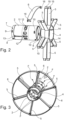
- FIG. 1 shows a perspective view of a membrane holder 1 according to the invention.
- the membrane holder 1 has a central pipe 2 and holding elements 3 arranged around the central pipe 2 and spaced apart in axial direction.
- Each holding element 3 has a ring shaped deflector plate 4 with radially extending wall parts 5. Closing parts 6 are coupled to the free ends of the wall parts 5.
- FIG. 2 shows an exploded view of the parts composing the membrane holder 1 of figure 1 .
- the central pipe 1 is composed out of pipe parts, which have on one end a cylindrical portion 7 which corresponds with the diameter of the inner wall 8 of the other end.
- the cylindrical portion 7 is provided with notches 9 which cooperate with grooves 10 of the other end on the inner wall 8 to provide a snap connection between pipe parts to compose the central pipe 2.
- the pipe part 2 is provided with a band 11 of inlet openings 12, which discharge filtered liquid into the central pipe 2. Furthermore a axially extending groove 13 is arranged in the outer surface of the pipe part 2. This groove 13 cooperates with ribs 14 arranged on the inside of the ring shaped deflector plates 4. The ribs 14 ensure that the inner surface of the deflector plates 4 are at an equally spaced distance from the outside surface of the pipe part 2.
- the free ends of the wall parts 5 are provided with a pair of cylindrical bushings 15, which are coaxially aligned. These bushings 15 couple with pins 16 which are arranged on both ends of the closing part 6 and provide a hinge.
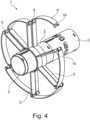
- Figure 3 shows the parts of figure 2 assembled in combination with a second pipe part 2.
- a liquid flow F will be fed into the central pipe part 2. If no deflector plate is present (as shown on the second pipe part), the liquid will flow radially out of the pipe part 2. However, with the ring shaped deflector plate 4 positioned to cover the inlet openings 12, the liquid flow F will be deflected and flow out of the space between the pipe part 2 and deflector plate 4 in axial direction such that hollow fibre membranes held in bundles between the wall parts 5 and closing parts 6 are not damaged.
Landscapes
- Chemical & Material Sciences (AREA)
- Chemical Kinetics & Catalysis (AREA)
- Separation Using Semi-Permeable Membranes (AREA)
- Filtration Of Liquid (AREA)
Claims (9)
- Membranhalterung (1) für Hohlfasermembranen, insbesondere zum Anwenden in einem Röhrchenfilter, umfassend- ein Zentralrohr (2), das voneinander beabstandete Bänder (11) von Einlassöffnungen (12), die entlang eines Umfangs des Zentralrohrs (2) ausgebildet sind, aufweist, um Flüssigkeit durch das Zentralrohr (2) fließen zu lassen;- Halteelemente (3), die um das Zentralrohr (2) angeordnet sind, wobei die Halteelemente (3) sich radial erstreckende Wandteile (5), die entlang des Umfangs des Zentralrohrs (2) verteilt sind, und Verschlussteile (6) aufweisen, die sich zwischen den freien Enden der sich radial erstreckenden Wandteile (5) erstrecken, zum Einschließen eines Bündels von Hohlfasermembranen zwischen zwei angrenzenden sich radial erstreckenden Wandteilen (5) und einem Verschlussteil (6); gekennzeichnet durchAblenkbleche (4), die um das Zentralrohr (2) konzentrisch und beabstandet davon angeordnet sind und in radialer Richtung betrachtet die Bänder (11) der Einlassöffnungen (12) abdecken.
- Membranhalterung (1) nach Anspruch 1, wobei die Ablenkbleche (4) ringförmig sind, und wobei die Innenwand (8) in gleichem Abstand von der Außenoberfläche des Zentralrohrs (2) positioniert ist.
- Membranhalterung (1) nach Anspruch 2, wobei die sich radial erstreckenden Wandteile (5) eines Halteelements (3) zu einem jeweiligen ringförmigen Ablenkblech (4) angeordnet sind.
- Membranhalter (1) nach einem der vorstehenden Ansprüche, wobei das Zentralrohr (2) aus identischen Rohrteilen, die jedes mindestens eines der Bänder (11) von Einlassöffnungen (12) aufweisen, zusammengesetzt ist.
- Membranhalterung (1) nach Anspruch 4, wobei ein Ende jedes Rohrteils einen zylindrischen Abschnitt (7) mit einem Außendurchmesser, der dem Innendurchmesser des anderen Endes des Rohrteils entspricht, aufweist.
- Membranhalterung (1) nach Anspruch 5 und 3, wobei mindestens ein ringförmiges Ablenkblech (4) auf jedem Rohrteil angeordnet ist, und wobei eine längs verlaufende Führungsnut auf einer der Innenoberfläche des ringförmigen Ablenkblechs (4) und der Außenoberfläche des Rohrteils angeordnet ist, wobei eine Rippe auf der anderen Innenoberfläche des ringförmigen Ablenkblechs (4) und der Außenoberfläche des Rohrteils angeordnet ist, und wobei sich die Rippe in die Führungsnut erstreckt.
- Membranhalterung (1) nach einem der vorstehenden Ansprüche, wobei jedes freie Ende der sich radial erstreckenden Wandteile (5) zwei Kopplungsstücke umfasst, und wobei jedes Verschlussteil (6) auf jedem Ende ein Verschlussstück umfasst, wobei ein Verschlussstück eines Wandteils (5) und ein Verschlussstück des Verschlussteils (6) ein Scharnier bereitstellen, dessen Scharnierachse parallel zu der Achse eines Zentralröhrchens ist.
- Membranhalterung (1) nach Anspruch 7, wobei die beiden Kopplungsstücke auf dem freien Ende der sich radial erstreckenden Wand koaxial zueinander angeordnet sind.
- Membranmodul, umfassend:- eine Membranhalterung (1) nach einem der vorstehenden Ansprüche;- Bündel von Hohlfasermembranen, die zwischen je zwei angrenzenden sich radial erstreckenden Wandteilen (5) und einem Verschlussteil (6) angeordnet sind, wobei sich die Bündel zu dem Zentralrohr (2) parallel erstrecken;- mindestens einen Verteiler, der zu einem Ende der Bündel von Hohlfasermembranen angeordnet ist, um den Hohlfasermembranen eine Flüssigkeit, wie etwa Wasser, zuzuführen;- ein Verschlussstück, das zu dem anderen Ende der Bündel von Hohlfasermembranen zum Verschließen jeder Hohlfasermembran angeordnet ist; und- ein Gehäuse, das zwischen dem mindestens einen Verteiler und dem Verschlussstück angeordnet ist, wobei sich das Zentralrohr (2) durch mindestens eines des Verschlussstücks oder mindestens eines des Verteilers erstreckt, um gefilterte Flüssigkeit abzulassen.
Priority Applications (7)
| Application Number | Priority Date | Filing Date | Title |
|---|---|---|---|
| EP21173853.9A EP4088809B1 (de) | 2021-05-14 | 2021-05-14 | Membranhalter und membranmodul |
| JP2023570364A JP2024517352A (ja) | 2021-05-14 | 2022-05-05 | メンブレンホルダおよびメンブレンモジュール |
| US18/559,463 US20240238730A1 (en) | 2021-05-14 | 2022-05-05 | Membrane holder and membrane module |
| AU2022273827A AU2022273827B2 (en) | 2021-05-14 | 2022-05-05 | Membrane holder and membrane module |
| PCT/EP2022/062214 WO2022238243A1 (en) | 2021-05-14 | 2022-05-05 | Membrane holder and membrane module |
| KR1020237042958A KR20240007672A (ko) | 2021-05-14 | 2022-05-05 | 멤브레인 홀더 및 멤브레인 모듈 |
| CN202280034737.8A CN117580634A (zh) | 2021-05-14 | 2022-05-05 | 膜保持器和膜模块 |
Applications Claiming Priority (1)
| Application Number | Priority Date | Filing Date | Title |
|---|---|---|---|
| EP21173853.9A EP4088809B1 (de) | 2021-05-14 | 2021-05-14 | Membranhalter und membranmodul |
Publications (3)
| Publication Number | Publication Date |
|---|---|
| EP4088809A1 EP4088809A1 (de) | 2022-11-16 |
| EP4088809C0 EP4088809C0 (de) | 2025-04-09 |
| EP4088809B1 true EP4088809B1 (de) | 2025-04-09 |
Family
ID=75936729
Family Applications (1)
| Application Number | Title | Priority Date | Filing Date |
|---|---|---|---|
| EP21173853.9A Active EP4088809B1 (de) | 2021-05-14 | 2021-05-14 | Membranhalter und membranmodul |
Country Status (7)
| Country | Link |
|---|---|
| US (1) | US20240238730A1 (de) |
| EP (1) | EP4088809B1 (de) |
| JP (1) | JP2024517352A (de) |
| KR (1) | KR20240007672A (de) |
| CN (1) | CN117580634A (de) |
| AU (1) | AU2022273827B2 (de) |
| WO (1) | WO2022238243A1 (de) |
Families Citing this family (3)
| Publication number | Priority date | Publication date | Assignee | Title |
|---|---|---|---|---|
| US20240318617A1 (en) * | 2023-03-24 | 2024-09-26 | Hamilton Sundstrand Corporation | Membrane deoxygenation with enhanced structural integrity |
| EP4556106A1 (de) | 2023-11-17 | 2025-05-21 | JB Ventures B.V. | Modularer membranhalter für hohlfasermembranen |
| WO2026015215A1 (en) * | 2024-07-08 | 2026-01-15 | Pall Corporation | Hollow fiber alignment devices, systems, and hollow fiber filter devices |
Family Cites Families (3)
| Publication number | Priority date | Publication date | Assignee | Title |
|---|---|---|---|---|
| US6183639B1 (en) * | 1999-09-28 | 2001-02-06 | Hydranautics | Hollow fiber filter module and method of manufacturing same |
| US20070095741A1 (en) * | 2003-10-31 | 2007-05-03 | Berends Hendrik Johan F | Filter module |
| CN2889469Y (zh) | 2006-03-16 | 2007-04-18 | 上海立昇净水设备有限公司 | 带有固定结构的中空纤维膜组件 |
-
2021
- 2021-05-14 EP EP21173853.9A patent/EP4088809B1/de active Active
-
2022
- 2022-05-05 AU AU2022273827A patent/AU2022273827B2/en active Active
- 2022-05-05 WO PCT/EP2022/062214 patent/WO2022238243A1/en not_active Ceased
- 2022-05-05 US US18/559,463 patent/US20240238730A1/en active Pending
- 2022-05-05 CN CN202280034737.8A patent/CN117580634A/zh active Pending
- 2022-05-05 JP JP2023570364A patent/JP2024517352A/ja active Pending
- 2022-05-05 KR KR1020237042958A patent/KR20240007672A/ko active Pending
Also Published As
| Publication number | Publication date |
|---|---|
| AU2022273827A1 (en) | 2023-11-23 |
| EP4088809C0 (de) | 2025-04-09 |
| CN117580634A (zh) | 2024-02-20 |
| US20240238730A1 (en) | 2024-07-18 |
| JP2024517352A (ja) | 2024-04-19 |
| KR20240007672A (ko) | 2024-01-16 |
| EP4088809A1 (de) | 2022-11-16 |
| AU2022273827B2 (en) | 2025-12-18 |
| WO2022238243A1 (en) | 2022-11-17 |
Similar Documents
| Publication | Publication Date | Title |
|---|---|---|
| US20240238730A1 (en) | Membrane holder and membrane module | |
| US6183639B1 (en) | Hollow fiber filter module and method of manufacturing same | |
| US20050121381A1 (en) | Filter disc with panel sectors | |
| EP0771582A1 (de) | Filtergeräte und Endkappen für Filtergeräte | |
| EP0338501A2 (de) | Montageverschluss für eine Querstrom-Filtrationsvorrichtung | |
| US5292298A (en) | Heat transfer roll | |
| JPH01500649A (ja) | 中空繊維フィルタ・カートリッジ及びヘッド | |
| US6203699B1 (en) | Filtration membrane module | |
| EP3057677B1 (de) | Endkappe für filtrationsmodul, filtrationsmodul und filtrationssystem | |
| US4834172A (en) | Heat exchanger | |
| CN210410231U (zh) | 超滤膜过滤器和净水系统 | |
| EP3669813B1 (de) | Wagen mit integriertem mikrofiltrationssystem zum waschen und desinfizieren von medizinischen artikeln | |
| EP4526012B1 (de) | Filtersystem und filterelement | |
| US2936075A (en) | Filter | |
| PL238920B1 (pl) | Podzespół końcowy do zespołu filtracyjnego, zespół filtracyjny filtru i filtr oraz sposób wytwarzania filtru | |
| DE3202330C2 (de) | Im wesentlichen symmetrisch aufgebautes zweiteiliges Filtergehäuse aus Kunststoff | |
| CA2601066C (en) | Membrane module comprising self-supporting, replaceable filter cartridge | |
| NZ527090A (en) | Flat water hose coiler | |
| EP4556106A1 (de) | Modularer membranhalter für hohlfasermembranen | |
| EP1105200B1 (de) | Filteranordnungen | |
| CN215742263U (zh) | 复合滤芯组件和具有其的净水机 | |
| DK1779915T4 (en) | Supporting basket for filter hoses | |
| EP0832675B1 (de) | Filter mit in einem schwenkbaren Gehäuse angeordneten Filterscheiben | |
| EP4331704B1 (de) | Duschfilter, duschmischer und wasserhahn | |
| CN212523683U (zh) | 一种有机管式膜组件 |
Legal Events
| Date | Code | Title | Description |
|---|---|---|---|
| PUAI | Public reference made under article 153(3) epc to a published international application that has entered the european phase |
Free format text: ORIGINAL CODE: 0009012 |
|
| STAA | Information on the status of an ep patent application or granted ep patent |
Free format text: STATUS: THE APPLICATION HAS BEEN PUBLISHED |
|
| AK | Designated contracting states |
Kind code of ref document: A1 Designated state(s): AL AT BE BG CH CY CZ DE DK EE ES FI FR GB GR HR HU IE IS IT LI LT LU LV MC MK MT NL NO PL PT RO RS SE SI SK SM TR |
|
| STAA | Information on the status of an ep patent application or granted ep patent |
Free format text: STATUS: REQUEST FOR EXAMINATION WAS MADE |
|
| 17P | Request for examination filed |
Effective date: 20230404 |
|
| RBV | Designated contracting states (corrected) |
Designated state(s): AL AT BE BG CH CY CZ DE DK EE ES FI FR GB GR HR HU IE IS IT LI LT LU LV MC MK MT NL NO PL PT RO RS SE SI SK SM TR |
|
| STAA | Information on the status of an ep patent application or granted ep patent |
Free format text: STATUS: EXAMINATION IS IN PROGRESS |
|
| 17Q | First examination report despatched |
Effective date: 20230725 |
|
| GRAP | Despatch of communication of intention to grant a patent |
Free format text: ORIGINAL CODE: EPIDOSNIGR1 |
|
| STAA | Information on the status of an ep patent application or granted ep patent |
Free format text: STATUS: GRANT OF PATENT IS INTENDED |
|
| INTG | Intention to grant announced |
Effective date: 20241126 |
|
| GRAS | Grant fee paid |
Free format text: ORIGINAL CODE: EPIDOSNIGR3 |
|
| GRAA | (expected) grant |
Free format text: ORIGINAL CODE: 0009210 |
|
| STAA | Information on the status of an ep patent application or granted ep patent |
Free format text: STATUS: THE PATENT HAS BEEN GRANTED |
|
| AK | Designated contracting states |
Kind code of ref document: B1 Designated state(s): AL AT BE BG CH CY CZ DE DK EE ES FI FR GB GR HR HU IE IS IT LI LT LU LV MC MK MT NL NO PL PT RO RS SE SI SK SM TR |
|
| REG | Reference to a national code |
Ref country code: GB Ref legal event code: FG4D |
|
| REG | Reference to a national code |
Ref country code: CH Ref legal event code: EP |
|
| REG | Reference to a national code |
Ref country code: IE Ref legal event code: FG4D |
|
| U01 | Request for unitary effect filed |
Effective date: 20250416 |
|
| U07 | Unitary effect registered |
Designated state(s): AT BE BG DE DK EE FI FR IT LT LU LV MT NL PT RO SE SI Effective date: 20250424 |
|
| U20 | Renewal fee for the european patent with unitary effect paid |
Year of fee payment: 5 Effective date: 20250527 |
|
| PGFP | Annual fee paid to national office [announced via postgrant information from national office to epo] |
Ref country code: GB Payment date: 20250527 Year of fee payment: 5 |
|
| PG25 | Lapsed in a contracting state [announced via postgrant information from national office to epo] |
Ref country code: ES Free format text: LAPSE BECAUSE OF FAILURE TO SUBMIT A TRANSLATION OF THE DESCRIPTION OR TO PAY THE FEE WITHIN THE PRESCRIBED TIME-LIMIT Effective date: 20250409 |
|
| PG25 | Lapsed in a contracting state [announced via postgrant information from national office to epo] |
Ref country code: GR Free format text: LAPSE BECAUSE OF FAILURE TO SUBMIT A TRANSLATION OF THE DESCRIPTION OR TO PAY THE FEE WITHIN THE PRESCRIBED TIME-LIMIT Effective date: 20250710 Ref country code: NO Free format text: LAPSE BECAUSE OF FAILURE TO SUBMIT A TRANSLATION OF THE DESCRIPTION OR TO PAY THE FEE WITHIN THE PRESCRIBED TIME-LIMIT Effective date: 20250709 |
|
| PG25 | Lapsed in a contracting state [announced via postgrant information from national office to epo] |
Ref country code: PL Free format text: LAPSE BECAUSE OF FAILURE TO SUBMIT A TRANSLATION OF THE DESCRIPTION OR TO PAY THE FEE WITHIN THE PRESCRIBED TIME-LIMIT Effective date: 20250409 |
|
| PG25 | Lapsed in a contracting state [announced via postgrant information from national office to epo] |
Ref country code: HR Free format text: LAPSE BECAUSE OF FAILURE TO SUBMIT A TRANSLATION OF THE DESCRIPTION OR TO PAY THE FEE WITHIN THE PRESCRIBED TIME-LIMIT Effective date: 20250409 |
|
| PG25 | Lapsed in a contracting state [announced via postgrant information from national office to epo] |
Ref country code: RS Free format text: LAPSE BECAUSE OF FAILURE TO SUBMIT A TRANSLATION OF THE DESCRIPTION OR TO PAY THE FEE WITHIN THE PRESCRIBED TIME-LIMIT Effective date: 20250709 |
|
| PG25 | Lapsed in a contracting state [announced via postgrant information from national office to epo] |
Ref country code: IS Free format text: LAPSE BECAUSE OF FAILURE TO SUBMIT A TRANSLATION OF THE DESCRIPTION OR TO PAY THE FEE WITHIN THE PRESCRIBED TIME-LIMIT Effective date: 20250809 |
|
| REG | Reference to a national code |
Ref country code: CH Ref legal event code: H13 Free format text: ST27 STATUS EVENT CODE: U-0-0-H10-H13 (AS PROVIDED BY THE NATIONAL OFFICE) Effective date: 20251223 |
|
| PG25 | Lapsed in a contracting state [announced via postgrant information from national office to epo] |
Ref country code: SM Free format text: LAPSE BECAUSE OF FAILURE TO SUBMIT A TRANSLATION OF THE DESCRIPTION OR TO PAY THE FEE WITHIN THE PRESCRIBED TIME-LIMIT Effective date: 20250409 |
|
| PG25 | Lapsed in a contracting state [announced via postgrant information from national office to epo] |
Ref country code: CH Free format text: LAPSE BECAUSE OF NON-PAYMENT OF DUE FEES Effective date: 20250531 |
|
| PG25 | Lapsed in a contracting state [announced via postgrant information from national office to epo] |
Ref country code: CZ Free format text: LAPSE BECAUSE OF FAILURE TO SUBMIT A TRANSLATION OF THE DESCRIPTION OR TO PAY THE FEE WITHIN THE PRESCRIBED TIME-LIMIT Effective date: 20250409 |
|
| PG25 | Lapsed in a contracting state [announced via postgrant information from national office to epo] |
Ref country code: SK Free format text: LAPSE BECAUSE OF FAILURE TO SUBMIT A TRANSLATION OF THE DESCRIPTION OR TO PAY THE FEE WITHIN THE PRESCRIBED TIME-LIMIT Effective date: 20250409 |
|
| PG25 | Lapsed in a contracting state [announced via postgrant information from national office to epo] |
Ref country code: MC Free format text: LAPSE BECAUSE OF FAILURE TO SUBMIT A TRANSLATION OF THE DESCRIPTION OR TO PAY THE FEE WITHIN THE PRESCRIBED TIME-LIMIT Effective date: 20250409 |
|
| PLBE | No opposition filed within time limit |
Free format text: ORIGINAL CODE: 0009261 |
|
| STAA | Information on the status of an ep patent application or granted ep patent |
Free format text: STATUS: NO OPPOSITION FILED WITHIN TIME LIMIT |