EP4331704B1 - Duschfilter, duschmischer und wasserhahn - Google Patents
Duschfilter, duschmischer und wasserhahn Download PDFInfo
- Publication number
- EP4331704B1 EP4331704B1 EP23193739.2A EP23193739A EP4331704B1 EP 4331704 B1 EP4331704 B1 EP 4331704B1 EP 23193739 A EP23193739 A EP 23193739A EP 4331704 B1 EP4331704 B1 EP 4331704B1
- Authority
- EP
- European Patent Office
- Prior art keywords
- filter
- outer sleeve
- space
- wall
- axis
- Prior art date
- Legal status (The legal status is an assumption and is not a legal conclusion. Google has not performed a legal analysis and makes no representation as to the accuracy of the status listed.)
- Active
Links
Images


Classifications
-
- B—PERFORMING OPERATIONS; TRANSPORTING
- B01—PHYSICAL OR CHEMICAL PROCESSES OR APPARATUS IN GENERAL
- B01D—SEPARATION
- B01D35/00—Filtering devices having features not specifically covered by groups B01D24/00 - B01D33/00, or for applications not specifically covered by groups B01D24/00 - B01D33/00; Auxiliary devices for filtration; Filter housing constructions
- B01D35/02—Filters adapted for location in special places, e.g. pipe-lines, pumps, stop-cocks
- B01D35/04—Plug, tap, or cock filters filtering elements mounted in or on a faucet
-
- E—FIXED CONSTRUCTIONS
- E03—WATER SUPPLY; SEWERAGE
- E03C—DOMESTIC PLUMBING INSTALLATIONS FOR FRESH WATER OR WASTE WATER; SINKS
- E03C1/00—Domestic plumbing installations for fresh water or waste water; Sinks
- E03C1/02—Plumbing installations for fresh water
- E03C1/021—Devices for positioning or connecting of water supply lines
- E03C1/023—Devices for positioning or connecting of water supply lines with flow distribution, e.g. diverters
-
- B—PERFORMING OPERATIONS; TRANSPORTING
- B01—PHYSICAL OR CHEMICAL PROCESSES OR APPARATUS IN GENERAL
- B01D—SEPARATION
- B01D35/00—Filtering devices having features not specifically covered by groups B01D24/00 - B01D33/00, or for applications not specifically covered by groups B01D24/00 - B01D33/00; Auxiliary devices for filtration; Filter housing constructions
- B01D35/30—Filter housing constructions
-
- C—CHEMISTRY; METALLURGY
- C02—TREATMENT OF WATER, WASTE WATER, SEWAGE, OR SLUDGE
- C02F—TREATMENT OF WATER, WASTE WATER, SEWAGE, OR SLUDGE
- C02F1/00—Treatment of water, waste water, or sewage
- C02F1/001—Processes for the treatment of water whereby the filtration technique is of importance
-
- C—CHEMISTRY; METALLURGY
- C02—TREATMENT OF WATER, WASTE WATER, SEWAGE, OR SLUDGE
- C02F—TREATMENT OF WATER, WASTE WATER, SEWAGE, OR SLUDGE
- C02F1/00—Treatment of water, waste water, or sewage
- C02F1/001—Processes for the treatment of water whereby the filtration technique is of importance
- C02F1/003—Processes for the treatment of water whereby the filtration technique is of importance using household-type filters for producing potable water, e.g. pitchers, bottles, faucet mounted devices
-
- C—CHEMISTRY; METALLURGY
- C02—TREATMENT OF WATER, WASTE WATER, SEWAGE, OR SLUDGE
- C02F—TREATMENT OF WATER, WASTE WATER, SEWAGE, OR SLUDGE
- C02F2201/00—Apparatus for treatment of water, waste water or sewage
- C02F2201/002—Construction details of the apparatus
- C02F2201/006—Cartridges
-
- C—CHEMISTRY; METALLURGY
- C02—TREATMENT OF WATER, WASTE WATER, SEWAGE, OR SLUDGE
- C02F—TREATMENT OF WATER, WASTE WATER, SEWAGE, OR SLUDGE
- C02F2307/00—Location of water treatment or water treatment device
- C02F2307/06—Mounted on or being part of a faucet, shower handle or showerhead
Definitions
- the present invention relates to a shower filter and more particularly to a shower filter according to preamble of claim 1.
- the present invention further relates to a shower head and more particularly to a shower mixer according to preamble of claim 14.
- the present invention also relates to a faucet and more particularly to a faucet according to preamble of claim 15.
- the shower filter comprises a water inlet, water outer and a filter cartridge comprising one or more filters or filter layers.
- the filter cartridge is provided between the water inlet and the water outlet such that water flows linearly through the one or more filters or filter layers of the filter cartridge.
- the filter cartridge and the one or more filters or filter layers are usually arranged directly between the water inlet and the water outlet.
- the filter cartridge is arranged offset from the linear direction between the water inlet and the water outlet.
- the water inlet is provided with inlet tube extending from the water inlet to a bottom of the filter cartridge. The water then flows through the one or more filters or filter layers linearly to the water outlet.
- Patent document KR20180057852A discloses a filter for sterilizing water by receiving raw water, primary filtering to remove foreign matter, removing chemical by-products by chlorination, and secondary filtering by adding moisturising and vitamin components.
- An object of the present invention is to provide a shower filter, shower mixer and faucet such that prior art disadvantages are solved or at least alleviated.
- the objects of the invention are achieved by a shower filter which is characterized by what is stated in the independent claim 1.
- the objects of the invention are further achieved by a shower mixer which is characterized by what is stated in the independent claim 14.
- the objects of the invention are also achieved by a faucet which is characterized by what is stated in the independent claim 15.
- the present invention is based on an idea of providing a shower filter, the shower filter comprising a filter body having a first flow channel and a second flow channel. Water is arranged to flow into and from the shower filter via the first and second flow channels.
- the filter body comprises an outer sleeve having a first outer sleeve end, a second outer sleeve end and an outer sleeve wall extending between the first and second outer sleeve ends.
- the first outer sleeve end comprises a first outer sleeve opening
- the second outer sleeve end comprises a second outer sleeve opening.
- the outer sleeve may be provided as any kind of chamber having the first outer sleeve opening in the first outer sleeve end and the second outer sleeve opening in the second outer sleeve end.
- the filter body further comprises an inner sleeve having a first inner sleeve end, a second inner sleeve end and an inner sleeve wall extending between the first and second inner sleeve ends.
- the inner sleeve wall is arranged define an inner body space inside the inner sleeve.
- the first inner sleeve end comprises a first inner sleeve opening
- the second inner sleeve end comprises a second inner sleeve opening.
- the inner sleeve may be provided as any kind of chamber having the first inner sleeve opening in the first inner sleeve end and the second inner sleeve opening in the second inner sleeve end.
- the inner sleeve is arranged inside the outer sleeve, and an intermediate body space is provided between the outer sleeve wall of the outer sleeve and the inner sleeve wall of the inner sleeve.
- the intermediate body space is provided between the outer sleeve and the inner sleeve.
- the shower filter further comprises a first filter cartridge provided in connection with filter body at the first outer sleeve end and the first inner sleeve end.
- the first filter cartridge is arranged in fluid communication with the intermediate body space and the inner body space.
- the first filter cartridge is connected to the filter body such that water flows between the intermediate body space and the inner body space via the first filter cartridge.
- the shower filter further comprises a second filter cartridge provided in connection with filter body at the second outer sleeve end and the second inner sleeve end.
- the second filter cartridge is arranged in fluid communication with the intermediate body space and the inner body space.
- the second filter cartridge is connected to the filter body such that water flows between the intermediate body space and the inner body space via the second filter cartridge.
- the first flow channel is arranged to extend from the outer sleeve wall to the intermediate body space.
- the first flow channel is open to outside of the outer sleeve wall and to the intermediate body space.
- the first flow channel is arranged in fluid communication with the intermediate body space.
- the second flow channel is arranged to extend from the outer sleeve wall to the inner body space.
- the second flow channel is open to outside the outer sleeve wall and inside the inner body space.
- the second flow channel is arranged in fluid communication with the inner body space.
- the first and second filter cartridges are arranged on opposite ends of the filter body.
- the present invention provides a shower filter in which water is arranged to flow from the first flow channel into the intermediate body space and from the intermediate body space to the first and second filter cartridges. Then the water is further arranged to flow from the first and second filter cartridges into the inner body space, and from the inner body space to the second flow channel.
- the present invention provides a shower filter in which water is arranged to flow from the second flow channel into the inner body space and from the inner body space to the first and second filter cartridges. Then the water is further arranged to flow from the first and second filter cartridges into the intermediate body space, and from the intermediate body space to the first flow channel.
- the water flowing into the shower filter is divided into both the first and second filter cartridges to be filtered.
- the retention time of the water inside the filter is increased.
- the outer dimension of the shower filter is kept small as the first and second filter cartridges are arranged on opposite ends of the filter body.
- the first and second filter cartridges comprise a filter container and a filter element provided inside the filter container.
- the filter cartridge comprises inside the filter container a first cartridge space and a second cartridge space.
- the filter element is arranged to separate the first cartridge space and the second cartridge space inside the filter container.
- the first cartridge space is arranged in fluid communication with the intermediate body space, and the second cartridge space is arranged in fluid communication with the inner body space.
- the water is arranged to flow through the filter element.
- Water is arranged to flow through the filter element as it flows from the intermediate body space to the inner body space, or from the inner body space to the intermediate body space.
- the outer sleeve is arranged to surround the inner sleeve and the intermediate body space is arranged between the outer sleeve wall and the inner sleeve wall.
- the outer sleeve has an outer sleeve axis
- the inner sleeve has an inner sleeve axis.
- the outer sleeve is arranged to surround the inner sleeve
- the intermediate body space is arranged between the outer sleeve wall and the inner sleeve wall such that the outer sleeve axis and the inner sleeve axis are parallel to each other.
- the outer sleeve and the inner sleeve are arranged parallel to each other.
- the first and second filter cartridges are provided on opposite ends to the filter body and opposite to each other.
- the outer sleeve has an outer sleeve axis
- the inner sleeve has an inner sleeve axis.
- the outer sleeve is arranged to surround the inner sleeve
- the intermediate body space is arranged between the outer sleeve wall and the inner sleeve wall such that the outer sleeve axis and the inner sleeve axis are parallel and concentric with each other.
- the outer sleeve and the inner sleeve are arranged parallel to each other.
- the first and second filter cartridges are provided on opposite ends to the filter body and opposite to each other and the intermediate body space is uniform between the outer sleeve and the inner sleeve.
- the first outer sleeve opening of the first outer sleeve end is arranged open to the intermediate body space
- the second outer sleeve opening of the second outer sleeve end is arranged open to the intermediate body space.
- the first outer sleeve opening is in fluid communication with the intermediate body space
- the second outer sleeve is in fluid communication with the intermediate body space. Therefore, water is arranged to flow from the intermediate body to the first and second outer sleeve openings. Alternatively, water is arranged to flow from the first and second outer sleeve openings to the intermediate body space.
- the first inner sleeve opening of the first inner sleeve end is arranged open to the inner body space, and the second inner sleeve opening of the second inner sleeve end is arranged open to the inner body space.
- the first inner sleeve opening is in fluid communication with the inner body space, and the second inner sleeve is in fluid communication with the inner body space.
- the first flow channel is arranged to the outer sleeve wall and arranged extend through the outer sleeve wall to the intermediate body space.
- the second flow channel is arranged to the outer sleeve wall and arranged to extend through the outer sleeve wall, through the intermediate body space and through the inner sleeve wall to the inner body space.
- the first flow channel is in direct fluid communication with the intermediate body space.
- the first flow channel is not in direct fluid communication with the inner body space.
- the first flow channel is separated or separate from the inner body space by the inner sleeve wall.
- the second flow channel is in direct fluid communication with the inner body space.
- the second flow channel is not in direct fluid communication with the intermediate body space.
- the second flow channel is separated or separate from intermediate body space by the second flow channel extending through the intermediate body space.
- the inner sleeve is supported to the outer sleeve.
- the inner sleeve is supported to outer sleeve with one or more connection elements.
- the inner sleeve is supported to outer sleeve with one or more connection elements extending between the inner sleeve and the outer sleeve in the intermediate body space.
- the inner sleeve is arranged inside the outer sleeve and supported to the outer sleeve. Therefore, the position of the inner sleeve is fixed in relation to the outer sleeve.
- the filter body comprises a connection wall extending between the inner sleeve and the outer sleeve in the intermediate body space.
- the inner sleeve is supported to the outer sleeve with the connection wall extending in the intermediate body space.
- the filter body comprises a connection wall extending between the inner sleeve and the outer sleeve in the intermediate body space.
- the connection wall comprises one or more wall openings extending through the connection wall and open to both sides of the connection wall.
- the one or more wall openings enable water flow through the connection wall.
- the first flow channel is arranged to open on both sides of the connection wall and into the intermediate body space.
- water is arranged flow from the first flow channel into the intermediate space on both side of the connection wall.
- water is arranged flow from the intermediate space on both side of the connection wall to the first flow channel.
- the filter body comprises a first and a second connection walls extending between the inner sleeve and the outer sleeve in the intermediate body space.
- the first and a second connection walls are arranged spaced apart from each other in the intermediate body space such that a connection wall space is provided between the first and second connection walls in the intermediate body space.
- Utilizing the first and second connection walls provides rigidity to the structure of the filter body and the shower filter.
- the filter body comprises a first and a second connection walls extending between the inner sleeve and the outer sleeve in the intermediate body space.
- the first and a second connection walls are arranged spaced apart from each other in the intermediate body space such that a connection wall space is provided between the first and second connection walls in the intermediate body space.
- the first connection wall comprises one or more wall openings extending through the first connection wall and open to both sides of the first connection wall.
- the second connection wall comprises one or more wall openings extending through the second connection wall and open to both sides of the second connection wall.
- the wall openings of the first and second connection walls enable water flow through the first and second connection walls and in and out of the connection wall space.
- the first flow channel is arranged to open into the connection wall space between the first and second connection walls.
- water is arranged to flow from the first flow channel to the connection wall space.
- water is arranged to flow from the connection wall space to the first flow channel.
- the first flow channel is arranged to open into the connection wall space between the first and second connection walls
- the second flow channel is arranged to extend through the outer sleeve wall through the intermediate body space in the connection wall space between the first and second connection walls, and through the inner sleeve wall to the inner body space.
- water is arranged to flow from the first flow channel to the connection wall space.
- water is arranged to flow from the connection wall space to the first flow channel.
- water is arranged to flow inner body space to the second flow channel, or from the second flow channel to the inner body space.
- the second flow channel is not open to the intermediate body space.
- the first flow channel and the second flow channel extend parallel to each other.
- the outer sleeve has the outer sleeve axis
- the first flow channel comprises a first channel axis.
- the first longitudinal channel axis is arranged to extend perpendicularly to the outer sleeve axis
- the second flow channel comprises a second channel axis, the second longitudinal channel axis is arranged to extend perpendicularly to the outer sleeve axis.
- the outer sleeve has the outer sleeve axis
- the first flow channel comprises a first channel axis.
- the first longitudinal channel axis is arranged to extend perpendicularly to the outer sleeve axis
- the second flow channel comprises a second channel axis
- the second longitudinal channel axis is arranged to extend perpendicularly to the outer sleeve axis
- the first and second channel axes are arranged parallel and concentric with each other.
- the outer sleeve has the outer sleeve axis
- the first flow channel comprises a first channel axis.
- the first longitudinal channel axis is arranged to extend perpendicularly to the outer sleeve axis and cross the outer sleeve axis
- the second flow channel comprises a second channel axis
- the second longitudinal channel axis is arranged to extend perpendicularly to the outer sleeve axis and cross the outer sleeve axis.
- the outer sleeve has the outer sleeve axis
- the first flow channel comprises a first channel axis.
- the first longitudinal channel axis is arranged to extend perpendicularly to the outer sleeve axis and spaced apart from the outer sleeve axis
- the second flow channel comprises a second channel axis
- the second longitudinal channel axis is arranged to extend perpendicularly to the outer sleeve axis and cross the outer sleeve axis.
- the outer sleeve has the outer sleeve axis
- the first flow channel comprises a first channel axis.
- the first longitudinal channel axis is arranged to extend perpendicularly to the outer sleeve axis and cross the outer sleeve axis
- the second flow channel comprises a second channel axis
- the second longitudinal channel axis is arranged to extend perpendicularly to the outer sleeve axis and spaced apart from the outer sleeve axis.
- the filter element is formed as a hollow cylindrical filter element having a hollow cylinder space inside the cylindrical filter element, the hollow cylinder space is arranged to form the second cartridge space.
- the filter container comprises filter container walls, the first cartridge space is formed between the filter container walls and the hollow cylindrical filter element.
- water flows through walls of the cylindrical filter element.
- water flows from the first cartridge space between the between the filter container walls through the filter element and the hollow cylindrical filter element into the second cartridge space inside the hollow cylindrical filter element.
- water flows from the hollow cylinder space through the filter element and to the first cartridge space between the between the filter container walls through the filter element.
- the filter element is formed as a hollow cylindrical filter element having a hollow cylinder space inside the cylindrical filter element, the hollow cylinder space is arranged to form the second cartridge space.
- the filter container is formed as a cylindrical filter container having a container space inside the filter container, a bottom wall, an open front end, and a sheath wall extending between the bottom wall and the open front end, and the first cartridge space is formed between the sheath wall and the hollow cylindrical filter element.
- the filter element comprises a cylindrical filter having a first filter end and a second filter end.
- the cylindrical filter comprises a hollow filter space inside the cylindrical filter between the first and second filter ends.
- the hollow filter space is arranged to form at least part of the second cartridge space, and the first filter end is provided with an end cap arranged to close the hollow filter space at the first filter end.
- the filter element comprises a cylindrical filter having a first filter end and a second filter end.
- the cylindrical filter comprises a hollow filter space inside the cylindrical filter between the first and second filter ends.
- the first filter end is provided with an end cap arranged to close the hollow filter space at the first filter end, and the second filter end is provided with a front cap comprising an out flow opening in fluid communication with the hollow filter space, the hollow filter space and the out flow opening together forming the second cartridge space.
- the first filter end of cylindrical filter is arranged against the bottom wall of the cylindrical filter container.
- the end cap is arranged towards the bottom wall of the cylindrical filter container.
- the end cap is arranged against the bottom wall of the cylindrical filter container.
- the end cap or the first filter end is attached to the bottom wall of the cylindrical filter container.
- the first filter cartridge is connected to the filter body, the filter container of the first filter cartridge is connected to the outer sleeve, and the filter element of the first filter cartridge is connected to the inner sleeve.
- the second filter cartridge is connected to the filter body, the filter container of the second filter cartridge is connected to the outer sleeve, and the filter element of the second filter cartridge is connected to the inner sleeve.
- the first filter cartridge is connected to the filter body, the filter container of the first filter cartridge is connected to the first outer sleeve end, and the filter element of the first filter cartridge is connected to the first inner sleeve end, and the second filter cartridge is connected to the filter body, the filter container of the second filter cartridge is connected to the second outer sleeve end, and the filter element of the second filter cartridge is connected to the second inner sleeve end.
- the second filter end of the first filter cartridge is connected to the first inner sleeve end such that the hollow filter space is in fluid communication with the inner body space and the first cartridge space of the first filter cartridge is in fluid communication with the intermediate body space
- the second filter end of the second filter cartridge is connected to the second inner sleeve end such that the hollow filter space is in fluid communication with the inner body space and the first cartridge space of the second filter cartridge is in fluid communication with the intermediate body space
- the front cap of the first filter cartridge is connected to the first inner sleeve end such that the hollow filter space and the out flow opening are in fluid communication with the inner body space and the first cartridge space of the first filter cartridge is in fluid communication with the intermediate body space
- the front cap of the second filter cartridge is connected to the second inner sleeve end such that the hollow filter space and the out flow opening are in fluid communication with the inner body space and the first cartridge space of the second filter cartridge is in fluid communication with the intermediate body space
- the present invention also relates to a faucet comprising a water outlet.
- the faucet is provided with a shower filter as described above.
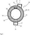
- the filter body 10 also comprises an intermediate body space 59 between outer wall 23 and the inner wall 33.
- the filter body 10 further comprises an inner body space 35 inside the inner wall 33 and the inner wall 30 is arranged define the inner body space 35. Accordingly, the intermediate body space 59 is provided between the outer sleeve 20 and the inner sleeve 30.
- the circumferential inner sleeve has a circular cross-sectional shape.
- the cross-sectional shape may also be elliptical or polygonal.
- the circumferential outer sleeve 20 comprises a first outer sleeve end 40 and a second outer sleeve end 42.
- the outer wall 23 is arranged to extend between the first outer sleeve end 40 and the second outer sleeve end 42, as shown in figure 2 .
- the first outer sleeve end 40 is an open end or comprises a first outer sleeve opening 41.
- the second outer sleeve end 42 is an open end or comprises a second outer sleeve opening 43.
- the first outer sleeve opening 41 is open to the intermediate body space 59.
- the second outer sleeve opening 43 is also open to the intermediate body space 59.
- the first outer sleeve opening 41 is open to the inner body space 35.
- the second outer sleeve opening 43 is also open to the inner body space 35.
- the circumferential outer sleeve 20 is provided with a first body threads 21 at the first outer sleeve end 40.
- the circumferential outer sleeve 20 is provided with a second body threads 22 at the second outer sleeve end 42.
- the first and second body threads 21, 22 are provided preferably as inner threads to the circumferential outer sleeve 20.
- the first and second body threads 21, 22 are provided to the outer wall 23 in connection with the first and second outer sleeve ends 40, 42.
- connection wall(s) 32 extend radially between the circumferential inner sleeve 30 and outer sleeve 20 in the intermediate body space 59.
- connection wall(s) 32 extend between the inner surface of the outer wall 23 and the inner wall 33.
- connection wall(s) 32 may be replaced with connection structure such as connection lattice or connection bars.
- the circumferential inner sleeve 30 comprises a first inner sleeve end 36 and a second inner sleeve end 37.
- the inner wall 33 is arranged to extend between the first inner sleeve end 36 and the second inner sleeve end 37.
- the first inner sleeve end 36 is an open end or comprises a first inner sleeve opening.
- the second inner sleeve end 37 is an open end or comprises a second inner sleeve opening. Accordingly, the first inner sleeve end 36 and the second inner sleeve end 37 are open to the inner body space 35.
- first flow channel 12 is arranged to extend from the outer wall 23 to the intermediate body space 59 between the inner sleeve 30 and the outer sleeve 20. Accordingly, the first flow channel 12 is open to outside of the outer wall 23 and to the intermediate body space 59. Thus, water may flow via the first flow channel 12 from outside the outer sleeve 20 to the intermediate body space 59.
- the first flow channel 12 and the intermediate body space 59 are not in fluid communication with the inner body space 35.
- the second flow channel 16 is arranged to extend from the outer wall 23 to the inner body space 35. Accordingly, the second flow channel 16 is open to outside the outer wall 23 and inside the inner body space 35. Thus, water may from the inner body space 35 via the second flow channel 16 outside the outer sleeve 20.
- the second flow channel 16 is not in fluid communication with the intermediate body space 59.
- the inner sleeve 30 is arranged inside the outer sleeve 20 is arranged inside the outer sleeve 20.
- the inner sleeve 30 comprises smaller diameter than the outer sleeve 20.
- the outer sleeve 20 comprises a longitudinal outer sleeve axis X defined by the outer wall.
- the inner sleeve 30 comprises a longitudinal inner sleeve axis Y defined by the inner wall.
- the inner sleeve 30 is arranged inside the circumferential outer sleeve 20 and arranged such that longitudinal outer sleeve axis X and the longitudinal inner sleeve axis Y are parallel to each other.
- the inner sleeve 30 is arranged inside the outer sleeve 20 is arranged inside the outer sleeve 20 concentrically.
- the intermediate body space 59 is provided a cylindrical space surrounding in uniform manner the circumferential inner sleeve 30.
- the first and a second connection walls 32 are arranged spaced apart from each other in the intermediate body space 59 such that a connection wall space 39 is provided between the first and second connection walls 32 in the intermediate body space 59.
- the first connection wall 32 comprises one or more wall openings 34 extending through the first connection wall 32 and open to both sides of the first connection wall 32.
- the second connection wall 32 comprises one or more wall openings 34 extending through the second connection wall 32 and open to both sides of the second connection wall 32.
- the first flow channel 12 is arranged to open into the connection wall space 39 between the first and second connection walls 32.
- the second flow channel 16 is arranged to extend through the outer sleeve wall 23, through the intermediate body space 59 in the connection wall space 39 between the first and second connection walls 32, and through the inner sleeve wall 33 to the inner body space 35.
- the inner sleeve wall 33 is provided with an inner sleeve opening 61 open to the inner body space 35 and to the second flow channel 16, as shown in figure 3 .
- FIG 4 shows an embodiment, in which there is one connection wall 32.
- the first flow channel 12 opens on both sides of the connection wall 32.
- the connection wall 32 is provided with the wall openings 34.
- the wall opening 34 open to both sides of the connection wall 32 in the intermedia body space 59. Accordingly, the water flows from the first flow channel 12 to the intermediate body space 35 and through the connection wall 32 via the wall opening 34.
- the connection wall 32 is arranged to extend between the inner sleeve 30 and the outer sleeve 20 in the intermediate body space 59.
- first flow channel 12 and the second flow channel 16 are provided parallel to each other and concentric on opposite sides of the circumferential outer sleeve 20.
- the first flow channel 12 comprises a first channel axis Z.
- the first longitudinal channel axis Z is arranged to extend perpendicularly to the outer sleeve axis X.
- the second flow channel 16 comprises a second channel axis Q.
- the second longitudinal channel axis Q is arranged to extend perpendicularly to the outer sleeve axis X.
- the first channel axis Z and the second channel axis Q are arranged to extend perpendicularly to the outer sleeve axis X and cross the outer sleeve axis X.
- the first channel axis Z is arranged to extend perpendicularly to the outer sleeve axis X and spaced apart from the outer sleeve axis X.
- the second channel axis Q is arranged to extend perpendicularly to the outer sleeve axis X and cross the outer sleeve axis X.
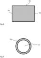
- the shower filter comprises a filter cartridge 100.
- the filter cartridge 100 comprises a filter element 80 arranged inside a filter container 100.
- the filter element 80 comprises filter 70.
- Figures 6 and 7 show a cylindrical filter 70 having a first filter end 72 and a second filter end 74.
- the cylindrical filter 70 comprises a hollow filter space 77 inside the cylindrical filter 70 between the first and second filter ends 72, 74.
- the filter element 80 comprises an end cap 82 and a front cap 84.
- the first filter end 72 is provided with the end cap 82.
- the end cap 82 is arranged to close the hollow filter space 77 at the first filter end.
- the filter 70 is provided as hollow cylindrical filter, as shown in figures 6 and 7 .
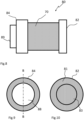
- FIGS 8 to 11 show the filter element 80 comprising the filter 70.
- the second filter end 74 is provided the front cap 84.
- the front cap comprises front end 89 provided with an out flow opening 88.
- the out flow opening 88 is open to the hollow filter space 77 and outside the filter 70.
- the front cap 84 is attached to the second filter end74.
- the first filter end 72 is provided an end cap 82 arranged to close the hollow filter space 77 at the first filter end 72.
- the end cap 82 is attached to the first filter end 72.
- the end cap 82 comprises a bottom wall 81 closing the first filter end 72 and forming bottom of the filter element 80.
- the bottom wall 81 is provided a recess 83 extending towards the hollow filter space 77 from the bottom wall 81.
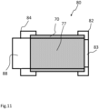
- FIGS. 12 and 13 show the filter container.
- the filter container 102, 104, 106 is formed as a cylindrical filter container having a container space 108 inside the filter container 102, 104, 106, a bottom wall 102, an open front end 104 and a sheath wall 106 extending between the bottom wall 102 and the open front end.
- the filter container or the sheath wall 106 is provided a with container threads 107 in connection with the open front end 104.
- the bottom wall 102 is provided with a protrusion 103 extending into the container space from the bottom wall 102.
- FIG 14 shows the filter cartridge 100 having the filter container 102, 104, 106 inside which the filter element 80 is arranged.
- the filter container 102, 104, 106 is formed as a cylindrical filter container having the container space 108 inside the filter container 102, 104, 106.
- the end cap 82 the filter element 80 is arranged towards the bottom wall 102.
- the end cap 82 is preferably arranged against the bottom wall 102 such that the protrusion 103 of the bottom wall is arranged into the recess 83 of the end cap 82. Accordingly, the filter element 80 is secured to the filter container with the protrusion 103 and the end cap 82.
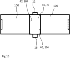
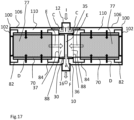
- FIGS 15 , 16 and 17 show the shower filter in assembled form.
- the shower filter comprises a first filter cartridge 100 and a second filter cartridge 100.
- the first filter cartridge 100 comprises a first filter container 102, 104, 106 and a first filter element 80.
- the second filter cartridge 100 comprise a second filter container 102, 104, 106 and a second filter element 80.
- the first filter cartridge 100 is connected to the filter body 10 such that the first filter container 102, 104, 106 is connected to the first outer sleeve end 40 and the first filter element 80 is connected to the first inner sleeve end 36.
- the front cap 84 is connected to the first inner sleeve end 36 such that the hollow filter space 77 and the out flow opening 88 are in fluid communication with the inner body space 35.
- the second cartridge space is in fluid communication with the inner body space 35 and the first cartridge space 110 is in fluid communication with the intermediate body space 59.
- the second filter cartridge 100 is connected to the filter body 10 such that the second filter container 102, 104, 106 is connected to the second outer sleeve end 42, and the second filter element 80 is connected to the second inner sleeve end 37.
- the front cap 84 is connected to the first inner sleeve end 36 such that the hollow filter space 77 and the out flow opening 88 are in fluid communication with the inner body space 35.
- the second cartridge space is in fluid communication with the inner body space and the first cartridge space 110 is in fluid communication with the intermediate body space 59, as shown in figures 16 and 17 .
- Figure 16 comprises a filter body 10 of figure 3 and the figure 17 comprises the filter body 10 of figure 4 .
- water is arranged to enter the shower filter through the first flow channel 12 in direction of arrow I.
- Water enters the intermediate body space 59 from the first flow channel 12 and is arranged to flow to the first cartridge space 110 in direction of arrows C.
- Water is further arranged to flow through the filter 70 into the hollow filter space 77 in direction of arrows D such that water is filtrated.
- Water is arranged to flow from the second cartridge space 77, 88 to the inner body space 35 as shown with arrows E. From the inner body space 35 water is arranged to flow to the second flow channel 16 in direction of arrow F and further as outflow O out of the shower filter.
Landscapes
- Chemical & Material Sciences (AREA)
- Engineering & Computer Science (AREA)
- Water Supply & Treatment (AREA)
- Hydrology & Water Resources (AREA)
- Life Sciences & Earth Sciences (AREA)
- Organic Chemistry (AREA)
- Environmental & Geological Engineering (AREA)
- Chemical Kinetics & Catalysis (AREA)
- Health & Medical Sciences (AREA)
- Public Health (AREA)
- Domestic Plumbing Installations (AREA)
- Nozzles (AREA)
- Bathtubs, Showers, And Their Attachments (AREA)
Claims (15)
- Duschfilter, wobei- der Duschfilter einen Filterkörper (10) umfasst, der einen ersten Strömungskanal (12) und einen zweiten Strömungskanal (16) aufweist;- der Filterkörper (10) eine Außenhülle (20) umfasst, die ein erstes Außenhüllenende (40), ein zweites Außenhüllenende (42) und eine Außenhüllenwand (23) aufweist, die sich zwischen dem ersten und zweiten Außenhüllenende (40, 42) erstreckt;- das erste Außenhüllenende (40) eine erste Außenhüllenöffnung umfasst und das zweite Außenhüllenende (42) eine zweite Außenhüllenöffnung umfasst;- der Filterkörper (10) eine Innenhülle (30) umfasst, die ein erstes Innenhüllenende (36), ein zweites Innenhüllenende (37) und eine Innenhüllenwand (33) aufweist, die sich zwischen dem ersten und zweiten Innenhüllenende (36, 37) erstreckt, wobei die Innenhüllenwand (33) angeordnet ist, um innerhalb der Innenhülle (30) einen Körperinnenraum (35) zu definieren;- das erste Innenhüllenende (36) eine erste Innenhüllenöffnung umfasst, und das zweite Innenhüllenende (37) eine zweite Innenhüllenöffnung umfasst;- die Innenhülle (30) innerhalb der Außenhülle (20) angeordnet ist und ein Zwischenkörperraum (59) zwischen der Außenhüllenwand (23) der Außenhülle (20) und der Innenhüllenwand (33) der Innenhülle (30) bereitgestellt ist; und- eine erste Filterpatrone (100) in Verbindung mit dem Filterkörper (10) an dem ersten Außenhüllenende (40) und dem ersten Innenhüllenende (36) bereitgestellt ist, wobei die erste Filterpatrone (100) in strömungstechnischer Kommunikation mit dem Körperzwischenraum (59) und dem Körperinnenraum (35) angeordnet ist;wobeider erste Strömungskanal (12) angeordnet ist, um sich von der Außenhüllenwand (23) zum Körperzwischenraum (59) zu erstrecken, wobei der erste Strömungskanal (12) zur Außenseite der Außenhüllenwand (23) und zum Körperzwischenraum (59) hin offen ist;der zweite Strömungskanal (16) angeordnet ist, um sich von der Außenhüllenwand (20) zum Körperinnenraum (35) zu erstrecken, wobei der zweite Strömungskanal (16) zur Außenseite der Außenhüllenwand (23) und Innenseite des Körperinnenraums (35) hin offen ist;der Duschfilter eine zweite Filterpatrone (100), die in Verbindung mit dem Filterkörper (10) an dem zweiten Außenhüllenende (42) und dem zweiten Innenhüllenende (37) bereitgestellt ist, umfasst, wobei die zweite Filterpatrone (100) in strömungstechnischer Kommunikation mit dem Körperzwischenraum (59) und dem Körperinnenraum (35) angeordnet ist; unddie erste Innenhüllenöffnung des ersten Innenhüllenendes (36) zum Körperinnenraum (35) hin offen angeordnet ist und die zweite Innenhüllenöffnung des zweiten Innenhüllenendes (37) zum Körperinnenraum (35) hin offen angeordnet ist.
- Duschfilter nach Anspruch 1, dadurch gekennzeichnet, dass die erste und zweite Filterpatrone (100) umfassen:- einen Filterbehälter (102, 104, 106) und ein innerhalb des Filterbehälters (102, 104, 106) bereitgestelltes Filterelement (80);- die Filterpatrone (100) umfasst innerhalb des Filterbehälters (102, 104, 106) einen ersten Patronenraum (110) und einen zweiten Patronenraum (77, 88), wobei das Filterelement (80) angeordnet ist, um den ersten Patronenraum (110) und den zweiten Patronenraum (77, 88, 97) innerhalb des Filterbehälters (102, 104, 106) zu trennen;- der erste Patronenraum (110) ist in strömungstechnischer Kommunikation mit dem Körperzwischenraum (59) angeordnet; und- der zweite Patronenraum (77, 88) ist in strömungstechnischer Kommunikation mit dem Körperinnenraum (35) angeordnet.
- Duschfilter nach Anspruch 1 oder 2, dadurch gekennzeichnet, dass:- die Außenhülle (20) angeordnet ist, um die Innenhülle (30) zu umgeben, wobei der Körperzwischenraum (59) zwischen der Außenhüllenwand (23) und der Innenhüllenwand (33) angeordnet ist; oder- die Außenhülle (20) eine Außenhüllenachse (X) aufweist und die Innenhülle (30) eine Innenhüllenachse (Y) aufweist, die Außenhülle (20) angeordnet ist, um die Innenhülle (30) zu umgeben, der Körperzwischenraum (59) zwischen der Außenhüllenwand (23) und der Innenhüllenwand (33) angeordnet ist, sodass die Außenhüllenachse (X) und die Innenhüllenachse (Y) parallel zueinander verlaufen; oder- die Außenhülle (20) eine Außenhüllenachse (X) aufweist und die Innenhülle (30) eine Innenhüllenachse (Y) aufweist, die Außenhülle (20) angeordnet ist, um die Innenhülle (30) zu umgeben, der Körperzwischenraum (59) zwischen der Außenhüllenwand (23) und der Innenhüllenwand (33) angeordnet ist, sodass die Außenhüllenachse (X) und die Innenhüllenachse (Y) parallel und konzentrisch zueinander verlaufen.
- Duschfilter nach einem der Ansprüche 1 bis 3, dadurch gekennzeichnet, dass die erste Außenhüllenöffnung des ersten Außenhüllenendes (40) zum Körperzwischenraum (59) hin offen angeordnet ist und die zweite Außenhüllenöffnung des zweiten Außenhüllenendes (42) zum Körperzwischenraum (59) hin offen angeordnet ist.
- Duschfilter nach einem der Ansprüche 1 bis 4, dadurch gekennzeichnet, dass:- der erste Strömungskanal (12) an der Außenhüllenwand (23) angeordnet ist und angeordnet ist, sich durch die Außenhüllenwand (23) zum Körperzwischenraum (59) zu erstrecken; und- der zweite Strömungskanal (16) an der Außenhüllenwand (23) angeordnet ist und angeordnet ist, um sich durch die Außenhüllenwand (23), durch den Körperzwischenraum (59) und durch die Innenhüllenwand (33) zum Körperinnenraum (35) zu erstrecken.
- Duschfilter nach einem der Ansprüche 1 bis 5, dadurch gekennzeichnet, dass die Innenhülle (30) an der Außenhülle (20) abgestützt ist.
- Duschfilter nach Anspruch 6, dadurch gekennzeichnet, dass:- der Filterkörper (10) eine Verbindungswand (32) umfasst, die sich zwischen der Innenhülle (30) und der Außenhülle (20) im Körperzwischenraum (59) erstreckt; oder- der Filterkörper (10) eine Verbindungswand (32) umfasst, die sich zwischen der Innenhülle (30) und der Außenhülle (20) im Körperzwischenraum (59) erstreckt, wobei die Verbindungswand (32) eine oder mehrere Wandöffnungen (34) umfasst, die sich durch die Verbindungswand (32) erstrecken und zu beiden Seiten der Verbindungswand (32) hin offen sind.
- Duschfilter nach Anspruch 7, dadurch gekennzeichnet, dass der erste Strömungskanal (12) angeordnet ist, um sich beidseitig der Verbindungswand (32) und in den Körperzwischenraum (59) zu öffnen.
- Duschfilter nach Anspruch 6, dadurch gekennzeichnet, dass:- der Filterkörper (10) eine erste und eine zweite Verbindungswand (32) umfasst, die sich zwischen der Innenhülle (30) und der Außenhülle (20) in dem Körperzwischenraum (59) erstrecken, wobei die erste und eine zweite Verbindungswand (32) in dem Körperzwischenraum (59) voneinander beabstandet angeordnet sind, sodass zwischen der ersten und zweiten Verbindungswand (32) in dem Körperzwischenraum (59) ein Verbindungswandraum (39) bereitgestellt ist; oder- der Filterkörper (10) eine erste und eine zweite Verbindungswand (32) umfasst, die sich zwischen der Innenhülle (30) und der Außenhülle (20) in dem Körperzwischenraum (59) erstrecken, wobei die erste und eine zweite Verbindungswand (32) in dem Körperzwischenraum (59) voneinander beabstandet angeordnet sind, sodass zwischen der ersten und zweiten Verbindungswand (32) in dem Körperzwischenraum (59) ein Verbindungswandraum (39) bereitgestellt ist,- die erste Verbindungswand (32) eine oder mehrere Wandöffnungen (34) umfasst, die sich durch die erste Verbindungswand (32) erstrecken und zu beiden Seiten der ersten Verbindungswand (32) hin offen sind, und- die zweite Verbindungswand (32) eine oder mehrere Wandöffnungen (34) umfasst, die sich durch die zweite Verbindungswand (32) erstrecken und zu beiden Seiten der zweiten Verbindungswand (32) hin offen sind.
- Duschfilter nach Anspruch 9, dadurch gekennzeichnet, dass:- der erste Strömungskanal (12) angeordnet ist, um sich in den Verbindungswandraum (39) zwischen der ersten und zweiten Verbindungswand (32) zu öffnen; oder- der erste Strömungskanal (12) angeordnet ist, sich in den Verbindungswandraum (39) zwischen der ersten und zweiten Verbindungswand (32) zu öffnen, und- der zweite Strömungskanal (16) angeordnet ist, um sich durch die Außenhüllenwand (23), durch den Körperzwischenraum (59) in den Verbindungswandraum (39) zwischen der ersten und zweiten Verbindungswand (32) und durch die Innenhüllenwand (33) zum Körperinnenraum (35) zu erstrecken.
- Duschfilter nach einem der Ansprüche 1 bis 10, dadurch gekennzeichnet, dass:- der erste Strömungskanal (12) und der zweite Strömungskanal (16) sich parallel zueinander erstrecken; oder- die Außenhülle (20) die Außenhüllenachse (X) aufweist, der erste Strömungskanal (12) eine erste Kanalachse (Z) umfasst, die erste Kanallängsachse (Z) angeordnet ist, um sich senkrecht zur Außenhüllenachse (X) zu erstrecken, und der zweite Strömungskanal (16) eine zweite Kanalachse (Q) umfasst, die zweite Kanallängsachse (Q) angeordnet ist, um sich senkrecht zur Außenhüllenachse (X) zu erstrecken; oder- die Außenhülle (20) die Außenhüllenachse (X) aufweist, der erste Strömungskanal (12) eine erste Kanalachse (Z) umfasst, die erste Kanallängsachse (Z) angeordnet ist, um sich senkrecht zur Außenhüllenachse (X) zu erstrecken, und der zweite Strömungskanal (16) eine zweite Kanalachse (Q) umfasst, die zweite Kanallängsachse (Q) angeordnet ist, um sich senkrecht zur Außenhüllenachse (X) zu erstrecken, die erste und die zweite Kanalachse (Z, Q) parallel und konzentrisch zueinander angeordnet sind; oder- die Außenhülle (20) die Außenhüllenachse (X) aufweist, der erste Strömungskanal (12) eine erste Kanalachse (Z) umfasst, die erste Kanallängsachse (Z) angeordnet ist, um sich senkrecht zur Außenhüllenachse (X) zu erstrecken und die Außenhüllenachse (X) zu kreuzen, und der zweite Strömungskanal (16) eine zweite Kanalachse (Q) umfasst, die zweite Kanallängsachse (Q) angeordnet ist, um sich senkrecht zur Außenhüllenachse (X) zu erstrecken und die Außenhüllenachse (X) zu kreuzen; oder- die Außenhülle (20) die Außenhüllenachse (X) aufweist, der erste Strömungskanal (12) eine erste Kanalachse (Z) umfasst, die erste Kanallängsachse (Z) angeordnet ist, um sich senkrecht zur Außenhüllenachse (X) zu erstrecken und von der Außenhüllenachse (X) beabstandet zu sein, und der zweite Strömungskanal (16) eine zweite Kanalachse (Q) umfasst, die zweite Kanallängsachse (Q) angeordnet ist, um sich senkrecht zur Außenhüllenachse (X) zu erstrecken und die Außenhüllenachse (X) zu kreuzen; oder- die Außenhülle (20) die Außenhüllenachse (X) aufweist, der erste Strömungskanal (12) eine erste Kanalachse (Z) umfasst, die erste Kanallängsachse (Z) angeordnet ist, um sich senkrecht zur Außenhüllenachse (X) zu erstrecken und die Außenhüllenachse (X) zu kreuzen, und der zweite Strömungskanal (16) eine zweite Kanalachse (Q) umfasst, die zweite Kanallängsachse (Q) angeordnet ist, um sich senkrecht zur Außenhüllenachse (X) zu erstrecken und von der Außenhüllenachse (X) beabstandet zu sein.
- Duschfilter nach einem der Ansprüche 2 bis 11, dadurch gekennzeichnet, dass:- das Filterelement (80) als hohles zylindrisches Filterelement (80) gebildet ist, das einen Hohlzylinderraum (77, 88) innerhalb des zylindrischen Filterelements (80) aufweist, wobei der Hohlzylinderraum (77, 88) angeordnet ist, um den zweiten Patronenraum (77, 88) zu bilden, und- der Filterbehälter (102, 104, 106) Filterbehälterwände umfasst, wobei der erste Patronenraum (110) zwischen den Filterbehälterwänden und dem hohlen zylindrischen Filterelement (80) gebildet ist; oder- das Filterelement (80) als hohles zylindrisches Filterelement (80) gebildet ist, das einen Hohlzylinderraum (77, 88) innerhalb des zylindrischen Filterelements (80) aufweist, wobei der Hohlzylinderraum (77, 88) angeordnet ist, um den zweiten Patronenraum (77, 88) zu bilden,- der Filterbehälter (102, 104, 106) als zylindrischer Filterbehälter gebildet ist, der einen Behälterraum (108) im Inneren des Filterbehälters (102, 104, 106), eine Bodenwand (102), ein offenes vorderes Ende (104) und eine Mantelwand (106) aufweist, die sich zwischen der Bodenwand (102) und dem offenen vorderen Ende (104) erstreckt, und- der erste Patronenraum (110) zwischen der Mantelwand (106) und dem hohlen zylindrischen Filterelement (80) gebildet ist.
- Duschfilter nach Anspruch 12, dadurch gekennzeichnet, dass:- das Filterelement (80) einen zylindrischen Filter (70) umfasst, der ein erstes Filterende (72) und ein zweites Filterende (74) aufweist, wobei der zylindrische Filter (70) einen hohlen Filterraum (77) innerhalb des zylindrischen Filters (70) zwischen dem ersten und zweiten Filterende (72, 74) umfasst, wobei der hohle Filterraum (77) zumindest einen Teil des zweiten Patronenraums (77, 88) bildet; oder- das Filterelement (80) einen zylindrischen Filter (70) umfasst, der ein erstes Filterende (72) und ein zweites Filterende (74) aufweist, wobei der zylindrische Filter (70) einen hohlen Filterraum (77) innerhalb des zylindrischen Filters (70) zwischen dem ersten und zweiten Filterende (72, 74) umfasst, wobei der hohle Filterraum (77) zumindest einen Teil des zweiten Patronenraums (77, 88, 97) bildet, und- das erste Filterende (72) mit einer Endkappe (82) bereitgestellt ist, die angeordnet ist, um den hohlen Filterraum (77) am ersten Filterende (72) zu schließen; oder- das Filterelement (80) einen zylindrischen Filter (70) umfasst, der ein erstes Filterende (72) und ein zweites Filterende (74) aufweist, wobei der zylindrische Filter (70) einen hohlen Filterraum (77) innerhalb des zylindrischen Filters (70) zwischen dem ersten und zweiten Filterende (72, 74) umfasst,- das erste Filterende (72) mit einer Endkappe (82) bereitgestellt ist, die angeordnet ist, um den hohlen Filterraum (77) am ersten Filterende (72) zu schließen, und- das zweite Filterende (74) mit einer vorderen Kappe (84) bereitgestellt ist, die eine Ausströmungsöffnung (88) in strömungstechnischer Kommunikation mit dem hohlen Filterraum (77) umfasst, wobei der hohle Filterraum (77) und die Ausströmungsöffnung (88) zusammen den zweiten Patronenraum (77, 88, 97) bilden.
- Duschmischer oder Duscharmatur, umfassend einen Wasserauslass, dadurch gekennzeichnet, dass der Duschmischer oder die Duscharmatur mit einem Duschfilter nach einem der Ansprüche 1 bis 13 bereitgestellt ist.
- Wasserhahn, der einen Wasserauslass umfasst, dadurch gekennzeichnet, dass der Wasserhahn mit einem Duschfilter nach einem der Ansprüche 1 bis 13 bereitgestellt ist.
Applications Claiming Priority (1)
| Application Number | Priority Date | Filing Date | Title |
|---|---|---|---|
| FI20225759A FI131103B1 (en) | 2022-08-29 | 2022-08-29 | Shower filter, shower mixer and faucet |
Publications (2)
| Publication Number | Publication Date |
|---|---|
| EP4331704A1 EP4331704A1 (de) | 2024-03-06 |
| EP4331704B1 true EP4331704B1 (de) | 2025-02-26 |
Family
ID=87848103
Family Applications (1)
| Application Number | Title | Priority Date | Filing Date |
|---|---|---|---|
| EP23193739.2A Active EP4331704B1 (de) | 2022-08-29 | 2023-08-28 | Duschfilter, duschmischer und wasserhahn |
Country Status (3)
| Country | Link |
|---|---|
| EP (1) | EP4331704B1 (de) |
| ES (1) | ES3030993T3 (de) |
| FI (1) | FI131103B1 (de) |
Family Cites Families (3)
| Publication number | Priority date | Publication date | Assignee | Title |
|---|---|---|---|---|
| JP5324406B2 (ja) * | 2009-12-04 | 2013-10-23 | ベーシック株式会社 | 浄水器 |
| CN105324339B (zh) * | 2014-03-11 | 2017-05-24 | 基础株式会社 | 净水器 |
| KR102049321B1 (ko) * | 2016-11-23 | 2019-11-27 | 배인선 | 정수장치 |
-
2022
- 2022-08-29 FI FI20225759A patent/FI131103B1/en active
-
2023
- 2023-08-28 EP EP23193739.2A patent/EP4331704B1/de active Active
- 2023-08-28 ES ES23193739T patent/ES3030993T3/es active Active
Also Published As
| Publication number | Publication date |
|---|---|
| EP4331704A1 (de) | 2024-03-06 |
| FI20225759A1 (en) | 2024-03-01 |
| ES3030993T3 (en) | 2025-07-03 |
| FI131103B1 (en) | 2024-10-01 |
Similar Documents
| Publication | Publication Date | Title |
|---|---|---|
| US5736045A (en) | Filter element with support body | |
| KR20190121314A (ko) | 필터 장치 | |
| EP2527021A1 (de) | Filtersystem mit Rückspülungsfähigkeiten | |
| US8764984B2 (en) | Filter-in-filter with funnel shaped passageway | |
| US20200188819A1 (en) | Filter arrangement with support core and methods | |
| US20240269585A1 (en) | Drop-in filter element assemblies with axial staged treatment | |
| DE102012012542B4 (de) | Filteranordnung | |
| EP4331704B1 (de) | Duschfilter, duschmischer und wasserhahn | |
| KR20240007672A (ko) | 멤브레인 홀더 및 멤브레인 모듈 | |
| KR20250174105A (ko) | 유체 흐름이 개선된 필터 | |
| US20090008341A1 (en) | Fluid removing filter apparatus and method of removing fluid from a mixture | |
| CN220376402U (zh) | 一种净水设备的复合滤芯 | |
| US20090008322A1 (en) | Filter Element | |
| JP7751736B2 (ja) | 複合フィルタおよびこれを具備した浄水器 | |
| KR102895221B1 (ko) | 정수기용 필터 | |
| KR102500667B1 (ko) | 다단 복합 정수필터 조립체 | |
| KR102177390B1 (ko) | 유체 내 비자성-자성 물질의 여과를 위한 유체 필터링용 복합 여과 장치 | |
| EP2959953B1 (de) | Verteiler für eine flüssigkeitskonditionierungssäule | |
| JP7747870B2 (ja) | 複合フィルタが備えられた浄水器 | |
| KR200211447Y1 (ko) | 정수기용 활성탄 필터하우징 | |
| CN112546713B (zh) | 前置滤芯和净水设备 | |
| JP2010094946A (ja) | 流体用スクリーンチェンジャ | |
| KR20230071540A (ko) | 복합 필터 및 이를 구비한 정수기 | |
| JP2025528324A (ja) | フィルタ要素及びフィルタ装置 | |
| EP3148670A1 (de) | Filtervorrichtung |
Legal Events
| Date | Code | Title | Description |
|---|---|---|---|
| PUAI | Public reference made under article 153(3) epc to a published international application that has entered the european phase |
Free format text: ORIGINAL CODE: 0009012 |
|
| STAA | Information on the status of an ep patent application or granted ep patent |
Free format text: STATUS: THE APPLICATION HAS BEEN PUBLISHED |
|
| AK | Designated contracting states |
Kind code of ref document: A1 Designated state(s): AL AT BE BG CH CY CZ DE DK EE ES FI FR GB GR HR HU IE IS IT LI LT LU LV MC ME MK MT NL NO PL PT RO RS SE SI SK SM TR |
|
| STAA | Information on the status of an ep patent application or granted ep patent |
Free format text: STATUS: REQUEST FOR EXAMINATION WAS MADE |
|
| 17P | Request for examination filed |
Effective date: 20240828 |
|
| RBV | Designated contracting states (corrected) |
Designated state(s): AL AT BE BG CH CY CZ DE DK EE ES FI FR GB GR HR HU IE IS IT LI LT LU LV MC ME MK MT NL NO PL PT RO RS SE SI SK SM TR |
|
| RAP1 | Party data changed (applicant data changed or rights of an application transferred) |
Owner name: YAMAMOTOR FINLAND OY |
|
| GRAP | Despatch of communication of intention to grant a patent |
Free format text: ORIGINAL CODE: EPIDOSNIGR1 |
|
| STAA | Information on the status of an ep patent application or granted ep patent |
Free format text: STATUS: GRANT OF PATENT IS INTENDED |
|
| INTG | Intention to grant announced |
Effective date: 20241128 |
|
| GRAS | Grant fee paid |
Free format text: ORIGINAL CODE: EPIDOSNIGR3 |
|
| GRAA | (expected) grant |
Free format text: ORIGINAL CODE: 0009210 |
|
| STAA | Information on the status of an ep patent application or granted ep patent |
Free format text: STATUS: THE PATENT HAS BEEN GRANTED |
|
| AK | Designated contracting states |
Kind code of ref document: B1 Designated state(s): AL AT BE BG CH CY CZ DE DK EE ES FI FR GB GR HR HU IE IS IT LI LT LU LV MC ME MK MT NL NO PL PT RO RS SE SI SK SM TR |
|
| REG | Reference to a national code |
Ref country code: GB Ref legal event code: FG4D |
|
| REG | Reference to a national code |
Ref country code: CH Ref legal event code: EP |
|
| REG | Reference to a national code |
Ref country code: DE Ref legal event code: R096 Ref document number: 602023002197 Country of ref document: DE |
|
| REG | Reference to a national code |
Ref country code: IE Ref legal event code: FG4D |
|
| REG | Reference to a national code |
Ref country code: SE Ref legal event code: TRGR |
|
| REG | Reference to a national code |
Ref country code: NL Ref legal event code: FP |
|
| REG | Reference to a national code |
Ref country code: ES Ref legal event code: FG2A Ref document number: 3030993 Country of ref document: ES Kind code of ref document: T3 Effective date: 20250703 |
|
| PG25 | Lapsed in a contracting state [announced via postgrant information from national office to epo] |
Ref country code: RS Free format text: LAPSE BECAUSE OF FAILURE TO SUBMIT A TRANSLATION OF THE DESCRIPTION OR TO PAY THE FEE WITHIN THE PRESCRIBED TIME-LIMIT Effective date: 20250526 |
|
| PG25 | Lapsed in a contracting state [announced via postgrant information from national office to epo] |
Ref country code: FI Free format text: LAPSE BECAUSE OF FAILURE TO SUBMIT A TRANSLATION OF THE DESCRIPTION OR TO PAY THE FEE WITHIN THE PRESCRIBED TIME-LIMIT Effective date: 20250226 |
|
| PG25 | Lapsed in a contracting state [announced via postgrant information from national office to epo] |
Ref country code: PL Free format text: LAPSE BECAUSE OF FAILURE TO SUBMIT A TRANSLATION OF THE DESCRIPTION OR TO PAY THE FEE WITHIN THE PRESCRIBED TIME-LIMIT Effective date: 20250226 |
|
| REG | Reference to a national code |
Ref country code: LT Ref legal event code: MG9D |
|
| PG25 | Lapsed in a contracting state [announced via postgrant information from national office to epo] |
Ref country code: IS Free format text: LAPSE BECAUSE OF FAILURE TO SUBMIT A TRANSLATION OF THE DESCRIPTION OR TO PAY THE FEE WITHIN THE PRESCRIBED TIME-LIMIT Effective date: 20250626 Ref country code: NO Free format text: LAPSE BECAUSE OF FAILURE TO SUBMIT A TRANSLATION OF THE DESCRIPTION OR TO PAY THE FEE WITHIN THE PRESCRIBED TIME-LIMIT Effective date: 20250526 |
|
| PG25 | Lapsed in a contracting state [announced via postgrant information from national office to epo] |
Ref country code: HR Free format text: LAPSE BECAUSE OF FAILURE TO SUBMIT A TRANSLATION OF THE DESCRIPTION OR TO PAY THE FEE WITHIN THE PRESCRIBED TIME-LIMIT Effective date: 20250226 |
|
| PG25 | Lapsed in a contracting state [announced via postgrant information from national office to epo] |
Ref country code: LV Free format text: LAPSE BECAUSE OF FAILURE TO SUBMIT A TRANSLATION OF THE DESCRIPTION OR TO PAY THE FEE WITHIN THE PRESCRIBED TIME-LIMIT Effective date: 20250226 Ref country code: PT Free format text: LAPSE BECAUSE OF FAILURE TO SUBMIT A TRANSLATION OF THE DESCRIPTION OR TO PAY THE FEE WITHIN THE PRESCRIBED TIME-LIMIT Effective date: 20250626 |
|
| PG25 | Lapsed in a contracting state [announced via postgrant information from national office to epo] |
Ref country code: BG Free format text: LAPSE BECAUSE OF FAILURE TO SUBMIT A TRANSLATION OF THE DESCRIPTION OR TO PAY THE FEE WITHIN THE PRESCRIBED TIME-LIMIT Effective date: 20250226 Ref country code: GR Free format text: LAPSE BECAUSE OF FAILURE TO SUBMIT A TRANSLATION OF THE DESCRIPTION OR TO PAY THE FEE WITHIN THE PRESCRIBED TIME-LIMIT Effective date: 20250527 |
|
| REG | Reference to a national code |
Ref country code: AT Ref legal event code: MK05 Ref document number: 1770102 Country of ref document: AT Kind code of ref document: T Effective date: 20250226 |
|
| PG25 | Lapsed in a contracting state [announced via postgrant information from national office to epo] |
Ref country code: SM Free format text: LAPSE BECAUSE OF FAILURE TO SUBMIT A TRANSLATION OF THE DESCRIPTION OR TO PAY THE FEE WITHIN THE PRESCRIBED TIME-LIMIT Effective date: 20250226 |
|
| PGFP | Annual fee paid to national office [announced via postgrant information from national office to epo] |
Ref country code: ES Payment date: 20250926 Year of fee payment: 3 |
|
| PG25 | Lapsed in a contracting state [announced via postgrant information from national office to epo] |
Ref country code: DK Free format text: LAPSE BECAUSE OF FAILURE TO SUBMIT A TRANSLATION OF THE DESCRIPTION OR TO PAY THE FEE WITHIN THE PRESCRIBED TIME-LIMIT Effective date: 20250226 |
|
| PGFP | Annual fee paid to national office [announced via postgrant information from national office to epo] |
Ref country code: DE Payment date: 20250820 Year of fee payment: 3 |
|
| PG25 | Lapsed in a contracting state [announced via postgrant information from national office to epo] |
Ref country code: IT Free format text: LAPSE BECAUSE OF FAILURE TO SUBMIT A TRANSLATION OF THE DESCRIPTION OR TO PAY THE FEE WITHIN THE PRESCRIBED TIME-LIMIT Effective date: 20250226 |
|
| PGFP | Annual fee paid to national office [announced via postgrant information from national office to epo] |
Ref country code: BE Payment date: 20250820 Year of fee payment: 3 |
|
| PG25 | Lapsed in a contracting state [announced via postgrant information from national office to epo] |
Ref country code: AT Free format text: LAPSE BECAUSE OF FAILURE TO SUBMIT A TRANSLATION OF THE DESCRIPTION OR TO PAY THE FEE WITHIN THE PRESCRIBED TIME-LIMIT Effective date: 20250226 |
|
| PGFP | Annual fee paid to national office [announced via postgrant information from national office to epo] |
Ref country code: FR Payment date: 20250828 Year of fee payment: 3 |
|
| PGFP | Annual fee paid to national office [announced via postgrant information from national office to epo] |
Ref country code: SE Payment date: 20250820 Year of fee payment: 3 |
|
| PG25 | Lapsed in a contracting state [announced via postgrant information from national office to epo] |
Ref country code: EE Free format text: LAPSE BECAUSE OF FAILURE TO SUBMIT A TRANSLATION OF THE DESCRIPTION OR TO PAY THE FEE WITHIN THE PRESCRIBED TIME-LIMIT Effective date: 20250226 Ref country code: CZ Free format text: LAPSE BECAUSE OF FAILURE TO SUBMIT A TRANSLATION OF THE DESCRIPTION OR TO PAY THE FEE WITHIN THE PRESCRIBED TIME-LIMIT Effective date: 20250226 |
|
| PG25 | Lapsed in a contracting state [announced via postgrant information from national office to epo] |
Ref country code: RO Free format text: LAPSE BECAUSE OF FAILURE TO SUBMIT A TRANSLATION OF THE DESCRIPTION OR TO PAY THE FEE WITHIN THE PRESCRIBED TIME-LIMIT Effective date: 20250226 |
|
| PG25 | Lapsed in a contracting state [announced via postgrant information from national office to epo] |
Ref country code: SK Free format text: LAPSE BECAUSE OF FAILURE TO SUBMIT A TRANSLATION OF THE DESCRIPTION OR TO PAY THE FEE WITHIN THE PRESCRIBED TIME-LIMIT Effective date: 20250226 |
|
| REG | Reference to a national code |
Ref country code: DE Ref legal event code: R097 Ref document number: 602023002197 Country of ref document: DE |
|
| PLBE | No opposition filed within time limit |
Free format text: ORIGINAL CODE: 0009261 |
|
| STAA | Information on the status of an ep patent application or granted ep patent |
Free format text: STATUS: NO OPPOSITION FILED WITHIN TIME LIMIT |
|
| 26N | No opposition filed |
Effective date: 20251127 |