EP4088596B1 - Aerosolerzeugungsvorrichtung - Google Patents
Aerosolerzeugungsvorrichtung Download PDFInfo
- Publication number
- EP4088596B1 EP4088596B1 EP21738216.7A EP21738216A EP4088596B1 EP 4088596 B1 EP4088596 B1 EP 4088596B1 EP 21738216 A EP21738216 A EP 21738216A EP 4088596 B1 EP4088596 B1 EP 4088596B1
- Authority
- EP
- European Patent Office
- Prior art keywords
- retaining
- infrared
- generating device
- infrared emitter
- aerosol generating
- Prior art date
- Legal status (The legal status is an assumption and is not a legal conclusion. Google has not performed a legal analysis and makes no representation as to the accuracy of the status listed.)
- Active
Links
Images



Classifications
-
- A—HUMAN NECESSITIES
- A24—TOBACCO; CIGARS; CIGARETTES; SIMULATED SMOKING DEVICES; SMOKERS' REQUISITES
- A24F—SMOKERS' REQUISITES; MATCH BOXES; SIMULATED SMOKING DEVICES
- A24F40/00—Electrically operated smoking devices; Component parts thereof; Manufacture thereof; Maintenance or testing thereof; Charging means specially adapted therefor
- A24F40/40—Constructional details, e.g. connection of cartridges and battery parts
- A24F40/46—Shape or structure of electric heating means
-
- A—HUMAN NECESSITIES
- A24—TOBACCO; CIGARS; CIGARETTES; SIMULATED SMOKING DEVICES; SMOKERS' REQUISITES
- A24F—SMOKERS' REQUISITES; MATCH BOXES; SIMULATED SMOKING DEVICES
- A24F40/00—Electrically operated smoking devices; Component parts thereof; Manufacture thereof; Maintenance or testing thereof; Charging means specially adapted therefor
- A24F40/40—Constructional details, e.g. connection of cartridges and battery parts
-
- H—ELECTRICITY
- H05—ELECTRIC TECHNIQUES NOT OTHERWISE PROVIDED FOR
- H05B—ELECTRIC HEATING; ELECTRIC LIGHT SOURCES NOT OTHERWISE PROVIDED FOR; CIRCUIT ARRANGEMENTS FOR ELECTRIC LIGHT SOURCES, IN GENERAL
- H05B3/00—Ohmic-resistance heating
- H05B3/02—Details
- H05B3/03—Electrodes
-
- H—ELECTRICITY
- H05—ELECTRIC TECHNIQUES NOT OTHERWISE PROVIDED FOR
- H05B—ELECTRIC HEATING; ELECTRIC LIGHT SOURCES NOT OTHERWISE PROVIDED FOR; CIRCUIT ARRANGEMENTS FOR ELECTRIC LIGHT SOURCES, IN GENERAL
- H05B3/00—Ohmic-resistance heating
- H05B3/02—Details
- H05B3/06—Heater elements structurally combined with coupling elements or holders
-
- H—ELECTRICITY
- H05—ELECTRIC TECHNIQUES NOT OTHERWISE PROVIDED FOR
- H05B—ELECTRIC HEATING; ELECTRIC LIGHT SOURCES NOT OTHERWISE PROVIDED FOR; CIRCUIT ARRANGEMENTS FOR ELECTRIC LIGHT SOURCES, IN GENERAL
- H05B3/00—Ohmic-resistance heating
- H05B3/10—Heating elements characterised by the composition or nature of the materials or by the arrangement of the conductor
-
- H—ELECTRICITY
- H05—ELECTRIC TECHNIQUES NOT OTHERWISE PROVIDED FOR
- H05B—ELECTRIC HEATING; ELECTRIC LIGHT SOURCES NOT OTHERWISE PROVIDED FOR; CIRCUIT ARRANGEMENTS FOR ELECTRIC LIGHT SOURCES, IN GENERAL
- H05B3/00—Ohmic-resistance heating
- H05B3/40—Heating elements having the shape of rods or tubes
- H05B3/42—Heating elements having the shape of rods or tubes non-flexible
- H05B3/46—Heating elements having the shape of rods or tubes non-flexible heating conductor mounted on insulating base
-
- A—HUMAN NECESSITIES
- A24—TOBACCO; CIGARS; CIGARETTES; SIMULATED SMOKING DEVICES; SMOKERS' REQUISITES
- A24F—SMOKERS' REQUISITES; MATCH BOXES; SIMULATED SMOKING DEVICES
- A24F40/00—Electrically operated smoking devices; Component parts thereof; Manufacture thereof; Maintenance or testing thereof; Charging means specially adapted therefor
- A24F40/20—Devices using solid inhalable precursors
-
- A—HUMAN NECESSITIES
- A24—TOBACCO; CIGARS; CIGARETTES; SIMULATED SMOKING DEVICES; SMOKERS' REQUISITES
- A24F—SMOKERS' REQUISITES; MATCH BOXES; SIMULATED SMOKING DEVICES
- A24F40/00—Electrically operated smoking devices; Component parts thereof; Manufacture thereof; Maintenance or testing thereof; Charging means specially adapted therefor
- A24F40/70—Manufacture
-
- H—ELECTRICITY
- H01—ELECTRIC ELEMENTS
- H01M—PROCESSES OR MEANS, e.g. BATTERIES, FOR THE DIRECT CONVERSION OF CHEMICAL ENERGY INTO ELECTRICAL ENERGY
- H01M2220/00—Batteries for particular applications
- H01M2220/30—Batteries in portable systems, e.g. mobile phone, laptop
-
- H—ELECTRICITY
- H05—ELECTRIC TECHNIQUES NOT OTHERWISE PROVIDED FOR
- H05B—ELECTRIC HEATING; ELECTRIC LIGHT SOURCES NOT OTHERWISE PROVIDED FOR; CIRCUIT ARRANGEMENTS FOR ELECTRIC LIGHT SOURCES, IN GENERAL
- H05B2203/00—Aspects relating to Ohmic resistive heating covered by group H05B3/00
- H05B2203/013—Heaters using resistive films or coatings
-
- H—ELECTRICITY
- H05—ELECTRIC TECHNIQUES NOT OTHERWISE PROVIDED FOR
- H05B—ELECTRIC HEATING; ELECTRIC LIGHT SOURCES NOT OTHERWISE PROVIDED FOR; CIRCUIT ARRANGEMENTS FOR ELECTRIC LIGHT SOURCES, IN GENERAL
- H05B2203/00—Aspects relating to Ohmic resistive heating covered by group H05B3/00
- H05B2203/016—Heaters using particular connecting means
-
- H—ELECTRICITY
- H05—ELECTRIC TECHNIQUES NOT OTHERWISE PROVIDED FOR
- H05B—ELECTRIC HEATING; ELECTRIC LIGHT SOURCES NOT OTHERWISE PROVIDED FOR; CIRCUIT ARRANGEMENTS FOR ELECTRIC LIGHT SOURCES, IN GENERAL
- H05B2203/00—Aspects relating to Ohmic resistive heating covered by group H05B3/00
- H05B2203/021—Heaters specially adapted for heating liquids
-
- H—ELECTRICITY
- H05—ELECTRIC TECHNIQUES NOT OTHERWISE PROVIDED FOR
- H05B—ELECTRIC HEATING; ELECTRIC LIGHT SOURCES NOT OTHERWISE PROVIDED FOR; CIRCUIT ARRANGEMENTS FOR ELECTRIC LIGHT SOURCES, IN GENERAL
- H05B2203/00—Aspects relating to Ohmic resistive heating covered by group H05B3/00
- H05B2203/03—Heaters specially adapted for heating hand held tools
Definitions
- the embodiment of the present disclosure relates to the technical field of heating nonburning smoking sets, and in particular to an aerosol generating device.
- Tobacco products e.g., cigarettes, cigars, etc. are burning tobaccos to produce tobacco smoke during use. People attempt to make products that release compounds without burning so as to replace these tobacco products burning tobaccos.
- An example of this kind of products is a heating device, which heats rather than burns a material to release compounds, for example, the material may be a tobacco product or other non-tobacco products which may contain or not contain nicotine.
- the material may be a tobacco product or other non-tobacco products which may contain or not contain nicotine.
- an infrared heating device which heats a tobacco product through infrared radiation so that the tobacco product releases a compound to generate an aerosol.
- the patent CN209120496U of a known technology provides a heating device structure in which a nano far infrared coating and a conductive coating are formed in turn on an outer surface of a quartz tube, wherein the conductive coating is connected to a power source configured to supply power, so that the nano far infrared coating itself generates heat under the supply of power and at the same time forms electron transition to generate infrared rays which then radiate onto the tobacco product within the quartz tube to heat the tobacco product.
- the conductive coating is printed on the nano far infrared coating, there exists a problem of insufficient adhesion and bonding in the overlapping contact part between the conductive coating formed by printing and the nano far infrared coating, causing poor conduction or contact.
- the embodiment of the present disclosure provides an aerosol generating device with stable connection.
- an aerosol generating device configured to heat a smokable material to generate an aerosol for inhalation, including a shell, wherein inside the shell are provided:
- the conductive element extends at least in part to outside of the retaining mechanism in an axial direction of the retaining mechanism and forms an electric connection part configured to conduct electric connection with the battery cell.
- the conductive element includes:
- a length of the first part extending in the axial direction of the infrared emitter is greater than a length of the infrared emitting coating extending in the axial direction of the infrared emitter.
- the conductive element includes:
- an inner surface of the retaining mechanism defines an accommodation groove, into which the conductive element is at least in part accommodated and which hereby provides support for the conductive element.
- the retaining mechanism includes a first end and a second end that are opposite in a length direction;
- the retaining mechanism includes a first retaining element and a second retaining element that are arranged in turn in a circumferential direction surrounding the infrared emitter, and a retaining space formed between the first retaining element and the second retaining element; and the infrared emitter and the conductive element are retained within the retaining space.
- the first retaining element is provided with a first connection structure extending in a circumferential direction;
- cross sections of both the first retaining element and the second retaining element are in the shape of a semicircular ring.
- outer surfaces of the first retaining element and the second retaining element are flatly jointed.
- the conductive element as an electrode is supported by means of the retaining mechanism, so that the conductive element is attached to the infrared emitting coating to implement power supply, a preparation process of a printed electrode coating can be reduced, and an adhesion defect due to coating printing is eliminated; in addition, since there is no need to reserve a space on the infrared emitter for printing electrodes and welding leads, the entire surface of the infrared emitter may be completely formed with the infrared coating, improving the effective area of the infrared emitting coating.
- An embodiment of the present disclosure provides an aerosol generating device which heats rather than burns a smokable material such as a cigarette, so that at least one ingredient of the smokable material is volatilized or released to form an aerosol for inhalation.
- the aerosol generating device heats the smokable material by radiating far infrared rays having a heating effect; for example, far infrared rays of 3 ⁇ m to 15 ⁇ m, during operation, when the wavelength of the infrared rays matches with the wavelength absorbable by the volatile ingredient of the smokable material, the energy of the infrared rays is easy to be absorbed by the smokable material, thus the smokable material is heated so that at least one volatile ingredient is volatilized to generate an aerosol for inhalation.
- far infrared rays having a heating effect for example, far infrared rays of 3 ⁇ m to 15 ⁇ m
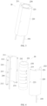
- the aerosol generating device can refer to FIG. 1 to FIG. 2 in structure, the overall shape of the device is roughly configured as a tabular tube, and external components of the aerosol generating device include:
- the upper cove 11 includes an opening 12, through which the smokable material A may be received, in the length direction of the shell 10, at least in part within the shell 10 to be heated, or through which the smokable material A may be removed from inside of the shell 10.
- the shell 10 is further provided with a switch button 13 on one side in a width direction, a user may manually actuate the switch button 13 to control the start or stop of the aerosol generating device.
- a heating mechanism 20 is provided within the shell 10; in the preferred embodiment shown in FIG. 2 , a heat insulating element 30, which is arranged on outside of the heating mechanism 20 in a radial direction, is further provided within the shell 10, to prevent the heat being transferred outward from the heating mechanism 20 to a surface of the shell 10.
- the heat insulating element 30 is a vacuum heat insulating tube having an internal vacuum area, and the like.
- the heating mechanism further includes an upper support element 40 and a lower support element 50, both of which are in the shape of a hollow ring and which provide support for two ends of the heating mechanism 20 and the heat insulating element 30 respectively, so that the heating mechanism 20 and the heat insulating element 30 are stably retained within the shell 10.
- the infrared emitter 230 is an electro-infrared emitter which can radiate infrared rays towards the smokable material A when supplied with power; specifically, the infrared emitter 230 includes:
- the infrared emitting coating 233 preferably is composed of an oxide of at least one metallic element among Mg, Al, Ti, Zr, Mn, Fe, Co, Ni, Cu, Cr, Zn, etc.; these metallic oxides when heated to an appropriate temperature can radiate far infrared rays having a heating effect; the thickness of the coating preferably may be controlled between 30 ⁇ m to 50 ⁇ m; the formation mode on the surface of the tubular base 231 may be achieved by spraying the oxides of the above metallic elements on the outer surface of the tubular base 231 through an atmospheric plasma spraying method and then curing it.
- the heating mechanism 20 includes a retaining mechanism arranged on outside of the infrared emitter 230 in a radial direction, so that on one hand the infrared emitter 230 may be stably retained within the shell 10 and on the other hand a conductive device may stably abut against or contact the surface of the infrared emitter 230 through the retaining mechanism; further, the conductive device may be connected to the battery cell 14, thereby supplying power to the infrared emitting coating 233 of the infrared emitter 230.
- the retaining mechanism includes a first retaining element 210 and a second retaining element 220 that are arranged in turn in a circumferential direction surrounding the infrared emitter 230; according to the preferred embodiment shown in FIG. 4 , the first retaining element 210 and the second retaining element 220 are in the shape of a semicircular tube, which after being cooperated and assembled can compose a complete circular tubular fixed structure surrounding the infrared emitter 230.
- the first retaining element 210 is provided with a first clamping protrusion 212 that is located at two ends of the length direction and a second clamping protrusion 213 that is located on the middle part; correspondingly, the second retaining element 220 defines a first clamping groove 222 adapted to the first clamping protrusion 212 and a second clamping groove 223 adapted to the second clamping protrusion 213; during the assembly process, the first clamping protrusion 212 is embedded into the first clamping protrusion 212, and the second clamping protrusion 213 is embedded into the second clamping groove 223, so that the first retaining element 210 is connected and fixed with the second retaining element 220.
- first retaining element 210 in the length direction are provided respectively with a first support part 211 and a second support part 214 that are extending inwards in a radial direction; similarly, two ends of the second retaining element 210 are further provided with a third support part 221 and a fourth support part (not shown in figures due to the angle of view) that are extending inwards in a radial direction; the above support parts are arranged for the purpose of providing support for two ends of the infrared emitter 230 accommodated within the first retaining element 210 and the second retaining element 220, thereby preventing the infrared emitter 230 moving in the axial direction and thus retaining and securing the infrared emitter 230.
- an inner wall of the first retaining element 210 is provided with a first conductive element 240; specifically, a main body of the first conductive element 240 is in the shape of a strip or sheet that extends in the length direction of the first retaining element 210, and the first conductive element 240, after being installed, extends at least in part to outside of a lower end of the first retaining element 210; similarly, an inner wall of the second retaining element 220 is also provided with a second conductive element 250.
- the first conductive element 240 and the second conductive element 250 are attached to and perform conduction with the infrared emitting coating 233 on the outer surface of the infrared emitter 230, so that subsequently positive and negative electrodes of the battery cell 14 may be connected to the first conductive element 240 and the second conductive element to supply power to the infrared emitting coating 233, thereby providing the infrared emitting coating 233 with a current in the circumferential direction, as indicated by the arrow r shown in FIG. 6 and FIG. 4 .
- extension lengths of the first conductive element 240 and the second conductive element 250 in the axial direction of the infrared emitter 230 are greater than the extension length of the infrared emitting coating 233, so that the circumferential current of the infrared emitting coating 233 is continuous and complete.
- the inner wall of the first retaining element 210 defines a groove 215 configured to fix the first conductive element 240.
- the first conductive element 240 further includes an extension part 241 extended out from the main body along two sides thereof, such that the first conductive element 240 after being accommodated or retained within the groove 215 is prevented from an axial movement.
- flexible materials capable of providing an elastic force such as silicone rubber, polyimide, sponge, etc., may be formed within the groove 215 by means of gluing, filling or spraying, etc., so that the first conductive element 240, when accommodated within the groove 215, can stably contact or be attached to the surface of the infrared emitting coating 233 under the action of the flexible force.
- the second conductive element 250 has the same shape, structure, fixing and installation method, and the technical personnel can understand and perform implementation with reference to the first conductive element 240.
- the first conductive element 240 and the second conductive element 250 may be made of materials with good conductivity and low resistivity, such as gold, silver, copper, etc.
- the inner wall of the first retaining element 210a defines a groove 215a close to upper and lower ends, a main body of the groove 215 extends in the circumferential direction, and correspondingly the first conductive element 240a shown in FIG. 8 is placed into the groove 215a in the circumferential direction.
- the above first conductive element 240a after being installed is attached to the outer surface of the infrared emitter 230 in the circumferential direction to form conduction. Note that the first conductive element 240a shown in FIG.
- the first conductive element 8 is in the shape of a straight strip; during implementation, due to the bendability and ductility of metal materials, the first conductive element may be conveniently installed into the groove 215a and attached to the outer surface of the infrared emitter 230 in the circumferential direction; alternatively, during other convenient implementations, the first conductive element 240a may be directly prepared into a ring shape, for example, the first conductive element 240b shown in FIG. 9 .
- the second conductive element 20 which is provided corresponding to the first conductive element 240a, is attached to the outer surface of the infrared emitter 230 in the circumferential direction on the other end; the first and second conductive elements serve as positive and negative electrodes respectively to supply power to the infrared emitter 230, forming a current in the axial direction rather than the radial direction indicated by the arrow r shown in FIG. 4 .
- first conductive element 240a further includes an extension part 241a extended out from the main body, which on one hand prevents the first conductive element 240a moving in the circumferential direction within the groove 215a and which after being installed can extend to outside of the first retaining element 210a to be subsequently connected to positive and negative electrodes of the battery cell 14.
Landscapes
- Resistance Heating (AREA)
- Nozzles (AREA)
Claims (12)
- Aerosolerzeugungsvorrichtung, die so konfiguriert ist, dass sie ein rauchbares Material erhitzt, um ein Aerosol zu erzeugen
zur Inhalation, umfassend eine Schale (10), wobei im Inneren der Schale (10) vorgesehen sind:eine Kammer (232), die zur Aufnahme eines rauchbaren Materials ausgelegt ist;einen Infrarotstrahler (230), der eine röhrenförmige Basis (231) umfasst, die sich in einer axialen Richtung der Kammer (232) erstreckt und die Kammer (232) umgibt, und eine infrarot-emittierende Beschichtung (233), die auf einer Außenfläche der röhrenförmigen Basis (231) ausgebildet ist;ein leitendes Element (240), das mit der infrarot-emittierenden Beschichtung (233) leitend verbunden ist;einen Haltemechanismus (210, 220), der so konfiguriert ist, dass er auf der Außenseite des Infrarotstrahlers (230) angeordnet ist, wobei das leitende Element (240) zwischen dem Haltemechanismus (210, 220) und dem Infrarotstrahler (230) in einer radialen Richtung des Infrarotstrahlers (230) angeordnet ist; undeine Batteriezelle (14), die elektrisch mit dem leitenden Element (240) verbunden ist um die infrarot-emittierende Beschichtung (233) mit Strom zu versorgen, so dass die infrarot-emittierende Beschichtung (233) Infrarotstrahlen in Richtung des in der Kammer (232) aufgenommenen rauchbaren Materials abstrahlt,wodurch das rauchbare Material erhitzt wird,dadurch gekennzeichnet, dass
der Haltemechanismus (210, 220) so konfiguriert ist, dass er eine Stütze für das leitende Element (240) bereitstellt, wobei das leitende Element (240) unter der Stütze des Haltemechanismus (210, 220) an der infrarot-emittierenden Beschichtung (233) anliegt. - Aerosolerzeugungsvorrichtung nach Anspruch 1, wobei sich das leitende Element (240) zumindest teilweise außerhalb des Haltemechanismus (210, 220) in einer axialen Richtung des Haltemechanismus (210, 220) erstreckt und ein elektrisches Verbindungsteil bildet, das so konfiguriert ist, dass es eine elektrische Verbindung mit der Batteriezelle (14) ausbildet.
- Aerosolerzeugungsvorrichtung nach Anspruch 2, wobei das leitende Element (240) umfasst:einen ersten Teil, der sich in einer axialen Richtung des Infrarotstrahlers (230) erstreckt und stößt an die infrarot-emittierende Beschichtung (233); undeinen zweiten Teil, der dadurch gebildet wird, dass er sich von dem ersten Teil in einer Umfangsrichtung des Infrarotstrahlers (230) erstreckt; wobeizumindest ein Teil des ersten Teils sich in der axialen Richtung des Haltemechanismus (210, 220) zur Außenseite des Haltemechanismus (210, 220) erstreckt, um den elektrischen Verbindungsteil zu bilden.
- Aerosolerzeugungsvorrichtung nach Anspruch 3, wobei eine Länge des ersten Teils,
das sich in der axialen Richtung des Infrarotstrahlers (230) erstreckt, größer ist als eine Länge der infrarotabstrahlenden Beschichtung (233), die sich in der axialen Richtung des Infrarotstrahlers (230) erstreckt. - Aerosolerzeugungsvorrichtung nach Anspruch 2, wobei das leitende Element (240) umfasst: einen ersten Teil, der sich in einer Umfangsrichtung um den Infrarotstrahler (230)herum erstreckt und an die infrarot-emittierende Beschichtung (233) stößt; undeinen zweiten Teil, der sich vom ersten Teil in axialer Richtung des Haltemechanismus (210, 220) erstreckt und sich zumindest teilweise bis zur Außenseite des Haltemechanismus (210, 220) erstreckt, um das elektrische Verbindungsteil zu bilden.
- Aerosolerzeugungsvorrichtung nach Anspruch 5, wobei der erste Teil die Form eines Rings hat, der den Infrarotstrahler (230) umgibt;
oder der erste Teil hat die Form eines Streifens, der in der Umfangsrichtung des Infrarotstrahlers (230) um eine Oberfläche des Infrarotstrahlers (230) gewickelt wird. - Aerosolerzeugungsvorrichtung nach einem der Ansprüche 1 bis 6, wobei eine Innenfläche des Haltemechanismus (210, 220) eine Aufnahmerille (215) definiert, in der das leitende Element (240) zumindest teilweise untergebracht ist und die hierdurch eine Unterstützung für das leitende Element (240) bietet.
- Aerosolerzeugungsvorrichtung nach einem der Ansprüche 1 bis 6, wobei der Haltemechanismus (210, 220) umfasst ein erstes Ende und ein zweites Ende, die sich in Längsrichtung gegenüberliegen;das erste Ende ist mit einem ersten Stützteil (211) versehen, das sich in radialer Richtung nach innen erstreckt, und das erste Stützteil (211) ist so konfiguriert, dass es den Infrarotstrahler (230) am ersten Ende trägt;und/oder das zweite Ende mit einem zweiten Stützteil (214) versehen ist, das sich in einer radialen Richtung nach innen erstreckt, und das zweite Stützteil (214) so konfiguriert ist, dass es den Infrarotstrahler (230) am zweiten Ende stützt.
- Aerosolerzeugungsvorrichtung nach einem der Ansprüche 1 bis 4, wobei der Haltemechanismus (210, 220) ein erstes Halteelement (210) und ein zweites Halteelement (220) umfasst, die abwechselnd in einer den Infrarotstrahler (230) umgebenden Umfangsrichtung angeordnet sind, und zwischen dem ersten Halteelement (210) und dem zweiten Halteelement (220) ein Halteraum gebildet ist; und der Infrarotstrahler (230) und das leitende Element (240) innerhalb des Halteraums gehalten werden.
- Aerosolerzeugungsvorrichtung nach Anspruch 9, wobei das erste Halteelement (210) mit einer sich in Umfangsrichtung erstreckenden ersten Verbindungsstruktur versehen ist;das zweite Halteelement (220) mit einer zweiten, sich in Umfangsrichtung erstreckenden Verbindungsstruktur versehen ist;das erste Halteelement (210) und das zweite Halteelement (220) durch die Zusammenarbeit zwischen der ersten Verbindungsstruktur und der zweiten Verbindungsstruktur verbunden sind.
- Aerosolerzeugungsvorrichtung nach Anspruch 9, wobei die Querschnitte sowohl des ersten Halteelements (210) als auch des zweiten Halteelements (220) die Form eines halbkreisförmigen Rings aufweisen.
- Aerosolerzeugungsvorrichtung nach Anspruch 9, wobei die Außenflächen des ersten Halteelements (210) und des zweiten Halteelements (220) flächig miteinander verbunden sind.
Applications Claiming Priority (2)
| Application Number | Priority Date | Filing Date | Title |
|---|---|---|---|
| CN202010016109.XA CN113080522A (zh) | 2020-01-08 | 2020-01-08 | 气雾生成装置 |
| PCT/CN2021/070919 WO2021139786A1 (zh) | 2020-01-08 | 2021-01-08 | 气雾生成装置 |
Publications (3)
| Publication Number | Publication Date |
|---|---|
| EP4088596A1 EP4088596A1 (de) | 2022-11-16 |
| EP4088596A4 EP4088596A4 (de) | 2023-08-23 |
| EP4088596B1 true EP4088596B1 (de) | 2023-12-13 |
Family
ID=76663352
Family Applications (1)
| Application Number | Title | Priority Date | Filing Date |
|---|---|---|---|
| EP21738216.7A Active EP4088596B1 (de) | 2020-01-08 | 2021-01-08 | Aerosolerzeugungsvorrichtung |
Country Status (6)
| Country | Link |
|---|---|
| US (1) | US12484622B2 (de) |
| EP (1) | EP4088596B1 (de) |
| JP (1) | JP7488341B2 (de) |
| KR (1) | KR102834827B1 (de) |
| CN (1) | CN113080522A (de) |
| WO (1) | WO2021139786A1 (de) |
Families Citing this family (5)
| Publication number | Priority date | Publication date | Assignee | Title |
|---|---|---|---|---|
| JP2023520552A (ja) * | 2020-04-06 | 2023-05-17 | ジェイティー インターナショナル エス.エイ. | エアロゾル発生デバイスのための断熱スリーブ |
| CN215958364U (zh) * | 2021-09-02 | 2022-03-08 | 深圳市合元科技有限公司 | 气溶胶生成装置 |
| CN114916715A (zh) * | 2022-05-18 | 2022-08-19 | 安徽中烟工业有限责任公司 | 用于产生气雾的红外加热装置及系统 |
| CN218605047U (zh) * | 2022-07-21 | 2023-03-14 | 深圳市合元科技有限公司 | 加热组件以及气溶胶生成装置 |
| PL4381969T3 (pl) * | 2022-12-06 | 2025-10-20 | Jt International Sa | Urządzenie do wytwarzania aerozolu za pomocą izolatora |
Family Cites Families (22)
| Publication number | Priority date | Publication date | Assignee | Title |
|---|---|---|---|---|
| SE8405479D0 (sv) * | 1984-11-01 | 1984-11-01 | Nilsson Sven Erik | Sett att administrera flyktiga, fysiologiskt, aktiva emnen och anordning for detta |
| US20080257367A1 (en) * | 2007-04-23 | 2008-10-23 | Greg Paterno | Electronic evaporable substance delivery device and method |
| EP2327318A1 (de) * | 2009-11-27 | 2011-06-01 | Philip Morris Products S.A. | Elektrisch erhitztes Rauchsystem mit interner oder externer Heizvorrichtung |
| CN201700020U (zh) * | 2010-05-13 | 2011-01-05 | 陈宗渊 | 电阻发热器改良结构 |
| US9999250B2 (en) * | 2010-05-15 | 2018-06-19 | Rai Strategic Holdings, Inc. | Vaporizer related systems, methods, and apparatus |
| US9462830B2 (en) * | 2011-07-12 | 2016-10-11 | Huizhou Kimree Technology Co., Ltd. | Electronic cigarette |
| EP3043663A4 (de) * | 2013-09-13 | 2017-05-10 | Nicodart Inc. | Programmierbare elektronische verdampfungsvorrichtung und raucherentwöhnung system |
| NZ718007A (en) * | 2013-10-29 | 2017-06-30 | British American Tobacco Investments Ltd | Apparatus for heating smokable material |
| US10159282B2 (en) * | 2013-12-23 | 2018-12-25 | Juul Labs, Inc. | Cartridge for use with a vaporizer device |
| CN205567812U (zh) * | 2014-06-20 | 2016-09-14 | 惠州市吉瑞科技有限公司 | 一种电子烟 |
| CN104397878B (zh) | 2014-11-21 | 2017-10-27 | 黄金珍 | 加热非燃烧型电子烟雾化器和电子烟 |
| CN205052881U (zh) * | 2015-09-29 | 2016-03-02 | 深圳市合元科技有限公司 | 卷烟烘焙装置 |
| CN205547365U (zh) * | 2016-04-08 | 2016-09-07 | 深圳市博迪科技开发有限公司 | 带有玻璃发热体的烧烟草式发热组件及电子烟 |
| CN207236078U (zh) | 2016-09-06 | 2018-04-17 | 深圳市合元科技有限公司 | 烟雾发生装置 |
| CN106490686B (zh) | 2016-11-23 | 2024-06-18 | 深圳市合元科技有限公司 | 烟雾生成器、电子烟及可拆卸安装的雾化装置 |
| KR101989855B1 (ko) * | 2017-04-18 | 2019-06-17 | 주식회사 아모센스 | 궐련형 전자담배장치용 발열히터 |
| KR102116961B1 (ko) * | 2017-07-21 | 2020-06-02 | 주식회사 아모센스 | 궐련형 전자담배용 히터조립체 및 이를 포함하는 궐련형 전자담배 |
| CN108095203A (zh) | 2018-02-09 | 2018-06-01 | 昆明纳太科技有限公司 | 一种电加热不燃烧卷烟用辐射式加热装置 |
| CN108185537B (zh) | 2018-02-26 | 2020-11-20 | 冷朝阳 | 一种气溶胶生成装置及气溶胶生成制品 |
| CN209931486U (zh) * | 2019-02-28 | 2020-01-14 | 深圳市合元科技有限公司 | 低温烘烤烟具 |
| CN110384264A (zh) * | 2019-07-15 | 2019-10-29 | 深圳市合元科技有限公司 | 加热器及低温加热烟具 |
| CN212279891U (zh) * | 2019-12-23 | 2021-01-05 | 深圳市合元科技有限公司 | 加热器以及包括该加热器的烟具 |
-
2020
- 2020-01-08 CN CN202010016109.XA patent/CN113080522A/zh active Pending
-
2021
- 2021-01-08 US US17/758,464 patent/US12484622B2/en active Active
- 2021-01-08 EP EP21738216.7A patent/EP4088596B1/de active Active
- 2021-01-08 KR KR1020227027318A patent/KR102834827B1/ko active Active
- 2021-01-08 WO PCT/CN2021/070919 patent/WO2021139786A1/zh not_active Ceased
- 2021-01-08 JP JP2022541992A patent/JP7488341B2/ja active Active
Also Published As
| Publication number | Publication date |
|---|---|
| KR20220124774A (ko) | 2022-09-14 |
| EP4088596A4 (de) | 2023-08-23 |
| WO2021139786A1 (zh) | 2021-07-15 |
| US20230337738A1 (en) | 2023-10-26 |
| JP7488341B2 (ja) | 2024-05-21 |
| JP2023509192A (ja) | 2023-03-07 |
| CN113080522A (zh) | 2021-07-09 |
| EP4088596A1 (de) | 2022-11-16 |
| US12484622B2 (en) | 2025-12-02 |
| KR102834827B1 (ko) | 2025-07-15 |
Similar Documents
| Publication | Publication Date | Title |
|---|---|---|
| EP4088596B1 (de) | Aerosolerzeugungsvorrichtung | |
| JP6801139B2 (ja) | エアロゾル生成装置、その制御方法、及びそれを含む充電システム | |
| CN211910542U (zh) | 气雾生成装置及用于气雾生成装置的加热机构 | |
| CN211910545U (zh) | 气雾生成装置及用于气雾生成装置的红外发射器 | |
| KR102858625B1 (ko) | 에어로졸 생성 장치 및 적외선 방사기 | |
| US12349729B2 (en) | Aerosol-generating device and infrared emitter | |
| CN221962870U (zh) | 气溶胶生成装置 | |
| CN223067947U (zh) | 气雾生成装置及用于气雾生成装置的加热器 | |
| CN223310684U (zh) | 气雾生成装置及用于气雾生成装置的加热机构 | |
| CN222941805U (zh) | 气雾生成装置及用于气雾生成装置的加热器 | |
| JP2026510468A (ja) | エアロゾル供給デバイス用ヒータ | |
| EP4611575A1 (de) | Aerosolbereitstellungsvorrichtung | |
| KR20250121567A (ko) | 히터 및 이의 제조방법, 에어로졸 생성장치 | |
| EP4611571A1 (de) | Aerosolbereitstellungsvorrichtung | |
| CN118303670A (zh) | 气雾生成装置及用于气雾生成装置的加热器 | |
| CN121587471A (zh) | 气雾生成装置及用于气雾生成装置的加热机构 | |
| WO2024060982A1 (zh) | 加热组件以及气溶胶生成装置 | |
| EP4613053A1 (de) | Heizgerät für eine aerosolbereitstellungsvorrichtung | |
| WO2024094643A1 (en) | Heater for an aerosol provision device | |
| CN116473297A (zh) | 气雾生成装置及用于气雾生成装置的加热器 | |
| CN121312894A (zh) | 气雾生成装置及用于气雾生成装置的加热器 |
Legal Events
| Date | Code | Title | Description |
|---|---|---|---|
| STAA | Information on the status of an ep patent application or granted ep patent |
Free format text: STATUS: THE INTERNATIONAL PUBLICATION HAS BEEN MADE |
|
| PUAI | Public reference made under article 153(3) epc to a published international application that has entered the european phase |
Free format text: ORIGINAL CODE: 0009012 |
|
| STAA | Information on the status of an ep patent application or granted ep patent |
Free format text: STATUS: REQUEST FOR EXAMINATION WAS MADE |
|
| 17P | Request for examination filed |
Effective date: 20220715 |
|
| AK | Designated contracting states |
Kind code of ref document: A1 Designated state(s): AL AT BE BG CH CY CZ DE DK EE ES FI FR GB GR HR HU IE IS IT LI LT LU LV MC MK MT NL NO PL PT RO RS SE SI SK SM TR |
|
| A4 | Supplementary search report drawn up and despatched |
Effective date: 20230720 |
|
| RIC1 | Information provided on ipc code assigned before grant |
Ipc: A24F 40/20 20200101ALN20230714BHEP Ipc: H05B 3/46 20060101ALI20230714BHEP Ipc: H05B 3/06 20060101ALI20230714BHEP Ipc: A24F 40/46 20200101AFI20230714BHEP |
|
| GRAP | Despatch of communication of intention to grant a patent |
Free format text: ORIGINAL CODE: EPIDOSNIGR1 |
|
| STAA | Information on the status of an ep patent application or granted ep patent |
Free format text: STATUS: GRANT OF PATENT IS INTENDED |
|
| RIC1 | Information provided on ipc code assigned before grant |
Ipc: A24F 40/20 20200101ALN20230905BHEP Ipc: H05B 3/46 20060101ALI20230905BHEP Ipc: H05B 3/06 20060101ALI20230905BHEP Ipc: A24F 40/46 20200101AFI20230905BHEP |
|
| INTG | Intention to grant announced |
Effective date: 20230919 |
|
| GRAS | Grant fee paid |
Free format text: ORIGINAL CODE: EPIDOSNIGR3 |
|
| GRAA | (expected) grant |
Free format text: ORIGINAL CODE: 0009210 |
|
| STAA | Information on the status of an ep patent application or granted ep patent |
Free format text: STATUS: THE PATENT HAS BEEN GRANTED |
|
| AK | Designated contracting states |
Kind code of ref document: B1 Designated state(s): AL AT BE BG CH CY CZ DE DK EE ES FI FR GB GR HR HU IE IS IT LI LT LU LV MC MK MT NL NO PL PT RO RS SE SI SK SM TR |
|
| REG | Reference to a national code |
Ref country code: GB Ref legal event code: FG4D |
|
| REG | Reference to a national code |
Ref country code: CH Ref legal event code: EP |
|
| REG | Reference to a national code |
Ref country code: IE Ref legal event code: FG4D |
|
| REG | Reference to a national code |
Ref country code: DE Ref legal event code: R096 Ref document number: 602021007728 Country of ref document: DE |
|
| PG25 | Lapsed in a contracting state [announced via postgrant information from national office to epo] |
Ref country code: GR Free format text: LAPSE BECAUSE OF FAILURE TO SUBMIT A TRANSLATION OF THE DESCRIPTION OR TO PAY THE FEE WITHIN THE PRESCRIBED TIME-LIMIT Effective date: 20240314 |
|
| REG | Reference to a national code |
Ref country code: LT Ref legal event code: MG9D |
|
| PG25 | Lapsed in a contracting state [announced via postgrant information from national office to epo] |
Ref country code: LT Free format text: LAPSE BECAUSE OF FAILURE TO SUBMIT A TRANSLATION OF THE DESCRIPTION OR TO PAY THE FEE WITHIN THE PRESCRIBED TIME-LIMIT Effective date: 20231213 |
|
| REG | Reference to a national code |
Ref country code: NL Ref legal event code: MP Effective date: 20231213 |
|
| PG25 | Lapsed in a contracting state [announced via postgrant information from national office to epo] |
Ref country code: ES Free format text: LAPSE BECAUSE OF FAILURE TO SUBMIT A TRANSLATION OF THE DESCRIPTION OR TO PAY THE FEE WITHIN THE PRESCRIBED TIME-LIMIT Effective date: 20231213 |
|
| PG25 | Lapsed in a contracting state [announced via postgrant information from national office to epo] |
Ref country code: LT Free format text: LAPSE BECAUSE OF FAILURE TO SUBMIT A TRANSLATION OF THE DESCRIPTION OR TO PAY THE FEE WITHIN THE PRESCRIBED TIME-LIMIT Effective date: 20231213 Ref country code: GR Free format text: LAPSE BECAUSE OF FAILURE TO SUBMIT A TRANSLATION OF THE DESCRIPTION OR TO PAY THE FEE WITHIN THE PRESCRIBED TIME-LIMIT Effective date: 20240314 Ref country code: ES Free format text: LAPSE BECAUSE OF FAILURE TO SUBMIT A TRANSLATION OF THE DESCRIPTION OR TO PAY THE FEE WITHIN THE PRESCRIBED TIME-LIMIT Effective date: 20231213 Ref country code: BG Free format text: LAPSE BECAUSE OF FAILURE TO SUBMIT A TRANSLATION OF THE DESCRIPTION OR TO PAY THE FEE WITHIN THE PRESCRIBED TIME-LIMIT Effective date: 20240313 |
|
| REG | Reference to a national code |
Ref country code: AT Ref legal event code: MK05 Ref document number: 1639665 Country of ref document: AT Kind code of ref document: T Effective date: 20231213 |
|
| PG25 | Lapsed in a contracting state [announced via postgrant information from national office to epo] |
Ref country code: NL Free format text: LAPSE BECAUSE OF FAILURE TO SUBMIT A TRANSLATION OF THE DESCRIPTION OR TO PAY THE FEE WITHIN THE PRESCRIBED TIME-LIMIT Effective date: 20231213 |
|
| P01 | Opt-out of the competence of the unified patent court (upc) registered |
Effective date: 20240423 |
|
| PG25 | Lapsed in a contracting state [announced via postgrant information from national office to epo] |
Ref country code: SE Free format text: LAPSE BECAUSE OF FAILURE TO SUBMIT A TRANSLATION OF THE DESCRIPTION OR TO PAY THE FEE WITHIN THE PRESCRIBED TIME-LIMIT Effective date: 20231213 Ref country code: RS Free format text: LAPSE BECAUSE OF FAILURE TO SUBMIT A TRANSLATION OF THE DESCRIPTION OR TO PAY THE FEE WITHIN THE PRESCRIBED TIME-LIMIT Effective date: 20231213 Ref country code: NO Free format text: LAPSE BECAUSE OF FAILURE TO SUBMIT A TRANSLATION OF THE DESCRIPTION OR TO PAY THE FEE WITHIN THE PRESCRIBED TIME-LIMIT Effective date: 20240313 Ref country code: NL Free format text: LAPSE BECAUSE OF FAILURE TO SUBMIT A TRANSLATION OF THE DESCRIPTION OR TO PAY THE FEE WITHIN THE PRESCRIBED TIME-LIMIT Effective date: 20231213 Ref country code: LV Free format text: LAPSE BECAUSE OF FAILURE TO SUBMIT A TRANSLATION OF THE DESCRIPTION OR TO PAY THE FEE WITHIN THE PRESCRIBED TIME-LIMIT Effective date: 20231213 Ref country code: HR Free format text: LAPSE BECAUSE OF FAILURE TO SUBMIT A TRANSLATION OF THE DESCRIPTION OR TO PAY THE FEE WITHIN THE PRESCRIBED TIME-LIMIT Effective date: 20231213 |
|
| PG25 | Lapsed in a contracting state [announced via postgrant information from national office to epo] |
Ref country code: IS Free format text: LAPSE BECAUSE OF FAILURE TO SUBMIT A TRANSLATION OF THE DESCRIPTION OR TO PAY THE FEE WITHIN THE PRESCRIBED TIME-LIMIT Effective date: 20240413 |
|
| PG25 | Lapsed in a contracting state [announced via postgrant information from national office to epo] |
Ref country code: CZ Free format text: LAPSE BECAUSE OF FAILURE TO SUBMIT A TRANSLATION OF THE DESCRIPTION OR TO PAY THE FEE WITHIN THE PRESCRIBED TIME-LIMIT Effective date: 20231213 Ref country code: AT Free format text: LAPSE BECAUSE OF FAILURE TO SUBMIT A TRANSLATION OF THE DESCRIPTION OR TO PAY THE FEE WITHIN THE PRESCRIBED TIME-LIMIT Effective date: 20231213 |
|
| PG25 | Lapsed in a contracting state [announced via postgrant information from national office to epo] |
Ref country code: SK Free format text: LAPSE BECAUSE OF FAILURE TO SUBMIT A TRANSLATION OF THE DESCRIPTION OR TO PAY THE FEE WITHIN THE PRESCRIBED TIME-LIMIT Effective date: 20231213 |
|
| PG25 | Lapsed in a contracting state [announced via postgrant information from national office to epo] |
Ref country code: SM Free format text: LAPSE BECAUSE OF FAILURE TO SUBMIT A TRANSLATION OF THE DESCRIPTION OR TO PAY THE FEE WITHIN THE PRESCRIBED TIME-LIMIT Effective date: 20231213 Ref country code: SK Free format text: LAPSE BECAUSE OF FAILURE TO SUBMIT A TRANSLATION OF THE DESCRIPTION OR TO PAY THE FEE WITHIN THE PRESCRIBED TIME-LIMIT Effective date: 20231213 Ref country code: RO Free format text: LAPSE BECAUSE OF FAILURE TO SUBMIT A TRANSLATION OF THE DESCRIPTION OR TO PAY THE FEE WITHIN THE PRESCRIBED TIME-LIMIT Effective date: 20231213 Ref country code: IT Free format text: LAPSE BECAUSE OF FAILURE TO SUBMIT A TRANSLATION OF THE DESCRIPTION OR TO PAY THE FEE WITHIN THE PRESCRIBED TIME-LIMIT Effective date: 20231213 Ref country code: IS Free format text: LAPSE BECAUSE OF FAILURE TO SUBMIT A TRANSLATION OF THE DESCRIPTION OR TO PAY THE FEE WITHIN THE PRESCRIBED TIME-LIMIT Effective date: 20240413 Ref country code: EE Free format text: LAPSE BECAUSE OF FAILURE TO SUBMIT A TRANSLATION OF THE DESCRIPTION OR TO PAY THE FEE WITHIN THE PRESCRIBED TIME-LIMIT Effective date: 20231213 Ref country code: CZ Free format text: LAPSE BECAUSE OF FAILURE TO SUBMIT A TRANSLATION OF THE DESCRIPTION OR TO PAY THE FEE WITHIN THE PRESCRIBED TIME-LIMIT Effective date: 20231213 Ref country code: AT Free format text: LAPSE BECAUSE OF FAILURE TO SUBMIT A TRANSLATION OF THE DESCRIPTION OR TO PAY THE FEE WITHIN THE PRESCRIBED TIME-LIMIT Effective date: 20231213 |
|
| PG25 | Lapsed in a contracting state [announced via postgrant information from national office to epo] |
Ref country code: PL Free format text: LAPSE BECAUSE OF FAILURE TO SUBMIT A TRANSLATION OF THE DESCRIPTION OR TO PAY THE FEE WITHIN THE PRESCRIBED TIME-LIMIT Effective date: 20231213 Ref country code: PT Free format text: LAPSE BECAUSE OF FAILURE TO SUBMIT A TRANSLATION OF THE DESCRIPTION OR TO PAY THE FEE WITHIN THE PRESCRIBED TIME-LIMIT Effective date: 20240415 |
|
| PG25 | Lapsed in a contracting state [announced via postgrant information from national office to epo] |
Ref country code: PT Free format text: LAPSE BECAUSE OF FAILURE TO SUBMIT A TRANSLATION OF THE DESCRIPTION OR TO PAY THE FEE WITHIN THE PRESCRIBED TIME-LIMIT Effective date: 20240415 Ref country code: PL Free format text: LAPSE BECAUSE OF FAILURE TO SUBMIT A TRANSLATION OF THE DESCRIPTION OR TO PAY THE FEE WITHIN THE PRESCRIBED TIME-LIMIT Effective date: 20231213 |
|
| REG | Reference to a national code |
Ref country code: CH Ref legal event code: PL |
|
| PG25 | Lapsed in a contracting state [announced via postgrant information from national office to epo] |
Ref country code: LU Free format text: LAPSE BECAUSE OF NON-PAYMENT OF DUE FEES Effective date: 20240108 |
|
| REG | Reference to a national code |
Ref country code: DE Ref legal event code: R097 Ref document number: 602021007728 Country of ref document: DE |
|
| PG25 | Lapsed in a contracting state [announced via postgrant information from national office to epo] |
Ref country code: LU Free format text: LAPSE BECAUSE OF NON-PAYMENT OF DUE FEES Effective date: 20240108 Ref country code: MC Free format text: LAPSE BECAUSE OF FAILURE TO SUBMIT A TRANSLATION OF THE DESCRIPTION OR TO PAY THE FEE WITHIN THE PRESCRIBED TIME-LIMIT Effective date: 20231213 |
|
| PG25 | Lapsed in a contracting state [announced via postgrant information from national office to epo] |
Ref country code: DK Free format text: LAPSE BECAUSE OF FAILURE TO SUBMIT A TRANSLATION OF THE DESCRIPTION OR TO PAY THE FEE WITHIN THE PRESCRIBED TIME-LIMIT Effective date: 20231213 |
|
| PG25 | Lapsed in a contracting state [announced via postgrant information from national office to epo] |
Ref country code: BE Free format text: LAPSE BECAUSE OF NON-PAYMENT OF DUE FEES Effective date: 20240131 |
|
| PLBE | No opposition filed within time limit |
Free format text: ORIGINAL CODE: 0009261 |
|
| STAA | Information on the status of an ep patent application or granted ep patent |
Free format text: STATUS: NO OPPOSITION FILED WITHIN TIME LIMIT |
|
| PG25 | Lapsed in a contracting state [announced via postgrant information from national office to epo] |
Ref country code: CH Free format text: LAPSE BECAUSE OF NON-PAYMENT OF DUE FEES Effective date: 20240131 |
|
| PG25 | Lapsed in a contracting state [announced via postgrant information from national office to epo] |
Ref country code: SI Free format text: LAPSE BECAUSE OF FAILURE TO SUBMIT A TRANSLATION OF THE DESCRIPTION OR TO PAY THE FEE WITHIN THE PRESCRIBED TIME-LIMIT Effective date: 20231213 |
|
| PG25 | Lapsed in a contracting state [announced via postgrant information from national office to epo] |
Ref country code: SI Free format text: LAPSE BECAUSE OF FAILURE TO SUBMIT A TRANSLATION OF THE DESCRIPTION OR TO PAY THE FEE WITHIN THE PRESCRIBED TIME-LIMIT Effective date: 20231213 Ref country code: DK Free format text: LAPSE BECAUSE OF FAILURE TO SUBMIT A TRANSLATION OF THE DESCRIPTION OR TO PAY THE FEE WITHIN THE PRESCRIBED TIME-LIMIT Effective date: 20231213 Ref country code: CH Free format text: LAPSE BECAUSE OF NON-PAYMENT OF DUE FEES Effective date: 20240131 Ref country code: BE Free format text: LAPSE BECAUSE OF NON-PAYMENT OF DUE FEES Effective date: 20240131 |
|
| REG | Reference to a national code |
Ref country code: BE Ref legal event code: MM Effective date: 20240131 |
|
| 26N | No opposition filed |
Effective date: 20240916 |
|
| PG25 | Lapsed in a contracting state [announced via postgrant information from national office to epo] |
Ref country code: IE Free format text: LAPSE BECAUSE OF NON-PAYMENT OF DUE FEES Effective date: 20240108 |
|
| PG25 | Lapsed in a contracting state [announced via postgrant information from national office to epo] |
Ref country code: IE Free format text: LAPSE BECAUSE OF NON-PAYMENT OF DUE FEES Effective date: 20240108 |
|
| PG25 | Lapsed in a contracting state [announced via postgrant information from national office to epo] |
Ref country code: CY Free format text: LAPSE BECAUSE OF FAILURE TO SUBMIT A TRANSLATION OF THE DESCRIPTION OR TO PAY THE FEE WITHIN THE PRESCRIBED TIME-LIMIT; INVALID AB INITIO Effective date: 20210108 |
|
| PG25 | Lapsed in a contracting state [announced via postgrant information from national office to epo] |
Ref country code: HU Free format text: LAPSE BECAUSE OF FAILURE TO SUBMIT A TRANSLATION OF THE DESCRIPTION OR TO PAY THE FEE WITHIN THE PRESCRIBED TIME-LIMIT; INVALID AB INITIO Effective date: 20210108 |
|
| PG25 | Lapsed in a contracting state [announced via postgrant information from national office to epo] |
Ref country code: FI Free format text: LAPSE BECAUSE OF FAILURE TO SUBMIT A TRANSLATION OF THE DESCRIPTION OR TO PAY THE FEE WITHIN THE PRESCRIBED TIME-LIMIT Effective date: 20231213 |
|
| PG25 | Lapsed in a contracting state [announced via postgrant information from national office to epo] |
Ref country code: TR Free format text: LAPSE BECAUSE OF FAILURE TO SUBMIT A TRANSLATION OF THE DESCRIPTION OR TO PAY THE FEE WITHIN THE PRESCRIBED TIME-LIMIT Effective date: 20231213 |
|
| PGFP | Annual fee paid to national office [announced via postgrant information from national office to epo] |
Ref country code: GB Payment date: 20260127 Year of fee payment: 6 |
|
| PGFP | Annual fee paid to national office [announced via postgrant information from national office to epo] |
Ref country code: DE Payment date: 20260114 Year of fee payment: 6 |
|
| PGFP | Annual fee paid to national office [announced via postgrant information from national office to epo] |
Ref country code: FR Payment date: 20260128 Year of fee payment: 6 |