EP4088562A1 - Schneckenförderer und presse - Google Patents
Schneckenförderer und presse Download PDFInfo
- Publication number
- EP4088562A1 EP4088562A1 EP22172211.9A EP22172211A EP4088562A1 EP 4088562 A1 EP4088562 A1 EP 4088562A1 EP 22172211 A EP22172211 A EP 22172211A EP 4088562 A1 EP4088562 A1 EP 4088562A1
- Authority
- EP
- European Patent Office
- Prior art keywords
- screw conveyor
- press
- roller
- screw
- pressing
- Prior art date
- Legal status (The legal status is an assumption and is not a legal conclusion. Google has not performed a legal analysis and makes no representation as to the accuracy of the status listed.)
- Granted
Links
Images


Classifications
-
- A—HUMAN NECESSITIES
- A01—AGRICULTURE; FORESTRY; ANIMAL HUSBANDRY; HUNTING; TRAPPING; FISHING
- A01F—PROCESSING OF HARVESTED PRODUCE; HAY OR STRAW PRESSES; DEVICES FOR STORING AGRICULTURAL OR HORTICULTURAL PRODUCE
- A01F15/00—Baling presses for straw, hay or the like
- A01F15/08—Details
-
- A—HUMAN NECESSITIES
- A01—AGRICULTURE; FORESTRY; ANIMAL HUSBANDRY; HUNTING; TRAPPING; FISHING
- A01F—PROCESSING OF HARVESTED PRODUCE; HAY OR STRAW PRESSES; DEVICES FOR STORING AGRICULTURAL OR HORTICULTURAL PRODUCE
- A01F15/00—Baling presses for straw, hay or the like
- A01F15/08—Details
- A01F15/0825—Regulating or controlling density or shape of the bale
- A01F15/0833—Regulating or controlling density or shape of the bale for round balers
-
- A—HUMAN NECESSITIES
- A01—AGRICULTURE; FORESTRY; ANIMAL HUSBANDRY; HUNTING; TRAPPING; FISHING
- A01F—PROCESSING OF HARVESTED PRODUCE; HAY OR STRAW PRESSES; DEVICES FOR STORING AGRICULTURAL OR HORTICULTURAL PRODUCE
- A01F15/00—Baling presses for straw, hay or the like
- A01F15/07—Rotobalers, i.e. machines for forming cylindrical bales by winding and pressing
-
- B—PERFORMING OPERATIONS; TRANSPORTING
- B65—CONVEYING; PACKING; STORING; HANDLING THIN OR FILAMENTARY MATERIAL
- B65G—TRANSPORT OR STORAGE DEVICES, e.g. CONVEYORS FOR LOADING OR TIPPING, SHOP CONVEYOR SYSTEMS OR PNEUMATIC TUBE CONVEYORS
- B65G33/00—Screw or rotary spiral conveyors
- B65G33/24—Details
- B65G33/26—Screws
- B65G33/30—Screws with a discontinuous helical surface
-
- A—HUMAN NECESSITIES
- A01—AGRICULTURE; FORESTRY; ANIMAL HUSBANDRY; HUNTING; TRAPPING; FISHING
- A01D—HARVESTING; MOWING
- A01D61/00—Elevators or conveyors for binders or combines
- A01D61/002—Elevators or conveyors for binders or combines transversal conveying devices
-
- A—HUMAN NECESSITIES
- A01—AGRICULTURE; FORESTRY; ANIMAL HUSBANDRY; HUNTING; TRAPPING; FISHING
- A01F—PROCESSING OF HARVESTED PRODUCE; HAY OR STRAW PRESSES; DEVICES FOR STORING AGRICULTURAL OR HORTICULTURAL PRODUCE
- A01F15/00—Baling presses for straw, hay or the like
- A01F15/07—Rotobalers, i.e. machines for forming cylindrical bales by winding and pressing
- A01F2015/077—Pressing chamber formed by belts and rollers
-
- A—HUMAN NECESSITIES
- A01—AGRICULTURE; FORESTRY; ANIMAL HUSBANDRY; HUNTING; TRAPPING; FISHING
- A01F—PROCESSING OF HARVESTED PRODUCE; HAY OR STRAW PRESSES; DEVICES FOR STORING AGRICULTURAL OR HORTICULTURAL PRODUCE
- A01F15/00—Baling presses for straw, hay or the like
- A01F15/08—Details
- A01F15/18—Endless belts, rolls or the like
- A01F2015/186—Constructional details of rollers or the bearings of the rollers of the press chamber
Definitions
- the present invention relates to a screw conveyor for a press, in particular an agricultural baling press, with at least one roller on the peripheral surface of which screw helixes are provided at least in some areas to wrap around the roller in opposite directions in order to convey material, and a press, in particular an agricultural baling press with at least one roller, a flexible pressing means wrapped around the roller and at least one screw conveyor.
- Screw conveyors are known. They are used, for example, on presses to convey material, especially loose material. If a screw conveyor is used on an agricultural press, the loose material is usually harvested material, for example hay, straw or silage. If the press is an industrial press, it can be used, for example, to press paper, cardboard, waste or textiles.
- Screw conveyors of this type usually extend across the width of a pressing chamber of the press and are designed as a roller, on the surface of which two screw helixes are arranged which convey in opposite directions.
- the worm conveyor is set in rotation, so that the worm spirals take the loose material with them in order to bring it into a predetermined area of the pressing chamber. This is usually an edge area or a central area of the pressing chamber.
- There the good or material is then fed, if necessary again, to the material flow to be pressed.
- the DE-A1-4113311 a screw conveyor provided in close proximity to a roller, scraping off material accumulating on the roller and feeding it to a discharge point.
- a screw conveyor for a press has at least one roller, on the peripheral surface of which screw helixes are provided, at least in regions, looping around the roller in opposite directions in order to convey material.
- the screw flights are designed in such a way that they bring the material together in two collection areas located outside a central area of the screw conveyor, which improves the conveying of the material and thus prevents excessive loading of a pressing means in a central area of the screw conveyor and possibly increased wear.
- the press can in particular be an agricultural press, for example a press for forming round-cylindrical bales.
- the material to be pressed is in particular hay, straw or silage.
- the press it is also conceivable for the press to be designed as an industrial press, such as is used, for example, to form bales from waste, paper or textiles.
- the collection areas are provided at least essentially adjacent to the central area. If one of the screw flights ends in one of the collection areas, it conveys the material it carries into this collection area, where it is brought together with the material conveyed by the other screw flight.
- a particularly simple structure and/or a particularly uniform conveyance of the material results if the screw conveyor and/or the screw helix is/are designed symmetrically, in particular symmetrically, to a central axis of the screw conveyor, which is preferably aligned perpendicular to an axis of rotation of the screw conveyor.
- a press with at least one roller and a flexible pressing means wrapping around the at least one roller has a screw conveyor as described above.
- material that accumulates on one side of the pressing means for example, can be brought together in two collection areas and from there fed into a material flow or be fed to a pressing process without overloading and/or increased wear of the press or the pressing means.
- the press is in particular an agricultural baling press for forming round-cylindrical bales, in particular from crops such as hay, straw or silage.
- Such a press can be pulled by another vehicle or can also be self-propelled.
- such a press can also be used in the industrial sector, for example to form bales of paper, waste, fabric or other materials.
- the press has a variable pressing chamber, this can be formed in particular in some areas by the pressing means.
- the pressing means has an inside facing the pressing chamber and an outside facing away from the pressing chamber.
- the screw conveyor is preferably arranged on the outside of the pressing means, so that it brings together goods or material that accumulates on/on the outside in the two collecting areas.
- the pressing means can be designed in one piece. However, it is particularly favorable if the pressing means has a plurality of, but in particular three, pressing belts, with a gap preferably being provided between at least two of the pressing belts. If at least one of these gaps correlates at least essentially with one of the collection areas of the screw conveyor, the material in the collection area can pass through the gap from one side of the pressing means to its other side or to an inlet of the press, from where it is preferably Press room or a pressing process can be supplied.
- the screw conveyor is provided at least essentially adjacent to one roller, it can interact with it, for example in such a way that it prevents material/goods from accumulating/adhering to the roller or takes along material adhering to the roller and/or away from this one. If the at least one roller or the screw conveyor is arranged above an inlet into the pressing chamber, material/goods conveyed by the screw conveyor and/or removed from the roller can enter the pressing chamber via the inlet and be fed to a pressing process.
- the screw conveyor protrudes into the pressing chamber only in certain areas, for example only in an edge area.
- a particularly uniform conveyance results when the screw conveyor extends at least essentially over the width of the pressing chamber.
- the screw conveyor and/or the roller can be provided here or alternatively with respect to the press as such or a frame of the press.
- the roller and/or the screw conveyor are provided so that they can be driven. It is particularly favorable if the worm conveyor can be driven in such a way that the material to be conveyed is conveyed through the worm helix in the direction of the central area. In suitable applications, however, conveyance in the direction of the end regions of the screw conveyor is also conceivable as an alternative.
- the drawing shows an embodiment of a press 10 which has a frame 14 which carries a housing 12 and is supported on the base 18 via a chassis 16 .
- the press 10 shown is designed in the manner of a round baler and can be used both in the agricultural and in the industrial sector to produce a round bale, in particular a round cylindrical bale, from harvested crops, but also from waste, paper, fabric or tissue, cotton, tobacco etc. are used.
- Such a press 10 can be pulled by a work vehicle (not shown), preferably in the form of a farm tractor, or it can also be designed to be self-propelled.
- a drawbar 20 is provided at the front of the frame 14 in order to be able to attach the baler 10 to a farm tractor, not shown, and to be able to pull it over a field.
- a pick-up device 22 in the form of a pick-up is used to pick up crops lying on the ground 18, for example hay or straw deposited in a windrow.
- the harvested crop picked up by the pick-up device 22 is fed via an inlet 24 to a baling chamber 26 and is rolled up there spirally into a round-cylindrical bale, bound and then deposited on the ground 18 .
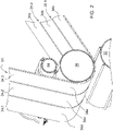
- the pressing chamber 26 is also formed by an endless pressing means 34 which, according to the present embodiment, is in the form of three adjacent pressing belts 34.1, 34.2, 34.3 (see figure 2 of the drawing) and is guided around a stationary roller 36 and a plurality of stationary and movable rollers 38, 40, 42, 44, 46, 48, 50, 52, 54, 56.
- the pressing means 34 has an inner side 34a facing the pressing chamber 26 and an outer side 34b.
- Two press belts 34.1, 34.2, 34.3 each define a gap 35.1, 35.2 between them.
- a screw conveyor 58 is provided adjacent to the stationary roller 36 on the outside 34b of the pressing means 34, which will be discussed in more detail below.
- the pressing chamber 26 is essentially surrounded on the peripheral side by the pressing means 34 and the rollers 28, 30 and 32, it is delimited laterally by side walls (not shown).
- the pressing means 34 assumes an initial state in which it straightly bridges the inlet 24 and a final state in which it wraps around a bale, not shown, like a large loop.
- the pressing chamber 26 is thus variable in its size, i. H. its diameter increases with the size of the bale.
- the bale is in the baling chamber 26 and is largely wrapped around by the pressing means 34, but falls backwards out of the baling chamber 26 onto the ground 18 as soon as the bale formation process is complete and an ejection flap 60 of the baler 10, which can be pivoted counterclockwise, opens.
- the screw conveyor 58 which is provided adjacent to the roller 36, outside the pressing space 26 defined by the pressing means 34, is shown in more detail.
- the screw conveyor 58 comprises a cylindrical hollow body or roller 62 having a peripheral surface 64, first and second edge regions 66a,b, a central region 68 and end faces 70a,b.
- the end faces 70a, b of the roller 62 adjoin end regions 72, which are designed in such a way that they can be rotatably accommodated in bearings (not shown) on the frame 14 of the baling press 10.
- the screw conveyor 58 can be set in rotation during operation by means of a drive (not shown).
- a first and a second helix 74a, b are provided on the peripheral surface 64 of the roller 62 and wrap around the roller 62 starting from the end faces 70a, b in the direction of the central region 68.
- the worm helices 74a, b wrap around the roller 62 in opposite directions, that is, the first worm helix 74a wraps around the roller 62 viewed from the end face 70a against the, the second worm helix 74b from the end face 70b viewed clockwise.
- Both helices 74a, b extend beyond a central axis M of the roller 62, so that they overlap in the central area 68 and end or run out in a collecting area 69 adjoining the central area 68.
- These collecting areas 69 are arranged in such a way that they correlate with gaps 35.1, 35.2 between the individual press belts 34.1, 34.2, 34.3.
- the screw conveyor 58 is set in rotation by the drive (not shown) in such a way that material located on the outside 34b outside of the pressing chamber 26 is conveyed by the screw flights 74a, b in the direction of the central region 68 of the screw conveyor 58 .
- This will in figure 3 of the drawing by the arrows A pointing from the end faces 70a, b to the central region 68 of the screw conveyor 58.
- Material accumulating in the center area 68 is conveyed by the overlapping arrangement of the screw flights 74a, b in the center area 68 in the direction of the end faces 70a, b, as indicated by the arrows B.
- the material is brought together in the collecting areas 69 due to the opposite conveying directions of the screw spirals 74a, b. Since the collection areas 69a, b are arranged in such a way that they correlate with the gaps 35.1, 35.2 between press belts 34.1, 34.2, 34.3, the material that is brought together in the collection areas 69 and accumulating there can pass through the gaps 35.1, 35.2 in order to to get back into the inlet 24 of the press 10. The material then enters the pressing chamber 26 via the inlet 24 and is fed to the actual pressing process.
Landscapes
- Life Sciences & Earth Sciences (AREA)
- Environmental Sciences (AREA)
- Engineering & Computer Science (AREA)
- Mechanical Engineering (AREA)
- Press Drives And Press Lines (AREA)
- Harvester Elements (AREA)
- Storage Of Harvested Produce (AREA)
Abstract
Description
- Die vorliegende Erfindung betrifft einen Schneckenförderer für eine Presse, insbesondere eine landwirtschaftliche Ballenpresse, mit wenigstens einer Rolle auf deren Umfangsfläche zur Förderung von Material die Rolle zumindest bereichsweise gegensinning umschlingende Schneckenwendel vorgesehen sind, und eine Presse, insbesondere eine landwirtschaftliche Ballenpresse mit wenigstens einer Walze, einem die Walze umschlingenden, flexiblen Pressmittel und wenigstens einem Schneckenförderer.
- Schneckenförderer sind bekannt. Sie werden beispielsweise an Pressen eingesetzt, um Material, insbesondere loses Gut zu fördern. Kommt ein Schneckenförderer an einer landwirtschaftlichen Presse zum Einsatz, so handelt es sich bei dem losen Gut meist um Erntegut, beispielsweise in der Art von Heu, Stroh oder Silage. Handelt es sich bei der Presse um eine industrielle Presse, kann diese beispielsweise zum Pressen von Papier, Pappe, Abfall oder Textilien Verwendung finden.
- Derartige Schneckenförderer erstrecken sich üblicherweise über die Breite eines Pressraums der Presse und sind als Rolle ausgebildet, auf deren Oberfläche zwei gegenläufig fördernde Schneckenwendel angeordnet sind. Der Schneckenförderer wird im Betrieb der Presse in Drehung versetzt, so dass die Schneckenwendel das lose Gut mitnehmen, um es in einen vorbestimmten Bereich des Pressraums zu verbringen. Dabei handelt es sich üblicherweise um einen Randbereich oder einen Mittenbereich des Pressraums. Dort wird das Gut oder Material dann, gegebenenfalls erneut, dem zu pressenden Materialstrom zugeführt. So zeigt beispielsweise die
DE-A1-4113311 einen Schneckenförderer, der in unmittelbarer Nähe einer Rolle vorgesehen ist, sich auf der Rolle ansammelndes Material abstreift und es einer Abgabestelle zuführt. - Bei bekannten Schneckenförderern bzw. bei Pressen mit derartigen Schneckenförderern kann es vorkommen, dass das Material, beispielsweise je nach Aufbau der Presse oder in Abhängigkeit von den jeweiligen Erntebedingungen, nicht optimal gefördert wird. Darüber hinaus oder alternativ kann es durch das sich ansammelnde/geförderte Material bzw. durch einen durch dieses auf das Pressmittel ausgeübten Druck je nach Aufbau der Presse zu verstärkter Abnutzung, beispielsweise in der Art von Abrieb und/oder verstärktem Verschleiß, insbesondere des Pressmittels, kommen.
- Die der Erfindung zugrunde liegende Aufgabe wird daher darin gesehen, einen Schneckenförderer und eine Presse vorzusehen, durch welche die vorgenannten Nachteile überwunden werden.
- Die Aufgabe wird erfindungsgemäß durch die Lehre der Patentansprüche 1 bzw. 5 gelöst.
- Weitere vorteilhafte Ausgestaltungen und Weiterbildungen der Erfindung gehen aus den Unteransprüchen hervor.
- Diesbezüglich weist ein Schneckenförderer für eine Presse wenigstens eine Rolle auf, auf deren Umfangsfläche zur Förderung von Material die Rolle zumindest bereichsweise gegensinnig umschlingende Schneckenwendel vorgesehen sind. Die Schneckenwendel sind derart ausgebildet, dass sie das Material in zwei außerhalb eines Mittenbereichs des Schneckenförderes angeordneten Sammelbereichen zusammenführen, wodurch die Förderung des Materials verbessert und so einer übermäßigen Belastung eines Pressmittels in einem Mittenbereich des Schneckenförderers und gegebenenfalls einem erhöhten Verschleiß vorgebeugt werden kann. Bei der Presse kann es sich insbesondere um eine landwirtschaftliche Presse, beispielsweise eine Presse zur Bildung rundzylindrischer Ballen handeln. Bei dem zu pressenden Gut handelt es sich insbesondere um Heu, Stroh oder Silage. Es ist aber auch denkbar, dass die Presse als industrielle Presse ausgebildet ist, wie sie beispielsweise zum Bilden von Ballen aus Abfällen, Papier oder Textilien eingesetzt wird.
- Besonders günstig ist es, wenn zwei Schneckenwendel vorgesehen sind, welch einander vorzugsweise zumindest bereichsweise überlappen. Bei einer derartigen Ausgestaltung sammelt sich das Material in den Bereichen in denen die Überlappung endet. Besonders günstig ist es, wenn die Schneckenwendel zumindest im Wesentliche in einem Mittenbereich der Rolle überlappen. Auf diese Weise fördern bzw. verteilen die Schneckenwendel, insbesondere bei einer gegensinnigen Anordnung, das Material über den Mittenbereich bzw. über diesen hinaus und es wird einer Ansammlung von Material in dem Mittenbereich vorgebeugt.
- Besonders günstig ist es, wenn die Sammelbereiche zumindest im Wesentlich angrenzend an den Mittenbereich vorgesehen sind. Endet dabei jeweils eine der Schneckenwendel in einem der Sammelbereiche, so fördert sie von ihr mitgeführtes Material bis in diesen Sammelbereich, wo es mit von der anderen Schneckenwendel gefördertem Material zusammengeführt wird.
- Ein besonders einfacher Aufbau und/oder eine besonders gleichmäßige Förderung des Materials ergibt sich, wenn der Schneckenförderer und/oder die Schneckenwendel symmetrisch, insbesondere symmetrisch zu einer Mittelachse des Schneckenförderers ausgebildet ist/sind, welche vorzugsweise senkrecht zu einer Drehachse des Schneckenförderers ausgerichtet ist.
- Es ist vorteilhaft, wenn eine Presse mit wenigstens einer Walze und einem die wenigstens eine Walze umschlingenden, flexiblen Pressmittel einen zuvor beschriebenen Schneckenförderer aufweist. Auf diese Weise kann Material, welches sich beispielsweise einerseits des Pressmittels ansammelt, in zwei Sammelbereichen zusammengeführt und von dort einem Materialstrom bzw. einem Pressprozess zugeführt werden, ohne dass es zu einer Überlastung und/oder erhöhten Abnutzung der Presse bzw. des Pressmittels kommt. Bei der Presse handelt es sich insbesondere um eine landwirtschaftliche Ballenpresse zur Bildung rundzylindrischer Ballen, insbesondere aus Erntegut wie beispielsweise Heu, Stroh oder Silage. Eine derartige Presse kann von einem anderen Fahrzeug gezogen werden oder auch selbstfahrend ausgebildet sein. Eine derartige Presse kann alternativ aber auch im industriellen Bereich, beispielsweise zur Bildung von Ballen aus Papier, Müll, Stoff oder anderen Materialien eingesetzt werden.
- Weist die Presse einen variablen Pressraum auf, so kann dieser insbesondere bereichsweise von dem Pressmittel gebildet werden. Dabei weist das Pressmittel eine dem Pressraum zugewandte Innenseite und eine dem Pressraum abgewandte Außenseite auf. Vorzugsweise ist der Schneckenförderer auf der Außenseite des Pressmittels angeordnet, so dass er sich an/auf der Außenseite ansammelndes Gut bzw. Material in den zwei Sammelbereichen zusammenführt.
- Das Pressmittel kann einteilig ausgebildet sein. Besonders günstig ist es aber, wenn das Pressmittel eine Mehrzahl von, insbesondere aber drei Pressriemen aufweist, wobei vorzugsweise wenigstens zwischen zweien der Pressriemen ein Spalt vorgesehen ist. Korreliert wenigstens einer diese Spalte zumindest im Wesentlichen mit einem der Sammelbereiche des Schneckenförderers, so kann sich in dem Sammelbereich befindliches Gut durch den Spalt von einer Seite des Pressmittels auf dessen andere Seite bzw. zu einem Einlass der Presse gelangen, von wo aus es vorzugsweise dem Pressraum bzw. einem Pressprozess zugeführt werden kann.
- Ist der Schneckenförderer zumindest im Wesentlichen angrenzend an die eine Walze vorgesehen, so kann er mit dieser interagieren, beispielsweise in der Art, dass er einer Anlagerung/Anhaftung von Material/Gut an der Walze vorbeugt bzw. an der Walze anhaftendes Gut mitnimmt und/oder von dieser entfernt. Ist die wenigstens eine Walze bzw. der Schneckenförderer oberhalb eines Einlasses in den Pressraum angeordnet, so kann von dem Schneckenförderer gefördertes und/oder von der Walze entferntes Material/Gut über den Einlass in den Pressraum gelangen und einem Pressprozess zugeführt werden.
- Es ist denkbar, dass der Schneckenförderer nur bereichsweise in den Pressraum, beispielsweise nur in einen Randbereich ragt. Eine besonders gleichmäßige Förderung ergibt sich aber, wenn der Schneckenförderer sich zumindest im Wesentlichen über die Breite des Pressraums erstreckt. Der Schneckenförderer und/oder die Walze können dabei oder auch alternativ mit Bezug auf die Presse als solche bzw. einen Rahmen der Presse beweglich vorgesehen sein. Besonders günstig ist es aber, wenn der Schneckenförderer oder die Walze und insbesondere sowohl der Schneckenförderer als auch die Walze stationär vorgesehen ist/sind.
- In vorteilhafter Weise sind die Walze und/oder der Schneckenförderer antreibbar vorgesehen. Besonders günstig ist es, wenn der Schneckenförderer derart angetrieben werden kann, dass das zu fördernde Material durch die Schneckenwendel in Richtung des Mittenbereichs gefördert wird. In geeigneten Anwendungsfällen ist alternativ aber auch eine Förderung in Richtung von Endbereichen des Schneckenförderers denkbar.
- Anhand der Zeichnung, die ein Ausführungsbeispiel der Erfindung zeigt, werden nachfolgend die Erfindung sowie weitere Vorteile und vorteilhafte Weiterbildungen der Erfindung und Ausgestaltungen der Erfindung näher beschrieben und erläutert.
- Es zeigt:
- Fig. 1
- eine Seitenansicht einer Presse mit mehreren in einem Gehäuse angeordneten Walzen, einem diese umschlingenden Pressmittel und einem Schneckenförderer,
- Fig. 2
- eine vergrößerte dreidimensionale Ansicht des Schneckenförderers, einer angrenzenden Walze und des diesen umschlingenden Pressmittels und
- Fig. 3
- den Schneckenförderer aus
Figur 1 . - In der
Figur 1 der Zeichnung ist eine Ausführungsform einer Presse 10 dargestellt, die einen ein Gehäuse 12 tragenden Rahmen 14 aufweist, der sich über ein Fahrwerk 16 auf dem Untergrund 18 abstützt. Die gezeigte Presse 10 ist in der Art einer Rundballenpresse ausgebildet und kann sowohl im landwirtschaftlichen als auch im industriellen Bereich zur Herstellung eines üblicherweise als Rundballen bezeichneten, insbesondere rundzylindrischen Ballens aus Erntegut, aber auch aus Müll, Papier, Stoff bzw. Gewebe, Baumwolle, Tabak etc. eingesetzt werden. Eine solche Presse 10 kann von einem nicht gezeigten Arbeitsfahrzeug, vorzugsweise in der Art eines Ackerschleppers, gezogen werden oder auch selbstfahrend ausgebildet sein. - Gemäß dem vorliegenden Ausführungsbeispiel ist an der Vorderseite des Rahmens 14 eine Deichsel 20 vorgesehen, um die Presse 10 an einen nicht gezeigten Ackerschlepper anhängen und über ein Feld ziehen zu können. Eine Aufnahmevorrichtung 22 in Form einer Pick-Up dient zur Aufnahme von auf dem Untergrund 18 liegenden Erntegut, z.B. von in einem Schwad abgelegten Heu oder Stroh. Das von der Aufnahmevorrichtung 22 aufgenommene Erntegut wird über einen Einlass 24 einem Pressraum 26 zugeführt und dort spiralförmig zu einem rundzylindrischen Ballen aufgerollt, gebunden und anschließend auf dem Untergrund 18 abgelegt.
- Am Einlass 24 des Pressraums 26 sind eine untere, stationäre Rolle 28 und zwei obere Rollen 30, 32 positioniert. Der Pressraum 26 wird weiterhin durch ein endlose Pressmittel 34 gebildet, das gemäß der vorliegenden Ausführungsform in der Art von drei nebeneinander liegenden Pressriemen 34.1, 34.2, 34.3 (siehe
Figur 2 der Zeichnung) ausgeführt ist und um eine ortsfeste Walze 36 und eine Mehrzahl ortsfester und beweglicher Walzen 38, 40, 42, 44, 46, 48, 50, 52, 54, 56 geführt wird. Das Pressmittel 34 weist eine dem Pressraum 26 zugewandte Innenseite 34a und eine Außenseite 34b auf. Jeweils zwei Pressriemen 34.1, 34.2, 34.3 begrenzen zwischen sich einen Spalt 35.1, 35.2. An die ortsfeste Walze 36 angrenzend ist auf der Außenseite 34b des Pressmittels 34 ein Schneckenförderer 58 vorgesehen, auf den im Folgenden noch genauer eingegangen wird. - Während der Pressraum 26 umfangsseitig im Wesentlichen von dem Pressmittel 34 und den Rollen 28, 30 und 32 umgeben wird, wird er seitlich von nicht gezeigten Seitenwänden begrenzt.
- Das Pressmittel 34 nimmt einen Anfangszustand ein, in dem es gerade gestreckt den Einlass 24 überbrückt, und einen Endzustand, in dem es sich wie eine große Schlaufe um einen nicht gezeigten Ballen schlingt. Der Pressraum 26 ist somit in seiner Größe veränderlich, d. h. sein Durchmesser nimmt mit der Größe des Ballens zu. Der Ballen befindet sich während seiner Bildung in dem Pressraum 26 und wird von dem Pressmittel 34 größtenteils umschlungen, fällt aber aus dem Pressraum 26 nach hinten auf den Untergrund 18, sobald der Ballenbildungsprozess abgeschlossen und eine gegen den Uhrzeigersinn schwenkbare Auswurfklappe 60 der Ballenpresse 10 öffnet.
- Es wird nun auch auf die
Figur 3 der Zeichnung Bezug genommen, in der der Schneckenförderer 58, welcher an die Walze 36 angrenzend, außerhalb des durch das Pressmittel 34 bestimmten Pressraums 26 vorgesehen ist, genauer dargestellt wird. Gemäß der gezeigten Ausführungsform weist der Schneckenförderer 58 einen zylindrischer Hohlkörper bzw. eine Rolle 62, mit einer Umfangsfläche 64, einem ersten und einem zweiten Randbereich 66a, b, einem Mittenbereich 68 und Stirnflächen 70a, b auf. An die Stirnflächen 70a, b der Rolle 62 schließen Endbereiche 72 an, welche derart ausgebildet sind, dass sie in nicht gezeigten Lagern an dem Rahmen 14 der Ballenpresse 10 drehbar aufgenommen werden können. Der Schneckenförderer 58 kann darüber hinaus im Betrieb mittels eines nicht dargestellten Antriebs in Rotation versetzt werden. - Auf der Umfangsfläche 64 der Rolle 62 sind eine erste und eine zweite Schneckenwendel 74a, b vorgesehen, welche die Rolle 62 ausgehend von den Stirnflächen 70a, b in Richtung des Mittenbereichs 68 umschlingen. Die Schneckenwendel 74a, b umschlingen die Rolle 62 dabei gegensinnig, das heißt, die erste Schneckenwendel 74a umschlingt die Rolle 62 von der Stirnfläche 70a aus betrachtet gegen den, die zweite Scheckenwendel 74b von der Stirnfläche 70b aus betrachtet im Uhrzeigersinn. Beide Schneckenwendel 74a, b erstrecken sich über eine Mittelachse M der Rolle 62 hinaus, so dass sie sich in dem Mittenbereich 68 überlappen und in jeweils einem an den Mittenbereich 68 angrenzenden Sammelbereich 69 enden bzw. auslaufen.
- Diese Sammelbereiche 69 sind derart angeordnet, dass sie mit Spalten 35.1, 35.2 zwischen den einzelnen Pressriemen 34.1, 34.2, 34.3 korrelieren.
- Im Betrieb wird der Schneckenförderer 58 durch den nicht gezeigten Antrieb derart in Drehung versetzt, dass sich an der Außenseite 34b außerhalb des Pressraums 26 befindliches Material von den Schneckenwendeln 74a, b in Richtung des Mittenbereichs 68 des Schneckenförderers 58 gefördert wird . Dies wird in
Figur 3 der Zeichnung durch die von den Stirnflächen 70a, b zum Mittenbereich 68 des Schneckenförderers 58 hin zeigenden Pfeile A verdeutlicht. - Sich im Mittenbereich 68 ansammelndes Gut wird durch die überlappende Anordnung der Schneckenwendel 74a, b im Mittenbereich 68 in Richtung der Stirnflächen 70a, b gefördert, wie es durch die Pfeile B angedeutet wird.
- Durch die gegenläufigen Förderrichtungen der Schneckenwendel 74a, b wird das Material in den Sammelbereichen 69 zusammengeführt. Da die Sammelbereich 69 a, b derart angeordnet sind, dass sie mit den Spalten 35.1, 35.2 zwischen Pressriemen 34.1, 34.2, 34.3 korrelieren, kann das in den Sammelbereichen 69 zusammengeführte und sich dort ansammelnde Materials durch die Spalte 35.1, 35.2 hindurch treten, um zurück in den Einlass 24 der Presse 10 zu gelangen. Über den Einlass 24 gelangt das Material dann in den Pressraum 26 und wird dem eigentlichen Pressprozess zugeführt.
Wortliste 10 Presse 36 ortsfeste Walze 12 Gehäuse 38 - 56 Walzen 14 Rahmen 58 Schneckenförderer 16 Fahrwerk 60 Auswurfklappe 18 Untergrund 62 Rolle 20 Deichsel 64 Umfangsfläche 22 Aufnahmevorrichtung 66a, b Randbereich 24 Einlass 68 Mittenbereich 26 Pressraum 69 Sammelbereich 28 untere stationäre Rolle 70a, b Stirnflächen 30 erste obere stationäre Rolle 72 Endbereiche 32 zweite obere stationäre Rolle 74a, b Schneckenwendel 34 Pressmittel M Mittenachse 34.1, 2, 3 Pressriemen D Drehachse 34a Innenseite A, B Pfeile 34b Außenseite 35.1, 35.2 Spalt
Claims (10)
- Schneckenförderer (58) für eine Presse (10), insbesondere eine landwirtschaftliche Ballenpresse, mit wenigstens einer Rolle (62) auf deren Umfangsfläche (64) zur Förderung von Material die Rolle (62) zumindest bereichsweise gegensinning umschlingende Schneckenwendel (74a,b) vorgesehen sind, dadurch gekennzeichnet, dass die Schneckenwendel (74a, b) derart ausgebildet sind, dass sie das Material in zwei außerhalb eines Mittenbereichs (68) des Schneckenförderes angeordneten Sammelbereichen (69) zusammenführen.
- Schneckenförderer nach Anspruch 1, dadurch gekennzeichnet, dass zwei Schneckenwendel vorgesehen sind, die einander vorzugsweise bereichsweise, insbesondere aber zumindest in dem Mittenbereich (68) überlappen.
- Schneckenförderer nach Anspruch 1 oder 2, dadurch gekennzeichnet, dass die Sammelbereiche (69) zumindest im Wesentlich angrenzend an den Mittenbereich (68) vorgesehen sind, wobei vorzugsweise jeweils eine der Schneckenwendel (74a,b) in einem der Sammelbereiche (69) endet.
- Schneckenförderer nach einem der vorherigen Ansprüche, dadurch gekennzeichnet, dass die Sammelbereiche (69) symmetrisch zu einer Mittelachse (M) des Schneckenförderers (58) und/oder der Schneckenförderer (58) bzw. die Schneckenwendel (74a,b) symmetrisch, insbesondere zu der Mittelachse (M) ausgebildet ist/sind, wobei die Mittelachse (M) vorzugsweise senkrecht zu einer Drehachse (D) des Schneckenförderers (58) ausgerichtet ist.
- Presse (10), insbesondere eine landwirtschaftliche Ballenpresse mit wenigstens einer Walze (36), einem die Walze (36) umschlingenden, flexiblen Pressmittel (34) und wenigstens einem Schneckenförderer (58) nach einem der vorherigen Ansprüche.
- Presse nach Anspruch 5, dadurch gekennzeichnet, dass die Presse (10) einen variablen Pressraum (26) aufweist, der insbesondere bereichsweise von dem Pressmittel (34) gebildet wird, wobei das Pressmittel (34) eine dem Pressraum (26) zugewandte Innenseite (34a) und eine dem Pressraum (26) abgewandte Außenseite (34b) aufweist und der Schneckenförderer (58) vorzugsweise auf der Außenseite (34b) des Pressmittels (34) angeordnet ist.
- Presse nach Anspruch 5 oder 6, dadurch gekennzeichnet, dass das Pressmittel (34) eine Mehrzahl von, insbesondere aber drei Pressriemen (34.1, 34.2, 34.3) aufweist, wobei vorzugsweise zwischen wenigstens zwei der Pressriemen (34.1, 34.2, 34.3.) ein Spalte (35.1, 35.2) vorgesehen ist, welcher mit einem der Sammelbereiche (69) des Schneckenförderers (58) zumindest im Wesentlichen korreliert.
- Presse nach einem der Ansprüche 5 bis 7, dadurch gekennzeichnet, dass der Schneckenförderer (58) zumindest im Wesentlichen angrenzend an die Walze (36) vorgesehen ist und/oder die wenigstens eine Walze (36) und/oder der Schneckenförderer (58) oberhalb eines Einlasses (24) in den Pressraum (26) angeordnet ist.
- Presse nach einem der Ansprüche 5 bis 8, dadurch gekennzeichnet, dass der Schneckenförderer (58) sich zumindest im Wesentlichen über die Breite des Pressraums (26) erstreckt und/oder mit Bezug auf den Pressraum (26) stationär angeordnet ist.
- Presse nach einem der Ansprüche 5 bis 9, dadurch gekennzeichnet, dass die Walze (36) und/oder der Schneckenförderer (58) antreibbar vorgesehen sind.
Applications Claiming Priority (1)
| Application Number | Priority Date | Filing Date | Title |
|---|---|---|---|
| DE102021112210.4A DE102021112210A1 (de) | 2021-05-11 | 2021-05-11 | Schneckenförderer und Presse |
Publications (2)
| Publication Number | Publication Date |
|---|---|
| EP4088562A1 true EP4088562A1 (de) | 2022-11-16 |
| EP4088562B1 EP4088562B1 (de) | 2024-12-25 |
Family
ID=81595747
Family Applications (1)
| Application Number | Title | Priority Date | Filing Date |
|---|---|---|---|
| EP22172211.9A Active EP4088562B1 (de) | 2021-05-11 | 2022-05-09 | Presse mit schneckenförderer |
Country Status (3)
| Country | Link |
|---|---|
| US (1) | US12382875B2 (de) |
| EP (1) | EP4088562B1 (de) |
| DE (1) | DE102021112210A1 (de) |
Citations (4)
| Publication number | Priority date | Publication date | Assignee | Title |
|---|---|---|---|---|
| DE4019335A1 (de) * | 1990-06-18 | 1991-12-19 | Deere & Co | Ballenpresse zum bilden zylindrischer ballen aus einem erntegut |
| EP0510499A1 (de) * | 1991-04-24 | 1992-10-28 | Deere & Company | Vorrichtung zum Verhindern eines Materialaufbaus |
| US20160286726A1 (en) * | 2015-04-03 | 2016-10-06 | Cnh Industrial America Llc | Pickup Unit with a Windrow Conditioning Roll for an Agricultural Baler |
| US20210084824A1 (en) * | 2019-09-23 | 2021-03-25 | Cnh Industrial America Llc | Agricultural baler with looped roll |
Family Cites Families (21)
| Publication number | Priority date | Publication date | Assignee | Title |
|---|---|---|---|---|
| GB1011822A (en) | 1962-07-16 | 1965-12-01 | Smidth & Co As F L | Improvements relating to methods of feeding materials and to screw conveyors |
| US3888345A (en) * | 1972-12-18 | 1975-06-10 | Laymon Mitchell | Conveyor belt cleaner |
| US4428282A (en) * | 1982-05-28 | 1984-01-31 | Deere & Company | Cylindrical baler with self-cleaning drive roller |
| DE3463888D1 (en) * | 1984-02-15 | 1987-07-02 | Deere & Co | Baling machine |
| US4890449A (en) * | 1988-04-08 | 1990-01-02 | Hering Walton C | Attachment for round hay baler |
| US5097760A (en) * | 1990-12-13 | 1992-03-24 | Hay & Forage Industries | Powered trash removal apparatus for round baler |
| DE4112774C2 (de) * | 1991-04-19 | 1993-12-23 | Deere & Co | Zugmittelförderer |
| DE19609926A1 (de) * | 1996-03-14 | 1997-09-18 | Welger Geb | Rundballenpresse für landwirtschaftliches Halmgut |
| DE19622343B4 (de) * | 1996-06-04 | 2008-06-26 | Usines Claas France | Verfahren zur Herstellung eines Walzenmantels einer Walze einer Erntemaschine |
| FR2775157B1 (fr) * | 1998-02-26 | 2000-04-28 | Gallignani Spa | Presse a balle ronde comportant un rouleau de renvoi ou d'entrainement de courroies muni d'un racleur |
| US6543342B2 (en) | 2000-06-29 | 2003-04-08 | New Holland North America, Inc. | Method for determining a value relating to compressing rate of a baler |
| DE602004003338T2 (de) * | 2004-04-29 | 2007-06-21 | Kverneland Asa | Ballenpresse zum Ausbilden eines zylindrischen Ballens |
| US8037814B1 (en) * | 2010-04-27 | 2011-10-18 | Cnh America Llc | Method of staggering belts in a round baler |
| US8056314B1 (en) * | 2010-12-03 | 2011-11-15 | Deere & Company | Wide crop pick-up having primary and secondary stripper plates for converging augers respectively mounted to movable crop guide plate portion and to fixed walls behind the augers |
| CN202481702U (zh) | 2012-03-20 | 2012-10-10 | 南京天印科技有限公司 | 一种多仓均匀布料出料的螺旋输送机 |
| GB2519555A (en) * | 2013-10-24 | 2015-04-29 | Kuhn Geldrop Bv | Open throat intake for a baler |
| US9510511B2 (en) * | 2015-04-16 | 2016-12-06 | Deere & Company | Rotary brush for cleaning round module builder belts |
| DE102018207878A1 (de) * | 2018-05-18 | 2019-11-21 | Deere & Company | Pressmittelleiteinrichtung und Presse |
| US11134614B2 (en) * | 2018-10-10 | 2021-10-05 | Deere & Company | Productivity increase for a round baler |
| US11700793B2 (en) * | 2018-12-14 | 2023-07-18 | Deere & Company | Baler rotor feeding apparatus |
| US11272669B2 (en) * | 2019-10-10 | 2022-03-15 | Cnh Industrial America Llc | Draper pickup with crop distribution for agricultural baler |
-
2021
- 2021-05-11 DE DE102021112210.4A patent/DE102021112210A1/de active Pending
-
2022
- 2022-03-14 US US17/654,663 patent/US12382875B2/en active Active
- 2022-05-09 EP EP22172211.9A patent/EP4088562B1/de active Active
Patent Citations (5)
| Publication number | Priority date | Publication date | Assignee | Title |
|---|---|---|---|---|
| DE4019335A1 (de) * | 1990-06-18 | 1991-12-19 | Deere & Co | Ballenpresse zum bilden zylindrischer ballen aus einem erntegut |
| EP0510499A1 (de) * | 1991-04-24 | 1992-10-28 | Deere & Company | Vorrichtung zum Verhindern eines Materialaufbaus |
| DE4113311A1 (de) | 1991-04-24 | 1992-10-29 | Deere & Co | Vorrichtung zum verhindern eines materialaufbaus |
| US20160286726A1 (en) * | 2015-04-03 | 2016-10-06 | Cnh Industrial America Llc | Pickup Unit with a Windrow Conditioning Roll for an Agricultural Baler |
| US20210084824A1 (en) * | 2019-09-23 | 2021-03-25 | Cnh Industrial America Llc | Agricultural baler with looped roll |
Also Published As
| Publication number | Publication date |
|---|---|
| US20220361414A1 (en) | 2022-11-17 |
| DE102021112210A1 (de) | 2022-11-17 |
| EP4088562B1 (de) | 2024-12-25 |
| US12382875B2 (en) | 2025-08-12 |
Similar Documents
| Publication | Publication Date | Title |
|---|---|---|
| EP0462484B1 (de) | Ballenpresse zum Bilden zylindrischer Ballen aus einem Erntegut | |
| EP1424001B1 (de) | Ballenpresse | |
| DE68910003T2 (de) | Ballenpresse. | |
| EP0470356B1 (de) | Erntegutpresse | |
| EP3238526B1 (de) | Erntemaschine mit einer erntegutaufnahmevorrichtung | |
| DE4113311A1 (de) | Vorrichtung zum verhindern eines materialaufbaus | |
| DE3320715A1 (de) | Rundballenpresse | |
| EP0193568B1 (de) | Fahrbare grossballenpresse für landwirtschaftliches erntegut | |
| EP4088562B1 (de) | Presse mit schneckenförderer | |
| EP0509425B1 (de) | Zugmittelförderer | |
| EP0496069A1 (de) | Rundballenpresse mit wenigstens einem Zugmittel zum Bewegen von Pressgut | |
| EP3482625A1 (de) | Leiteinrichtung und ballenpresse | |
| EP3106019B1 (de) | Rundballenpresse und zuführwalze für wickelmaterial | |
| DE10249595A1 (de) | Erntebergungsmaschine | |
| EP3593623B1 (de) | Erntemaschine mit einer erntegutaufnahmevorrichtung | |
| EP3130216A1 (de) | Ballenpresse und leiteinrichtung | |
| DE3128104C2 (de) | Rollballenpresse für landwirtschaftliche Halmgüter | |
| EP0850558B1 (de) | Rundballenpresse mit Riemen | |
| EP1163837A1 (de) | Fördervorrichtung für Erntemaschine | |
| DE2744548A1 (de) | Maschine zum aufnehmen und pressen von landwirtschaftlichem erntegut | |
| DE2731166A1 (de) | Fahrbare grossballenpresse | |
| EP0462489B1 (de) | Fördervorrichtung für eine Erntemaschine | |
| DE19948849A1 (de) | Presse | |
| EP4732661A1 (de) | Messer, schneidvorrichtung, erntemaschine, verfahren und hebel-messer-system | |
| DE102023117754A1 (de) | Vorrichtung und Verfahren zur Herstellung eines Rundballens und Rundballen |
Legal Events
| Date | Code | Title | Description |
|---|---|---|---|
| PUAI | Public reference made under article 153(3) epc to a published international application that has entered the european phase |
Free format text: ORIGINAL CODE: 0009012 |
|
| STAA | Information on the status of an ep patent application or granted ep patent |
Free format text: STATUS: THE APPLICATION HAS BEEN PUBLISHED |
|
| AK | Designated contracting states |
Kind code of ref document: A1 Designated state(s): AL AT BE BG CH CY CZ DE DK EE ES FI FR GB GR HR HU IE IS IT LI LT LU LV MC MK MT NL NO PL PT RO RS SE SI SK SM TR |
|
| STAA | Information on the status of an ep patent application or granted ep patent |
Free format text: STATUS: REQUEST FOR EXAMINATION WAS MADE |
|
| 17P | Request for examination filed |
Effective date: 20230516 |
|
| RBV | Designated contracting states (corrected) |
Designated state(s): AL AT BE BG CH CY CZ DE DK EE ES FI FR GB GR HR HU IE IS IT LI LT LU LV MC MK MT NL NO PL PT RO RS SE SI SK SM TR |
|
| GRAP | Despatch of communication of intention to grant a patent |
Free format text: ORIGINAL CODE: EPIDOSNIGR1 |
|
| STAA | Information on the status of an ep patent application or granted ep patent |
Free format text: STATUS: GRANT OF PATENT IS INTENDED |
|
| RIC1 | Information provided on ipc code assigned before grant |
Ipc: B65G 33/30 20060101ALI20240726BHEP Ipc: A01F 15/08 20060101AFI20240726BHEP |
|
| INTG | Intention to grant announced |
Effective date: 20240821 |
|
| GRAS | Grant fee paid |
Free format text: ORIGINAL CODE: EPIDOSNIGR3 |
|
| GRAA | (expected) grant |
Free format text: ORIGINAL CODE: 0009210 |
|
| STAA | Information on the status of an ep patent application or granted ep patent |
Free format text: STATUS: THE PATENT HAS BEEN GRANTED |
|
| AK | Designated contracting states |
Kind code of ref document: B1 Designated state(s): AL AT BE BG CH CY CZ DE DK EE ES FI FR GB GR HR HU IE IS IT LI LT LU LV MC MK MT NL NO PL PT RO RS SE SI SK SM TR |
|
| REG | Reference to a national code |
Ref country code: GB Ref legal event code: FG4D Free format text: NOT ENGLISH |
|
| REG | Reference to a national code |
Ref country code: CH Ref legal event code: EP |
|
| REG | Reference to a national code |
Ref country code: DE Ref legal event code: R096 Ref document number: 502022002477 Country of ref document: DE |
|
| REG | Reference to a national code |
Ref country code: IE Ref legal event code: FG4D Free format text: LANGUAGE OF EP DOCUMENT: GERMAN |
|
| REG | Reference to a national code |
Ref country code: LT Ref legal event code: MG9D |
|
| PG25 | Lapsed in a contracting state [announced via postgrant information from national office to epo] |
Ref country code: HR Free format text: LAPSE BECAUSE OF FAILURE TO SUBMIT A TRANSLATION OF THE DESCRIPTION OR TO PAY THE FEE WITHIN THE PRESCRIBED TIME-LIMIT Effective date: 20241225 |
|
| PG25 | Lapsed in a contracting state [announced via postgrant information from national office to epo] |
Ref country code: FI Free format text: LAPSE BECAUSE OF FAILURE TO SUBMIT A TRANSLATION OF THE DESCRIPTION OR TO PAY THE FEE WITHIN THE PRESCRIBED TIME-LIMIT Effective date: 20241225 |
|
| PG25 | Lapsed in a contracting state [announced via postgrant information from national office to epo] |
Ref country code: BG Free format text: LAPSE BECAUSE OF FAILURE TO SUBMIT A TRANSLATION OF THE DESCRIPTION OR TO PAY THE FEE WITHIN THE PRESCRIBED TIME-LIMIT Effective date: 20241225 |
|
| PG25 | Lapsed in a contracting state [announced via postgrant information from national office to epo] |
Ref country code: NO Free format text: LAPSE BECAUSE OF FAILURE TO SUBMIT A TRANSLATION OF THE DESCRIPTION OR TO PAY THE FEE WITHIN THE PRESCRIBED TIME-LIMIT Effective date: 20250325 |
|
| PG25 | Lapsed in a contracting state [announced via postgrant information from national office to epo] |
Ref country code: LV Free format text: LAPSE BECAUSE OF FAILURE TO SUBMIT A TRANSLATION OF THE DESCRIPTION OR TO PAY THE FEE WITHIN THE PRESCRIBED TIME-LIMIT Effective date: 20241225 Ref country code: GR Free format text: LAPSE BECAUSE OF FAILURE TO SUBMIT A TRANSLATION OF THE DESCRIPTION OR TO PAY THE FEE WITHIN THE PRESCRIBED TIME-LIMIT Effective date: 20250326 |
|
| PG25 | Lapsed in a contracting state [announced via postgrant information from national office to epo] |
Ref country code: RS Free format text: LAPSE BECAUSE OF FAILURE TO SUBMIT A TRANSLATION OF THE DESCRIPTION OR TO PAY THE FEE WITHIN THE PRESCRIBED TIME-LIMIT Effective date: 20250325 |
|
| REG | Reference to a national code |
Ref country code: NL Ref legal event code: MP Effective date: 20241225 |
|
| PG25 | Lapsed in a contracting state [announced via postgrant information from national office to epo] |
Ref country code: NL Free format text: LAPSE BECAUSE OF FAILURE TO SUBMIT A TRANSLATION OF THE DESCRIPTION OR TO PAY THE FEE WITHIN THE PRESCRIBED TIME-LIMIT Effective date: 20241225 |
|
| PG25 | Lapsed in a contracting state [announced via postgrant information from national office to epo] |
Ref country code: SM Free format text: LAPSE BECAUSE OF FAILURE TO SUBMIT A TRANSLATION OF THE DESCRIPTION OR TO PAY THE FEE WITHIN THE PRESCRIBED TIME-LIMIT Effective date: 20241225 |
|
| PG25 | Lapsed in a contracting state [announced via postgrant information from national office to epo] |
Ref country code: PL Free format text: LAPSE BECAUSE OF FAILURE TO SUBMIT A TRANSLATION OF THE DESCRIPTION OR TO PAY THE FEE WITHIN THE PRESCRIBED TIME-LIMIT Effective date: 20241225 |
|
| PGFP | Annual fee paid to national office [announced via postgrant information from national office to epo] |
Ref country code: DE Payment date: 20250423 Year of fee payment: 4 |
|
| PG25 | Lapsed in a contracting state [announced via postgrant information from national office to epo] |
Ref country code: ES Free format text: LAPSE BECAUSE OF FAILURE TO SUBMIT A TRANSLATION OF THE DESCRIPTION OR TO PAY THE FEE WITHIN THE PRESCRIBED TIME-LIMIT Effective date: 20241225 |
|
| PG25 | Lapsed in a contracting state [announced via postgrant information from national office to epo] |
Ref country code: IS Free format text: LAPSE BECAUSE OF FAILURE TO SUBMIT A TRANSLATION OF THE DESCRIPTION OR TO PAY THE FEE WITHIN THE PRESCRIBED TIME-LIMIT Effective date: 20250425 |
|
| PG25 | Lapsed in a contracting state [announced via postgrant information from national office to epo] |
Ref country code: PT Free format text: LAPSE BECAUSE OF FAILURE TO SUBMIT A TRANSLATION OF THE DESCRIPTION OR TO PAY THE FEE WITHIN THE PRESCRIBED TIME-LIMIT Effective date: 20250428 |
|
| PG25 | Lapsed in a contracting state [announced via postgrant information from national office to epo] |
Ref country code: EE Free format text: LAPSE BECAUSE OF FAILURE TO SUBMIT A TRANSLATION OF THE DESCRIPTION OR TO PAY THE FEE WITHIN THE PRESCRIBED TIME-LIMIT Effective date: 20241225 |
|
| PGFP | Annual fee paid to national office [announced via postgrant information from national office to epo] |
Ref country code: FR Payment date: 20250526 Year of fee payment: 4 |
|
| PG25 | Lapsed in a contracting state [announced via postgrant information from national office to epo] |
Ref country code: RO Free format text: LAPSE BECAUSE OF FAILURE TO SUBMIT A TRANSLATION OF THE DESCRIPTION OR TO PAY THE FEE WITHIN THE PRESCRIBED TIME-LIMIT Effective date: 20241225 |
|
| PGFP | Annual fee paid to national office [announced via postgrant information from national office to epo] |
Ref country code: AT Payment date: 20250721 Year of fee payment: 4 |
|
| PG25 | Lapsed in a contracting state [announced via postgrant information from national office to epo] |
Ref country code: SK Free format text: LAPSE BECAUSE OF FAILURE TO SUBMIT A TRANSLATION OF THE DESCRIPTION OR TO PAY THE FEE WITHIN THE PRESCRIBED TIME-LIMIT Effective date: 20241225 |
|
| PG25 | Lapsed in a contracting state [announced via postgrant information from national office to epo] |
Ref country code: CZ Free format text: LAPSE BECAUSE OF FAILURE TO SUBMIT A TRANSLATION OF THE DESCRIPTION OR TO PAY THE FEE WITHIN THE PRESCRIBED TIME-LIMIT Effective date: 20241225 |
|
| PG25 | Lapsed in a contracting state [announced via postgrant information from national office to epo] |
Ref country code: IT Free format text: LAPSE BECAUSE OF FAILURE TO SUBMIT A TRANSLATION OF THE DESCRIPTION OR TO PAY THE FEE WITHIN THE PRESCRIBED TIME-LIMIT Effective date: 20241225 |
|
| PG25 | Lapsed in a contracting state [announced via postgrant information from national office to epo] |
Ref country code: SE Free format text: LAPSE BECAUSE OF FAILURE TO SUBMIT A TRANSLATION OF THE DESCRIPTION OR TO PAY THE FEE WITHIN THE PRESCRIBED TIME-LIMIT Effective date: 20241225 |
|
| REG | Reference to a national code |
Ref country code: DE Ref legal event code: R097 Ref document number: 502022002477 Country of ref document: DE |
|
| PG25 | Lapsed in a contracting state [announced via postgrant information from national office to epo] |
Ref country code: DK Free format text: LAPSE BECAUSE OF FAILURE TO SUBMIT A TRANSLATION OF THE DESCRIPTION OR TO PAY THE FEE WITHIN THE PRESCRIBED TIME-LIMIT Effective date: 20241225 |
|
| PLBE | No opposition filed within time limit |
Free format text: ORIGINAL CODE: 0009261 |
|
| STAA | Information on the status of an ep patent application or granted ep patent |
Free format text: STATUS: NO OPPOSITION FILED WITHIN TIME LIMIT |
|
| REG | Reference to a national code |
Ref country code: CH Ref legal event code: L10 Free format text: ST27 STATUS EVENT CODE: U-0-0-L10-L00 (AS PROVIDED BY THE NATIONAL OFFICE) Effective date: 20251105 |
|
| 26N | No opposition filed |
Effective date: 20250926 |
|
| REG | Reference to a national code |
Ref country code: CH Ref legal event code: H13 Free format text: ST27 STATUS EVENT CODE: U-0-0-H10-H13 (AS PROVIDED BY THE NATIONAL OFFICE) Effective date: 20251223 |
|
| PG25 | Lapsed in a contracting state [announced via postgrant information from national office to epo] |
Ref country code: LU Free format text: LAPSE BECAUSE OF NON-PAYMENT OF DUE FEES Effective date: 20250509 |
|
| PG25 | Lapsed in a contracting state [announced via postgrant information from national office to epo] |
Ref country code: CH Free format text: LAPSE BECAUSE OF NON-PAYMENT OF DUE FEES Effective date: 20250531 |
|
| REG | Reference to a national code |
Ref country code: BE Ref legal event code: MM Effective date: 20250531 |
|
| PG25 | Lapsed in a contracting state [announced via postgrant information from national office to epo] |
Ref country code: MC Free format text: LAPSE BECAUSE OF FAILURE TO SUBMIT A TRANSLATION OF THE DESCRIPTION OR TO PAY THE FEE WITHIN THE PRESCRIBED TIME-LIMIT Effective date: 20241225 |
|
| PG25 | Lapsed in a contracting state [announced via postgrant information from national office to epo] |
Ref country code: IE Free format text: LAPSE BECAUSE OF NON-PAYMENT OF DUE FEES Effective date: 20250509 |
|
| PG25 | Lapsed in a contracting state [announced via postgrant information from national office to epo] |
Ref country code: BE Free format text: LAPSE BECAUSE OF NON-PAYMENT OF DUE FEES Effective date: 20250531 |