EP4087971B1 - Doppellagiges mehradriges kabel, das eine verbesserte bruchenergie und einen niedrigen tangentenmodul aufweist - Google Patents
Doppellagiges mehradriges kabel, das eine verbesserte bruchenergie und einen niedrigen tangentenmodul aufweist Download PDFInfo
- Publication number
- EP4087971B1 EP4087971B1 EP20845791.1A EP20845791A EP4087971B1 EP 4087971 B1 EP4087971 B1 EP 4087971B1 EP 20845791 A EP20845791 A EP 20845791A EP 4087971 B1 EP4087971 B1 EP 4087971B1
- Authority
- EP
- European Patent Office
- Prior art keywords
- cord
- layer
- strand
- internal
- helix
- Prior art date
- Legal status (The legal status is an assumption and is not a legal conclusion. Google has not performed a legal analysis and makes no representation as to the accuracy of the status listed.)
- Active
Links
Images


Classifications
-
- D—TEXTILES; PAPER
- D07—ROPES; CABLES OTHER THAN ELECTRIC
- D07B—ROPES OR CABLES IN GENERAL
- D07B1/00—Constructional features of ropes or cables
- D07B1/06—Ropes or cables built-up from metal wires, e.g. of section wires around a hemp core
- D07B1/0606—Reinforcing cords for rubber or plastic articles
- D07B1/0613—Reinforcing cords for rubber or plastic articles the reinforcing cords being characterised by the rope configuration
-
- D—TEXTILES; PAPER
- D07—ROPES; CABLES OTHER THAN ELECTRIC
- D07B—ROPES OR CABLES IN GENERAL
- D07B1/00—Constructional features of ropes or cables
- D07B1/06—Ropes or cables built-up from metal wires, e.g. of section wires around a hemp core
- D07B1/0606—Reinforcing cords for rubber or plastic articles
- D07B1/0646—Reinforcing cords for rubber or plastic articles comprising longitudinally preformed wires
-
- D—TEXTILES; PAPER
- D07—ROPES; CABLES OTHER THAN ELECTRIC
- D07B—ROPES OR CABLES IN GENERAL
- D07B2201/00—Ropes or cables
- D07B2201/20—Rope or cable components
- D07B2201/2001—Wires or filaments
- D07B2201/2007—Wires or filaments characterised by their longitudinal shape
- D07B2201/2008—Wires or filaments characterised by their longitudinal shape wavy or undulated
-
- D—TEXTILES; PAPER
- D07—ROPES; CABLES OTHER THAN ELECTRIC
- D07B—ROPES OR CABLES IN GENERAL
- D07B2201/00—Ropes or cables
- D07B2201/20—Rope or cable components
- D07B2201/2015—Strands
- D07B2201/2022—Strands coreless
-
- D—TEXTILES; PAPER
- D07—ROPES; CABLES OTHER THAN ELECTRIC
- D07B—ROPES OR CABLES IN GENERAL
- D07B2201/00—Ropes or cables
- D07B2201/20—Rope or cable components
- D07B2201/2047—Cores
- D07B2201/2052—Cores characterised by their structure
- D07B2201/2059—Cores characterised by their structure comprising wires
- D07B2201/2061—Cores characterised by their structure comprising wires resulting in a twisted structure
-
- D—TEXTILES; PAPER
- D07—ROPES; CABLES OTHER THAN ELECTRIC
- D07B—ROPES OR CABLES IN GENERAL
- D07B2207/00—Rope or cable making machines
- D07B2207/40—Machine components
- D07B2207/4072—Means for mechanically reducing serpentining or mechanically killing of rope
-
- D—TEXTILES; PAPER
- D07—ROPES; CABLES OTHER THAN ELECTRIC
- D07B—ROPES OR CABLES IN GENERAL
- D07B2401/00—Aspects related to the problem to be solved or advantage
- D07B2401/20—Aspects related to the problem to be solved or advantage related to ropes or cables
- D07B2401/2005—Elongation or elasticity
- D07B2401/201—Elongation or elasticity regarding structural elongation
-
- D—TEXTILES; PAPER
- D07—ROPES; CABLES OTHER THAN ELECTRIC
- D07B—ROPES OR CABLES IN GENERAL
- D07B7/00—Details of, or auxiliary devices incorporated in, rope- or cable-making machines; Auxiliary apparatus associated with such machines
- D07B7/02—Machine details; Auxiliary devices
- D07B7/025—Preforming the wires or strands prior to closing
Definitions
- the invention relates to cables, a reinforced product and a tire comprising these cables.
- the state of the art discloses a pneumatic tire for civil engineering vehicles with a radial carcass reinforcement comprising a tread, two inextensible beads, two sidewalls connecting the beads to the tread and a crown reinforcement, arranged circumferentially between the carcass reinforcement and the tread.
- This crown reinforcement comprises four plies reinforced by reinforcing elements such as metal cables, the cables of a ply being embedded in an elastomeric matrix of the ply.
- This crown reinforcement comprises several working plies comprising several reinforcing wire elements.
- the cables of the protective layers can present ruptures following deformations and relatively significant forces exerted on the cable, in particular when the tire passes over obstacles.
- the invention aims to reduce, or even eliminate, the number of breaks and the number of perforations in a cable.
- the cable according to the invention makes it possible to reduce perforations and therefore to extend the service life of the tire.
- the inventors behind the invention discovered that a less rigid cable than that of the prior art is more efficient against obstacles.
- the inventors found that it was more effective to hug the obstacle using a cable having less rigidity rather than trying to stiffen and reinforce the cables as much as possible to oppose the deformations imposed by the obstacles as is generally taught in the prior art.
- By hugging the obstacles the force opposing the obstacles is reduced and therefore the risk of puncturing the tire.
- This effect of reducing rigidity is illustrated in figure 7 where under stress the cable according to the invention exhibits good deformability under low load thanks to the radial play of the wires.
- the cable according to the invention also makes it possible to reduce the number of breakages.
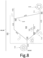
- the determining criterion for reducing cable breakages is not only the breaking force as is widely taught in the state of the art but the breaking energy represented in the present application by the area under the stress curve as a function of the elongation as shown in part on the figure 4 .
- the cables of the state of the art have either a relatively high breaking force but a relatively low breaking elongation, or a relatively high breaking elongation but a relatively low breaking force. In both cases, the cables of the state of the art break under a relatively low breaking energy indicator.
- the cable according to the invention due to its relatively low modulus, makes it possible to postpone the breaking elongation due to a relatively low slope of the stress-elongation curve in the elastic domain, which makes it possible to increase the breaking energy.
- Any interval of values designated by the expression "between a and b" represents the domain of values from greater than a to less than b (i.e., excluding the limits a and b) while any interval of values designated by the expression “from a to b” signifies the domain of values from the limit "a” to the limit "b", i.e., including the strict limits "a” and "b".
- This energy indicator at break represents a volumetric energy density in MJ/m 3 .
- a stress-elongation curve is drawn by applying the ASTM D 885/D 885M - 10a standard of 2014.
- the energy indicator at break Er is thus the sum of (1/2( ⁇ (Ai) + ⁇ (Ai+1)) x (Ai+1 - Ai) for i ranging from 0 to t.
- the sampling of the rectangles is defined such that the widths defined by (Ai+1 -Ai) are substantially equal to 0.025% or 4 rectangles for 0.1% elongation as shown in the figure 4 .
- tangent modulus E2 is calculated as follows on the force-elongation curve obtained under the conditions of ASTM D 885/D 885M - 10a of 2014: t E2 corresponds to the maximum tangent modulus of the cable on the force-elongation curve.
- the cable is two-layer stranded, that is, it comprises an assembly consisting of two layers of strands, no more and no less, that is, the assembly has two layers of strands, not one, not three, but only two.
- the outer layer of the cable is helically wound around the inner layer of the cable in contact with the inner layer of the cable.
- each inner strand and each outer strand is opposite to the winding direction of the cable.
- the winding direction of a layer of strands means the direction formed by the strands relative to the axis of the cable.
- the winding direction is commonly designated by the letter either Z or S.
- Each inner and outer strand is one layer of wires, that is, it comprises an assembly consisting of one layer of wires, no more and no less, that is, the assembly has one layer of wires, not zero, not two, but only one.
- each inner and outer strand is single-helix.
- a single-helix strand is a strand in which the axis of each metal wire element of the layer describes a single helix, unlike a double-helix strand in which the axis of each metal wire element describes a first helix around the axis of the strand and a second helix around a helix described by the axis of the strand.
- the strand when the strand extends in a substantially rectilinear direction, the strand comprises a single layer of metal wire elements wound together in a helix, each metal wire element of the layer describing a helix-shaped trajectory around a main axis substantially parallel to the substantially rectilinear direction such that, in a section plane substantially perpendicular to the main axis, the distance between the center of each wire element of the layer and the main axis is substantially constant and equal for all the wire elements of the layer.
- a double helix strand when a double helix strand extends in a substantially rectilinear direction, the distance between the center of each wire element of the layer and the substantially rectilinear direction is different for all the wire elements of the layer.
- wire element is meant an element extending longitudinally along a main axis and having a section perpendicular to the main axis whose largest dimension G is relatively small compared to the dimension L along the main axis.
- relatively small is meant that L/G is greater than or equal to 100, preferably greater than or equal to 1000.
- This definition covers both wire elements of circular section and wire elements of non-circular section, for example of polygonal or oblong section.
- each metal wire element has a circular section.
- metallic means a wire element consisting mainly (i.e. for more than 50% of its mass) or entirely (for 100% of its mass) of a metallic material.
- Each metallic wire element is preferably made of steel, more preferably of pearlitic or ferrito-pearlitic carbon steel, commonly called carbon steel by those skilled in the art, or even of stainless steel (by definition, steel containing at least 10.5% chromium).
- the metal wires and strands do not undergo preforming.
- the cable is obtained by a process devoid of individual preforming steps of each of the metal wire elements and each of the strands.
- the breaking energy indicator Er of the cable is greater than or equal to 42 MJ/ m3 , preferably greater than or equal to 50 MJ/ m3 and more preferably greater than or equal to 60 MJ/ m3 .
- the breaking energy indicator Er of the cable is less than or equal to 200 MJ/m 3
- the tangent modulus E2 ranges from 40 to 78 GPa and preferably from 40 to 75 GPa.
- the cable according to the invention has a minimum rigidity to allow the recovery or transmission of force.
- the polymer matrix is an elastomeric matrix.
- the polymeric matrix preferably elastomeric, is based on a polymeric composition, preferably elastomeric.
- polymer matrix is meant a matrix comprising at least one polymer.
- the polymer matrix is thus based on a polymer composition.
- elastomeric matrix a matrix comprising at least one elastomer.
- the preferred elastomeric matrix is thus based on the elastomeric composition.
- the composition comprises the mixture and/or the in situ reaction product of the different constituents used, some of these constituents being able to react and/or being intended to react with each other, at least partially, during the different phases of manufacture of the composition; the composition thus being able to be in a totally or partially crosslinked state or in a non-crosslinked state.
- polymeric composition that the composition comprises at least one polymer.
- a polymer may be a thermoplastic, for example a polyester or a polyamide, a thermosetting polymer, an elastomer, for example natural rubber, a thermoplastic elastomer or a mixture of these polymers.
- elastomeric composition comprises at least one elastomer and at least one other component.
- the composition comprising at least one elastomer and at least one other component comprises an elastomer, a crosslinking system and a filler.
- the compositions which can be used for these sheets are conventional compositions for calendering reinforcing wire elements and comprise a diene elastomer, for example natural rubber, a reinforcing filler, for example carbon black and/or silica, a crosslinking system, for example a vulcanization system, preferably comprising sulfur, stearic acid and zinc oxide, and optionally a vulcanization accelerator and/or retarder and/or various additives.
- the adhesion between the metal wires and the matrix in which they are embedded is ensured for example by a metallic coating, for example a layer of brass.
- the values of the characteristics described in the present application for the extracted cable are measured on or determined from cables extracted from a polymer matrix, in particular an elastomeric matrix, for example from a tire.
- a polymer matrix in particular an elastomeric matrix
- the strip of material is removed radially outside the cable to be extracted so as to see the cable to be extracted radially flush with the polymer matrix. This removal can be done by peeling using pliers and knives or by planing.
- the end of the cable to be extracted is released using a knife.
- the cable is pulled so as to extract it from the matrix by applying a relatively small angle so as not to plasticize the cable to be extracted.
- the extracted cables are then carefully cleaned, for example using a knife, so as to detach the remains of polymer matrix locally attached to the cable and taking care not to damage the surface of the metal wires.
- the tangent modulus E2' ranges from 22 to 70 GPa, preferably from 22 to 50 GPa and more preferably from 22 to 40 GPa.
- the breaking energy indicator Er' of the cable is greater than or equal to 50 MJ/m 3 , preferably greater than or equal to 55 MJ/m 3 and more preferably greater than or equal to 60 MJ/m 3
- the cable extracted according to the invention has a total elongation At' determined by the ASTM D2969-04 standard of 2014 such that At' ⁇ 5.0% and preferably At' ⁇ 6.0%.
- the total elongation At a quantity well known to those skilled in the art, is determined for example by applying the ASTM D2969-04 standard of 2014 to a cable tested so as to obtain a stress-elongation curve.
- the At' is deduced on the curve obtained as the elongation, in %, corresponding to the projection on the elongation axis of the breaking point of the cable on the stress-elongation curve, i.e. the point at which the load increases to a maximum stress value and then decreases abruptly after rupture.
- the decrease in relation to the stress exceeds a certain threshold, this means that the cable has ruptured.
- each internal and external strand is delimited by the metal wires and corresponds to the volume delimited by a theoretical circle, on the one hand, radially inside each metal wire element and, on the other hand, tangent to each metal wire element.
- the diameter of this theoretical circle is equal to the arch diameter Dvti for the wires of the internal strand and Dvte for the wires of the external strand.
- ⁇ fe 2 ⁇ ⁇ Rfe/Pfe.
- the helix diameter Dh corresponds to the diameter of the theoretical circle passing through the centers of the wire elements of the layer in a plane perpendicular to the main axis of the cable.
- Dhe Pfe ⁇ Tan( ⁇ fe) / ⁇ .
- the arch diameter of the outer strand Dvte Dhe-Dfe.
- the pitch at which each metallic wire element is wound is the length travelled by this wire element, measured parallel to the axis of the cable in which it is located, at the end of which the wire element having this pitch makes a complete turn around said axis of the cable.
- all the metal wire elements of the or each internal strand have the same diameter Dfi.
- all the metal wire elements of each external strand have the same diameter Dfe.
- the cable according to the invention has excellent longitudinal compressibility and, all things being equal, a relatively small diameter.
- the inventors behind the invention hypothesize that, due to a sufficiently high radius of curvature Rti relative to the diameter Dti of each internal strand, the cable is sufficiently ventilated, thereby reducing the risk of buckling, due to the relatively large distance of each internal strand from the longitudinal axis of the cable, a distance allowing the internal strands to accommodate, due to their helix, relatively high longitudinal compressive deformations.
- the cable according to the invention would have insufficient longitudinal rigidity in compression to ensure a reinforcement role, for example of tires.
- the cable would have, relative to the diameter of the internal strands, a diameter that is too high.
- the values of the characteristics Dti, Dvi and Rti as well as the other characteristics described below are measured on or determined from the cables either directly after manufacture, i.e. before any embedding step in an elastomeric matrix, or extracted from an elastomeric matrix, for example from a tire, and having then undergone a cleaning step during which any elastomeric matrix is removed from the cable, in particular any material present inside the cable.
- the adhesive interface between each metal wire element and the elastomeric matrix must be removed, for example by electrochemical process in a sodium carbonate bath.
- the arch of the cable according to the invention is delimited by the internal strands and corresponds to the volume delimited by a theoretical circle, on the one hand, radially inside each internal strand and, on the other hand, tangent to each internal strand.
- the diameter of this theoretical circle is equal to the arch diameter Dvi.
- the helix diameter De corresponds to the diameter of the theoretical circle passing through the centers of the internal strands of the layer in a plane perpendicular to the main axis of the cable.
- the pitch at which each internal strand is wound is the length travelled by this wire element, measured parallel to the axis of the cable in which it is located, at the end of which strand having this pitch makes a complete turn around said axis of the cable.
- Each strand is manufactured in accordance with a process and using an installation described in the documents WO2016083265 And WO2016083267 .
- Such a method implementing a splitting step is to be distinguished from a conventional wiring method comprising a single assembly step in which the metal wire elements are wound in a helix, the assembly step being preceded by a step of individual preforming of each metal wire element in order in particular to increase the value of the structural elongation.
- Such methods and installations are described in the documents EP0548539 , EP1000194 , EP0622489 , WO2012055677 , JP2007092259 , WO2007128335 , JPH06346386 or even EP0143767 .
- the metal monofilaments are individually preformed.
- this step of individual preforming of the metal monofilaments which requires a special installation, on the one hand, makes the process relatively unproductive compared to a process without an individual preforming step without however making it possible to achieve high structural elongations and, on the other hand, alters the metal monofilaments thus preformed due to friction with the preforming tools.
- Such alteration creates incipient breaks on the surface of the metal monofilaments and is therefore detrimental to the endurance of the metal monofilaments, in particular to their endurance in compression.
- the absence or presence of such preforming marks can be observed under an electron microscope at the end of the manufacturing process, or more simply, by knowing the manufacturing process of the cable.
- each wire element of the cable is free of pre-forming marks.
- Such pre-forming marks include, in particular, flats.
- the pre-forming marks also include cracks extending in cutting planes substantially perpendicular to the main axis along which each wire element extends. Such cracks extend, in a cutting plane substantially perpendicular to the main axis, from a radially external surface of each wire element radially towards the inside of each wire element. As described above, such cracks are initiated by the mechanical pre-forming tools due to bending forces, i.e. perpendicular to the main axis of each wire element, which makes them very detrimental to endurance.
- the cable has a diameter D such that D ⁇ 8.00 mm and preferably D ⁇ 7.00 mm.
- the diameter or apparent diameter, noted D is measured by wedging the cable between two perfectly straight bars of length 200 mm and by measuring the spacing in which the cable is embedded using the comparator described below.
- the measurement protocol consists of three repetitions of a series of three measurements (carried out perpendicular to the axis of the cable and under zero tension).
- each wire element comprises a single metal monofilament.
- each wire element advantageously consists of a metal monofilament.
- the metal monofilament is directly coated with a layer of a metal coating comprising copper, zinc, tin, cobalt or an alloy of these metals, for example brass or bronze.
- each wire element then consists of the metal monofilament, for example steel, forming a core, directly coated with the layer of metal coating.
- each elementary metallic monofilament is, as described above, preferably made of steel, and has a mechanical strength ranging from 1000 MPa to 5000 MPa.
- Such mechanical strengths correspond to the steel grades commonly encountered in the field of tires, namely, grades NT (Normal Tensile), HT (High Tensile), ST (Super Tensile), SHT (Super High Tensile), UT (Ultra Tensile), UHT (Ultra High Tensile) and MT (Mega Tensile), the use of high mechanical strengths possibly allowing improved reinforcement of the matrix in which the cable is intended to be embedded and a lightening of the matrix thus reinforced.
- the most severe transverse forces are the transverse forces exerted by the external strands on the internal strand.
- the low modulus E2 will relieve the contact pressures towards the internal strand while ensuring good breaking energy.
- Q 3 to 12
- Q 5, 6, 7 or 11.
- Q' would be equal to 1
- Q' would be equal to 1
- each metal wire respectively has a diameter ranging from 0.10 mm to 0.60 mm, preferably from 0.12 mm to 0.50 mm and more preferably from 0.15 mm to 0.46 mm.
- all the metal wires have the same diameter.
- the separation step and the reassembly step are carried out so that M1'+M2' ⁇ M'.
- the separation step and the reassembly step are carried out so that N1'+N2' ⁇ N'.
- transient core is separated into two parts each going with the first and second assemblies in cases where M' ⁇ 6, M1' ⁇ 0.70 ⁇ M' and M2' ⁇ 0.70 ⁇ M' and similarly, in cases where N' ⁇ 6, N1' ⁇ 0.70 ⁇ N' and N2' ⁇ 0.70 ⁇ N'.
- the step of providing the transient assembly comprises a step of assembly by twisting the M'>1 metal wire elements wound in a helix around the transient core and a step of assembly by twisting the N'>1 metal wire elements wound in a helix around the transient core.
- the step of providing the transient assembly comprises a step of balancing the transient assembly.
- the balancing step being carried out on the transient assembly comprising the M' metallic wire elements and the transient core, the balancing step is implicitly carried out upstream of the separation step between the first and second split assemblies. This avoids having to manage the residual twist imposed during the assembly step of the transient assembly during the path of the different assemblies downstream of the assembly step, in particular in the guide means, for example the pulleys.
- the balancing step being carried out on the transient assembly comprising the N' metallic wire elements.
- the method comprises a step of balancing the final assembly downstream of the reassembly step.
- the method comprises a step of maintaining the rotation of the final assembly around its running direction.
- This rotation maintenance step is carried out downstream of the step of separating the transient assembly and upstream of the step of balancing the final assembly.
- the method is free of individual preforming steps for each of the wire elements.
- the latter are given a shape by preforming tools, for example rollers, these tools creating defects on the surface of the wire elements. These defects significantly reduce the endurance of the wire elements and therefore of the final assembly.
- the transitional core is a metal wire element.
- the transitional core is a metal monofilament.
- the diameter of the space between the metal wire elements and therefore the geometric characteristics of the final assembly are very precisely controlled, unlike a transitional core made of a textile material, for example polymeric, the compressibility of which can generate variations in the geometric characteristics of the final assembly.
- the transitional core is a textile filament element.
- a textile filament element comprises at least one multifilament textile strand or, alternatively, is made of a textile monofilament.
- the filaments textiles that can be used are chosen from polyesters, polyketones, aliphatic or aromatic polyamides and mixtures of textile filaments of these materials. This reduces the risks of breakage of the transitional core caused by friction of the metal wire elements on the transitional core as well as by the twists imposed on the transitional core.
- the invention also relates to a reinforced product comprising a polymer matrix and at least one extracted cable as defined above.
- the reinforced product comprises one or more cables according to the invention embedded in the polymer matrix, and in the case of several cables, the cables are arranged side by side in a main direction.
- the invention also relates to a tire comprising at least one extracted cable as defined above or a reinforced product as defined above.
- the tire comprises a carcass reinforcement anchored in two beads and surmounted radially by a crown reinforcement itself surmounted by a tread, the crown reinforcement being joined to said beads by two sidewalls and comprising at least one cable as defined above.
- the crown reinforcement comprises a protective reinforcement and a working reinforcement, the working reinforcement comprising at least one cable as defined above, the protective reinforcement being radially interposed between the tread and the working reinforcement.
- the cable is particularly intended for industrial vehicles selected from heavy vehicles such as "Heavy goods vehicles” - i.e., metro, bus, road transport vehicles (trucks, tractors, trailers), off-road vehicles -, agricultural or civil engineering vehicles, other transport or handling vehicles.
- heavy vehicles such as "Heavy goods vehicles” - i.e., metro, bus, road transport vehicles (trucks, tractors, trailers), off-road vehicles -, agricultural or civil engineering vehicles, other transport or handling vehicles.
- the tire is for civil engineering type vehicles.
- the tire has a dimension in which the diameter, in inches, of the seat of the rim on which the tire is intended to be mounted is greater than or equal to 40 inches.
- the invention also relates to a rubber article comprising an assembly according to the invention, or an impregnated assembly according to the invention.
- rubber article is meant any type of rubber article such as a ball, a non-pneumatic object such as a non-pneumatic tire, a conveyor belt or a caterpillar.
- the “median circumferential plane” M of the tire is the plane which is normal to the axis of rotation of the tire and which is located equidistant from the annular reinforcement structures of each bead.
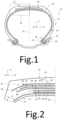
- the P tire is for heavy civil engineering type vehicles, for example “dumper” type.
- the P tire has a dimension of type 53/80R63.
- the tire P comprises a crown 12 reinforced by a crown reinforcement 14, two sidewalls 16 and two beads 18, each of these beads 18 being reinforced with an annular structure, here a bead wire 20.
- the crown reinforcement 14 is radially surmounted by a tread 22 and joined to the beads 18 by the sidewalls 16.
- a carcass reinforcement 24 is anchored in the two beads 18, and is here wound around the two bead wires 20 and comprises a turn-up 26 arranged towards the outside of the tire 20 which is here shown mounted on a rim 28.
- the carcass reinforcement 24 is radially surmounted by the crown reinforcement 14.
- the carcass reinforcement 24 comprises at least one carcass ply 30 reinforced by radial carcass cords (not shown).
- the carcass cords are arranged substantially parallel to each other and extend from one bead 18 to the other so as to form an angle of between 80° and 90° with the median circumferential plane M (plane perpendicular to the axis of rotation of the tire which is located midway between the two beads 18 and passes through the middle of the crown reinforcement 14).
- the tire P also comprises a sealing ply 32 made of an elastomer (commonly called inner rubber) which defines the radially internal face 34 of the tire P and which is intended to protect the carcass ply 30 from the diffusion of air coming from the space inside the tire P.
- a sealing ply 32 made of an elastomer (commonly called inner rubber) which defines the radially internal face 34 of the tire P and which is intended to protect the carcass ply 30 from the diffusion of air coming from the space inside the tire P.
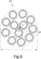
- the crown reinforcement 14 comprises, radially from the outside to the inside of the tire P, a protective reinforcement 36 arranged radially inside the tread 22, a working reinforcement 38 arranged radially inside the protective reinforcement 36 and an additional reinforcement 40 arranged radially inside the working reinforcement 38.
- the protective reinforcement 36 is thus radially intercalated between the tread 22 and the working reinforcement 38.
- the working reinforcement 38 is radially intercalated between the protective reinforcement 36 and the additional reinforcement 40.
- the protective frame 36 comprises first and second protective plies 42, 44 comprising protective metal cables, the first ply 42 being arranged radially inside the second ply 44.
- the protective metal cables make an angle at least equal to 10°, preferably ranging from 10° to 35° and preferentially from 15° to 30° with the circumferential direction Z of the tire.
- the working reinforcement 38 comprises first and second working plies 46, 48, the first ply 46 being arranged radially inside the second ply 48.
- Each ply 46, 48 comprises at least one cable 50.
- the working metal cables 50 are crossed from one working ply to the other and make an angle at most equal to 60°, preferably ranging from 15° to 40° with the circumferential direction Z of the tire.
- the additional frame 40 also called a limiter block, the function of which is to partially absorb the mechanical stresses of inflation, comprises, for example and in a manner known per se, additional metal reinforcement elements, for example as described in FR 2 419 181 Or FR 2 419 182 making an angle of at most 10°, preferably ranging from 5° to 10° with the circumferential direction Z of the tire P.
- the reinforced product R comprises at least one 50' cable, in this case several 50' cables, embedded in the polymer matrix Ma.
- the polymer matrix Ma the cables 50' are represented in a reference frame X, Y, Z in which the direction Y is the radial direction and the directions X and Z are the axial and circumferential directions.
- the reinforced product R comprises several 50' cables arranged side by side in the main direction X and extending parallel to each other within the reinforced product R and collectively embedded in the matrix polymeric Ma.
- the polymer matrix Ma is an elastomeric matrix based on an elastomeric composition.
- Each protective reinforcement element 43, 45 and each hoop reinforcement element 53, 55 is formed, after extraction of the tire 10, by an extracted cable 50' as described below.
- the cable 50 is obtained by embedding in a polymer matrix, in this case in a polymer matrix respectively forming each polymer matrix of each protective ply 42, 44 and of each hoop layer 52, 54 in which the protective reinforcement elements 43, 45 and hoop elements 53, 55 are respectively embedded.
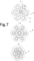
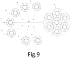
- the 50 cable and the 50' extracted cable are metallic and of the multi-strand type with two cylindrical layers.
- the layers of strands constituting the 50 or 50' cable are two in number, no more, no less.
- the cable 50 or the cable 50' comprises an inner layer CI of the cable consisting of K ⁇ 1 inner strand(s) TI wound helically around a main axis (A), the or each inner strand TI being at a layer C1 of metal wires F1 and comprising Q>1 metal wires F1 wound helically around an axis (B); and an outer layer CE of the cable consisting of L>1 outer strands TE wound around the inner layer CI of the cable, each outer strand TE being at a layer C1' of metal wires F1' and comprising Q'>1 metal wires F1' wound helically around an axis (B').
- the stress-strain curve of the cable 50 is plotted using ASTM D 885/D 885M - 10a of 2014. From this stress-strain curve, the area under this curve is deduced. The following is shown in the figure: figure 4 the rectangle method for determining the breaking energy indicator of cable 50.
- the tangent modulus E2 is determined from this same curve by relating it to the section of the cable 50.
- the internal strand TI of the internal layer CI is manufactured: the wire elements F1 and the transient core 16 are unwound from the supply means.
- the method comprises a step 100 of providing the transient assembly 22 comprising on the one hand a step of assembly by twisting the M' metallic wire elements F1 into a single layer of M' metallic wire elements F1 around the transient core 16 and on the other hand, a step of balancing the transient assembly 22 carried out using a twister.
- the method comprises a step 110 of separating the transient assembly 22 between the first split assembly 25, the second split assembly 27 and the transient core 16 or one or more assemblies comprising the transient core 16, here the transient core 16.
- the separation step 110 of the assembly transient 22 between the first split assembly 25, the second split assembly 27 and the transient core 16 comprises a step 120 of separating the transient assembly 22 between the precursor assembly, the second split assembly 27 and finally the transient core 16.
- the separation step 120 of the transient assembly between the precursor assembly and the split assembly comprises a step 124 of separating the split assembly between the second split assembly 27 and the transient core 16.
- the separation step 124 comprises a step of splitting the split assembly into the second split assembly 27, the transient core 16 and the complementary assembly.
- the step 110 of separating the transient assembly between the first split assembly 25, the second split assembly 27 and the transient core 16 comprises a step 130 of separating the precursor assembly between the first split assembly 25 and the complementary assembly.
- the method comprises a step 140 of reassembling the first split assembly 25 with the second split assembly 27 to form the strand 54.
- the supply step 100, the separation step 110 and the reassembly step 140 are carried out so that all the M' metallic wire elements F1 have the same diameter Dfi, are wound in a helix according to the same pitch Pi and have the same helix radius Rfi described previously.
- the separation step 110 and the reassembly step 140 are carried out so that M1'+M2' ⁇ M'.
- a final balancing step is carried out.
- the inner strand is stored on a storage reel.
- the method comprises a step of recycling the transient core 16.
- the transient core 16 is recovered downstream of the separation step 110, here downstream of the separation step 124, and the transient core 16 recovered previously is introduced upstream of the assembly step.
- This recycling step is continuous.
- Tables 1, 2 and 3 below summarize the characteristics for the different cables 50, 50', 60, 60', 51, 52, 53, 53', 54 according to the invention and for the state-of-the-art cables EDT1, EDT1', EDT2 and EDT2'.
- the stress-strain curves of the cables were plotted by applying the ASTM D 885/D 885M - 10a standard of 2014 and the E2 modulus and the breaking energy indicator were determined for the different cables 50, 50', 60, 60', 51, 52, 53, 53' according to the invention and for the state-of-the-art cables EDT1 and EDT1'.
- Tables 1, 2 and 3 show that the cables 50, 50', 60, 60', 51, 52, 53 and 53' according to the invention have both improved breaking energy and have better deformability due to their relatively low modulus compared to the state-of-the-art cables EDT1 and EDT1'.
- the cables according to the invention make it possible to solve the problems mentioned in the preamble.
Landscapes
- Ropes Or Cables (AREA)
- Insulated Conductors (AREA)
Claims (15)
- Mehrlitziges Metallseil (50; 60) mit zwei Lagen, umfassend:- eine innere Lage (CI) des Seils, die aus K ≥ 1 inneren Litze(n) (TI) besteht, die helixartig um eine Hauptachse (A) gewunden sind, wobei die oder jede innere Litze (TI) eine Lage (C1) aus Metalldrähten (F1) aufweist und Q > 1 Metalldrähte (F1) umfasst, die helixartig um eine Achse (B) gewunden sind; und- eine äußere Lage (CE) des Seils, die aus L > 1 äußeren Litzen (TE) besteht, die um die innere Lage (CI) des Seils gewunden sind, wobei jede äußere Litze (TE) eine Lage (C1') aus Metalldrähten (F1') aufweist und Q' > 1 Metalldrähte (F1') umfasst, die helixartig um eine Achse (B') gewunden sind,dadurch gekennzeichnet, dass:- das Seil (50 ; 60) einen Tangentenmodul E2 von 35 bis 80 GPa aufweist; und- der Bruchenergieindikator Er des Seils (50, 60), der durch

- Seil (50; 60) nach dem vorhergehenden Anspruch, wobei der Bruchenergieindikator Er des Seils (50; 60) größer als oder gleich 42 MJ/m3, bevorzugt größer als oder gleich 50 MJ/m3 und besonders bevorzugt größer als oder gleich 60 MJ/m3 ist.
- Seil (50; 60) nach einem der vorhergehenden Ansprüche, wobei der Bruchenergieindikator Er des Seils (50) kleiner als oder gleich 200 MJ/m3 ist.
- Seil (50; 60)) nach einem der vorhergehenden Ansprüche, wobei der Tangentenmodul E2 von 40 bis 78 GPa und bevorzugt von 40 bis 75 GPa reicht.
- Mehrlitziges Seil mit zwei Lagen (50'; 60'), das aus einer Polymermatrix herausgezogen wurde, wobei das herausgezogene Seil (50'; 60') umfasst:- eine innere Lage (CI) des Seils, die aus K ≥ 1 inneren Litze(n) (TI) besteht, die helixartig um eine Hauptachse (A) gewunden sind, wobei die oder jede innere Litze (TI) eine Lage (C1) aus Metalldrähten (F1) aufweist und Q > 1 Metalldrähte umfasst, die helixartig um eine Achse (B) gewunden sind; und- eine äußere Lage (CE) des Seils, die aus L > 1 äußeren Litzen (TE) besteht, die um die innere Lage (CI) des Seils gewunden sind, wobei jede äußere Litze (TE) eine Lage (C1') aus Metalldrähten (F1') aufweist und Q' > 1 Metalldrähte umfasst, die helixartig um eine Achse (B') gewunden sind,dadurch gekennzeichnet, dass:- das herausgezogene Seil (50'; 60') einen Tangentenmodul E2' von 20 bis 80 GPa aufweist;- der Bruchenergieindikator Er' des herausgezogenen Seils (50'), der durch

- Herausgezogenes Seil (50'; 60') nach dem vorhergehenden Anspruch, wobei der Tangentenmodul E2' von 22 bis 70 GPa, bevorzugt von 22 bis 50 GPa und besonders bevorzugt von 22 bis 40 GPa reicht.
- Herausgezogenes Seil (50'; 60') nach einem der Ansprüche 4 bis 6, wobei der Bruchenergieindikator Er' des Seils (50) größer als oder gleich 50 MJ/m3, bevorzugt größer als oder gleich 55 MJ/m3 und besonders bevorzugt größer als oder gleich 60 MJ/m3 ist.
- Herausgezogenes Seil (50'; 60') nach Anspruch 4 oder 5, das eine derartige Gesamtdehnung At', bestimmt durch die Norm ASTM D2969-04 von 2014, aufweist, dass At' ≥ 5,0 % und bevorzugt At' ≥ 6,0 %.
- Seil (50; 60) nach einem der Ansprüche 1 bis 4 oder herausgezogenes Seil (50'; 60') nach einem der Ansprüche 5 bis 8, wobei die Metalldrahtelemente (F1; F1') ein inneres Gewölbe (59; 59') jeder inneren und äußeren Litze (TI; TE) mit dem Durchmesser Dvti bzw. Dvte definieren, wobei jedes Metalldrahtelement (F1; F1') einen Durchmesser Dfi bzw. Dfe und einen Helixkrümmungsradius Rfi bzw. Rfe aufweist, die durch Rfi = Pi/(π × Sin(2αi)) definiert werden, wobei Pi die in Millimetern ausgedrückte Steigung jedes Metalldrahtelements der inneren Litze (TI) und αi der Helixwinkel jedes Metalldrahtelements (F1) ist, und Rfe = Pe/(π × Sin(2αe)), wobei Pe die in Millimeter ausgedrückte Steigung jedes Metalldrahtelements der äußeren Litze (TE) und αe der Helixwinkel jedes Metalldrahtelements (F1') ist, wobei Dvti, Dvte, Dfi, Dfe und Rfi, Rfe in Millimetern ausgedrückt werden, wobei das Seil (50; 60) oder das herausgezogene Seil (50'; 60') die folgenden Gleichungen erfüllt:


- Seil (60) nach einem der Ansprüche 1 bis 4 oder herausgezogenes Seil (60') nach einem der Ansprüche 5 bis 8, wobei, wenn K > 1, die inneren Litzen (TI) ein inneres Gewölbe (68) des Seils (60 ;60') mit dem Durchmesser Dvi definieren, wobei jede innere Litze (TI) einen Durchmesser Dti und einen Helixkrümmungsradius Rti aufweist, wobei Rti durch Rti = Pti/(n × Sin(2αti)) definiert ist, wobei Pti die in Millimetern ausgedrückte Steigung jeder inneren Litze und αti der Helixwinkel jeder inneren Litze (TI) ist, wobei Dvi, Dti und Rti in Millimetern ausgedrückt werden, wobei das Seil (60) oder das herausgezogene Seil (60') die folgenden Gleichungen erfüllt:

- Verfahren zur Herstellung eines Seils (50; 60) nach einem der Ansprüche 1 bis 4 und 9 bis 10, dadurch gekennzeichnet, dass es umfasst:- einen Schritt des Herstellens (200) der K inneren Litze(n) (TI) durch:∘ einen Schritt (100) des Bereitstellens eines Übergangsverbands (22), umfassend eine Lage, die aus M'>1 helixartig um einen Übergangskern (16) gewundenen Metalldrähten (F1) besteht,∘ einen Schritt (110) des Trennens des Übergangsverbands (22) in:▪ einen ersten fraktionierten Verband (25), umfassend eine Lage (26), die aus M1' ≥ 1 Metalldraht/-drähten (F1) besteht, der/die helixartig gewunden ist/sind, wobei der oder die M1' Metalldraht/-drähte (F1) aus der aus M' > 1 Metalldrähten (F1) bestehenden Lage des Übergangsverbands (22) stammt/stammen,▪ einen zweiten fraktionierten Verband (27), umfassend eine Lage (28), die aus M2' > 1 helixartig gewundenen Metalldrähten (F1) besteht, wobei die M2' Metalldrähte (F1) aus der aus M' > 1 Metalldrähten bestehenden Lage des Übergangsverbands (22) stammen,▪ den Übergangskern (16) oder eine oder mehrere Anordnungen (83), die den Übergangskern (16) umfassen,∘ einen Schritt (140) des Wiederzusammensetzens des ersten fraktionierten Verbands (25) mit dem zweiten fraktionierten Verband (27), um eine innere Litze (TI) mit einer Lage aus Metalldrähten (F1) und umfassend Q > 1 Metalldrähte (F1) zu bilden;- einen Schritt des Herstellens (200') der L äußeren Litzen (TE) durch:∘ einen Schritt (100') des Bereitstellens eines Übergangsverbands (22'), umfassend eine Lage, die aus N'>1 helixartig um einen Übergangskern (16') gewundenen Metalldrähten (F1') besteht,∘ einen Schritt (110') des Trennens des Übergangsverbands (22') in:▪ einen ersten fraktionierten Verband (25'), umfassend eine Lage (26), die aus N1' ≥ 1 Metalldraht/- drähten (F1') besteht, der/die helixartig gewunden ist/sind, wobei der oder die N1' Metalldraht/-drähte (F1') aus der aus N'>1 Metalldrähten (F1') bestehenden Lage des Übergangsverbands (22') stammt/stammen,▪ einen zweiten fraktionierten Verband (27'), umfassend eine Lage (28'), die aus N2' > 1 helixartig gewundenen Metalldrähten (F1') besteht, wobei die N2' Metalldrähte (F1') aus der aus N'>1 Metalldrähten (F1') bestehenden Lage des Übergangsverbands (22') stammen,▪ den Übergangskern (16') oder eine oder mehrere Anordnungen (83'), die den Übergangskern (16') umfassen,∘ einen Schritt (140') des Wiederzusammensetzens des ersten fraktionierten Verbands (25') mit dem zweiten fraktionierten Verband (27'), um eine äußere Litze (TE) mit einer Lage aus Metalldrähten (F1') und umfassend Q' > 1 Metalldrähte (F1') zu bilden;- einen Schritt des Zusammensetzens (300) durch Verseilen der K inneren Litze(n) (TI), um die innere Lage (CI) zu bilden, dann der L äußeren Litzen (TE) um die innere Lage (CI), um das Seil (50; 60) zu bilden.
- Verfahren nach dem vorhergehenden Anspruch, bei dem Q = M1' + M2' von 3 bis 18 und bevorzugt von 4 bis 15 reicht.
- Verfahren nach Anspruch 11 oder 12, bei dem Q' - N1' + N2' von 3 bis 18 und bevorzugt von 4 bis 15 reicht.
- Verstärktes Produkt (R), dadurch gekennzeichnet, dass es eine Polymermatrix (Ma) und mindestens ein herausgezogenes Seil (50'; 60') nach einem der Ansprüche 5 bis 10 umfasst.
- Reifen (P), dadurch gekennzeichnet, dass er mindestens ein herausgezogenes Seil (50 ; 60') nach einem der Ansprüche 5 bis 10 oder ein verstärktes Produkt nach Anspruch 14 umfasst.
Applications Claiming Priority (2)
| Application Number | Priority Date | Filing Date | Title |
|---|---|---|---|
| FR2000100 | 2020-01-07 | ||
| PCT/FR2020/052527 WO2021140288A1 (fr) | 2020-01-07 | 2020-12-18 | Câble multi-torons à deux couches à énergie à rupture améliorée et à module tangent bas |
Publications (2)
| Publication Number | Publication Date |
|---|---|
| EP4087971A1 EP4087971A1 (de) | 2022-11-16 |
| EP4087971B1 true EP4087971B1 (de) | 2024-08-28 |
Family
ID=70154625
Family Applications (1)
| Application Number | Title | Priority Date | Filing Date |
|---|---|---|---|
| EP20845791.1A Active EP4087971B1 (de) | 2020-01-07 | 2020-12-18 | Doppellagiges mehradriges kabel, das eine verbesserte bruchenergie und einen niedrigen tangentenmodul aufweist |
Country Status (4)
| Country | Link |
|---|---|
| EP (1) | EP4087971B1 (de) |
| CN (1) | CN115003878B (de) |
| CA (1) | CA3161403A1 (de) |
| WO (1) | WO2021140288A1 (de) |
Family Cites Families (18)
| Publication number | Priority date | Publication date | Assignee | Title |
|---|---|---|---|---|
| FR2001714A1 (de) * | 1968-02-12 | 1969-10-03 | Pirelli | |
| FR2419181A1 (fr) | 1978-03-10 | 1979-10-05 | Michelin & Cie | Perfectionnements aux pneumatiques a carcasse radiale |
| FR2419182A1 (fr) | 1978-03-10 | 1979-10-05 | Michelin & Cie | Pneumatique a carcasse radiale, notamment pour engins de genie civil |
| JPS6059188A (ja) | 1983-09-02 | 1985-04-05 | ブリヂストン・ベカルト・スチ−ル・コ−ド株式会社 | ゴム物品補強用スチ−ルコ−ド |
| JPH0768673B2 (ja) | 1991-12-27 | 1995-07-26 | トクセン工業株式会社 | ゴム製品補強用スチールコード |
| DE4314172C1 (de) | 1993-04-29 | 1994-09-15 | Witels App Masch Albert Gmbh | Vorformkopf für Seile und Kabelarmierungen |
| JPH06346386A (ja) | 1993-06-02 | 1994-12-20 | Sumitomo Electric Ind Ltd | ゴム物品補強用金属コード |
| JP2001512191A (ja) | 1997-07-29 | 2001-08-21 | ナムローゼ・フェンノートシャップ・ベーカート・ソシエテ・アノニム | 空気タイヤの保護プライ用スチールコード |
| JP4646770B2 (ja) | 2005-09-30 | 2011-03-09 | 金井 宏彰 | スチールコードおよび自動車用タイヤ |
| US7775247B2 (en) * | 2005-12-22 | 2010-08-17 | The Goodyear Tire & Rubber Company | Steel cord for reinforcement of off-the-road tires |
| JP5078055B2 (ja) * | 2006-01-20 | 2012-11-21 | 株式会社ブリヂストン | ゴム−スチールコード複合体 |
| US7975463B2 (en) | 2006-05-10 | 2011-07-12 | Pirelli Tyre S.P.A. | Metal cord and process for manufacturing a metal cord |
| FR2943951B1 (fr) * | 2009-04-07 | 2012-12-14 | Michelin Soc Tech | Pneumatique pour vehicules lourds comportant une couche d'elements de renforcement circonferentiels. |
| EP2700746B1 (de) * | 2009-04-28 | 2016-12-14 | Bridgestone Corporation | Stahlseil zur Verstärkung eines Kautschukprodukts und Luftreifen |
| WO2012055677A2 (en) | 2010-10-27 | 2012-05-03 | Nv Bekaert Sa | Open steel cord |
| FR3028873B1 (fr) | 2014-11-25 | 2016-12-23 | Michelin & Cie | Installation de fractionnement |
| FR3028872B1 (fr) | 2014-11-25 | 2017-05-19 | Michelin & Cie | Procede de fractionnement |
| EP3420137A1 (de) * | 2016-02-23 | 2019-01-02 | NV Bekaert SA | Energieaufnahmeanordnung |
-
2020
- 2020-12-18 CA CA3161403A patent/CA3161403A1/fr active Pending
- 2020-12-18 WO PCT/FR2020/052527 patent/WO2021140288A1/fr not_active Ceased
- 2020-12-18 CN CN202080093681.4A patent/CN115003878B/zh active Active
- 2020-12-18 EP EP20845791.1A patent/EP4087971B1/de active Active
Also Published As
| Publication number | Publication date |
|---|---|
| CA3161403A1 (fr) | 2021-07-15 |
| EP4087971A1 (de) | 2022-11-16 |
| CN115003878B (zh) | 2023-03-21 |
| CN115003878A (zh) | 2022-09-02 |
| WO2021140288A1 (fr) | 2021-07-15 |
Similar Documents
| Publication | Publication Date | Title |
|---|---|---|
| EP4087970B1 (de) | Einlagiges mehradriges kabel, das eine verbesserte reissdehnung und verbesserte gesamtdehnung aufweist | |
| EP4061996B1 (de) | Zweischichtiges mehradriges kabel mit einer verbesserten oberflächenenergie bis zum bruch | |
| EP4172406B1 (de) | Zweischichtiges mehradriges kabel mit verbesserter biegefestigkeit | |
| EP4087971B1 (de) | Doppellagiges mehradriges kabel, das eine verbesserte bruchenergie und einen niedrigen tangentenmodul aufweist | |
| EP4172405B1 (de) | Zweischichtiges mehradriges kabel mit verbesserter biegefestigkeit | |
| EP4172407B1 (de) | Zweischichtiges mehradriges kabel mit verbesserter biegefestigkeit | |
| EP4172408B1 (de) | Zweischichtiges mehradriges kabel mit verbesserter biegefestigkeit | |
| FR3156458A1 (fr) | Câble à une couche à énergie à rupture améliorée et à allongement total amélioré | |
| FR3122674A1 (fr) | Câble multi-torons à deux couches à énergie de rupture surfacique améliorée | |
| FR3122673A1 (fr) | Câble multi-torons à deux couches à énergie de rupture surfacique améliorée | |
| FR3122675A1 (fr) | Câble multi-torons à deux couches à énergie de rupture surfacique améliorée | |
| FR3130858A1 (fr) | Câble multi-torons à deux couches à endurance sous flexion améliorée | |
| FR3122678A1 (fr) | Câble multi-torons à deux couches à énergie de rupture surfacique améliorée | |
| FR3122676A1 (fr) | Câble multi-torons à deux couches à énergie de rupture surfacique améliorée | |
| FR3122672A1 (fr) | Câble multi-torons à deux couches à énergie de rupture surfacique améliorée | |
| FR3122677A1 (fr) | Câble multi-torons à deux couches à énergie de rupture surfacique améliorée | |
| FR3156457A1 (fr) | Câble extrait à une couche à répartition optimisée des fils | |
| WO2022096799A1 (fr) | Câble multi-torons à deux couches avec couche interne gainée à pénétrabilité améliorée | |
| WO2025008148A1 (fr) | Câble multi-torons à deux couches de multi-torons | |
| WO2021094675A1 (fr) | Câble multi-torons à deux couches avec couche interne gainée à pénétrabilité améliorée | |
| FR3136788A1 (fr) | Câble multi-torons à deux couches de multi-torons |
Legal Events
| Date | Code | Title | Description |
|---|---|---|---|
| STAA | Information on the status of an ep patent application or granted ep patent |
Free format text: STATUS: UNKNOWN |
|
| STAA | Information on the status of an ep patent application or granted ep patent |
Free format text: STATUS: THE INTERNATIONAL PUBLICATION HAS BEEN MADE |
|
| PUAI | Public reference made under article 153(3) epc to a published international application that has entered the european phase |
Free format text: ORIGINAL CODE: 0009012 |
|
| STAA | Information on the status of an ep patent application or granted ep patent |
Free format text: STATUS: REQUEST FOR EXAMINATION WAS MADE |
|
| 17P | Request for examination filed |
Effective date: 20220808 |
|
| AK | Designated contracting states |
Kind code of ref document: A1 Designated state(s): AL AT BE BG CH CY CZ DE DK EE ES FI FR GB GR HR HU IE IS IT LI LT LU LV MC MK MT NL NO PL PT RO RS SE SI SK SM TR |
|
| DAV | Request for validation of the european patent (deleted) | ||
| DAX | Request for extension of the european patent (deleted) | ||
| STAA | Information on the status of an ep patent application or granted ep patent |
Free format text: STATUS: EXAMINATION IS IN PROGRESS |
|
| 17Q | First examination report despatched |
Effective date: 20230808 |
|
| GRAP | Despatch of communication of intention to grant a patent |
Free format text: ORIGINAL CODE: EPIDOSNIGR1 |
|
| STAA | Information on the status of an ep patent application or granted ep patent |
Free format text: STATUS: GRANT OF PATENT IS INTENDED |
|
| INTG | Intention to grant announced |
Effective date: 20240424 |
|
| GRAS | Grant fee paid |
Free format text: ORIGINAL CODE: EPIDOSNIGR3 |
|
| GRAA | (expected) grant |
Free format text: ORIGINAL CODE: 0009210 |
|
| STAA | Information on the status of an ep patent application or granted ep patent |
Free format text: STATUS: THE PATENT HAS BEEN GRANTED |
|
| AK | Designated contracting states |
Kind code of ref document: B1 Designated state(s): AL AT BE BG CH CY CZ DE DK EE ES FI FR GB GR HR HU IE IS IT LI LT LU LV MC MK MT NL NO PL PT RO RS SE SI SK SM TR |
|
| REG | Reference to a national code |
Ref country code: CH Ref legal event code: EP |
|
| REG | Reference to a national code |
Ref country code: DE Ref legal event code: R096 Ref document number: 602020036838 Country of ref document: DE |
|
| REG | Reference to a national code |
Ref country code: IE Ref legal event code: FG4D Free format text: LANGUAGE OF EP DOCUMENT: FRENCH |
|
| REG | Reference to a national code |
Ref country code: LT Ref legal event code: MG9D |
|
| PGFP | Annual fee paid to national office [announced via postgrant information from national office to epo] |
Ref country code: DE Payment date: 20241210 Year of fee payment: 5 |
|
| PG25 | Lapsed in a contracting state [announced via postgrant information from national office to epo] |
Ref country code: NO Free format text: LAPSE BECAUSE OF FAILURE TO SUBMIT A TRANSLATION OF THE DESCRIPTION OR TO PAY THE FEE WITHIN THE PRESCRIBED TIME-LIMIT Effective date: 20241128 |
|
| REG | Reference to a national code |
Ref country code: AT Ref legal event code: MK05 Ref document number: 1718063 Country of ref document: AT Kind code of ref document: T Effective date: 20240828 |
|
| PG25 | Lapsed in a contracting state [announced via postgrant information from national office to epo] |
Ref country code: PT Free format text: LAPSE BECAUSE OF FAILURE TO SUBMIT A TRANSLATION OF THE DESCRIPTION OR TO PAY THE FEE WITHIN THE PRESCRIBED TIME-LIMIT Effective date: 20241230 Ref country code: NL Free format text: LAPSE BECAUSE OF FAILURE TO SUBMIT A TRANSLATION OF THE DESCRIPTION OR TO PAY THE FEE WITHIN THE PRESCRIBED TIME-LIMIT Effective date: 20240828 Ref country code: GR Free format text: LAPSE BECAUSE OF FAILURE TO SUBMIT A TRANSLATION OF THE DESCRIPTION OR TO PAY THE FEE WITHIN THE PRESCRIBED TIME-LIMIT Effective date: 20241129 Ref country code: FI Free format text: LAPSE BECAUSE OF FAILURE TO SUBMIT A TRANSLATION OF THE DESCRIPTION OR TO PAY THE FEE WITHIN THE PRESCRIBED TIME-LIMIT Effective date: 20240828 Ref country code: PL Free format text: LAPSE BECAUSE OF FAILURE TO SUBMIT A TRANSLATION OF THE DESCRIPTION OR TO PAY THE FEE WITHIN THE PRESCRIBED TIME-LIMIT Effective date: 20240828 |
|
| PG25 | Lapsed in a contracting state [announced via postgrant information from national office to epo] |
Ref country code: BG Free format text: LAPSE BECAUSE OF FAILURE TO SUBMIT A TRANSLATION OF THE DESCRIPTION OR TO PAY THE FEE WITHIN THE PRESCRIBED TIME-LIMIT Effective date: 20240828 |
|
| PGFP | Annual fee paid to national office [announced via postgrant information from national office to epo] |
Ref country code: FR Payment date: 20241227 Year of fee payment: 5 |
|
| PG25 | Lapsed in a contracting state [announced via postgrant information from national office to epo] |
Ref country code: LV Free format text: LAPSE BECAUSE OF FAILURE TO SUBMIT A TRANSLATION OF THE DESCRIPTION OR TO PAY THE FEE WITHIN THE PRESCRIBED TIME-LIMIT Effective date: 20240828 |
|
| REG | Reference to a national code |
Ref country code: NL Ref legal event code: MP Effective date: 20240828 |
|
| PG25 | Lapsed in a contracting state [announced via postgrant information from national office to epo] |
Ref country code: AT Free format text: LAPSE BECAUSE OF FAILURE TO SUBMIT A TRANSLATION OF THE DESCRIPTION OR TO PAY THE FEE WITHIN THE PRESCRIBED TIME-LIMIT Effective date: 20240828 Ref country code: IS Free format text: LAPSE BECAUSE OF FAILURE TO SUBMIT A TRANSLATION OF THE DESCRIPTION OR TO PAY THE FEE WITHIN THE PRESCRIBED TIME-LIMIT Effective date: 20241228 |
|
| PG25 | Lapsed in a contracting state [announced via postgrant information from national office to epo] |
Ref country code: HR Free format text: LAPSE BECAUSE OF FAILURE TO SUBMIT A TRANSLATION OF THE DESCRIPTION OR TO PAY THE FEE WITHIN THE PRESCRIBED TIME-LIMIT Effective date: 20240828 |
|
| PG25 | Lapsed in a contracting state [announced via postgrant information from national office to epo] |
Ref country code: RS Free format text: LAPSE BECAUSE OF FAILURE TO SUBMIT A TRANSLATION OF THE DESCRIPTION OR TO PAY THE FEE WITHIN THE PRESCRIBED TIME-LIMIT Effective date: 20241128 Ref country code: ES Free format text: LAPSE BECAUSE OF FAILURE TO SUBMIT A TRANSLATION OF THE DESCRIPTION OR TO PAY THE FEE WITHIN THE PRESCRIBED TIME-LIMIT Effective date: 20240828 |
|
| PG25 | Lapsed in a contracting state [announced via postgrant information from national office to epo] |
Ref country code: RS Free format text: LAPSE BECAUSE OF FAILURE TO SUBMIT A TRANSLATION OF THE DESCRIPTION OR TO PAY THE FEE WITHIN THE PRESCRIBED TIME-LIMIT Effective date: 20241128 Ref country code: PT Free format text: LAPSE BECAUSE OF FAILURE TO SUBMIT A TRANSLATION OF THE DESCRIPTION OR TO PAY THE FEE WITHIN THE PRESCRIBED TIME-LIMIT Effective date: 20241230 Ref country code: PL Free format text: LAPSE BECAUSE OF FAILURE TO SUBMIT A TRANSLATION OF THE DESCRIPTION OR TO PAY THE FEE WITHIN THE PRESCRIBED TIME-LIMIT Effective date: 20240828 Ref country code: NO Free format text: LAPSE BECAUSE OF FAILURE TO SUBMIT A TRANSLATION OF THE DESCRIPTION OR TO PAY THE FEE WITHIN THE PRESCRIBED TIME-LIMIT Effective date: 20241128 Ref country code: NL Free format text: LAPSE BECAUSE OF FAILURE TO SUBMIT A TRANSLATION OF THE DESCRIPTION OR TO PAY THE FEE WITHIN THE PRESCRIBED TIME-LIMIT Effective date: 20240828 Ref country code: LV Free format text: LAPSE BECAUSE OF FAILURE TO SUBMIT A TRANSLATION OF THE DESCRIPTION OR TO PAY THE FEE WITHIN THE PRESCRIBED TIME-LIMIT Effective date: 20240828 Ref country code: IS Free format text: LAPSE BECAUSE OF FAILURE TO SUBMIT A TRANSLATION OF THE DESCRIPTION OR TO PAY THE FEE WITHIN THE PRESCRIBED TIME-LIMIT Effective date: 20241228 Ref country code: HR Free format text: LAPSE BECAUSE OF FAILURE TO SUBMIT A TRANSLATION OF THE DESCRIPTION OR TO PAY THE FEE WITHIN THE PRESCRIBED TIME-LIMIT Effective date: 20240828 Ref country code: GR Free format text: LAPSE BECAUSE OF FAILURE TO SUBMIT A TRANSLATION OF THE DESCRIPTION OR TO PAY THE FEE WITHIN THE PRESCRIBED TIME-LIMIT Effective date: 20241129 Ref country code: FI Free format text: LAPSE BECAUSE OF FAILURE TO SUBMIT A TRANSLATION OF THE DESCRIPTION OR TO PAY THE FEE WITHIN THE PRESCRIBED TIME-LIMIT Effective date: 20240828 Ref country code: ES Free format text: LAPSE BECAUSE OF FAILURE TO SUBMIT A TRANSLATION OF THE DESCRIPTION OR TO PAY THE FEE WITHIN THE PRESCRIBED TIME-LIMIT Effective date: 20240828 Ref country code: BG Free format text: LAPSE BECAUSE OF FAILURE TO SUBMIT A TRANSLATION OF THE DESCRIPTION OR TO PAY THE FEE WITHIN THE PRESCRIBED TIME-LIMIT Effective date: 20240828 Ref country code: AT Free format text: LAPSE BECAUSE OF FAILURE TO SUBMIT A TRANSLATION OF THE DESCRIPTION OR TO PAY THE FEE WITHIN THE PRESCRIBED TIME-LIMIT Effective date: 20240828 |
|
| PG25 | Lapsed in a contracting state [announced via postgrant information from national office to epo] |
Ref country code: DK Free format text: LAPSE BECAUSE OF FAILURE TO SUBMIT A TRANSLATION OF THE DESCRIPTION OR TO PAY THE FEE WITHIN THE PRESCRIBED TIME-LIMIT Effective date: 20240828 Ref country code: SM Free format text: LAPSE BECAUSE OF FAILURE TO SUBMIT A TRANSLATION OF THE DESCRIPTION OR TO PAY THE FEE WITHIN THE PRESCRIBED TIME-LIMIT Effective date: 20240828 Ref country code: RO Free format text: LAPSE BECAUSE OF FAILURE TO SUBMIT A TRANSLATION OF THE DESCRIPTION OR TO PAY THE FEE WITHIN THE PRESCRIBED TIME-LIMIT Effective date: 20240828 |
|
| PG25 | Lapsed in a contracting state [announced via postgrant information from national office to epo] |
Ref country code: EE Free format text: LAPSE BECAUSE OF FAILURE TO SUBMIT A TRANSLATION OF THE DESCRIPTION OR TO PAY THE FEE WITHIN THE PRESCRIBED TIME-LIMIT Effective date: 20240828 |
|
| PG25 | Lapsed in a contracting state [announced via postgrant information from national office to epo] |
Ref country code: CZ Free format text: LAPSE BECAUSE OF FAILURE TO SUBMIT A TRANSLATION OF THE DESCRIPTION OR TO PAY THE FEE WITHIN THE PRESCRIBED TIME-LIMIT Effective date: 20240828 |
|
| PG25 | Lapsed in a contracting state [announced via postgrant information from national office to epo] |
Ref country code: SK Free format text: LAPSE BECAUSE OF FAILURE TO SUBMIT A TRANSLATION OF THE DESCRIPTION OR TO PAY THE FEE WITHIN THE PRESCRIBED TIME-LIMIT Effective date: 20240828 Ref country code: IT Free format text: LAPSE BECAUSE OF FAILURE TO SUBMIT A TRANSLATION OF THE DESCRIPTION OR TO PAY THE FEE WITHIN THE PRESCRIBED TIME-LIMIT Effective date: 20240828 |
|
| REG | Reference to a national code |
Ref country code: DE Ref legal event code: R097 Ref document number: 602020036838 Country of ref document: DE |
|
| PLBE | No opposition filed within time limit |
Free format text: ORIGINAL CODE: 0009261 |
|
| STAA | Information on the status of an ep patent application or granted ep patent |
Free format text: STATUS: NO OPPOSITION FILED WITHIN TIME LIMIT |
|
| PG25 | Lapsed in a contracting state [announced via postgrant information from national office to epo] |
Ref country code: MC Free format text: LAPSE BECAUSE OF FAILURE TO SUBMIT A TRANSLATION OF THE DESCRIPTION OR TO PAY THE FEE WITHIN THE PRESCRIBED TIME-LIMIT Effective date: 20240828 |
|
| REG | Reference to a national code |
Ref country code: CH Ref legal event code: PL |
|
| 26N | No opposition filed |
Effective date: 20250530 |
|
| PG25 | Lapsed in a contracting state [announced via postgrant information from national office to epo] |
Ref country code: LU Free format text: LAPSE BECAUSE OF NON-PAYMENT OF DUE FEES Effective date: 20241218 |
|
| GBPC | Gb: european patent ceased through non-payment of renewal fee |
Effective date: 20241218 |
|
| PG25 | Lapsed in a contracting state [announced via postgrant information from national office to epo] |
Ref country code: SE Free format text: LAPSE BECAUSE OF FAILURE TO SUBMIT A TRANSLATION OF THE DESCRIPTION OR TO PAY THE FEE WITHIN THE PRESCRIBED TIME-LIMIT Effective date: 20240828 |
|
| REG | Reference to a national code |
Ref country code: BE Ref legal event code: MM Effective date: 20241231 |
|
| PG25 | Lapsed in a contracting state [announced via postgrant information from national office to epo] |
Ref country code: BE Free format text: LAPSE BECAUSE OF NON-PAYMENT OF DUE FEES Effective date: 20241231 Ref country code: GB Free format text: LAPSE BECAUSE OF NON-PAYMENT OF DUE FEES Effective date: 20241218 |
|
| PG25 | Lapsed in a contracting state [announced via postgrant information from national office to epo] |
Ref country code: CH Free format text: LAPSE BECAUSE OF NON-PAYMENT OF DUE FEES Effective date: 20241231 |
|
| PG25 | Lapsed in a contracting state [announced via postgrant information from national office to epo] |
Ref country code: IE Free format text: LAPSE BECAUSE OF NON-PAYMENT OF DUE FEES Effective date: 20241218 |