EP4087642B1 - Verfahren zur herstellung einer implantierbaren elektrodenvorrichtung - Google Patents
Verfahren zur herstellung einer implantierbaren elektrodenvorrichtung Download PDFInfo
- Publication number
- EP4087642B1 EP4087642B1 EP20824256.0A EP20824256A EP4087642B1 EP 4087642 B1 EP4087642 B1 EP 4087642B1 EP 20824256 A EP20824256 A EP 20824256A EP 4087642 B1 EP4087642 B1 EP 4087642B1
- Authority
- EP
- European Patent Office
- Prior art keywords
- support
- electrode
- electrode element
- attached
- upper side
- Prior art date
- Legal status (The legal status is an assumption and is not a legal conclusion. Google has not performed a legal analysis and makes no representation as to the accuracy of the status listed.)
- Active
Links
Images


Classifications
-
- A—HUMAN NECESSITIES
- A61—MEDICAL OR VETERINARY SCIENCE; HYGIENE
- A61N—ELECTROTHERAPY; MAGNETOTHERAPY; RADIATION THERAPY; ULTRASOUND THERAPY
- A61N1/00—Electrotherapy; Circuits therefor
- A61N1/02—Details
- A61N1/04—Electrodes
- A61N1/05—Electrodes for implantation or insertion into the body, e.g. heart electrode
- A61N1/0551—Spinal or peripheral nerve electrodes
- A61N1/0553—Paddle shaped electrodes, e.g. for laminotomy
-
- A—HUMAN NECESSITIES
- A61—MEDICAL OR VETERINARY SCIENCE; HYGIENE
- A61N—ELECTROTHERAPY; MAGNETOTHERAPY; RADIATION THERAPY; ULTRASOUND THERAPY
- A61N1/00—Electrotherapy; Circuits therefor
- A61N1/02—Details
- A61N1/04—Electrodes
- A61N1/05—Electrodes for implantation or insertion into the body, e.g. heart electrode
- A61N1/0551—Spinal or peripheral nerve electrodes
- A61N1/0558—Anchoring or fixation means therefor
-
- A—HUMAN NECESSITIES
- A61—MEDICAL OR VETERINARY SCIENCE; HYGIENE
- A61N—ELECTROTHERAPY; MAGNETOTHERAPY; RADIATION THERAPY; ULTRASOUND THERAPY
- A61N1/00—Electrotherapy; Circuits therefor
- A61N1/02—Details
- A61N1/04—Electrodes
- A61N1/05—Electrodes for implantation or insertion into the body, e.g. heart electrode
-
- A—HUMAN NECESSITIES
- A61—MEDICAL OR VETERINARY SCIENCE; HYGIENE
- A61N—ELECTROTHERAPY; MAGNETOTHERAPY; RADIATION THERAPY; ULTRASOUND THERAPY
- A61N1/00—Electrotherapy; Circuits therefor
- A61N1/18—Applying electric currents by contact electrodes
- A61N1/20—Applying electric currents by contact electrodes continuous direct currents
- A61N1/30—Apparatus for iontophoresis, i.e. transfer of media in ionic state by an electromotoric force into the body, or cataphoresis
- A61N1/303—Constructional details
- A61N1/306—Arrangements where at least part of the apparatus is introduced into the body
-
- C—CHEMISTRY; METALLURGY
- C09—DYES; PAINTS; POLISHES; NATURAL RESINS; ADHESIVES; COMPOSITIONS NOT OTHERWISE PROVIDED FOR; APPLICATIONS OF MATERIALS NOT OTHERWISE PROVIDED FOR
- C09J—ADHESIVES; NON-MECHANICAL ASPECTS OF ADHESIVE PROCESSES IN GENERAL; ADHESIVE PROCESSES NOT PROVIDED FOR ELSEWHERE; USE OF MATERIALS AS ADHESIVES
- C09J175/00—Adhesives based on polyureas or polyurethanes; Adhesives based on derivatives of such polymers
- C09J175/04—Polyurethanes
-
- C—CHEMISTRY; METALLURGY
- C09—DYES; PAINTS; POLISHES; NATURAL RESINS; ADHESIVES; COMPOSITIONS NOT OTHERWISE PROVIDED FOR; APPLICATIONS OF MATERIALS NOT OTHERWISE PROVIDED FOR
- C09J—ADHESIVES; NON-MECHANICAL ASPECTS OF ADHESIVE PROCESSES IN GENERAL; ADHESIVE PROCESSES NOT PROVIDED FOR ELSEWHERE; USE OF MATERIALS AS ADHESIVES
- C09J5/00—Adhesive processes in general; Adhesive processes not provided for elsewhere, e.g. relating to primers
- C09J5/06—Adhesive processes in general; Adhesive processes not provided for elsewhere, e.g. relating to primers involving heating of the applied adhesive
Definitions
- the present invention relates to a method for producing an implantable electrode device according to claim 1.
- an electrically insulating support and at least one electrically conductive electrode element are provided in order to attach the at least one electrically conductive electrode element to the support.
- a stimulation signal may be emitted when implanted in a patient, for example to cause spinal nerve stimulation.
- the electrode device may be introduced into the epidural space near the spinal cord of the spine, for example, in order to achieve nerve stimulation of the spinal cord by introducing electrical stimulation energy.
- such an electrode device may also be used for cardiac stimulation, for example together with a pacemaker system or a defibrillation system.
- Electrode devices used, for example, for spinal nerve stimulation may be in the form of isodiametric electrodes formed with an approximately circular cross-section, a diameter usually less than 2 mm and ring electrodes arranged thereon, or in the form of so-called paddle electrodes with a flattened end formed on an electrode body, on which a plurality of electrode elements are usually arranged. While isodiametric electrodes may be easily implanted percutaneously and require a small implantation space, paddle electrodes may have improved efficiency due to the fact that an electrode array formed on the flattened end may have a directional characteristic that allows targeted delivery of stimulation energy.
- a challenge with such paddle electrodes is to attach the electrode arrangement to the flattened end of the paddle electrode in a simple, reproducible and exactly placeable manner, if possible in a way that may be easily automated.
- the object of the present invention is to provide a method for producing an implantable electrode device and an implantable electrode device, which enable a simple and automatable manufacture with the possibility for exact placement of one or more electrode elements.
- the at least one electrode element and/or the support are heated and the at least one electrode element is pressed against the support.
- Attaching the at least one electrode element to the support is done by heating the electrode element and/or the support.
- the support is made, for example, of a thermoplastic, for example a material comprising polyurethane, so that the support becomes soft when heated and the at least one electrode element may thus be pressed at least partially into the support, thereby forming an integrally bonded connection to the support.
- the attachment of the at least one electrode element may thus be carried out in a method step that may be easily automated, without the need to additionally produce, for example, an adhesive bond or the like by means of an adhesive for fixing the at least one electrode element to the support.
- the material of the support may be heated by heating the at least one electrode element before attaching it to the support.
- heat is transferred from the electrode element to the support and heats the support so that the support, which is preferably made of a thermoplastic, becomes soft and thus enters into an integral bond with the at least one electrode element.
- the support may also be heated so that the support is heated by a heat source in addition or alternatively to a heat transfer from the electrode element to the support in order to attach the at least one electrode element to the support.
- the at least one electrode element and/or the support are heated to a temperature which is at or near the melting temperature of the support material, for example a temperature greater than 100°C, preferably greater than 150°C, more preferably greater than 180°C, for example 190°C.
- the heating may be carried out, for example, in a furnace in which the at least one electrode element and/or the support to be heated are placed.
- a locally acting heat source may be used to heat the at least one electrode element or the support.
- the at least one electrode element may then be placed on the support for example in an automated manner, for example using a robot, with the placement being carried out by pressing the at least one electrode element against the support and thus without any further method step for fastening the at least one electrode element to the support.
- the support may be made of a thermoplastic material, for example a polyurethane material, by means of a film with a thickness between 0.1 mm and 0.5 mm, for example 0.2 mm.
- the support may have a surface area of between 4 mm by 20 mm and 10 mm by 100 mm.
- Each electrode element may have a thickness between 0.05 mm and 0.2 mm and is made of a metal material, for example a platinum material.
- the electrode element may have a surface area of between 1 mm by 2 mm and 3 mm by 4 mm, for example 2 mm by 3 mm.
- the at least one electrode element is placed with an underside against an upper side of the support.
- the at least one electrode element may be pressed against the support in such a way that an upper side of the at least one electrode element is flush with the upper side of the support.
- the at least one electrode element may also be attached to the support in such a way that the at least one electrode element protrudes from the support and thus protrudes with respect to the upper side of the support.
- the indentation depth to which the at least one electrode element is pressed into the support may be selected in principle, for example, depending on a desired radiation characteristic for the delivery of stimulation energy via the electrode element.
- an electrical supply line is connected to the at least one electrode element before the at least one electrode element is attached to the support.
- the supply line connected to the at least one electrode element is preferably placed on the support together with the at least one electrode element and is pressed into the support as the at least one electrode element and/or the support are heated, so that the supply line connected to the at least one electrode element is embedded in the support at least in a region below the electrode element.
- the supply line connected to the at least one electrode element is embedded in the support along the course of said line in the region of the support.
- the electrical supply line is designed as a wire or cord.
- the at least one electrode element has at least one fastening element which is pressed into the support when the at least one electrode element is attached.
- the at least one fastening element may, for example, protrude in the manner of a tab from an underside of the electrode element facing the support and, when the at least one electrode element is placed, comes into engagement with the support so that an additional form-fitting connection between the at least one electrode element and the support is created via the at least one fastening element and the hold of the at least one electrode element on the support is improved.
- the at least one fastening element may, for example, have a hook shape, for example in the form of a barb, wherein, additionally or alternatively, for example, an opening may be formed in the at least one fastening element, with which the material of the support may engage when the at least one electrode element is placed, so that a firm hold of the at least one electrode element on the support is created.
- the at least one electrode element has a pin which protrudes from an underside of the electrode element facing the support and is pressed into the support when the at least one electrode element is placed.
- the pin penetrates the support in such a way that the pin is accessible on an underside facing away from the upper side of the support, which makes it possible to connect an electrical supply line via the pin to the at least one electrode element after the at least one electrode element has been placed.
- the connection of the supply line may be made here in the region of the underside of the support, so that the supply line is located on the underside of the support and thus not on the side of the electrode device through which stimulation energy is emitted during operation.
- the support is at least partially surrounded by an encasement after the attachment of the at least one electrode element, for example by overmoulding the support in some sections with the material of the encasement.
- the encasement may, for example, be made of a silicone material, and, for example, the support may be completely encased, except for the surfaces of the electrode elements attached to the support which are to be exposed outwardly in order to release stimulation energy during operation of the electrode device.
- a plurality of electrode elements are attached to the support.
- the electrode elements may be attached to the support to form a regular arrangement, for example in the manner of a matrix, with, for example, a number of rows of electrode elements possibly being formed on the support.
- two rows of electrode elements may be attached to the support, in which rows there are arranged electrode elements next to each other.
- An implantable electrode device has an electrode body connectable to a generator and an electrode end connected distally to the electrode body.
- the electrode end comprises a support and a plurality of electrode elements attached to the support, the electrode elements being attached to the support by the method described above.
- Such an electrode device realises in particular a paddle electrode which may be implanted, for example, for spinal nerve stimulation in an epidural space in the region of the spine and thus adjacently to the spinal cord, in order to effect nerve stimulation in a targeted manner in the region of the spinal cord.
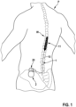
- An electrode device 1 shown in Fig. 1 and 2 in one embodiment is realised as a so-called paddle electrode and has an electrode body 10 and an electrode end 11 connected to the electrode body 10, to which electrode end there are attached a plurality of electrode elements for emitting stimulation energy in the region of the spine W of a patient P.
- the electrode device 1 is connected by a proximal end of the electrode body 10 to a terminal block 20 of a generator 2, via which stimulation energy may be delivered to the electrode device 1 and radiated via the electrode arrangement arranged at the electrode end 11 for stimulation of the spinal cord R in the region of the spine W.
- the electrode device 1 is implanted with the electrode end 11 in the epidural space E in the region of the spine W of the patient P in such a way that the electrode end 11 is located in the region of the spinal cord R and may thus introduce stimulation energy in a directed manner into the spinal cord R in order to cause nerve stimulation in the region of the spinal cord R.
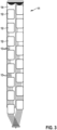
- the electrode device 1 is flattened in the region of the electrode end 11 and, as may be seen in Fig. 3 , carries a plurality of electrode elements 12 there, which may be arranged in two rows next to each other and are placed in relation to each other in such a way that stimulation energy may be fed in a directed manner, for example into the spinal cord R of a patient P.
- each electrode element 12 is connected to a supply line 13, and each electrode element 12 may be connected to the generator 2 via an associated supply line 13 and may thus be supplied with stimulation energy via the generator 2 to emit an electrical signal.
- the supply lines 13 are routed together as a cable harness in the electrode body 10 in an encapsulated manner to the generator 2.
- the electrode elements 12 are arranged on a support 14, but are exposed with a surface facing outwardly and may therefore come into contact with surrounding tissue when the electrode device 1 is implanted in a patient.
- the electrode elements 12 to the support 14 by heating the support 14 and/or the corresponding electrode element 12 so that the electrode element 12 in question may be pressed into the support 14 and may form an integrally bonded connection to the support 14.
- an electrode element 12 to be connected to the support 14 may be heated to a temperature at or near the melting temperature of the material of the support 14, which is made for example of a thermoplastic material, for example a polyurethane material, so that when the electrode element 12 is placed, the support 14 is melted in some regions and the electrode element 12 may thus be pressed into the support 14, so that an integral bond is created between the electrode element 12 and the support 14.
- a thermoplastic material for example a polyurethane material
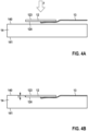
- the electrode element 12 is placed in a joining direction F against an upper side 140 of the support element 14 in such a way that - as may be seen in Fig. 4B - an upper side 123 of the electrode element 12 is flush with the upper side 140.
- the indentation depth T to which the electrode element 12 is pressed into the support 14, thus corresponds to the thickness of the electrode element 12.
- the upper side 123 of the electrode element 12 does not necessarily have to be flush with the upper side 140 of the support 14.
- the electrode element 14 may also be placed on the support 14 in such a way that the upper side 123 of the electrode element 12 for example protrudes relative to the upper side 140 of the support 14.
- the electrode element 12 may be placed on the support 14 with regard to the indentation depth T in such a way that a radiation characteristic for radiating electrical signals via the electrode element 12 is optimised.
- the electrode element 12 may be heated and brought to a temperature at or near the melting temperature of the material of the support 14, for example. Additionally or alternatively, the support 14 may also be heated. For example, to attach the electrode element 12 to the support 14, the electrode element 12 and/or the support 14 may be heated to a temperature higher than 100°C, for example higher than 150°C, preferably higher than 180°C, for example 190°C.
- a supply line 13 is connected to the electrode element 12 before the electrode element 12 is attached to the support 14.
- the supply line 13 is connected to an underside 124 of the electrode element 12 facing away from the upper side 123, so that when the electrode element 12 is placed on the support 14, the supply line 13 is located in some sections below the electrode element 12 and is pressed into the material of the support 14 together with the electrode element 12.
- the supply line 13 is thus embedded below the electrode element 12 in the support 14, so that the point of connection of the supply line 13 to the electrode element 12 is encased by the support 14 and the electrical connection between the supply line 13 and the electrode element 12 is thus secured.
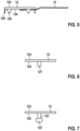
- the electrode element 12 forms a flat, for example rectangular or round surface element, which, with the upper side 123 in the attached position, points outwards and may emit electrical signals via the upper side 123 for stimulation, for example in the region of the spinal cord R of a patient P.
- the electrode element 12 may have fastening elements 120 in the form of tabs protruding from the underside 124, which serve to improve the mechanical connection of the electrode element 12 to the support 14.
- the fastening elements 120 come into form-fitting engagement with the support 14 and thus create a form fit between the electrode element 12 and the support 14, so that above this the hold of the electrode element 12 on the support 14 is improved.
- a plurality of fastening elements 120 can, for example, be formed along the outer peripheral edge of the electrode element 12 at a distance from each other on the electrode element 12.
- the fastening elements 120 can, for example, have a hook shape, for example in the form of barbs.
- openings may be formed on the fastening elements 120, in which openings the material of the support 14 may engage when the attachment is made, so that a form-fit hold of the electrode element 12 on the support 14 is further improved.
- a pin 121 is formed on the underside 124 of the electrode element 12, which pin penetrates the support 14 when the electrode element 12 is placed and thus becomes accessible on an underside 141 of the support 14 facing away from the upper side 140, so that a supply line 13 may be connected to the pin 121.
- a head 122 may be formed on the pin 121, which head forms an undercut, so that, via the pin 121, the mechanical hold of the electrode element 12 on the support 14 is also improved since a form fit with the support 14 is formed via the head 122, as shown in Fig. 8 .
- a supply line 13 may also be connected to the head 122, as shown in Fig. 8 .
- a supply line 13 may be connected after attaching the electrode element 12 to the support 14.
- the supply line 13 may be laid in the region of the underside 141 and thus on a rear side of the support 14, which faces away from the side of the electrode device 1 through which energy is radiated during operation. This may simplify the laying of the supply lines 13 to the different electrode elements 12.
- the support 14 may be surrounded for example by an encasement 15, for example by overmoulding the support 14, as shown in Fig. 9 .
- the encasement 15 may, for example, be made of a silicone material, and the support 14 may be completely surrounded by the material of the encasement 15, but the electrode elements 12 attached to the support 14 are exposed outwardly.
- the electrode device 1 may thus be enclosed and encapsulated in the region of the electrode end 11.
- the electrode device may be used for spinal nerve stimulation, but also for other stimulation, for example cardiac stimulation.
- One or more electrode elements may be arranged on the support, and - if a plurality of electrode elements are used - an arrangement of electrode elements may be created, by means of which a desired directional characteristic may be provided.
Landscapes
- Health & Medical Sciences (AREA)
- Animal Behavior & Ethology (AREA)
- Public Health (AREA)
- Engineering & Computer Science (AREA)
- Biomedical Technology (AREA)
- Nuclear Medicine, Radiotherapy & Molecular Imaging (AREA)
- Radiology & Medical Imaging (AREA)
- Life Sciences & Earth Sciences (AREA)
- General Health & Medical Sciences (AREA)
- Veterinary Medicine (AREA)
- Heart & Thoracic Surgery (AREA)
- Cardiology (AREA)
- Chemical & Material Sciences (AREA)
- Organic Chemistry (AREA)
- Neurology (AREA)
- Neurosurgery (AREA)
- Orthopedic Medicine & Surgery (AREA)
- Electrotherapy Devices (AREA)
Claims (15)
- Verfahren zur Herstellung einer implantierbaren Elektrodenvorrichtung (1), einen Elektrodenkörper (10), der mit einem Generator (2) verbindbar ist, und ein Elektrodenende (11), das distal mit dem Elektrodenkörper (10) verbunden ist, umfassend, wobei das Elektrodenende (11) einen elektrisch isolierenden Träger (14) und mindestens ein Elektrodenelement (12), das am Träger (14) befestigt ist, umfasst, wobei der Träger (14) mindestens eine flache Oberfläche umfasst, das Verfahren folgende Schritte umfassend: Bereitstellen eines elektrisch isolierenden Trägers (14), Bereitstellen des mindestens einen elektrisch leitenden Elektrodenelements (12) und Befestigen des mindestens einen Elektrodenelements (12) an der mindestens einen flachen Oberfläche des Trägers (14), wobei zum Befestigen des mindestens einen Elektrodenelements (12) an dem Träger (14) das mindestens eine Elektrodenelement (12) und/oder der Träger (14) erwärmt werden und das mindestens eine Elektrodenelement (12) gegen den Träger (14) gepresst wird.
- Verfahren nach Anspruch 1, wobei der Träger (14) aus einem Thermoplast hergestellt ist.
- Verfahren nach Anspruch 1 oder 2, wobei der Träger (14) aus einem Material hergestellt ist, das Polyurethan umfasst.
- Verfahren nach einem der Ansprüche 1 bis 3, wobei zum Befestigen des mindestens einen Elektrodenelements (12) an dem Träger (14) das mindestens eine Elektrodenelement (12) und/oder der Träger (14) auf eine Temperatur von über 100 °C, bevorzugt über 150 °C, besonders bevorzugt über 180°C erwärmt wird.
- Verfahren nach einem der vorstehenden Ansprüche, wobei das mindestens eine Elektrodenelement (12) an einer Oberseite (140) des Trägers (14) platziert wird.
- Verfahren nach Anspruch 5, wobei das mindestens eine Elektrodenelement (12) in der Art und Weise gegen den Träger (14) gepresst wird, dass eine Oberseite (123) des mindestens einen Elektrodenelements (12) bündig mit der Oberseite (140) des Trägers (14) ist.
- Verfahren nach einem der vorstehenden Ansprüche, wobei eine elektrische Zuleitung (13) an das mindestens eine Elektrodenelement (12) angeschlossen wird, bevor das mindestens eine Elektrodenelement (12) an dem Träger (14) befestigt wird.
- Verfahren nach Anspruch 7, wobei die Zuleitung (13), die an das mindestens eine Elektrodenelement (12) angeschlossen ist, zusammen mit dem mindestens einen Elektrodenelement (12) an dem Träger (14) befestigt wird.
- Verfahren nach einem der vorstehenden Ansprüche, wobei das mindestens eine Elektrodenelement (12) mindestens ein Befestigungselement (120) aufweist, das in den Träger (14) gepresst wird, wenn das mindestens eine Elektrodenelement (12) an dem Träger (14) befestigt wird.
- Verfahren nach einem der vorstehenden Ansprüche, wobei das mindestens eine Elektrodenelement (12) einen Stift (121) aufweist, der, wenn das mindestens eine Elektrodenelement (12) an dem Träger (14) befestigt wird, auf die Art und Weise in den Träger (14) gepresst wird, dass der Stift (121) eine Unterseite (141) durchdringt, die von einer Oberseite (140) des Trägers (14) weg weist.
- Verfahren nach Anspruch 10, wobei nach dem Befestigen des mindestens einen Elektrodenelements (12) an dem Träger (14) eine elektrische Zuleitung (13) an den Stift (121) angeschlossen wird.
- Verfahren nach einem der vorstehenden Ansprüche, wobei der Träger (14) nach dem Aufbringen des mindestens einen Elektrodenelements (12) zumindest teilweise von einer Ummantelung (15) umgeben wird.
- Verfahren nach Anspruch 12, wobei die Ummantelung (15) aus einem SilikonMaterial besteht.
- Verfahren nach einem der vorstehenden Ansprüche, wobei eine Vielzahl von Elektrodenelementen (12) an dem Träger (14) befestigt werden.
- Implantierbare Elektrodenvorrichtung (1), einen Elektrodenkörper (10), der mit einem Generator (2) verbindbar ist, und ein Elektrodenende (11), das distal mit dem Elektrodenkörper (10) verbunden ist, umfassend, wobei das Elektrodenende (11) einen Träger (14) mit mindestens einer flachen Oberfläche und eine Vielzahl von Elektrodenelementen (12), die an der mindestens einen flachen Oberfläche des Trägers (14) befestigt sind, umfasst, wobei die Elektrodenelemente (12) durch das Verfahren nach einem der Ansprüche 1 bis 14 an dem Träger (14) befestigt werden.
Applications Claiming Priority (2)
| Application Number | Priority Date | Filing Date | Title |
|---|---|---|---|
| EP20150782 | 2020-01-08 | ||
| PCT/EP2020/086462 WO2021139984A1 (en) | 2020-01-08 | 2020-12-16 | Method for producing an implantable electrode device |
Publications (2)
| Publication Number | Publication Date |
|---|---|
| EP4087642A1 EP4087642A1 (de) | 2022-11-16 |
| EP4087642B1 true EP4087642B1 (de) | 2025-06-11 |
Family
ID=69156217
Family Applications (1)
| Application Number | Title | Priority Date | Filing Date |
|---|---|---|---|
| EP20824256.0A Active EP4087642B1 (de) | 2020-01-08 | 2020-12-16 | Verfahren zur herstellung einer implantierbaren elektrodenvorrichtung |
Country Status (5)
| Country | Link |
|---|---|
| US (1) | US20230032407A1 (de) |
| EP (1) | EP4087642B1 (de) |
| JP (2) | JP2023510484A (de) |
| CN (1) | CN114845769A (de) |
| WO (1) | WO2021139984A1 (de) |
Family Cites Families (9)
| Publication number | Priority date | Publication date | Assignee | Title |
|---|---|---|---|---|
| US5524337A (en) * | 1994-09-21 | 1996-06-11 | Ep Technologies, Inc. | Method of securing ring electrodes onto catheter |
| JP2000502922A (ja) * | 1996-01-31 | 2000-03-14 | コクリヤ リミテッド | 埋植型電極のための薄膜製作技術 |
| JP3717368B2 (ja) * | 2000-04-19 | 2005-11-16 | 積水化成品工業株式会社 | 電極 |
| US6895283B2 (en) * | 2000-08-10 | 2005-05-17 | Advanced Neuromodulation Systems, Inc. | Stimulation/sensing lead adapted for percutaneous insertion |
| US7738966B2 (en) | 2006-08-21 | 2010-06-15 | Medtronic, Inc. | Features for routing conductors in medical electrical lead electrode assemblies |
| US20110307042A1 (en) * | 2009-02-26 | 2011-12-15 | Opm Medical Acquisition, Llc | Electrode arrays based on polyetherketoneketone |
| US9289600B2 (en) * | 2012-12-03 | 2016-03-22 | Boston Scientific Neuromodulation Corporation | Electrical stimulation paddle leads and methods of making and using |
| JP2015181777A (ja) * | 2014-03-25 | 2015-10-22 | オリンパス株式会社 | 電気刺激電極組立体の製造方法および電気刺激電極組立体 |
| KR102318044B1 (ko) * | 2016-02-29 | 2021-10-28 | 한국전자통신연구원 | 전극체 및 전극체 제조 방법 |
-
2020
- 2020-12-16 EP EP20824256.0A patent/EP4087642B1/de active Active
- 2020-12-16 WO PCT/EP2020/086462 patent/WO2021139984A1/en not_active Ceased
- 2020-12-16 JP JP2022533357A patent/JP2023510484A/ja active Pending
- 2020-12-16 CN CN202080090292.6A patent/CN114845769A/zh active Pending
- 2020-12-16 US US17/789,582 patent/US20230032407A1/en active Pending
-
2025
- 2025-07-17 JP JP2025120904A patent/JP2025143526A/ja active Pending
Also Published As
| Publication number | Publication date |
|---|---|
| WO2021139984A1 (en) | 2021-07-15 |
| US20230032407A1 (en) | 2023-02-02 |
| JP2023510484A (ja) | 2023-03-14 |
| CN114845769A (zh) | 2022-08-02 |
| JP2025143526A (ja) | 2025-10-01 |
| EP4087642A1 (de) | 2022-11-16 |
Similar Documents
| Publication | Publication Date | Title |
|---|---|---|
| US10420931B2 (en) | Field steerable electrical stimulation paddle, lead system, and medical device incorporating the same | |
| US8515557B2 (en) | Electrode array for a cochlear implant | |
| US20050027338A1 (en) | Stretchable lead body, method of manufacture, and system | |
| EP2326386B1 (de) | Elektrodenreihe und herstellungsverfahren dafür | |
| AU2014315426B2 (en) | Leads with electrodes disposed in mesh material and methods and systems using the leads | |
| CN112004573B (zh) | 用于电刺激的电极装置,其电极体和制造电极装置的方法 | |
| JP2009532103A (ja) | カフ・リードのための電極コンタクト構成 | |
| US11129986B2 (en) | Implantable stimulator with a conformable foil like electrode array | |
| JP2021502215A (ja) | 電気刺激システムのための扁平制御モジュールを製造かつ使用するためのシステム及び方法 | |
| EP4087642B1 (de) | Verfahren zur herstellung einer implantierbaren elektrodenvorrichtung | |
| CN106310514B (zh) | 馈通连接器 | |
| US8460562B2 (en) | Cochlear implant assembly | |
| EP3965871B1 (de) | Verfahren zur verringerung von blitzen auf elektroden und elektrodenbaugruppe | |
| JP2000502922A (ja) | 埋植型電極のための薄膜製作技術 | |
| EP4037756B1 (de) | Medizinische elektrodenvorrichtung zur implantation in einen patienten | |
| US20240371546A1 (en) | Method for Fabricating a Medical Electrode Device | |
| US20220176102A1 (en) | Insulated electrode for delivering tumor treating electromagnetic fields | |
| US20250018178A1 (en) | Medical Electrode Device Comprising at Least One Contact Element | |
| JP5265209B2 (ja) | 視覚再生補助装置 | |
| US11077303B2 (en) | Implantable probe for electrical stimulation and/or for detection of electrical potentials on an organ |
Legal Events
| Date | Code | Title | Description |
|---|---|---|---|
| STAA | Information on the status of an ep patent application or granted ep patent |
Free format text: STATUS: UNKNOWN |
|
| STAA | Information on the status of an ep patent application or granted ep patent |
Free format text: STATUS: THE INTERNATIONAL PUBLICATION HAS BEEN MADE |
|
| PUAI | Public reference made under article 153(3) epc to a published international application that has entered the european phase |
Free format text: ORIGINAL CODE: 0009012 |
|
| STAA | Information on the status of an ep patent application or granted ep patent |
Free format text: STATUS: REQUEST FOR EXAMINATION WAS MADE |
|
| 17P | Request for examination filed |
Effective date: 20220608 |
|
| AK | Designated contracting states |
Kind code of ref document: A1 Designated state(s): AL AT BE BG CH CY CZ DE DK EE ES FI FR GB GR HR HU IE IS IT LI LT LU LV MC MK MT NL NO PL PT RO RS SE SI SK SM TR |
|
| DAV | Request for validation of the european patent (deleted) | ||
| DAX | Request for extension of the european patent (deleted) | ||
| GRAP | Despatch of communication of intention to grant a patent |
Free format text: ORIGINAL CODE: EPIDOSNIGR1 |
|
| STAA | Information on the status of an ep patent application or granted ep patent |
Free format text: STATUS: GRANT OF PATENT IS INTENDED |
|
| INTG | Intention to grant announced |
Effective date: 20250214 |
|
| GRAS | Grant fee paid |
Free format text: ORIGINAL CODE: EPIDOSNIGR3 |
|
| GRAA | (expected) grant |
Free format text: ORIGINAL CODE: 0009210 |
|
| STAA | Information on the status of an ep patent application or granted ep patent |
Free format text: STATUS: THE PATENT HAS BEEN GRANTED |
|
| AK | Designated contracting states |
Kind code of ref document: B1 Designated state(s): AL AT BE BG CH CY CZ DE DK EE ES FI FR GB GR HR HU IE IS IT LI LT LU LV MC MK MT NL NO PL PT RO RS SE SI SK SM TR |
|
| REG | Reference to a national code |
Ref country code: GB Ref legal event code: FG4D |
|
| REG | Reference to a national code |
Ref country code: CH Ref legal event code: EP |
|
| REG | Reference to a national code |
Ref country code: IE Ref legal event code: FG4D |
|
| REG | Reference to a national code |
Ref country code: DE Ref legal event code: R096 Ref document number: 602020052697 Country of ref document: DE |
|
| P01 | Opt-out of the competence of the unified patent court (upc) registered |
Free format text: CASE NUMBER: APP_30669/2025 Effective date: 20250626 |
|
| PG25 | Lapsed in a contracting state [announced via postgrant information from national office to epo] |
Ref country code: ES Free format text: LAPSE BECAUSE OF FAILURE TO SUBMIT A TRANSLATION OF THE DESCRIPTION OR TO PAY THE FEE WITHIN THE PRESCRIBED TIME-LIMIT Effective date: 20250611 Ref country code: FI Free format text: LAPSE BECAUSE OF FAILURE TO SUBMIT A TRANSLATION OF THE DESCRIPTION OR TO PAY THE FEE WITHIN THE PRESCRIBED TIME-LIMIT Effective date: 20250611 |
|
| REG | Reference to a national code |
Ref country code: LT Ref legal event code: MG9D |
|
| PG25 | Lapsed in a contracting state [announced via postgrant information from national office to epo] |
Ref country code: NO Free format text: LAPSE BECAUSE OF FAILURE TO SUBMIT A TRANSLATION OF THE DESCRIPTION OR TO PAY THE FEE WITHIN THE PRESCRIBED TIME-LIMIT Effective date: 20250911 Ref country code: GR Free format text: LAPSE BECAUSE OF FAILURE TO SUBMIT A TRANSLATION OF THE DESCRIPTION OR TO PAY THE FEE WITHIN THE PRESCRIBED TIME-LIMIT Effective date: 20250912 |
|
| REG | Reference to a national code |
Ref country code: NL Ref legal event code: MP Effective date: 20250611 |
|
| PG25 | Lapsed in a contracting state [announced via postgrant information from national office to epo] |
Ref country code: BG Free format text: LAPSE BECAUSE OF FAILURE TO SUBMIT A TRANSLATION OF THE DESCRIPTION OR TO PAY THE FEE WITHIN THE PRESCRIBED TIME-LIMIT Effective date: 20250611 |
|
| PG25 | Lapsed in a contracting state [announced via postgrant information from national office to epo] |
Ref country code: HR Free format text: LAPSE BECAUSE OF FAILURE TO SUBMIT A TRANSLATION OF THE DESCRIPTION OR TO PAY THE FEE WITHIN THE PRESCRIBED TIME-LIMIT Effective date: 20250611 |
|
| PG25 | Lapsed in a contracting state [announced via postgrant information from national office to epo] |
Ref country code: RS Free format text: LAPSE BECAUSE OF FAILURE TO SUBMIT A TRANSLATION OF THE DESCRIPTION OR TO PAY THE FEE WITHIN THE PRESCRIBED TIME-LIMIT Effective date: 20250911 |
|
| PG25 | Lapsed in a contracting state [announced via postgrant information from national office to epo] |
Ref country code: LV Free format text: LAPSE BECAUSE OF FAILURE TO SUBMIT A TRANSLATION OF THE DESCRIPTION OR TO PAY THE FEE WITHIN THE PRESCRIBED TIME-LIMIT Effective date: 20250611 |
|
| PG25 | Lapsed in a contracting state [announced via postgrant information from national office to epo] |
Ref country code: NL Free format text: LAPSE BECAUSE OF FAILURE TO SUBMIT A TRANSLATION OF THE DESCRIPTION OR TO PAY THE FEE WITHIN THE PRESCRIBED TIME-LIMIT Effective date: 20250611 |
|
| PG25 | Lapsed in a contracting state [announced via postgrant information from national office to epo] |
Ref country code: PT Free format text: LAPSE BECAUSE OF FAILURE TO SUBMIT A TRANSLATION OF THE DESCRIPTION OR TO PAY THE FEE WITHIN THE PRESCRIBED TIME-LIMIT Effective date: 20251013 |
|
| REG | Reference to a national code |
Ref country code: AT Ref legal event code: MK05 Ref document number: 1801895 Country of ref document: AT Kind code of ref document: T Effective date: 20250611 |
|
| PG25 | Lapsed in a contracting state [announced via postgrant information from national office to epo] |
Ref country code: IS Free format text: LAPSE BECAUSE OF FAILURE TO SUBMIT A TRANSLATION OF THE DESCRIPTION OR TO PAY THE FEE WITHIN THE PRESCRIBED TIME-LIMIT Effective date: 20251011 |
|
| PGFP | Annual fee paid to national office [announced via postgrant information from national office to epo] |
Ref country code: GB Payment date: 20251218 Year of fee payment: 6 |
|
| PG25 | Lapsed in a contracting state [announced via postgrant information from national office to epo] |
Ref country code: AT Free format text: LAPSE BECAUSE OF FAILURE TO SUBMIT A TRANSLATION OF THE DESCRIPTION OR TO PAY THE FEE WITHIN THE PRESCRIBED TIME-LIMIT Effective date: 20250611 Ref country code: SM Free format text: LAPSE BECAUSE OF FAILURE TO SUBMIT A TRANSLATION OF THE DESCRIPTION OR TO PAY THE FEE WITHIN THE PRESCRIBED TIME-LIMIT Effective date: 20250611 |
|
| PGFP | Annual fee paid to national office [announced via postgrant information from national office to epo] |
Ref country code: FR Payment date: 20251218 Year of fee payment: 6 |
|
| PG25 | Lapsed in a contracting state [announced via postgrant information from national office to epo] |
Ref country code: CZ Free format text: LAPSE BECAUSE OF FAILURE TO SUBMIT A TRANSLATION OF THE DESCRIPTION OR TO PAY THE FEE WITHIN THE PRESCRIBED TIME-LIMIT Effective date: 20250611 |
|
| PG25 | Lapsed in a contracting state [announced via postgrant information from national office to epo] |
Ref country code: PL Free format text: LAPSE BECAUSE OF FAILURE TO SUBMIT A TRANSLATION OF THE DESCRIPTION OR TO PAY THE FEE WITHIN THE PRESCRIBED TIME-LIMIT Effective date: 20250611 |
|
| PG25 | Lapsed in a contracting state [announced via postgrant information from national office to epo] |
Ref country code: EE Free format text: LAPSE BECAUSE OF FAILURE TO SUBMIT A TRANSLATION OF THE DESCRIPTION OR TO PAY THE FEE WITHIN THE PRESCRIBED TIME-LIMIT Effective date: 20250611 |
|
| PG25 | Lapsed in a contracting state [announced via postgrant information from national office to epo] |
Ref country code: SK Free format text: LAPSE BECAUSE OF FAILURE TO SUBMIT A TRANSLATION OF THE DESCRIPTION OR TO PAY THE FEE WITHIN THE PRESCRIBED TIME-LIMIT Effective date: 20250611 |
|
| PG25 | Lapsed in a contracting state [announced via postgrant information from national office to epo] |
Ref country code: RO Free format text: LAPSE BECAUSE OF FAILURE TO SUBMIT A TRANSLATION OF THE DESCRIPTION OR TO PAY THE FEE WITHIN THE PRESCRIBED TIME-LIMIT Effective date: 20250611 |