EP4087478B1 - Sondenspitze für medizinprodukt - Google Patents
Sondenspitze für medizinprodukt Download PDFInfo
- Publication number
- EP4087478B1 EP4087478B1 EP21738817.2A EP21738817A EP4087478B1 EP 4087478 B1 EP4087478 B1 EP 4087478B1 EP 21738817 A EP21738817 A EP 21738817A EP 4087478 B1 EP4087478 B1 EP 4087478B1
- Authority
- EP
- European Patent Office
- Prior art keywords
- pcb
- housing
- optical fiber
- system unit
- probe tip
- Prior art date
- Legal status (The legal status is an assumption and is not a legal conclusion. Google has not performed a legal analysis and makes no representation as to the accuracy of the status listed.)
- Active
Links
Images









Classifications
-
- A—HUMAN NECESSITIES
- A61—MEDICAL OR VETERINARY SCIENCE; HYGIENE
- A61B—DIAGNOSIS; SURGERY; IDENTIFICATION
- A61B5/00—Measuring for diagnostic purposes; Identification of persons
- A61B5/145—Measuring characteristics of blood in vivo, e.g. gas concentration or pH-value ; Measuring characteristics of body fluids or tissues, e.g. interstitial fluid or cerebral tissue
- A61B5/1455—Measuring characteristics of blood in vivo, e.g. gas concentration or pH-value ; Measuring characteristics of body fluids or tissues, e.g. interstitial fluid or cerebral tissue using optical sensors, e.g. spectral photometrical oximeters
- A61B5/14551—Measuring characteristics of blood in vivo, e.g. gas concentration or pH-value ; Measuring characteristics of body fluids or tissues, e.g. interstitial fluid or cerebral tissue using optical sensors, e.g. spectral photometrical oximeters for measuring blood gases
- A61B5/14552—Details of sensors specially adapted therefor
-
- A—HUMAN NECESSITIES
- A61—MEDICAL OR VETERINARY SCIENCE; HYGIENE
- A61B—DIAGNOSIS; SURGERY; IDENTIFICATION
- A61B2503/00—Evaluating a particular growth phase or type of persons or animals
- A61B2503/10—Athletes
-
- A—HUMAN NECESSITIES
- A61—MEDICAL OR VETERINARY SCIENCE; HYGIENE
- A61B—DIAGNOSIS; SURGERY; IDENTIFICATION
- A61B2503/00—Evaluating a particular growth phase or type of persons or animals
- A61B2503/40—Animals
-
- A—HUMAN NECESSITIES
- A61—MEDICAL OR VETERINARY SCIENCE; HYGIENE
- A61B—DIAGNOSIS; SURGERY; IDENTIFICATION
- A61B2560/00—Constructional details of operational features of apparatus; Accessories for medical measuring apparatus
- A61B2560/02—Operational features
- A61B2560/0204—Operational features of power management
- A61B2560/0214—Operational features of power management of power generation or supply
-
- A—HUMAN NECESSITIES
- A61—MEDICAL OR VETERINARY SCIENCE; HYGIENE
- A61B—DIAGNOSIS; SURGERY; IDENTIFICATION
- A61B2560/00—Constructional details of operational features of apparatus; Accessories for medical measuring apparatus
- A61B2560/04—Constructional details of apparatus
- A61B2560/0406—Constructional details of apparatus specially shaped apparatus housings
- A61B2560/0418—Pen-shaped housings
-
- A—HUMAN NECESSITIES
- A61—MEDICAL OR VETERINARY SCIENCE; HYGIENE
- A61B—DIAGNOSIS; SURGERY; IDENTIFICATION
- A61B2560/00—Constructional details of operational features of apparatus; Accessories for medical measuring apparatus
- A61B2560/04—Constructional details of apparatus
- A61B2560/0431—Portable apparatus, e.g. comprising a handle or case
-
- A—HUMAN NECESSITIES
- A61—MEDICAL OR VETERINARY SCIENCE; HYGIENE
- A61B—DIAGNOSIS; SURGERY; IDENTIFICATION
- A61B2562/00—Details of sensors; Constructional details of sensor housings or probes; Accessories for sensors
- A61B2562/02—Details of sensors specially adapted for in-vivo measurements
- A61B2562/0219—Inertial sensors, e.g. accelerometers, gyroscopes, tilt switches
-
- A—HUMAN NECESSITIES
- A61—MEDICAL OR VETERINARY SCIENCE; HYGIENE
- A61B—DIAGNOSIS; SURGERY; IDENTIFICATION
- A61B2562/00—Details of sensors; Constructional details of sensor housings or probes; Accessories for sensors
- A61B2562/02—Details of sensors specially adapted for in-vivo measurements
- A61B2562/0233—Special features of optical sensors or probes classified in A61B5/00
-
- A—HUMAN NECESSITIES
- A61—MEDICAL OR VETERINARY SCIENCE; HYGIENE
- A61B—DIAGNOSIS; SURGERY; IDENTIFICATION
- A61B2562/00—Details of sensors; Constructional details of sensor housings or probes; Accessories for sensors
- A61B2562/02—Details of sensors specially adapted for in-vivo measurements
- A61B2562/0271—Thermal or temperature sensors
-
- A—HUMAN NECESSITIES
- A61—MEDICAL OR VETERINARY SCIENCE; HYGIENE
- A61B—DIAGNOSIS; SURGERY; IDENTIFICATION
- A61B2562/00—Details of sensors; Constructional details of sensor housings or probes; Accessories for sensors
- A61B2562/12—Manufacturing methods specially adapted for producing sensors for in-vivo measurements
-
- A—HUMAN NECESSITIES
- A61—MEDICAL OR VETERINARY SCIENCE; HYGIENE
- A61B—DIAGNOSIS; SURGERY; IDENTIFICATION
- A61B2562/00—Details of sensors; Constructional details of sensor housings or probes; Accessories for sensors
- A61B2562/16—Details of sensor housings or probes; Details of structural supports for sensors
- A61B2562/166—Details of sensor housings or probes; Details of structural supports for sensors the sensor is mounted on a specially adapted printed circuit board
-
- A—HUMAN NECESSITIES
- A61—MEDICAL OR VETERINARY SCIENCE; HYGIENE
- A61B—DIAGNOSIS; SURGERY; IDENTIFICATION
- A61B2562/00—Details of sensors; Constructional details of sensor housings or probes; Accessories for sensors
- A61B2562/18—Shielding or protection of sensors from environmental influences, e.g. protection from mechanical damage
Definitions
- Oximeters are medical devices used to measure the oxygen saturation of tissue in humans and living things for various purposes.
- oximeters are used for medical and diagnostic purposes in hospitals and other medical facilities (e.g., operating rooms for surgery, recovery room for patient monitoring, or ambulance or other mobile monitoring for, e.g., hypoxia); sports and athletic purposes at a sports arena (e.g., professional athlete monitoring); personal or at-home monitoring of individuals (e.g., general health monitoring, or person training for a marathon); and veterinary purposes (e.g., animal monitoring).
- hospitals and other medical facilities e.g., operating rooms for surgery, recovery room for patient monitoring, or ambulance or other mobile monitoring for, e.g., hypoxia
- sports and athletic purposes at a sports arena e.g., professional athlete monitoring
- personal or at-home monitoring of individuals e.g., general health monitoring, or person training for a marathon
- veterinary purposes e.g., animal monitoring.
- Human tissue includes a variety of light-absorbing molecules.
- Such chromophores include oxygenated hemoglobin, deoxygenated hemoglobin, melanin, water, lipid, and cytochrome.
- Oxygenated and deoxygenated hemoglobins are the dominant chromophores in tissue for much of the visible and near-infrared spectral range.
- Light absorption differs significantly for oxygenated and deoxygenated hemoglobins at certain wavelengths of light.
- Tissue oximeters can measure oxygen levels in human tissue by exploiting these light-absorption differences.
- Prior art tissue oximeters are disclosed in WO2014/026200A1 and WO2013/166461A1 .
- the probe tip includes a first printed circuit board (PCB), a second PCB, and a first optical fiber coupled to the first and second PCBs.
- the first PCB is positioned closer to the proximal end of the housing than the second PCB.
- the second PCB is positioned closer to the distal end of the housing than the first PCB.
- a first surface of the first PCB faces the distal end of the housing, a second surface of the second PCB faces the proximal end of the housing, an angle between the first and second surfaces is nonzero and is less than ninety degrees (e.g., from about 65 degrees to about 70 degrees).
- a first end portion of the first optical fiber located at the first PCB is approximately transverse to the first surface of the first PCB.
- a second end portion of the first optical fiber located at the second PCB is approximately transverse to the second surface of the second PCB.
- a portion of the first optical fiber between the first and second end portions of the first optical fiber is curved.
- Spectroscopy has been used for noninvasive measurements of various physiological properties in animal and human subjects. Visible (e.g., red light, green light, or both) and near-infrared spectroscopy is often utilized because physiological tissues have relatively low scattering in these spectral ranges.
- Human tissues include numerous light-absorbing chromophores, such as oxygenated hemoglobin, deoxygenated hemoglobin, melanin, water, lipid, and cytochrome.
- the hemoglobins are the dominant chromophores in tissue for much of the visible and near-infrared spectral range and via light absorption, contribute to the color of human tissues.
- oxygenated and deoxygenated hemoglobins have significantly different absorption features. Accordingly, visible and near-infrared spectroscopy has been applied to exploit these different absorption features for measuring oxygen levels in physiological media, such as tissue hemoglobin oxygen saturation (sometimes referred to as oxygen saturation) and total hemoglobin concentrations.
- TRS time-resolved spectroscopy
- PMS phase modulation spectroscopy
- CWS continuous wave spectroscopy
- wavelengths of light can then be used with SRS to determine oxygenated and deoxygenated hemoglobin concentrations, and therefore, oxygen saturation within the volume of the tissue probed.
- the wavelengths of the light source or light sources and the relative positions of the light source(s) with respect to a single detector or multiple ones of the detectors allow tissue oximetry measurements to be made for a predetermined tissue depth.
- one or more of the light sources and one or more of the detector source may emit and detect light so that oximetry measurements may be made for one or more predetermined tissue depths.
- Oximetry probes and sheaths of the present invention are directed toward improved sanitation, sterilization, or both.
- the signal is received at the probe tip.
- This received signal is received and analyzed by the sensor probe electronics.
- the sensor probe electronics determine various parameters of the tissue, such as an oxygen saturation level, a total hemoglobin concentration, an oxygenated hemoglobin concentration, a deoxygenated hemoglobin concentration, a blood flow, a pulse, a signal level of light reflected from the tissue, melanin concentration of tissue, or other tissue parameters.
- an oxygen saturation level a total hemoglobin concentration
- an oxygenated hemoglobin concentration a deoxygenated hemoglobin concentration
- a blood flow a pulse
- a signal level of light reflected from the tissue melanin concentration of tissue, or other tissue parameters.
- One or any combination of these parameters can be displayed on a display screen of the system unit.
- Figure 2 shows system unit 101 housed in a sheath 205.
- the sheath includes a lid 215 and a body 220, which may be sealed to the lid via a seal 210.
- the lib may be separable from the body or may be connected to the body, such as via a hinge.
- the hinge may allow the lid to rotate to seal the lid to the body.
- the sheath may be a disposable sheath or a sheath that is reusable.
- the system unit and sheath may travel with a patient from surgery (e.g., use) to post-surgery (e.g., reuse) for tissue monitoring.
- the system unit With the lid opened, the system unit may be inserted into the sheath, and thereafter the lid may be sealed to the body to house and seal the system unit in the sheath.
- the system unit may then be used to make tissue parameter measurements in the sealed environment provided by the sheath.
- the sheath can protect the system unit from contacting elements that the sheath contacts, such as tissue, tissue fluid, biological agents (e.g., bacteria, viruses, and prions), debris, and other contaminants.
- tissue tissue fluid
- biological agents e.g., bacteria, viruses, and prions
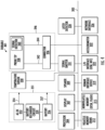
- FIG. 3 shows a block diagram of system unit 301, in an implementation.
- the system unit includes a processor 304, display 307, speaker 309, signal emitter 331, signal detector 333, volatile memory 312, nonvolatile memory 315, human interface device (HID) 319, input-output (I/O) interface 322, network interface 326, latch detector 328, temperature sensor 330, and accelerometer 332.
- These components are housed within housing 103.
- Different implementations of the system may include any number of the components described, in any combination or configuration, and may also include other components not shown.
- system unit 301 includes a sensor probe 346.
- the sensor probe includes a probe tip 338 and a connector 336.
- the probe tip is connected to the connector via a first communication link 342 and a second communication link 344.
- First communication link 342 may include an electrical wire, a set of electrical wires (e.g., a ribbon cable), a waveguide (e.g., a fiber optic cable), a number of waveguides (e.g., a number of fiber optic cables), a wireless communication link, or any combination of these types of links.
- the connector may also have a second keying feature that provides an indication to the system unit a type of probe (e.g., a probe from many different types of probes) that is attached.
- the system unit may be adapted to make measurements for a number of different types of probes.
- the system uses the second keying feature to determine the type of probe that is connected to the system unit. Then the system unit can perform the appropriate functions, use the appropriate algorithms, or otherwise make adjustments in its operation for the specific probe type.
- signal emitter 331 is an emitter that emits electrical signals to one or more light sources, which may emit light based on the received electrical signals.
- the signal emitter includes one or more light sources and electrical signal emitters that are connected to the light sources.
- the accelerometer may detect movements (e.g., gestures) of the system unit where the system unit may be moved by a user. Movements may include a left movement, right movement, forward movement, back movement, up movement, down movement, one or more rotational movements (e.g., about one or more axes of rotation, such as the x-axis, y-axis, z-axis, or another axis), any combinations of these movements, or other movements.
- movements e.g., gestures
- Movements may include a left movement, right movement, forward movement, back movement, up movement, down movement, one or more rotational movements (e.g., about one or more axes of rotation, such as the x-axis, y-axis, z-axis, or another axis), any combinations of these movements, or other movements.
- information for a left movement or a right movement detected by the accelerometer and transmitted to the processor may be used by the processor to control the system unit.
- a left or right movement of the system unit may be used by the processor to change menu items displayed on the display.
- the processor may use the information for a left movement to scroll menu items on the display to the left (e.g., scroll a first menu item left and off of the display to display a second menu item on the display).
- the processor may use the information for a right movement of the system unit to scroll menu items to the right (e.g., scroll a first menu item right and off of the display, and display a second menu item on the display).
- the HID and processor may be adapted to detect and use various movements to activate a menu item that is displayed on the display. For example, information for an upward movement or a downward movement may be detected and used to activate a menu item that is displayed on the display. For example, if a user is prepared to take an oximeter measurement and a menu option is displayed for taking an oximeter measurement, a quick downward movement of the system unit may start a measurement when the probe tip is placed in contact with tissue
- the HID may include one or more accelerometers to detect motion in various directions (e.g., linear, rotational, or both).
- the accelerometers can include one or more capacitive micro-electro-mechanical system (MEMS) devices, one or more piezoresistive devices, one or more piezoelectric devices, or any combination of these devices.
- MEMS micro-electro-mechanical system
- accelerometer 332 is adapted to detect relatively high G-force accelerations associated with a shock that the system unit experiences.
- the shock may be from bumping the system into something, dropping the system unit (e.g., dropping the system unit on a table or the floor), or other shock events.
- the processor can take a number of actions. For example, the processor can shut down the system unit.
- the processor can display one or more messages on the display. The messages may indicate that the system unit should be recalibrated. The message may indicate that contact between the system unit and the sheath should be checked.
- the accelerometer may include one or more capacitive micro-electro-mechanical system (MEMS) devices, one or more piezoresistive devices, one or more piezoelectric devices, or any combination of these devices.
- MEMS micro-electro-mechanical system
- the latch detector 328 is adapted to detect whether a latch of the sheath is latched or unlatched. If the latch is latched, then the system unit is housed and enclosed in the sheath. In this configuration, with the system unit housed and enclosed in the sheath, the system unit may not be contaminated by material contacting the outside surface of the sheath. If the latch is unlatched and the system unit is in the sheath, then the system unit might be contaminated with material contacting the outside surface of the sheath.
- At least a first portion of the latch is metal.
- Other portions of the latch may be metal or other material, such as a plastic material.
- the first portion of the latch is a first distance from the latch detector when the latch is latched and is a second distance from the latch detector when the latch is unlatched. The first distance is less than the second distance.
- the latch detector is a capacitive detector that can capacitively couple to the latch.
- the capacitive detector can detect the latch in the latched position at a first distance from the capacitive detector and moving away from the latched position and the first distance.
- a binary, machine-executable version, of the software of the present invention may be stored or reside in RAM or cache memory, or on a mass storage device.
- Source code of the software of the present invention may also be stored or reside on a mass storage device (e.g., hard disk, magnetic disk, tape, or CD-ROM).
- code of the invention may be transmitted via wires, radio waves, or through a network such as the Internet.
- Firmware may be stored in a ROM of the system.
- An operating system for the system may be one of the Microsoft Windows ® family of operating systems (e.g., Windows XP, Windows XP x64 Edition, Windows Vista, Windows CE, Windows 7, Windows 8, Windows 10, Windows Mobile), Linux, HP-UX, UNIX, Solaris, Mac OS X, Alpha OS, AIX, IRIX32, or IRIX64.
- Microsoft Windows is a trademark of Microsoft Corporation.
- Other operating systems may be used, including custom and proprietary operating systems.
- FIG. 4 shows a block diagram of system unit 401, in an implementation.
- System unit 401 is similar to system unit 301 but differs in that the signal detector 344 is located in probe tip 346.
- a wire or set of wires may connect the signal detector to the bus and processor.
- a ribbon cable that is connected to the signal detector may also be connected to a connector or socket mounted on a PCB that the processor and other circuits are mounted on.
- the signal detector may be located at a probe face of the probe tip.
- the signal emitter may be optically located behind the probe face of the probe tip.
- FIG. 5 shows a block diagram of system unit 501, in an implementation.
- System unit 501 is similar to system units 301 and 401 but differs in that the signal emitter 331 and the signal detector 344 are located in probe tip 346.
- a wire or wires e.g., one or more ribbon cables
- a first ribbon cable may connect the signal emitter to the bus and processor and a second ribbon cable may connect the signal detector to the bus and processor.
- the first ribbon cable that is connected to the signal emitter may also be connected to a connector or socket mounted on a PCB that the processor and other circuits are mounted on, and the second ribbon cable that is connected to the signal detector may also be connected to a connector or socket mounted on the PCB.
- the signal detector may be located at a probe face of the probe tip.
- the signal emitter may be optically located behind the probe face of the probe tip.
- connector 336 includes a locking feature, such as an insert connector that inserts into a connecting port and then twists or screws to lock. If so, the connector is more securely held to the system unit and it will need to be unlocked before it can be removed. This will help prevent accidental removal of the probe.
- a locking feature such as an insert connector that inserts into a connecting port and then twists or screws to lock. If so, the connector is more securely held to the system unit and it will need to be unlocked before it can be removed. This will help prevent accidental removal of the probe.
- the battery cells may be disposable battery cells, such as alkaline battery cells, or rechargeable battery cells, such as nickel metal hydride, lithium battery cells (e.g., Li/FeS2 size AA, AAA, N, CR123, 18650, or others), lithium polymer, or other types of cells.
- the power back may include four battery cells that are AA size cells that output 1.5 volts.
- the four batteries may be in series to output 6 volts, or may be in series and parallel to output 3 volts.
- Allowing the system unit to operate with known (e.g., authorized) power blocks the system unit is assured that the power provided by the power block is within the operating specifications of the system unit. Therefore, the circuits, signal emitters, signal detectors, and other elements of the system unit will operate within predetermined parameters and will not operate outside of the predetermined parameters. Operating the system unit according to predetermined parameters, facilitates the system unit making accurate and reliable oximetry measurements.
- nonvolatile memory 315 stores one or more identifiers for one or more power blocks that may operate with the system unit.
- the processor may compare the identifier for the power pack that has been decrypted to the one or more identifiers retrieved from the nonvolatile memory to determine whether the power block will be allowed to operate with the system unit. If the power block is not authorized for use with the system unit, the processor may cause a message to be displayed on the display that indicates that the power block is not authorized for use with the system unit. If the power block is authorized to operate with the system unit, then the system unit may operate to make oximetry measurements without displaying information on the display about the authenticity or the inauthenticity of the power block.
- the processor of the system unit may query the power block's memory to retrieve any system identifier that may be stored in the power block's memory.
- the system unit will not operate with the power block.
- the implementation attempts to ensure that a power block is fully charged and can be used for the duration of a medical procedure (e.g., a surgery) without the power block running out of stored energy.
- Ensuring that a power block is unused prior to using the power block during a medical procedure provides that the power block will not run out of power during the procedure and minimize risk to a patient. That is, patient risk is lowered if a system unit used during a procedure does not run out of power and can be used for patient monitoring when required.
- the power block may include one more plates (e.g., ferromagnetic plates) that are arranged in an arrangement, such as square, rectangular, or another arrangement.
- the system unit may include one or more magnets that are arranged in a complementary arrangement. The magnets of the system unit may magnetically attract the metal plates of the power block when the power block is placed in contact with the system unit. The magnetic attraction between the magnets and plates may hold the power block in place when the system unit is being used.
- the power port of the power block includes at least two electrical contacts (e.g., a power contact and a ground contact) and the data port includes at least two electrical contacts.
- the electrical contacts are arranged in an arrangement, such as in a row, in a square, in a rectangle, another arrangement.
- the system unit includes a power port that includes at least two electrical contacts (e.g., a power contact and a ground contact) and includes a data port that includes at least two electrical contacts.
- the arrangement of the electrical contacts is complementary to the electrical contacts of the power block.
- the magnetic attraction between the magnets or between the magnets and metal plates forces the electrical contacts of the power port in the system unit into contact with the electrical contacts of the power port of the power block. Also, the magnetic attraction forces the electrical contacts of the data port in the system unit into contact with the electrical contacts of the data port of the power block. As such, electrical power can be transferred from the power block to the system unit to power the circuits and other elements of the system unit, and data can be transferred between the power block and the system unit.
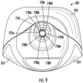
- Figure 9 shows an end view of the second end of the system unit, in an implementation.
- the end of bezel 710 is shown with the probe face 715 in the opening of the bezel.
- the probe face may include an aperture plate 720 that includes a number of source apertures, for example, source apertures 725a and 725b, and includes a number of detector apertures 730a-730h.
- Each of the source apertures may be included in a source structure that may include light sources, such as one or more of optical fibers, laser diodes, LEDs, one or more portions of the aperture plate, or other structures at the probe tip in any combination.
- Each of the detector apertures may be included in a detector structure that may include light detectors, such as one or more of optical fibers, photodetectors, one or more portions of the aperture plate, or other structures at the probe tip in any combination.
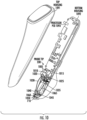
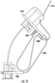
- the probe tip 338 is attached to a lower portion of the bottom housing.
- the probe tip may be connected to the bottom housing by mechanical fasteners, an adhesive (e.g., an glue, such as epoxy glue), another device, or any combination of these features.
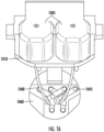
- the probe tip includes two reflector domes 1005, an LED PCB 1010, a first optical fiber holder 1020, a second optical fiber holder 1025, a third optical fiber holder 1040, a fourth optical fiber holder 1045, a first optical fiber 1030, a second optical fiber 1035, a first PCB 1050, a second PCB 1060, a first ribbon cable 1015, and a second ribbon cable 1065.
- Figure 11 shows the probe tip separate from the housing of the system unit and shows additional elements of the probe tip.
- the probe tip additionally includes an aperture plate 720, a first electrical connector 1080, and a second electrical connector 1085.
- Figure 12 shows a side view of the probe tip.
- a first end of ribbon cable 1065 is connected to second electrical connector 1085, which is mounted on LED PCB 1010.
- a second end of ribbon cable 1065 is connected to second PCB 1060.
- a first end of ribbon cable 1015 is connected to first electrical connector 1080, which is mounted on the LED PCB.
- a second end of ribbon cable 1015 is connected to the processor PCB 1093, such as via an electrical connector similar to connector 1080.
- the first ribbon cable transmits control signals from the processor to the LEDs mounted on the LED PCB so that the LEDs emit the described wavelengths.
- the second ribbon cable can transmit control signals from the processor to the photodetectors and can receive detection signals from the photodetectors.
- the received detection signals can be digitized signals that are digitized by an A-to-D converter that may be mounted on the processor PCB.
- the received signal may also be preprocessed by a DSP connected between the A-to-D converter and the processor.
- the first and second ribbon cable can be flexible printed cables (FPCs) or other types of ribbon cables.
- Connectors for connecting the ribbon cables to the PCBs can be flat flex connectors (FFCs) or other types of connectors.
- the optical fibers will emit light in a direction that is perpendicular to the probe face of the probe tip and perpendicular to a surface of tissue being measured.
- the known transmission angle of the light from the probe face allows for reliable transmission angle into the tissue and reliable oximetry measurements with a relatively high quality value.
- the first and second PCBs may each include apertures (two apertures) for the optical fibers (e.g., two optical fibers). End portions of the optical fibers may be located in the apertures and held in place by the third and fourth optical fiber holders that are mounted to the first side of the second PCB.
- the photodetectors are mounted on a second side of the first PCB.
- the aperture plate includes an aperture (e.g., ten apertures in total) for each photodetector (e.g., eight photodetectors) and for the optical fibers (e.g., two optical fibers). The end portions of the optical fibers can be located respectively in two of the apertures in the aperture plate.
- Figure 14 shows the first PCB 1050.
- the first PCB includes source apertures 1425a and 1425b through which the first and second optical fiber may extend.
- Detectors 1430a-1430h are mounted on the first PCB.
- Electrical trances of the first PCB 1050 are connected to electrical traces of the second PCB 1060.
- Figure 17 shows a top view of the LED PCB 1010.
- One or more LEDs e.g., four LEDs
- the LED PCB can include one or more aperture that portions of the optical fibers holder can extend into for adhesion of the optical fiber holder to the LED PBC.
- Figures 18A-18D show a number of steps for forming the probe face 715 of the probe tip 338 and forming the finished bezel 710 of the housing 1005 of the system unit 301.
- Figure 18a shows the bezel 710 of the housing 1005 at an initial height A where the height is from the outside surface of the housing to the top of the bezel. Height A may be from about 3.5 millimeters to about 4 millimeters. In a specific implementation, height A is about 3.75 millimeters.
- the inner height B of the bezel is from the inside surface of the housing to the top of the bezel. Height B may be from about 4.5 millimeters to about 5.5 millimeters. In a specific implementation, height B is about 5.05 millimeters.
- Figure 18B shows the housing and bezel with a portion of the probe tip 338 in the housing and bezel.
- the portion of the probe tip shown includes a first circuit board 1020, a second circuit board 1025, riser 1030, photodiodes 1035, an aperture plate 1040, and a ribbon cable 1045 connected to the second circuit board.
- the first and second circuit boards may include electrical traces that are coupled.
- the second circuit board may be a fiberglass circuit board (e.g., FR4) that includes electrical traces that are connected to electrical traces of the first circuit board.
- the electrical traces of the first circuit board may extend upward from the second circuit board along the outer surface of the first circuit board.
- the riser may be connected to both the first circuit board and the aperture plate and may separate the first circuit board and aperture plate may be predetermined height.
- the photodiodes may be mounted on a top surface of the first circuit board and be connected to the electrical traces of the first circuit board.
- the aperture plate may include an aperture for each photodiode that is mounted on the first surface of the first circuit board and the diodes may respectively be inside the apertures.
- the height of each riser may be about 100 micrometers to about 200 micrometers. In an implementation, the height of each riser is about 150 micrometers.
- the epoxy and a portion of the side of the bezel may be removed (e.g., polished down) to a final height, as shown in figure 18D .
- the final outside height H of the bezel may be about 2.0 millimeters to about 3 millimeters. In a specific implementation, the final outside height H of the bezel is about 2.58 millimeters.
- a portion of the aperture plate may also be thinned (e.g., polished thinner) when the bezel and epoxy are removed. The aperture place may be thinned to a final thickness from about 0.01 millimeters to about 0.03 millimeters (e.g., about 0.02 millimeters).
- a layer of epoxy is in the opening in the sidewall and over the front surface of the aperture plate that faces outward from the sidewall.
- the layer of epoxy may be from about 5 micrometers to about 50 micrometers.
Landscapes
- Health & Medical Sciences (AREA)
- Physics & Mathematics (AREA)
- Life Sciences & Earth Sciences (AREA)
- Biomedical Technology (AREA)
- Medical Informatics (AREA)
- Biophysics (AREA)
- Pathology (AREA)
- Engineering & Computer Science (AREA)
- Spectroscopy & Molecular Physics (AREA)
- Heart & Thoracic Surgery (AREA)
- Optics & Photonics (AREA)
- Molecular Biology (AREA)
- Surgery (AREA)
- Animal Behavior & Ethology (AREA)
- General Health & Medical Sciences (AREA)
- Public Health (AREA)
- Veterinary Medicine (AREA)
- Measurement Of The Respiration, Hearing Ability, Form, And Blood Characteristics Of Living Organisms (AREA)
Claims (15)
- Oximetervorrichtung, umfassend:ein Gehäuse (103, 705); undeine Sondenspitze (338), die von dem Gehäuse distal zu einem proximalen Ende des Gehäuses (103, 705) an einem distalen Ende des Gehäuses (103, 705) aufgenommen ist und von der Außenseite des Gehäuses (103, 705) an dem distalen Ende des Gehäuses (103, 705) sichtbar ist, wobei die Sondenspitze (338) an einen Prozessor gekoppelt ist,wobei die Sondenspitze (338) eine erste Leiterplatte, PCB, (1050), eine zweite PCB (1060) und eine erste an die erste und zweite PCB gekoppelte optische Faser (1030) zum Emittieren von Licht in Patientengewebe umfasst, die erste PCB (1050) näher an dem proximalen Ende des Gehäuses (103, 705) als die zweite PCB (1060) positioniert ist, die zweite PCB (1060) näher an dem distalen Ende des Gehäuses (103, 705) als die erste PCB (1050) positioniert ist, eine erste Fläche der ersten PCB (1050) dem distalen Ende des Gehäuses (103, 705) zugewandt ist, eine zweite Fläche der zweiten PCB (1060) dem proximalen Ende des Gehäuses (103, 705) zugewandt ist, dadurch gekennzeichnet, dass:
ein Winkel zwischen der ersten und der zweiten Fläche ungleich null ist und weniger als neunzig Grad beträgt, ein erster an der ersten PCB (1050) angeordneter Endabschnitt der ersten optischen Faser ungefähr quer zu der ersten Fläche der ersten PCB (1050) liegt, ein zweiter an der zweiten PCB (1060) angeordneter Endabschnitt der ersten optischen Faser ungefähr quer zu der zweiten Fläche der zweiten PCB (1060) liegt und ein Abschnitt der ersten optischen Faser zwischen dem ersten und zweiten Endabschnitt der ersten optischen Faser gekrümmt ist. - Vorrichtung nach Anspruch 1, umfassend einen ersten an die erste Fläche der ersten PCB (1050) gekoppelten Faserkoppler, wobei eine erste Faseröffnung in dem ersten Faserkoppler ausgebildet ist, der erste Endabschnitt der ersten optischen Faser in der ersten Faseröffnung positioniert ist und der erste Faserkoppler den ersten Endabschnitt der ersten optischen Faser quer zu der ersten Fläche der ersten PCB (1050) hält.
- Vorrichtung nach Anspruch 2, wobei der erste Faserkoppler eine erste Endfläche des ersten Endabschnitts der ersten optischen Faser parallel zu der ersten Fläche der ersten PCB (1050) hält.
- Vorrichtung nach Anspruch 2, umfassend einen zweiten an die zweite Fläche der zweiten PCB (1060) gekoppelten Faserkoppler, wobei eine zweite Faseröffnung in dem zweiten Faserkoppler ausgebildet ist, der zweite Endabschnitt der ersten optischen Faser in der zweiten Faseröffnung positioniert ist und der zweite Faserkoppler den zweiten Endabschnitt der ersten optischen Faser quer zu der zweiten Fläche der zweiten PCB (1060) hält.
- Vorrichtung nach Anspruch 4, wobei:der zweite Faserkoppler eine zweite Endfläche des zweiten Endabschnitts der ersten optischen Faser parallel zu der zweiten Fläche der zweiten PCB (1060) hält; oderdas Gehäuse (103, 705) eine an dem distalen Ende des Gehäuses (103, 705) angeordnete Einfassung umfasst, wobei die Sondenspitze (338) eine in der Einfassung angeordnete Öffnungsplatte umfasst, wobei die Öffnungsplatte eine dritte Faseröffnung umfasst, und der zweite Faserkoppler die Faser parallel zu der dritten Faseröffnung in der Öffnungsplatte ausrichtet.
- Vorrichtung nach Anspruch 1, wobei der Winkel zwischen der ersten und zweiten Fläche zwischen etwa 65 Grad und etwa 70 Grad beträgt.
- Vorrichtung nach Anspruch 1, umfassend:ein erstes Flachbandkabel, das die erste PCB (1050) an den Prozessor koppelt; und optionalein zweites Flachbandkabel, das die zweite PCB (1060) durch die erste PCB (1050) an den Prozessor koppelt.
- Vorrichtung nach Anspruch 7, umfassend:ein zweites Flachbandkabel, das die zweite PCB (1060) durch die erste PCB (1050) an den Prozessor koppelt; undwobei die Sondenspitze (338) eine an eine zweite Fläche der ersten PCB (1050) gekoppelte Leuchtdiode, LED; und ein die LED optisch an die erste optische Faser koppelndes Lichtlenkelement umfasst, wobei die erste und zweite Fläche der ersten PCB (1050) gegenüberliegende Flächen der ersten PCB (1050) sind.
- Vorrichtung nach Anspruch 1, wobei die Sondenspitze (338) eine zweite an die erste und zweite PCB gekoppelte optische Faser zum Emittieren von Licht in Patientengewebe umfasst, ein erster an der ersten PCB (1050) angeordneter Endabschnitt der zweiten optischen Faser ungefähr quer zu der ersten Fläche der ersten PCB (1050) liegt, ein zweiter an der zweiten PCB (1060) angeordneter Endabschnitt der zweiten optischen Faser ungefähr quer zu der zweiten Fläche der zweiten PCB (1060) liegt und ein Abschnitt der zweiten optischen Faser zwischen dem ersten und zweiten Endabschnitt der zweiten optischen Faser gekrümmt ist.
- Vorrichtung nach Anspruch 1, umfassend:
eine an dem distalen Ende des Gehäuses (103, 705) angeordnete Einfassung, wobei die Einfassung eine Seitenwand umfasst, wobei sich eine Öffnung der Einfassung von einem ersten Ende der Seitenwand zu einem zweiten Ende der Seitenwand erstreckt, wobei die Sondenspitze (338) eine Öffnungsplatte umfasst und die Öffnungsplatte in der Öffnung der Einfassung angeordnet ist, eine Fläche der Öffnungsplatte und eine obere Fläche der Seitenwand der Einfassung bündig sind und ein erster Abschnitt der ersten PCB (1050) an die Öffnungsplatte in der Öffnung der Einfassung gekoppelt ist. - Vorrichtung nach Anspruch 10, wobei die zweite PCB (1060) an die erste PCB (1050) außerhalb der Öffnung der Einfassung gekoppelt ist.
- Vorrichtung nach Anspruch 10, wobei die Sondenspitze (338) eine Vielzahl von Fotodetektoren umfasst, die auf einer Fläche der ersten PCB (1050) angeordnet ist, die an die Öffnungsplatte gekoppelt ist, wobei die Öffnungsplatte eine Vielzahl von Öffnungen beinhaltet und die Fotodetektoren an den Öffnungen der Öffnungsplatte innerhalb der Öffnung der Einfassung ausgerichtet sind.
- Vorrichtung nach Anspruch 12, wobei die Sondenspitze (338) Epoxid umfasst, das in der Öffnung der Einfassung angeordnet ist und eine Innenfläche der Seitenwand der Einfassung, die Öffnungsplatte, die Fotodetektoren und die erste PCB (1050) aneinander koppelt.
- Vorrichtung nach Anspruch 13, wobei eine Fläche des Epoxids bündig mit der Fläche der Öffnungsplatte und der oberen Fläche der Seitenwand der Einfassung ist.
- Verfahren zum Bereitstellen eines Oximeters, umfassend:Bereitstellen eines Gehäuses (103, 705);Bereitstellen einer Sondenspitze (338), die von einem Gehäuse an einem distalen Ende des Gehäuses (103, 705) aufgenommen ist und von der Außenseite des Gehäuses (103, 705) an dem distalen Ende des Gehäuses (103, 705) sichtbar ist, wobei die Sondenspitze (338) an einen Prozessor gekoppelt ist; undBereitstellen, dass die Sondenspitze (338) eine erste erste Leiterplatte, PCB, (1050), eine zweite PCB (1060) und eine erste an die erste und zweite PCB gekoppelte optische Faser (1030) zum Emittieren von Licht in Patientengewebe umfasst, die erste PCB (1050) näher an einem proximalen Ende des Gehäuses (103, 705) als die zweite PCB (1060) positioniert ist, die zweite PCB (1060) näher an dem distalen Ende des Gehäuses (103, 705) als die erste PCB (1050) positioniert ist, eine erste Fläche der ersten PCB (1050) dem distalen Ende des Gehäuses (103, 705) zugewandt ist, eine zweite Fläche der zweiten PCB (1060) dem proximalen Ende des Gehäuses (103, 705) zugewandt ist, dadurch gekennzeichnet, dass ein Winkel zwischen der ersten und der zweiten Fläche ungleich null ist und weniger als neunzig Grad beträgt, ein erster an der ersten PCB (1050) angeordneter Endabschnitt der ersten optischen Faser ungefähr quer zu der ersten Fläche der ersten PCB (1050) liegt, ein zweiter an der zweiten PCB (1060) angeordneter Endabschnitt der ersten optischen Faser ungefähr quer zu der zweiten Fläche der zweiten PCB (1060) liegt und ein Abschnitt der ersten optischen Faser zwischen dem ersten und zweiten Endabschnitt der ersten optischen Faser gekrümmt ist.
Applications Claiming Priority (2)
| Application Number | Priority Date | Filing Date | Title |
|---|---|---|---|
| US202062959787P | 2020-01-10 | 2020-01-10 | |
| PCT/US2021/013000 WO2021142466A1 (en) | 2020-01-10 | 2021-01-11 | Probe tip for medical device |
Publications (3)
| Publication Number | Publication Date |
|---|---|
| EP4087478A1 EP4087478A1 (de) | 2022-11-16 |
| EP4087478A4 EP4087478A4 (de) | 2024-05-15 |
| EP4087478B1 true EP4087478B1 (de) | 2025-04-09 |
Family
ID=76760667
Family Applications (1)
| Application Number | Title | Priority Date | Filing Date |
|---|---|---|---|
| EP21738817.2A Active EP4087478B1 (de) | 2020-01-10 | 2021-01-11 | Sondenspitze für medizinprodukt |
Country Status (5)
| Country | Link |
|---|---|
| US (2) | US11672448B2 (de) |
| EP (1) | EP4087478B1 (de) |
| CA (1) | CA3167154A1 (de) |
| TW (1) | TWI864217B (de) |
| WO (1) | WO2021142466A1 (de) |
Families Citing this family (3)
| Publication number | Priority date | Publication date | Assignee | Title |
|---|---|---|---|---|
| USD1029274S1 (en) * | 2016-04-19 | 2024-05-28 | Vioptix, Inc. | Medical device |
| US20240225497A1 (en) * | 2021-05-21 | 2024-07-11 | Universität Bern | Medical device comprising a wearable textile sensor to protect against pressure injuries |
| EP4418999A4 (de) | 2021-10-18 | 2025-07-02 | Vioptix Inc | In der hand gehaltenes oximeter mit anzeige von echtzeit-mittelwertmessungen und statusindikator |
Family Cites Families (23)
| Publication number | Priority date | Publication date | Assignee | Title |
|---|---|---|---|---|
| IL107396A (en) | 1992-11-09 | 1997-02-18 | Boehringer Mannheim Gmbh | Method and apparatus for analytical determination of glucose in a biological matrix |
| US6142629A (en) | 1998-08-30 | 2000-11-07 | Applied Spectral Imaging Ltd. | Spectral imaging using illumination of preselected spectral content |
| CN100381095C (zh) | 1998-11-18 | 2008-04-16 | Lea医药技术有限公司 | 非侵入地探测组织中氧代谢量的装置 |
| US6901221B1 (en) * | 1999-05-27 | 2005-05-31 | Jds Uniphase Corporation | Method and apparatus for improved optical elements for vertical PCB fiber optic modules |
| CA2417917C (en) | 2000-08-04 | 2014-10-14 | Photonify Technologies, Inc. | Systems and methods for providing information concerning chromophores in physiological media |
| US6516209B2 (en) | 2000-08-04 | 2003-02-04 | Photonify Technologies, Inc. | Self-calibrating optical imaging system |
| US6801648B2 (en) | 2000-08-04 | 2004-10-05 | Xuefeng Cheng | Optical imaging system with symmetric optical probe |
| US7091874B2 (en) | 2003-04-18 | 2006-08-15 | Smithson Bradley D | Temperature compensated warning light |
| US8733966B2 (en) | 2004-08-20 | 2014-05-27 | Mag Instrument, Inc. | LED flashlight |
| US8055321B2 (en) | 2005-03-14 | 2011-11-08 | Peter Bernreuter | Tissue oximetry apparatus and method |
| WO2008139763A1 (ja) * | 2007-05-14 | 2008-11-20 | Fujikura Ltd. | 光通信モジュールとその製造方法及び光送受信装置 |
| US9380966B2 (en) | 2007-06-22 | 2016-07-05 | Vioptix, Inc. | Tissue retractor oximeter |
| JP4077024B1 (ja) | 2007-07-13 | 2008-04-16 | 俊仁 勝村 | 運動負荷量測定装置 |
| US8116838B2 (en) * | 2007-11-27 | 2012-02-14 | Carnegie Mellon University | Medical device for diagnosing pressure ulcers |
| EP3556291B1 (de) | 2008-08-07 | 2025-05-14 | University of Massachusetts | Spektroskopische sensoren |
| US8311601B2 (en) | 2009-06-30 | 2012-11-13 | Nellcor Puritan Bennett Llc | Reflectance and/or transmissive pulse oximeter |
| SG191880A1 (en) | 2011-01-19 | 2013-08-30 | Univ California | Apparatus, systems, and methods for tissue oximetry and perfusion imaging |
| HK1202402A1 (en) * | 2012-05-03 | 2015-10-02 | Vioptix, Inc. | Tissue oximetry probe geometry for robust calibration and self-correction |
| CN104768461B (zh) | 2012-08-10 | 2017-09-12 | 维奥普蒂克斯公司 | 无线手持组织血氧测量装置 |
| WO2014178793A1 (en) * | 2013-04-29 | 2014-11-06 | Heptagon Micro Optics Pte. Ltd. | Wristwatch including an integrated pulse oximeter or other modules that sense physiological data |
| US10512407B2 (en) * | 2013-06-24 | 2019-12-24 | Fitbit, Inc. | Heart rate data collection |
| US20170049336A1 (en) * | 2014-05-01 | 2017-02-23 | Reveal Biosensors, Inc. | Physiological sensors, systems, kits and methods therefor |
| WO2018017501A1 (en) * | 2016-07-18 | 2018-01-25 | Vioptix, Inc. | Oximetry device with laparoscopic extension |
-
2021
- 2021-01-11 EP EP21738817.2A patent/EP4087478B1/de active Active
- 2021-01-11 WO PCT/US2021/013000 patent/WO2021142466A1/en not_active Ceased
- 2021-01-11 US US17/146,190 patent/US11672448B2/en active Active
- 2021-01-11 CA CA3167154A patent/CA3167154A1/en active Pending
- 2021-01-11 TW TW110100874A patent/TWI864217B/zh active
-
2023
- 2023-06-08 US US18/331,882 patent/US12138049B2/en active Active
Also Published As
| Publication number | Publication date |
|---|---|
| EP4087478A1 (de) | 2022-11-16 |
| US20230329598A1 (en) | 2023-10-19 |
| US12138049B2 (en) | 2024-11-12 |
| WO2021142466A1 (en) | 2021-07-15 |
| TWI864217B (zh) | 2024-12-01 |
| CA3167154A1 (en) | 2021-07-15 |
| EP4087478A4 (de) | 2024-05-15 |
| US20210212615A1 (en) | 2021-07-15 |
| US11672448B2 (en) | 2023-06-13 |
| TW202135732A (zh) | 2021-10-01 |
Similar Documents
| Publication | Publication Date | Title |
|---|---|---|
| US12138049B2 (en) | Probe tip assembly and bezel for medical device | |
| JP6745256B2 (ja) | ロバストな校正および自己補正のための組織オキシメトリプローブジオメトリ | |
| US20240389899A1 (en) | NFC Security for Medical Device and Sheath | |
| US20260013754A1 (en) | Protective Sheath for a Medical Device | |
| US20240057901A1 (en) | Oximeter with Quality Metric Indication | |
| US20250339063A1 (en) | Handheld Oximeter System With Reusable System Unit | |
| US12383170B2 (en) | Oximeter with StO2 averaging | |
| US12364406B2 (en) | Temperature control of medical device | |
| US20250064357A1 (en) | Probe Tip Assembly and Bezel for Medical Device |
Legal Events
| Date | Code | Title | Description |
|---|---|---|---|
| STAA | Information on the status of an ep patent application or granted ep patent |
Free format text: STATUS: THE INTERNATIONAL PUBLICATION HAS BEEN MADE |
|
| PUAI | Public reference made under article 153(3) epc to a published international application that has entered the european phase |
Free format text: ORIGINAL CODE: 0009012 |
|
| STAA | Information on the status of an ep patent application or granted ep patent |
Free format text: STATUS: REQUEST FOR EXAMINATION WAS MADE |
|
| 17P | Request for examination filed |
Effective date: 20220707 |
|
| AK | Designated contracting states |
Kind code of ref document: A1 Designated state(s): AL AT BE BG CH CY CZ DE DK EE ES FI FR GB GR HR HU IE IS IT LI LT LU LV MC MK MT NL NO PL PT RO RS SE SI SK SM TR |
|
| DAV | Request for validation of the european patent (deleted) | ||
| DAX | Request for extension of the european patent (deleted) | ||
| P01 | Opt-out of the competence of the unified patent court (upc) registered |
Effective date: 20230515 |
|
| RIC1 | Information provided on ipc code assigned before grant |
Ipc: G02B 6/38 20060101ALI20231215BHEP Ipc: A61B 5/00 20060101ALI20231215BHEP Ipc: G02B 6/24 20060101ALI20231215BHEP Ipc: A61B 5/145 20060101ALI20231215BHEP Ipc: A61B 5/1455 20060101AFI20231215BHEP |
|
| A4 | Supplementary search report drawn up and despatched |
Effective date: 20240412 |
|
| RIC1 | Information provided on ipc code assigned before grant |
Ipc: G02B 6/38 20060101ALI20240408BHEP Ipc: A61B 5/00 20060101ALI20240408BHEP Ipc: G02B 6/24 20060101ALI20240408BHEP Ipc: A61B 5/145 20060101ALI20240408BHEP Ipc: A61B 5/1455 20060101AFI20240408BHEP |
|
| GRAP | Despatch of communication of intention to grant a patent |
Free format text: ORIGINAL CODE: EPIDOSNIGR1 |
|
| STAA | Information on the status of an ep patent application or granted ep patent |
Free format text: STATUS: GRANT OF PATENT IS INTENDED |
|
| INTG | Intention to grant announced |
Effective date: 20241030 |
|
| GRAS | Grant fee paid |
Free format text: ORIGINAL CODE: EPIDOSNIGR3 |
|
| GRAA | (expected) grant |
Free format text: ORIGINAL CODE: 0009210 |
|
| STAA | Information on the status of an ep patent application or granted ep patent |
Free format text: STATUS: THE PATENT HAS BEEN GRANTED |
|
| AK | Designated contracting states |
Kind code of ref document: B1 Designated state(s): AL AT BE BG CH CY CZ DE DK EE ES FI FR GB GR HR HU IE IS IT LI LT LU LV MC MK MT NL NO PL PT RO RS SE SI SK SM TR |
|
| REG | Reference to a national code |
Ref country code: GB Ref legal event code: FG4D |
|
| REG | Reference to a national code |
Ref country code: CH Ref legal event code: EP |
|
| REG | Reference to a national code |
Ref country code: DE Ref legal event code: R096 Ref document number: 602021028928 Country of ref document: DE |
|
| REG | Reference to a national code |
Ref country code: IE Ref legal event code: FG4D |
|
| REG | Reference to a national code |
Ref country code: NL Ref legal event code: MP Effective date: 20250409 |
|
| PG25 | Lapsed in a contracting state [announced via postgrant information from national office to epo] |
Ref country code: NL Free format text: LAPSE BECAUSE OF FAILURE TO SUBMIT A TRANSLATION OF THE DESCRIPTION OR TO PAY THE FEE WITHIN THE PRESCRIBED TIME-LIMIT Effective date: 20250409 |
|
| REG | Reference to a national code |
Ref country code: AT Ref legal event code: MK05 Ref document number: 1782771 Country of ref document: AT Kind code of ref document: T Effective date: 20250409 |
|
| PG25 | Lapsed in a contracting state [announced via postgrant information from national office to epo] |
Ref country code: PT Free format text: LAPSE BECAUSE OF FAILURE TO SUBMIT A TRANSLATION OF THE DESCRIPTION OR TO PAY THE FEE WITHIN THE PRESCRIBED TIME-LIMIT Effective date: 20250811 Ref country code: ES Free format text: LAPSE BECAUSE OF FAILURE TO SUBMIT A TRANSLATION OF THE DESCRIPTION OR TO PAY THE FEE WITHIN THE PRESCRIBED TIME-LIMIT Effective date: 20250409 Ref country code: FI Free format text: LAPSE BECAUSE OF FAILURE TO SUBMIT A TRANSLATION OF THE DESCRIPTION OR TO PAY THE FEE WITHIN THE PRESCRIBED TIME-LIMIT Effective date: 20250409 |
|
| REG | Reference to a national code |
Ref country code: LT Ref legal event code: MG9D |
|
| PG25 | Lapsed in a contracting state [announced via postgrant information from national office to epo] |
Ref country code: NO Free format text: LAPSE BECAUSE OF FAILURE TO SUBMIT A TRANSLATION OF THE DESCRIPTION OR TO PAY THE FEE WITHIN THE PRESCRIBED TIME-LIMIT Effective date: 20250709 Ref country code: GR Free format text: LAPSE BECAUSE OF FAILURE TO SUBMIT A TRANSLATION OF THE DESCRIPTION OR TO PAY THE FEE WITHIN THE PRESCRIBED TIME-LIMIT Effective date: 20250710 |
|
| PG25 | Lapsed in a contracting state [announced via postgrant information from national office to epo] |
Ref country code: PL Free format text: LAPSE BECAUSE OF FAILURE TO SUBMIT A TRANSLATION OF THE DESCRIPTION OR TO PAY THE FEE WITHIN THE PRESCRIBED TIME-LIMIT Effective date: 20250409 |
|
| PG25 | Lapsed in a contracting state [announced via postgrant information from national office to epo] |
Ref country code: BG Free format text: LAPSE BECAUSE OF FAILURE TO SUBMIT A TRANSLATION OF THE DESCRIPTION OR TO PAY THE FEE WITHIN THE PRESCRIBED TIME-LIMIT Effective date: 20250409 |
|
| PG25 | Lapsed in a contracting state [announced via postgrant information from national office to epo] |
Ref country code: HR Free format text: LAPSE BECAUSE OF FAILURE TO SUBMIT A TRANSLATION OF THE DESCRIPTION OR TO PAY THE FEE WITHIN THE PRESCRIBED TIME-LIMIT Effective date: 20250409 |
|
| PG25 | Lapsed in a contracting state [announced via postgrant information from national office to epo] |
Ref country code: AT Free format text: LAPSE BECAUSE OF FAILURE TO SUBMIT A TRANSLATION OF THE DESCRIPTION OR TO PAY THE FEE WITHIN THE PRESCRIBED TIME-LIMIT Effective date: 20250409 |
|
| PG25 | Lapsed in a contracting state [announced via postgrant information from national office to epo] |
Ref country code: RS Free format text: LAPSE BECAUSE OF FAILURE TO SUBMIT A TRANSLATION OF THE DESCRIPTION OR TO PAY THE FEE WITHIN THE PRESCRIBED TIME-LIMIT Effective date: 20250709 |
|
| PG25 | Lapsed in a contracting state [announced via postgrant information from national office to epo] |
Ref country code: IS Free format text: LAPSE BECAUSE OF FAILURE TO SUBMIT A TRANSLATION OF THE DESCRIPTION OR TO PAY THE FEE WITHIN THE PRESCRIBED TIME-LIMIT Effective date: 20250809 |
|
| PG25 | Lapsed in a contracting state [announced via postgrant information from national office to epo] |
Ref country code: LV Free format text: LAPSE BECAUSE OF FAILURE TO SUBMIT A TRANSLATION OF THE DESCRIPTION OR TO PAY THE FEE WITHIN THE PRESCRIBED TIME-LIMIT Effective date: 20250409 |
|
| REG | Reference to a national code |
Ref country code: DE Ref legal event code: R097 Ref document number: 602021028928 Country of ref document: DE |
|
| PG25 | Lapsed in a contracting state [announced via postgrant information from national office to epo] |
Ref country code: DK Free format text: LAPSE BECAUSE OF FAILURE TO SUBMIT A TRANSLATION OF THE DESCRIPTION OR TO PAY THE FEE WITHIN THE PRESCRIBED TIME-LIMIT Effective date: 20250409 Ref country code: SM Free format text: LAPSE BECAUSE OF FAILURE TO SUBMIT A TRANSLATION OF THE DESCRIPTION OR TO PAY THE FEE WITHIN THE PRESCRIBED TIME-LIMIT Effective date: 20250409 |
|
| PG25 | Lapsed in a contracting state [announced via postgrant information from national office to epo] |
Ref country code: CZ Free format text: LAPSE BECAUSE OF FAILURE TO SUBMIT A TRANSLATION OF THE DESCRIPTION OR TO PAY THE FEE WITHIN THE PRESCRIBED TIME-LIMIT Effective date: 20250409 |
|
| PG25 | Lapsed in a contracting state [announced via postgrant information from national office to epo] |
Ref country code: EE Free format text: LAPSE BECAUSE OF FAILURE TO SUBMIT A TRANSLATION OF THE DESCRIPTION OR TO PAY THE FEE WITHIN THE PRESCRIBED TIME-LIMIT Effective date: 20250409 |
|
| PG25 | Lapsed in a contracting state [announced via postgrant information from national office to epo] |
Ref country code: SK Free format text: LAPSE BECAUSE OF FAILURE TO SUBMIT A TRANSLATION OF THE DESCRIPTION OR TO PAY THE FEE WITHIN THE PRESCRIBED TIME-LIMIT Effective date: 20250409 |
|
| PG25 | Lapsed in a contracting state [announced via postgrant information from national office to epo] |
Ref country code: IT Free format text: LAPSE BECAUSE OF FAILURE TO SUBMIT A TRANSLATION OF THE DESCRIPTION OR TO PAY THE FEE WITHIN THE PRESCRIBED TIME-LIMIT Effective date: 20250409 |
|
| PLBE | No opposition filed within time limit |
Free format text: ORIGINAL CODE: 0009261 |
|
| STAA | Information on the status of an ep patent application or granted ep patent |
Free format text: STATUS: NO OPPOSITION FILED WITHIN TIME LIMIT |
|
| REG | Reference to a national code |
Ref country code: CH Ref legal event code: L10 Free format text: ST27 STATUS EVENT CODE: U-0-0-L10-L00 (AS PROVIDED BY THE NATIONAL OFFICE) Effective date: 20260218 |
|
| 26N | No opposition filed |
Effective date: 20260112 |
|
| PGFP | Annual fee paid to national office [announced via postgrant information from national office to epo] |
Ref country code: GB Payment date: 20260127 Year of fee payment: 6 |
|
| PGFP | Annual fee paid to national office [announced via postgrant information from national office to epo] |
Ref country code: DE Payment date: 20260128 Year of fee payment: 6 |
|
| PGFP | Annual fee paid to national office [announced via postgrant information from national office to epo] |
Ref country code: FR Payment date: 20260126 Year of fee payment: 6 |