EP4087227A1 - Electronic device - Google Patents
Electronic device Download PDFInfo
- Publication number
- EP4087227A1 EP4087227A1 EP20906442.7A EP20906442A EP4087227A1 EP 4087227 A1 EP4087227 A1 EP 4087227A1 EP 20906442 A EP20906442 A EP 20906442A EP 4087227 A1 EP4087227 A1 EP 4087227A1
- Authority
- EP
- European Patent Office
- Prior art keywords
- flight
- camera
- device shell
- photographing
- flight photographing
- Prior art date
- Legal status (The legal status is an assumption and is not a legal conclusion. Google has not performed a legal analysis and makes no representation as to the accuracy of the status listed.)
- Pending
Links
Images



Classifications
-
- H—ELECTRICITY
- H04—ELECTRIC COMMUNICATION TECHNIQUE
- H04M—TELEPHONIC COMMUNICATION
- H04M1/00—Substation equipment, e.g. for use by subscribers
- H04M1/02—Constructional features of telephone sets
- H04M1/0202—Portable telephone sets, e.g. cordless phones, mobile phones or bar type handsets
- H04M1/026—Details of the structure or mounting of specific components
- H04M1/0264—Details of the structure or mounting of specific components for a camera module assembly
-
- H—ELECTRICITY
- H04—ELECTRIC COMMUNICATION TECHNIQUE
- H04N—PICTORIAL COMMUNICATION, e.g. TELEVISION
- H04N23/00—Cameras or camera modules comprising electronic image sensors; Control thereof
- H04N23/50—Constructional details
-
- B—PERFORMING OPERATIONS; TRANSPORTING
- B64—AIRCRAFT; AVIATION; COSMONAUTICS
- B64C—AEROPLANES; HELICOPTERS
- B64C13/00—Control systems or transmitting systems for actuating flying-control surfaces, lift-increasing flaps, air brakes, or spoilers
- B64C13/24—Transmitting means
- B64C13/26—Transmitting means without power amplification or where power amplification is irrelevant
- B64C13/28—Transmitting means without power amplification or where power amplification is irrelevant mechanical
-
- B—PERFORMING OPERATIONS; TRANSPORTING
- B64—AIRCRAFT; AVIATION; COSMONAUTICS
- B64D—EQUIPMENT FOR FITTING IN OR TO AIRCRAFT; FLIGHT SUITS; PARACHUTES; ARRANGEMENT OR MOUNTING OF POWER PLANTS OR PROPULSION TRANSMISSIONS IN AIRCRAFT
- B64D47/00—Equipment not otherwise provided for
- B64D47/08—Arrangements of cameras
-
- B—PERFORMING OPERATIONS; TRANSPORTING
- B64—AIRCRAFT; AVIATION; COSMONAUTICS
- B64U—UNMANNED AERIAL VEHICLES [UAV]; EQUIPMENT THEREFOR
- B64U10/00—Type of UAV
- B64U10/10—Rotorcrafts
- B64U10/13—Flying platforms
- B64U10/14—Flying platforms with four distinct rotor axes, e.g. quadcopters
-
- B—PERFORMING OPERATIONS; TRANSPORTING
- B64—AIRCRAFT; AVIATION; COSMONAUTICS
- B64U—UNMANNED AERIAL VEHICLES [UAV]; EQUIPMENT THEREFOR
- B64U20/00—Constructional aspects of UAVs
- B64U20/40—Modular UAVs
-
- B—PERFORMING OPERATIONS; TRANSPORTING
- B64—AIRCRAFT; AVIATION; COSMONAUTICS
- B64U—UNMANNED AERIAL VEHICLES [UAV]; EQUIPMENT THEREFOR
- B64U30/00—Means for producing lift; Empennages; Arrangements thereof
- B64U30/20—Rotors; Rotor supports
- B64U30/26—Ducted or shrouded rotors
-
- B—PERFORMING OPERATIONS; TRANSPORTING
- B64—AIRCRAFT; AVIATION; COSMONAUTICS
- B64U—UNMANNED AERIAL VEHICLES [UAV]; EQUIPMENT THEREFOR
- B64U70/00—Launching, take-off or landing arrangements
- B64U70/50—Launching from storage containers, e.g. from submarine missile tubes
-
- B—PERFORMING OPERATIONS; TRANSPORTING
- B64—AIRCRAFT; AVIATION; COSMONAUTICS
- B64U—UNMANNED AERIAL VEHICLES [UAV]; EQUIPMENT THEREFOR
- B64U80/00—Transport or storage specially adapted for UAVs
- B64U80/10—Transport or storage specially adapted for UAVs with means for moving the UAV to a supply or launch location, e.g. robotic arms or carousels
-
- B—PERFORMING OPERATIONS; TRANSPORTING
- B64—AIRCRAFT; AVIATION; COSMONAUTICS
- B64U—UNMANNED AERIAL VEHICLES [UAV]; EQUIPMENT THEREFOR
- B64U80/00—Transport or storage specially adapted for UAVs
- B64U80/20—Transport or storage specially adapted for UAVs with arrangements for servicing the UAV
- B64U80/25—Transport or storage specially adapted for UAVs with arrangements for servicing the UAV for recharging batteries; for refuelling
-
- B—PERFORMING OPERATIONS; TRANSPORTING
- B64—AIRCRAFT; AVIATION; COSMONAUTICS
- B64U—UNMANNED AERIAL VEHICLES [UAV]; EQUIPMENT THEREFOR
- B64U80/00—Transport or storage specially adapted for UAVs
- B64U80/60—Transport or storage specially adapted for UAVs by wearable objects, e.g. garments or helmets
-
- H—ELECTRICITY
- H04—ELECTRIC COMMUNICATION TECHNIQUE
- H04M—TELEPHONIC COMMUNICATION
- H04M1/00—Substation equipment, e.g. for use by subscribers
- H04M1/02—Constructional features of telephone sets
- H04M1/0202—Portable telephone sets, e.g. cordless phones, mobile phones or bar type handsets
- H04M1/0254—Portable telephone sets, e.g. cordless phones, mobile phones or bar type handsets comprising one or a plurality of mechanically detachable modules
- H04M1/0256—Portable telephone sets, e.g. cordless phones, mobile phones or bar type handsets comprising one or a plurality of mechanically detachable modules wherein the modules are operable in the detached state, e.g. one module for the user interface and one module for the transceiver
-
- H—ELECTRICITY
- H04—ELECTRIC COMMUNICATION TECHNIQUE
- H04N—PICTORIAL COMMUNICATION, e.g. TELEVISION
- H04N23/00—Cameras or camera modules comprising electronic image sensors; Control thereof
- H04N23/50—Constructional details
- H04N23/54—Mounting of pick-up tubes, electronic image sensors, deviation or focusing coils
-
- H—ELECTRICITY
- H04—ELECTRIC COMMUNICATION TECHNIQUE
- H04N—PICTORIAL COMMUNICATION, e.g. TELEVISION
- H04N23/00—Cameras or camera modules comprising electronic image sensors; Control thereof
- H04N23/57—Mechanical or electrical details of cameras or camera modules specially adapted for being embedded in other devices
-
- H—ELECTRICITY
- H04—ELECTRIC COMMUNICATION TECHNIQUE
- H04N—PICTORIAL COMMUNICATION, e.g. TELEVISION
- H04N23/00—Cameras or camera modules comprising electronic image sensors; Control thereof
- H04N23/90—Arrangement of cameras or camera modules, e.g. multiple cameras in TV studios or sports stadiums
-
- B—PERFORMING OPERATIONS; TRANSPORTING
- B64—AIRCRAFT; AVIATION; COSMONAUTICS
- B64U—UNMANNED AERIAL VEHICLES [UAV]; EQUIPMENT THEREFOR
- B64U2101/00—UAVs specially adapted for particular uses or applications
- B64U2101/30—UAVs specially adapted for particular uses or applications for imaging, photography or videography
-
- B—PERFORMING OPERATIONS; TRANSPORTING
- B64—AIRCRAFT; AVIATION; COSMONAUTICS
- B64U—UNMANNED AERIAL VEHICLES [UAV]; EQUIPMENT THEREFOR
- B64U30/00—Means for producing lift; Empennages; Arrangements thereof
- B64U30/20—Rotors; Rotor supports
-
- H—ELECTRICITY
- H04—ELECTRIC COMMUNICATION TECHNIQUE
- H04M—TELEPHONIC COMMUNICATION
- H04M1/00—Substation equipment, e.g. for use by subscribers
- H04M1/02—Constructional features of telephone sets
- H04M1/0202—Portable telephone sets, e.g. cordless phones, mobile phones or bar type handsets
- H04M1/0206—Portable telephones comprising a plurality of mechanically joined movable body parts, e.g. hinged housings
- H04M1/0208—Portable telephones comprising a plurality of mechanically joined movable body parts, e.g. hinged housings characterized by the relative motions of the body parts
- H04M1/0235—Slidable or telescopic telephones, i.e. with a relative translation movement of the body parts; Telephones using a combination of translation and other relative motions of the body parts
Definitions
- the present invention relates to the technical field of communication devices, and in particular, to an electronic device.
- an existing electronic device usually adopts a liftable camera module.
- the camera module needs to work, the camera module extends out of a device shell of the electronic device; and after the work of the camera module is completed, the camera module retracts into the device shell of the electronic device so as to be hidden in the device shell.
- the camera module with this structure can avoid the influence on the area of the display screen, so that the screen-to-body ratio of the electronic device can be increased.
- the existing camera module only can photograph images when extending out of the device shell, photographing only can be performed within the limited working distance of the camera module, and longer-distance photographing cannot be realized.
- the existing camera module requires a user to grasp the electronic device in the photographing process, and can adjust the photographing angle by adjusting body posture, so there is a problem of poor photographing flexibility.
- the present invention discloses an electronic device so as to solve the problem of poor photographing flexibility of a lifting camera of the existing electronic device.
- the present invention adopts the following technical solutions.
- An electronic device includes a device shell and a flight photographing device, wherein the device shell is provided with an opening and an inner cavity; the opening communicates with the inner cavity; the flight photographing device is movably disposed on the device shell; the flight photographing device is capable of extending out of the device shell or retracting into the device shell through the opening; and in a case that the flight photographing device is located outside the device shell, the flight photographing device is separable from the device shell.
- the technical solutions used by the present invention can achieve the following beneficial effects: according to the electronic device disclosed by the embodiments of the present invention, the structure of the electronic device in the prior art is improved, so that the electronic device is provided with the flight photographing device, the flight photographing device is detachably connected to the device shell, the flight photographing device can retract into the device shell through the opening, and the flight photographing device is hidden in the device shell.
- the flight photographing device extends out of the device shell and is separated from the device shell, so that the flight photographing device performs flight photographing, the flight photographing device can adjust its own position under the flight state, and flexible photographing can be realized. It can be seen that the electronic device disclosed by the embodiments of the present invention can improve the photographing flexibility of the electronic device.
- references numerals 100-device shell, 210-mounting bracket, 220-flight photographing device, 221-cabinet, 2211-cabinet main body, 2211a-mounting hole, 2212-cover body, 221a-first photographing window, 221b-second photographing window, 222-first camera, 223-battery, 224-propellers, 225-second camera, 226-device bracket, 227-infrared proximity sensor, 228-sealing cover, 300-first driving mechanism.
- the embodiments of the present invention disclose an electronic device.
- the electronic device includes a device shell 100 and a flight photographing device 220.
- the device shell 100 is a basic component of the electronic device, and the device shell 100 can provide a mounting position for other components of the electronic device.
- the device shell 100 is provided with an opening and an inner cavity, and the opening communicates with the inner cavity. The opening may allow the flight photographing device 220 to enter and exit the device shell 100 so as to change the position of the flight photographing device 220.
- the flight photographing device 220 is movably disposed on the device shell 100, and the flight photographing device 220 may extend out of the device shell 100 or retract into the device shell 100 through the opening. In a case that the flight photographing device 220 retracts into the device shell 100 through the opening, the flight photographing device 220 can be hidden and mounted in the device shell 100.
- the flight photographing device 220 is detachably connected to the device shell 100. In a case that the flight photographing device 220 extends out of the device shell 100 through the opening, the flight photographing device 220 is separable from the device shell 100, so that the flight photographing device 220 can be separated from the device shell 100 to fly. In the flight process, the flight photographing device 220 can adjust its own position in the air so as to realize photographing in various directions and finally realize more flexible photographing.
- the structure of the electronic device in the prior art is improved, so that the electronic device is provided with the flight photographing device 220, the flight photographing device 220 is detachably connected to the device shell 100, the flight photographing device 220 can retract into the device shell 100 through the opening, and the flight photographing device is hidden in the device shell 100.
- the flight photographing device 220 extends out of the device shell 100 and is separated from the device shell 100, so that the flight photographing device 220 performs flight photographing, the flight photographing device 220 can adjust its own position under the flight state, and flexible photographing can be realized. It can be seen that the electronic device disclosed by the embodiments of the present invention can improve the photographing flexibility of the electronic device.
- the flight photographing device 220 and the device shell 100 are in a detachable assembling state.
- the flight photographing device 220 and the device shell 100 may be assembled through magnetic attraction, buckling connection and other detachable modes.
- an electromagnetic piece may be disposed in the device shell 100.
- the electromagnetic piece may be powered on so as to generate a magnetic force to attract the flight photographing device 220, thereby realizing assembling.
- the electromagnetic piece is powered off, the magnetic attraction between the flight photographing device 220 and the device shell 100 is relieved.
- the device shell 100 may be provided with a first buckle, and the flight photographing device 220 may be provided with a second buckle.
- the first buckle cooperates with the second buckle so as to realize detachable assembling between the flight photographing device 220 and the device shell 100.
- the flight photographing device 220 and the device shell 100 may be detachably assembled through other modes.
- the movement of the flight photographing device 220 may be realized through manual control of a user.
- the device shell 100 may be provided with a sliding button.
- the sliding button may cooperate with the flight photographing device 220.
- the sliding button can slide to toggle the flight photographing device 220 to extend out of the device shell 100 through the opening.
- the cooperation between the flight photographing device 220 and the device shell 100 may be relieved (for example, the first buckle and the second buckle are released), thereby preparing for the separation of the flight photographing device and the device shell 100 in a case that the flight photographing device 220 is located outside the device shell 100.
- the electronic device disclosed by the embodiments of the present invention may further include a mounting bracket 210, the flight photographing device 220 is disposed on the mounting bracket 210, and the flight photographing device 220 may extend out of the device shell 100 or retract into the device shell 100 along with the mounting bracket 210 through the opening.
- the flight photographing device 220 retracts into the device shell 100 along with the mounting bracket 210, the flight photographing device 220 is detachably connected to the device shell 100 through the mounting bracket 210.
- the flight photographing device 220 extends out of the device shell 100 along with the mounting bracket 210, the flight photographing device 220 is separable from the mounting bracket 210 so as to be separated from the device shell 100.
- the configuration of the mounting bracket 210 facilitates the assembling between the flight photographing device 220 and the device shell 100.
- the mounting bracket 210 may be provided with a mounting space, the flight photographing device 220 may be placed in the mounting space, and in a case that the flight photographing device 220 extends out of the device shell 100, the flight photographing device 220 directly flies away.
- the mounting space may be a mounting groove.
- the electronic device disclosed by the embodiments of the present invention may further include a first driving mechanism 300, and the first driving mechanism 300 is disposed in the device shell 100.
- the first driving mechanism 300 is connected to the flight photographing device 220, and the first driving mechanism 300 drives the flight photographing device 220 to extend out of the device shell 100 or retract into the device shell 100 through the opening.
- the first driving mechanism 300 is detachably connected to the flight photographing device 220, thereby indirectly realizing detachable connection with the device shell 100.
- the flight photographing device 220 extends out of the device shell 100, the flight photographing device can be separated from the first driving mechanism 300 so as to be separated from the device shell 100.
- the first driving mechanism 300 can facilitate and intelligentize the movement control of the flight photographing device 220, so that use of a user can be facilitated.
- the first driving mechanism 300 may be a screw rod driving mechanism, a hydraulic telescopic piece, a pneumatic telescopic piece, a linear motor and other driving devices.
- the specific types of the first driving mechanism 300 are not limited in the embodiments of the present invention.
- the first driving mechanism 300 and the flight photographing device 220 may be connected through magnetic attraction.
- a part of the first driving mechanism 300 driving the flight photographing device 220 to move may include an electromagnetic piece, and the flight photographing device is provided with a magnet or a magnetic attraction piece attracted by magnetism.
- the electromagnetic piece is powered on, the first driving mechanism 300 is connected to the flight photographing device 220 through magnetic adsorption.
- connection between the first driving mechanism 300 and the flight photographing device 220 is released due to the demagnetization of the electromagnetic piece.
- the first driving mechanism 300 may be in driving connection with the mounting bracket 210, and the first driving mechanism 300 drives the mounting bracket 210 to drive the flight photographing device 220 to extend out of the device shell 100 or retract into the device shell 100 through the opening.
- the flight photographing device 220 may be placed in the mounting space of the mounting bracket 210, so the first driving mechanism 300 drives the mounting bracket 210 to drive the flight photographing device 220 to enter and exit the device shell 100.
- the flight photographing device 220 may directly fly away, and it is unnecessary to directly arrange a detachable structure between the flight photographing device 220 and the device shell 100, which can undoubtedly simplify the operation of a user and facilitate the use of the user.
- the electronic device disclosed by the embodiments of the present invention includes a mounting bracket 210
- the mounting bracket 210 may further be provided with at least one of a light supplement module, a receiver, a fingerprint recognition module and a USB interface.
- the influence on the arrangement area of the display screen of the electronic device by the above functional device can be avoided, so that the screen-to-body ratio of the electronic device can be further increased.
- the above functional device may extend out of the device shell 100 through the opening along with the mounting bracket 210. After the work, the above functional device may retract into the device shell 100 through the opening along with the mounting bracket 210, so that the functional device can be hidden in the device shell 100.
- the mounting bracket 210 is in sliding connection with the device shell 100 through a sliding rail.
- An opening of the device shell 100 is provided with a limiting structure.
- the limiting structure of the opening limits the mounting bracket 210 from further sliding out, and the mounting bracket 210 is not separated from the device shell 100.
- the flight photographing device 220 is supported on the mounting bracket, and a user may manually take out the flight photographing device 220.
- the flight photographing device 220 may have various structures.
- the flight photographing device 220 includes a cabinet 221, and a first camera 222, a battery 223, propellers 224 and a second driving mechanism which are disposed on the cabinet 221, wherein the second driving mechanism is in driving connection with the propellers 224 and drives the propellers 224 to rotate, and the battery 223 is connected to the first camera 222 and the second driving mechanism through power supply.
- the propellers 224 are driven by the second driving mechanism to rotate so as to drive the whole flight photographing device 220 to fly.
- the flight photographing device 220 can adjust its own position, so that the first camera 222 can perform photographing flexibly.
- the cabinet 221 disclosed by the embodiments of the present invention may include a top wall, a bottom wall and a side wall for connecting the top wall and the bottom wall, the side wall is provided with a first photographing window 221a, the first camera 222 is disposed in the cabinet 221, and a lens of the first camera 222 and the first photographing window 221a are arranged oppositely.
- the first camera 222 can realize lateral photographing of the flight photographing device 220 through the first photographing window 221a on the side wall, which undoubtedly can meet the lateral photographing of the flight photographing device 220.
- the first camera 222 is disposed in the cabinet 221, so that the first camera can be protected by the cabinet 221 and damage caused by bump in the flight process can be avoided.
- the flight photographing device 220 disclosed by the embodiments of the present invention may further include a second camera 225, the second camera 225 is disposed in the cabinet 221, the bottom wall is provided with a second photographing window 221b, and a lens of the second camera 225 and the second photographing window 221b are arranged oppositely.
- the second camera 225 of the flight photographing device 220 can perform overlooking photographing through the second photographing window 221b.
- the second camera 225 is disposed in the cabinet 221, so that the second camera can be protected by the cabinet 221.
- the second camera 225 may be used to detect altitude data of an object through overlooking photographing.
- the flight photographing device 220 disclosed by the embodiments of the present invention may further include a device bracket 226, the device bracket 226 is disposed in the cabinet 221, and the first camera 222, the second camera 225 and the battery 223 are all mounted on the device bracket 226.
- the first camera 222, the second camera 225 and the battery 223 may be mounted on the device bracket 226 in advance, then form a modular structure together with the device bracket 226, and are integrally mounted in the cabinet 221, which can undoubtedly improve the assembling efficiency.
- the side wall of the cabinet 221 is provided with a first photographing window 221a.
- the number of the side walls may be four
- the first photographing window 221a is disposed on one side wall
- the other three side walls and the bottom wall may be provided with proximity sensors
- the proximity sensors can prevent the flight photographing device 220 from colliding with other objects in the flight process.
- the proximity sensors may be infrared proximity sensors 227. This can undoubtedly improve the flight safety of the flight photographing device 220.
- the top wall may also be provided with a proximity sensor.
- the flight photographing device 220 disclosed by the embodiments of the present invention may include a third camera and a fourth camera, the third camera and the fourth camera may be disposed outside the cabinet 221 respectively, the third camera and the fourth camera may be distributed opposite to each other, the third camera and the fourth camera are hinged with a spherical surface of the cabinet 221, photographing in a larger field of view can be realized by adjusting the angles of the third camera and the fourth camera, and certainly, more photographing viewing angles can be realized.
- the flight photographing device 220 may be one propeller 224, or may include a plurality of propellers 224.
- the plurality of propellers 224 are arranged at intervals, and the plurality of propellers 224 jointly act so as to enable the flight photographing device 220 to fly more stably.
- the number of the propellers 224 is four, the four propellers 224 are sequentially disposed at four corners of the cabinet 221, and the two diagonally distributed propellers 224 and the other two diagonally distributed propellers 224 may have opposite rotating directions, so that the driving balance is realized, and the flight photographing device 220 can maintain the position better.
- the number of the second driving mechanism may be one or more. In a case that the number of the second driving mechanism is one, the second driving mechanism may drive all propellers 224 to rotate through a transmission mechanism. In an optional solution, the number of the driving mechanisms is equal to the number of the propellers 224, and each second driving mechanism is in driving connection with one propeller 224.
- One second driving mechanism is singly configured for each propeller 224, so that the flight photographing device 220 does not require a complex power transmission mechanism, which is beneficial to simplifying the overall structure of the flight photographing device 220.
- the second driving mechanism when there are a plurality of second driving mechanisms, in a case that some of the second driving mechanisms are in failure and stop operation, due to the driving of the other second driving mechanisms, continuous flight of the flight photographing device 220 can be maintained.
- the cabinet 221 may include a cabinet main body 2211 and a cover body 2212, the cover body 2212 is fixed on the opening of the cabinet main body 2211, the propellers 224 and the second driving mechanism are mounted on the cabinet main body 2211, the cover body 2212 is provided with an avoidance gap, and the avoidance gap is arranged along a partial edge of the propellers 224.
- the propellers 224 and the second driving mechanism are mounted on the cabinet main body 2211, so that assembling between the propellers and the second driving mechanism is convenient to realize on the same mounting basis.
- the cover body 2212 may be fixed on the cabinet body 2211 through clamping connection, threaded connection and other fixing modes.
- the side wall (that is, the side wall of the cabinet 221) of the cabinet main body 2211 may be provided with a mounting hole 2211a
- the cabinet 221 may further include a sealing cover 228, the sealing cover 228 may be provided with a charging contact, and the charging contact is electrically connected to a battery 223, so that the flight photographing device 220 can be charged.
- the separate sealing cover 228 is undoubtedly more convenient to arrange a charging connection structure thereon.
- the sealing cover 228 may be detachably connected to the mounting hole 2211a, so that it is convenient for a user to disassemble the sealing cover 228 to maintain the partial structure of the flight photographing device 220.
- the electronic device disclosed by the embodiments of the present invention may be a smart phone, a tablet computer, an e-book reader, a wearable device (such as a smartwatch), a game machine and the like.
- the electronic device disclosed by the embodiments of the present invention may be other types, and the specific types of the electronic device are not limited in the embodiments of the present invention.
Landscapes
- Engineering & Computer Science (AREA)
- Remote Sensing (AREA)
- Aviation & Aerospace Engineering (AREA)
- Signal Processing (AREA)
- Mechanical Engineering (AREA)
- Multimedia (AREA)
- Transportation (AREA)
- Automation & Control Theory (AREA)
- Human Computer Interaction (AREA)
- Robotics (AREA)
- Studio Devices (AREA)
Abstract
Description
- This application claims priority to
Chinese Patent Application No. 201911376440.6 filed in China on December 27, 2019 - The present invention relates to the technical field of communication devices, and in particular, to an electronic device.
- As user demands increase, performance of electronic devices is continuously optimized, wherein the more prominent performance is that the screen-to-body ratio of the electronic device is increasing. In order to further increase the screen-to-body ratio of the electronic device, an existing electronic device usually adopts a liftable camera module. When the camera module needs to work, the camera module extends out of a device shell of the electronic device; and after the work of the camera module is completed, the camera module retracts into the device shell of the electronic device so as to be hidden in the device shell. The camera module with this structure can avoid the influence on the area of the display screen, so that the screen-to-body ratio of the electronic device can be increased.
- However, the existing camera module only can photograph images when extending out of the device shell, photographing only can be performed within the limited working distance of the camera module, and longer-distance photographing cannot be realized. At the same time, the existing camera module requires a user to grasp the electronic device in the photographing process, and can adjust the photographing angle by adjusting body posture, so there is a problem of poor photographing flexibility.
- The present invention discloses an electronic device so as to solve the problem of poor photographing flexibility of a lifting camera of the existing electronic device.
- To solve the foregoing problem, the present invention adopts the following technical solutions.
- An electronic device includes a device shell and a flight photographing device, wherein the device shell is provided with an opening and an inner cavity; the opening communicates with the inner cavity; the flight photographing device is movably disposed on the device shell; the flight photographing device is capable of extending out of the device shell or retracting into the device shell through the opening; and in a case that the flight photographing device is located outside the device shell, the flight photographing device is separable from the device shell.
- The technical solutions used by the present invention can achieve the following beneficial effects:
according to the electronic device disclosed by the embodiments of the present invention, the structure of the electronic device in the prior art is improved, so that the electronic device is provided with the flight photographing device, the flight photographing device is detachably connected to the device shell, the flight photographing device can retract into the device shell through the opening, and the flight photographing device is hidden in the device shell. When it is necessary to photograph, the flight photographing device extends out of the device shell and is separated from the device shell, so that the flight photographing device performs flight photographing, the flight photographing device can adjust its own position under the flight state, and flexible photographing can be realized. It can be seen that the electronic device disclosed by the embodiments of the present invention can improve the photographing flexibility of the electronic device. - The accompanying drawings described herein are used to provide further understanding of the present invention and constitute a part of the present invention. The illustrative embodiments of the present invention and descriptions thereof are used to explain the present invention, and do not constitute any improper limitation on the present invention. In the accompanying drawings.
-
FIG. 1 is a structural schematic diagram of an electronic device according to an embodiment of the present; -
FIG. 2 is a schematic diagram of the flight photographing device in the extended state inFIG. 1 ; -
FIG. 3 is a schematic diagram of a partial structure of an electronic device according to an embodiment of the present invention; -
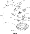
FIG. 4 is a schematic diagram of an exploded structure of a flight photographing device; -
FIG. 5 is a schematic enlarged view of a partial structure ofFIG. 4 ; and -
FIG. 6 is a structural schematic diagram of a flight photographing device according to an embodiment of the present invention from another perspective. - Description of reference numerals:
100-device shell, 210-mounting bracket, 220-flight photographing device, 221-cabinet, 2211-cabinet main body, 2211a-mounting hole, 2212-cover body, 221a-first photographing window, 221b-second photographing window, 222-first camera, 223-battery, 224-propellers, 225-second camera, 226-device bracket, 227-infrared proximity sensor, 228-sealing cover, 300-first driving mechanism. - To make the objectives, technical solutions and advantages of the present invention clearer, the following clearly and completely describes the technical solutions of the present invention with reference to the specific embodiments of the present invention and the corresponding accompanying drawings. Apparently, the described embodiments are merely a part rather than all of the embodiments of the present invention. All other embodiments obtained by a person of ordinary skill in the art based on the embodiments of the present invention without creative efforts shall fall within the protection scope of the present invention.
- The technical solutions disclosed by various embodiments of the present invention are described in detail below with reference to the accompanying drawings.
- Referring to
FIG. 1 to FIG. 6 , the embodiments of the present invention disclose an electronic device. The electronic device includes adevice shell 100 and aflight photographing device 220. - The
device shell 100 is a basic component of the electronic device, and thedevice shell 100 can provide a mounting position for other components of the electronic device. In the embodiments of the present invention, thedevice shell 100 is provided with an opening and an inner cavity, and the opening communicates with the inner cavity. The opening may allow theflight photographing device 220 to enter and exit thedevice shell 100 so as to change the position of theflight photographing device 220. - In the embodiments of the present invention, the
flight photographing device 220 is movably disposed on thedevice shell 100, and theflight photographing device 220 may extend out of thedevice shell 100 or retract into thedevice shell 100 through the opening. In a case that theflight photographing device 220 retracts into thedevice shell 100 through the opening, theflight photographing device 220 can be hidden and mounted in thedevice shell 100. - The
flight photographing device 220 is detachably connected to thedevice shell 100. In a case that theflight photographing device 220 extends out of thedevice shell 100 through the opening, theflight photographing device 220 is separable from thedevice shell 100, so that theflight photographing device 220 can be separated from thedevice shell 100 to fly. In the flight process, theflight photographing device 220 can adjust its own position in the air so as to realize photographing in various directions and finally realize more flexible photographing. - According to the electronic device disclosed by the embodiments of the present invention, the structure of the electronic device in the prior art is improved, so that the electronic device is provided with the
flight photographing device 220, theflight photographing device 220 is detachably connected to thedevice shell 100, theflight photographing device 220 can retract into thedevice shell 100 through the opening, and the flight photographing device is hidden in thedevice shell 100. When it is necessary to photograph, theflight photographing device 220 extends out of thedevice shell 100 and is separated from thedevice shell 100, so that theflight photographing device 220 performs flight photographing, theflight photographing device 220 can adjust its own position under the flight state, and flexible photographing can be realized. It can be seen that the electronic device disclosed by the embodiments of the present invention can improve the photographing flexibility of the electronic device. - In the embodiments of the present invention, in a case that the
flight photographing device 220 is located in thedevice shell 100, theflight photographing device 220 and thedevice shell 100 are in a detachable assembling state. Specifically, theflight photographing device 220 and thedevice shell 100 may be assembled through magnetic attraction, buckling connection and other detachable modes. In a specific implementation manner, an electromagnetic piece may be disposed in thedevice shell 100. In a case that theflight photographing device 220 retracts into thedevice shell 100 through the opening, the electromagnetic piece may be powered on so as to generate a magnetic force to attract theflight photographing device 220, thereby realizing assembling. In a case that the electromagnetic piece is powered off, the magnetic attraction between theflight photographing device 220 and thedevice shell 100 is relieved. - In another specific implementation manner, the
device shell 100 may be provided with a first buckle, and theflight photographing device 220 may be provided with a second buckle. In a case that theflight photographing device 220 retracts into thedevice shell 100 through the opening, the first buckle cooperates with the second buckle so as to realize detachable assembling between theflight photographing device 220 and thedevice shell 100. Certainly, theflight photographing device 220 and thedevice shell 100 may be detachably assembled through other modes. - The movement of the
flight photographing device 220 may be realized through manual control of a user. For example, thedevice shell 100 may be provided with a sliding button. The sliding button may cooperate with theflight photographing device 220. When the user controls the sliding button to slide, the sliding button can slide to toggle theflight photographing device 220 to extend out of thedevice shell 100 through the opening. In the process, the cooperation between theflight photographing device 220 and thedevice shell 100 may be relieved (for example, the first buckle and the second buckle are released), thereby preparing for the separation of the flight photographing device and thedevice shell 100 in a case that theflight photographing device 220 is located outside thedevice shell 100. - In order to facilitate the assembling of the
flight photographing device 220, in a preferred solution, the electronic device disclosed by the embodiments of the present invention may further include amounting bracket 210, theflight photographing device 220 is disposed on themounting bracket 210, and theflight photographing device 220 may extend out of thedevice shell 100 or retract into thedevice shell 100 along with themounting bracket 210 through the opening. In a case that theflight photographing device 220 retracts into thedevice shell 100 along with themounting bracket 210, theflight photographing device 220 is detachably connected to thedevice shell 100 through themounting bracket 210. In a case that theflight photographing device 220 extends out of thedevice shell 100 along with themounting bracket 210, theflight photographing device 220 is separable from themounting bracket 210 so as to be separated from thedevice shell 100. The configuration of the mountingbracket 210 facilitates the assembling between theflight photographing device 220 and thedevice shell 100. - In an optional solution, the mounting
bracket 210 may be provided with a mounting space, theflight photographing device 220 may be placed in the mounting space, and in a case that theflight photographing device 220 extends out of thedevice shell 100, theflight photographing device 220 directly flies away. Specifically, the mounting space may be a mounting groove. - For the convenience to control the movement of the
flight photographing device 220, in an optional solution, the electronic device disclosed by the embodiments of the present invention may further include afirst driving mechanism 300, and thefirst driving mechanism 300 is disposed in thedevice shell 100. Thefirst driving mechanism 300 is connected to theflight photographing device 220, and thefirst driving mechanism 300 drives theflight photographing device 220 to extend out of thedevice shell 100 or retract into thedevice shell 100 through the opening. Certainly, thefirst driving mechanism 300 is detachably connected to theflight photographing device 220, thereby indirectly realizing detachable connection with thedevice shell 100. In a case that theflight photographing device 220 extends out of thedevice shell 100, the flight photographing device can be separated from thefirst driving mechanism 300 so as to be separated from thedevice shell 100. Thefirst driving mechanism 300 can facilitate and intelligentize the movement control of theflight photographing device 220, so that use of a user can be facilitated. - In the embodiments of the present invention, the
first driving mechanism 300 may be a screw rod driving mechanism, a hydraulic telescopic piece, a pneumatic telescopic piece, a linear motor and other driving devices. The specific types of thefirst driving mechanism 300 are not limited in the embodiments of the present invention. - In a specific implementation manner, the
first driving mechanism 300 and theflight photographing device 220 may be connected through magnetic attraction. Specifically, a part of thefirst driving mechanism 300 driving theflight photographing device 220 to move may include an electromagnetic piece, and the flight photographing device is provided with a magnet or a magnetic attraction piece attracted by magnetism. In a case that the electromagnetic piece is powered on, thefirst driving mechanism 300 is connected to theflight photographing device 220 through magnetic adsorption. In a case that the electromagnetic piece is powered off, connection between thefirst driving mechanism 300 and theflight photographing device 220 is released due to the demagnetization of the electromagnetic piece. - In a case that the electronic device includes a mounting
bracket 210, thefirst driving mechanism 300 may be in driving connection with the mountingbracket 210, and thefirst driving mechanism 300 drives the mountingbracket 210 to drive theflight photographing device 220 to extend out of thedevice shell 100 or retract into thedevice shell 100 through the opening. As described above, theflight photographing device 220 may be placed in the mounting space of the mountingbracket 210, so thefirst driving mechanism 300 drives the mountingbracket 210 to drive theflight photographing device 220 to enter and exit thedevice shell 100. In a case that theflight photographing device 220 is located outside thedevice shell 100, theflight photographing device 220 may directly fly away, and it is unnecessary to directly arrange a detachable structure between theflight photographing device 220 and thedevice shell 100, which can undoubtedly simplify the operation of a user and facilitate the use of the user. - In an optional solution, in a case that the electronic device disclosed by the embodiments of the present invention includes a mounting
bracket 210, and the mountingbracket 210 may further be provided with at least one of a light supplement module, a receiver, a fingerprint recognition module and a USB interface. In this case, the influence on the arrangement area of the display screen of the electronic device by the above functional device can be avoided, so that the screen-to-body ratio of the electronic device can be further increased. During use, the above functional device may extend out of thedevice shell 100 through the opening along with the mountingbracket 210. After the work, the above functional device may retract into thedevice shell 100 through the opening along with the mountingbracket 210, so that the functional device can be hidden in thedevice shell 100. - In an optional solution, the mounting
bracket 210 is in sliding connection with thedevice shell 100 through a sliding rail. An opening of thedevice shell 100 is provided with a limiting structure. When a main body of the mountingbracket 210 slides out of the opening of thedevice shell 100, the limiting structure of the opening limits the mountingbracket 210 from further sliding out, and the mountingbracket 210 is not separated from thedevice shell 100. At this time, theflight photographing device 220 is supported on the mounting bracket, and a user may manually take out theflight photographing device 220. - In the electronic device disclosed by the embodiments of the present invention, the
flight photographing device 220 may have various structures. In an optional solution, theflight photographing device 220 includes acabinet 221, and afirst camera 222, abattery 223,propellers 224 and a second driving mechanism which are disposed on thecabinet 221, wherein the second driving mechanism is in driving connection with thepropellers 224 and drives thepropellers 224 to rotate, and thebattery 223 is connected to thefirst camera 222 and the second driving mechanism through power supply. In the specific work process, thepropellers 224 are driven by the second driving mechanism to rotate so as to drive the wholeflight photographing device 220 to fly. In the flight process, theflight photographing device 220 can adjust its own position, so that thefirst camera 222 can perform photographing flexibly. - In an optional solution, the
cabinet 221 disclosed by the embodiments of the present invention may include a top wall, a bottom wall and a side wall for connecting the top wall and the bottom wall, the side wall is provided with a first photographingwindow 221a, thefirst camera 222 is disposed in thecabinet 221, and a lens of thefirst camera 222 and the first photographingwindow 221a are arranged oppositely. In this case, thefirst camera 222 can realize lateral photographing of theflight photographing device 220 through the first photographingwindow 221a on the side wall, which undoubtedly can meet the lateral photographing of theflight photographing device 220. Thefirst camera 222 is disposed in thecabinet 221, so that the first camera can be protected by thecabinet 221 and damage caused by bump in the flight process can be avoided. - The
flight photographing device 220 disclosed by the embodiments of the present invention may further include asecond camera 225, thesecond camera 225 is disposed in thecabinet 221, the bottom wall is provided with a second photographingwindow 221b, and a lens of thesecond camera 225 and the second photographingwindow 221b are arranged oppositely. In this case, thesecond camera 225 of theflight photographing device 220 can perform overlooking photographing through the second photographingwindow 221b. At the same time, thesecond camera 225 is disposed in thecabinet 221, so that the second camera can be protected by thecabinet 221. In this case, thesecond camera 225 may be used to detect altitude data of an object through overlooking photographing. - The
flight photographing device 220 disclosed by the embodiments of the present invention may further include adevice bracket 226, thedevice bracket 226 is disposed in thecabinet 221, and thefirst camera 222, thesecond camera 225 and thebattery 223 are all mounted on thedevice bracket 226. In this assembling mode, thefirst camera 222, thesecond camera 225 and thebattery 223 may be mounted on thedevice bracket 226 in advance, then form a modular structure together with thedevice bracket 226, and are integrally mounted in thecabinet 221, which can undoubtedly improve the assembling efficiency. - As described above, the side wall of the
cabinet 221 is provided with a first photographingwindow 221a. In a specific implementation manner, the number of the side walls may be four, the first photographingwindow 221a is disposed on one side wall, the other three side walls and the bottom wall may be provided with proximity sensors, and the proximity sensors can prevent theflight photographing device 220 from colliding with other objects in the flight process. Specifically, the proximity sensors may beinfrared proximity sensors 227. This can undoubtedly improve the flight safety of theflight photographing device 220. Certainly, the top wall may also be provided with a proximity sensor. - In order to realize flexible photographing, in a preferred solution, the
flight photographing device 220 disclosed by the embodiments of the present invention may include a third camera and a fourth camera, the third camera and the fourth camera may be disposed outside thecabinet 221 respectively, the third camera and the fourth camera may be distributed opposite to each other, the third camera and the fourth camera are hinged with a spherical surface of thecabinet 221, photographing in a larger field of view can be realized by adjusting the angles of the third camera and the fourth camera, and certainly, more photographing viewing angles can be realized. - In the embodiments of the present invention, the
flight photographing device 220 may be onepropeller 224, or may include a plurality ofpropellers 224. The plurality ofpropellers 224 are arranged at intervals, and the plurality ofpropellers 224 jointly act so as to enable theflight photographing device 220 to fly more stably. In a specific implementation manner, the number of thepropellers 224 is four, the fourpropellers 224 are sequentially disposed at four corners of thecabinet 221, and the two diagonally distributedpropellers 224 and the other two diagonally distributedpropellers 224 may have opposite rotating directions, so that the driving balance is realized, and theflight photographing device 220 can maintain the position better. - Specifically, the number of the second driving mechanism may be one or more. In a case that the number of the second driving mechanism is one, the second driving mechanism may drive all
propellers 224 to rotate through a transmission mechanism. In an optional solution, the number of the driving mechanisms is equal to the number of thepropellers 224, and each second driving mechanism is in driving connection with onepropeller 224. One second driving mechanism is singly configured for eachpropeller 224, so that theflight photographing device 220 does not require a complex power transmission mechanism, which is beneficial to simplifying the overall structure of theflight photographing device 220. At the same time, when there are a plurality of second driving mechanisms, in a case that some of the second driving mechanisms are in failure and stop operation, due to the driving of the other second driving mechanisms, continuous flight of theflight photographing device 220 can be maintained. - Referring to
FIG. 4 again, in an optional solution, thecabinet 221 may include a cabinetmain body 2211 and acover body 2212, thecover body 2212 is fixed on the opening of the cabinetmain body 2211, thepropellers 224 and the second driving mechanism are mounted on the cabinetmain body 2211, thecover body 2212 is provided with an avoidance gap, and the avoidance gap is arranged along a partial edge of thepropellers 224. In this case, thepropellers 224 and the second driving mechanism are mounted on the cabinetmain body 2211, so that assembling between the propellers and the second driving mechanism is convenient to realize on the same mounting basis. At the same time, it is convenient for a user to open thecover body 2212 in the maintenance process, so that it is convenient to maintain accessories in thecabinet 221. In a specific implementation manner, thecover body 2212 may be fixed on thecabinet body 2211 through clamping connection, threaded connection and other fixing modes. - Referring to
FIG. 4 again, in a specific implementation manner, the side wall (that is, the side wall of the cabinet 221) of the cabinetmain body 2211 may be provided with a mountinghole 2211a, thecabinet 221 may further include a sealingcover 228, the sealingcover 228 may be provided with a charging contact, and the charging contact is electrically connected to abattery 223, so that theflight photographing device 220 can be charged. Certainly, theseparate sealing cover 228 is undoubtedly more convenient to arrange a charging connection structure thereon. Specifically, the sealingcover 228 may be detachably connected to the mountinghole 2211a, so that it is convenient for a user to disassemble the sealingcover 228 to maintain the partial structure of theflight photographing device 220. - The electronic device disclosed by the embodiments of the present invention may be a smart phone, a tablet computer, an e-book reader, a wearable device (such as a smartwatch), a game machine and the like. Certainly, the electronic device disclosed by the embodiments of the present invention may be other types, and the specific types of the electronic device are not limited in the embodiments of the present invention.
- The embodiments of the present disclosure focus on describing differences between the embodiments, and different optimization features of the embodiments may be combined to form better embodiments provided that they are not contradictory. Considering brevity, details are not described herein again.
- The above is only embodiments of the present invention, and is not intended to limit the present invention. Various changes and modifications may be made to the present invention by those skilled in the art. Any modifications, equivalent substitutions, improvements and the like made within the spirit and principle of the present invention should be included within the scope of the claims of the present invention.
Claims (10)
- An electronic device, comprising a device shell and a flight photographing device, wherein the device shell is provided with an opening and an inner cavity; the opening communicates with the inner cavity; the flight photographing device is movably disposed on the device shell; the flight photographing device is capable of extending out of the device shell or retracting into the device shell through the opening; and in a case that the flight photographing device is located outside the device shell, the flight photographing device is separable from the device shell.
- The electronic device according to claim 1, further comprising a mounting bracket, wherein the mounting bracket is movably disposed on the device shell, the flight photographing device is disposed on the mounting bracket; the flight photographing device is capable of extending out of the device shell or retracting into the device shell along with the mounting bracket through the opening; and in a case that the flight photographing device extends out of the device shell, the flight photographing device is separable from the mounting bracket.
- The electronic device according to claim 2, further comprising a first driving mechanism, wherein the first driving mechanism is in driving connection with the mounting bracket; and the first driving mechanism drives the mounting bracket to drive the flight photographing device to extend out of the device shell and retract into the device shell through the opening.
- The electronic device according to claim 1, wherein the flight photographing device comprises a cabinet, and a first camera, a battery, propellers and a second driving mechanism which are disposed on the cabinet; the second driving mechanism is in driving connection with the propellers and drives the propellers to rotate; and the battery is connected to the first camera and the second driving mechanism through power supply.
- The electronic device according to claim 4, wherein the cabinet comprises a top wall, a bottom wall and a side wall for connecting the top wall and the bottom wall; the side wall is provided with a first photographing window; the first camera is disposed in the cabinet; and a lens of the first camera and the first photographing window are arranged oppositely.
- The electronic device according to claim 5, wherein the flight photographing device further comprises a second camera; the second camera is disposed in the cabinet; the bottom wall is provided with a second photographing window; and a lens of the second camera and the second photographing window are arranged oppositely.
- The electronic device according to claim 6, wherein the flight photographing device further comprises a device bracket; the device bracket is disposed in the cabinet; and the first camera, the second camera and the battery are mounted on the device bracket.
- The electronic device according to claim 5, wherein a number of side walls is four; the first photographing window is disposed on one side wall; and infrared proximity sensors are disposed on another three side walls and the bottom wall.
- The electronic device according to claim 4, wherein a number of the propellers is four; four propellers are disposed at four corners of the cabinet sequentially; two diagonally distributed propellers and another two diagonally distributed propellers have opposite rotating directions; a number of the second driving mechanism is equal to a number of the propellers; and each second driving mechanism is in driving connection with one propeller.
- The electronic device according to claim 4, wherein the cabinet comprises a cabinet main body and a cover body; the cover body is fixed on an opening of the cabinet main body; the propellers and the second driving mechanism are mounted on the cabinet main body; the cover body is provided with an avoidance gap; and the avoidance gap is arranged along a partial edge of the propellers.
Applications Claiming Priority (2)
| Application Number | Priority Date | Filing Date | Title |
|---|---|---|---|
| CN201911376440.6A CN113055555B (en) | 2019-12-27 | 2019-12-27 | Electronic equipment |
| PCT/CN2020/139211 WO2021129778A1 (en) | 2019-12-27 | 2020-12-25 | Electronic device |
Publications (2)
| Publication Number | Publication Date |
|---|---|
| EP4087227A1 true EP4087227A1 (en) | 2022-11-09 |
| EP4087227A4 EP4087227A4 (en) | 2023-08-09 |
Family
ID=76506453
Family Applications (1)
| Application Number | Title | Priority Date | Filing Date |
|---|---|---|---|
| EP20906442.7A Pending EP4087227A4 (en) | 2019-12-27 | 2020-12-25 | ELECTRONIC DEVICE |
Country Status (4)
| Country | Link |
|---|---|
| US (1) | US12145713B2 (en) |
| EP (1) | EP4087227A4 (en) |
| CN (1) | CN113055555B (en) |
| WO (1) | WO2021129778A1 (en) |
Families Citing this family (2)
| Publication number | Priority date | Publication date | Assignee | Title |
|---|---|---|---|---|
| WO2022141348A1 (en) * | 2020-12-31 | 2022-07-07 | SZ DJI Technology Co., Ltd. | Systems, devices, and methods supporting multiple photography modes with a control device |
| DE102021127554A1 (en) | 2021-10-22 | 2023-04-27 | Bayerische Motoren Werke Aktiengesellschaft | Method and mobile device for taking photos using a miniature drone |
Family Cites Families (23)
| Publication number | Priority date | Publication date | Assignee | Title |
|---|---|---|---|---|
| US20160286128A1 (en) * | 2002-10-01 | 2016-09-29 | Dylan TX ZHOU | Amphibious vtol super drone camera in a mobile case (phone case) with multiple aerial and aquatic flight modes for capturing panoramic virtual reality views, selfie and interactive video |
| ITTO20030823A1 (en) * | 2003-10-17 | 2005-04-18 | Fiat Ricerche | MICROVELVET AND CELLULAR TELEPHONE PROVIDED WITH MICROVELIVLE. |
| US7970507B2 (en) * | 2008-01-23 | 2011-06-28 | Honeywell International Inc. | Method and system for autonomous tracking of a mobile target by an unmanned aerial vehicle |
| US9070289B2 (en) * | 2013-05-10 | 2015-06-30 | Palo Alto Research Incorporated | System and method for detecting, tracking and estimating the speed of vehicles from a mobile platform |
| US9915956B2 (en) * | 2015-01-09 | 2018-03-13 | Workhorse Group Inc. | Package delivery by means of an automated multi-copter UAS/UAV dispatched from a conventional delivery vehicle |
| CN204669493U (en) * | 2015-06-08 | 2015-09-23 | 展开科技(深圳)有限公司 | A kind of detachable cell phone camera |
| ITUA20162782A1 (en) * | 2015-12-23 | 2017-10-21 | Marco Stroppiana | CAMERA |
| ITUB20159166A1 (en) * | 2015-12-23 | 2017-06-23 | Marco Stroppiana | SMARTPHONE OR COMPUTER TABLET |
| CN106303182A (en) * | 2016-09-18 | 2017-01-04 | 珠海格力电器股份有限公司 | Flight camera device, method and terminal |
| CN206278272U (en) * | 2016-11-15 | 2017-06-27 | 潍坊歌尔电子有限公司 | A kind of MAV module |
| CN106809387A (en) * | 2016-12-12 | 2017-06-09 | 广东探金电子科技有限公司 | A kind of auto heterodyne unmanned plane |
| CN107087042A (en) * | 2017-04-21 | 2017-08-22 | 天津卉茗共创科技有限公司 | Image mechanism, terminal and camera system |
| US10667105B2 (en) * | 2017-04-24 | 2020-05-26 | Pilot Inc. | Bluetooth enabled snake cam |
| CN108995820B (en) * | 2017-06-07 | 2020-09-11 | 深圳市道通智能航空技术有限公司 | Cloud platform, have shooting device and unmanned aerial vehicle of this cloud platform |
| CN107485501A (en) * | 2017-09-11 | 2017-12-19 | 太仓史瑞克工业设计有限公司 | A kind of intelligent wheel chair and its control method based on unmanned plane |
| US10766618B2 (en) * | 2017-12-27 | 2020-09-08 | Intel Corporation | Drones convertible into personal computers |
| US11054224B1 (en) * | 2018-02-05 | 2021-07-06 | United States Of America As Represented By The Secretary Of The Air Force | System for physically capturing and signal-defeating unmanned aerial vehicles |
| WO2019183836A1 (en) * | 2018-03-28 | 2019-10-03 | 深圳市大疆创新科技有限公司 | Unmanned aerial vehicle carrying panoramic camera |
| CN208675340U (en) * | 2018-05-25 | 2019-03-29 | 南昌华勤电子科技有限公司 | Mobile device |
| CN109873940A (en) * | 2019-02-26 | 2019-06-11 | 维沃移动通信有限公司 | Terminal device |
| CN109729254A (en) * | 2019-02-28 | 2019-05-07 | 青岛海信移动通信技术股份有限公司 | A kind of cam device, mobile terminal and control method |
| CN209731326U (en) * | 2019-06-25 | 2019-12-03 | 北京小米移动软件有限公司 | Terminal Equipment |
| CN110262561A (en) * | 2019-07-23 | 2019-09-20 | 哈尔滨理工大学 | An automatic obstacle avoidance method for unmanned aerial vehicles |
-
2019
- 2019-12-27 CN CN201911376440.6A patent/CN113055555B/en active Active
-
2020
- 2020-12-25 EP EP20906442.7A patent/EP4087227A4/en active Pending
- 2020-12-25 WO PCT/CN2020/139211 patent/WO2021129778A1/en not_active Ceased
-
2022
- 2022-06-24 US US17/849,585 patent/US12145713B2/en active Active
Also Published As
| Publication number | Publication date |
|---|---|
| US20220324568A1 (en) | 2022-10-13 |
| WO2021129778A1 (en) | 2021-07-01 |
| CN113055555B (en) | 2022-11-04 |
| US12145713B2 (en) | 2024-11-19 |
| EP4087227A4 (en) | 2023-08-09 |
| CN113055555A (en) | 2021-06-29 |
Similar Documents
| Publication | Publication Date | Title |
|---|---|---|
| US12145713B2 (en) | Electronic device | |
| CN110891862B (en) | System and method for obstacle avoidance in a flight system | |
| WO2022040986A1 (en) | Magnet-based quick release assembly and gimbal system | |
| CN208675340U (en) | Mobile device | |
| CN209731326U (en) | Terminal Equipment | |
| EP3828666B1 (en) | Display device | |
| JP6693635B1 (en) | Aircraft power supply device | |
| EP4131897B1 (en) | Electronic device | |
| EP4270922A1 (en) | Electronic device and camera module thereof | |
| EP4465105A1 (en) | Lens assembly, camera module and electronic device | |
| CN110134184A (en) | Intelligent wearing equipment capable of rotating non-coaxially | |
| CN110615095B (en) | Hand-held remote control device and flight system set | |
| CN207117778U (en) | Image intake device, moveable platform and image capturing equipment | |
| CA3086952A1 (en) | Display apparatus | |
| CN205366060U (en) | Make a video recording round clock and use unmanned aerial vehicle | |
| CN112954092B (en) | Electronic equipment | |
| JP2021084621A (en) | Power supply device for flight vehicle | |
| CN118387356A (en) | Drone hangars and vehicles | |
| CN110753175B (en) | Electronic equipment | |
| WO2022141269A1 (en) | Flight device, handheld gimbal, and flight kit | |
| CN112134976A (en) | Terminal Equipment | |
| KR101776812B1 (en) | Small flying object capable of air-shooting | |
| EP4131899A1 (en) | Electronic device | |
| WO2019109622A1 (en) | Optimizing propeller direction in drone design using onboard network of sensors | |
| CN210667152U (en) | Combined remote controller |
Legal Events
| Date | Code | Title | Description |
|---|---|---|---|
| STAA | Information on the status of an ep patent application or granted ep patent |
Free format text: STATUS: THE INTERNATIONAL PUBLICATION HAS BEEN MADE |
|
| PUAI | Public reference made under article 153(3) epc to a published international application that has entered the european phase |
Free format text: ORIGINAL CODE: 0009012 |
|
| STAA | Information on the status of an ep patent application or granted ep patent |
Free format text: STATUS: REQUEST FOR EXAMINATION WAS MADE |
|
| 17P | Request for examination filed |
Effective date: 20220725 |
|
| AK | Designated contracting states |
Kind code of ref document: A1 Designated state(s): AL AT BE BG CH CY CZ DE DK EE ES FI FR GB GR HR HU IE IS IT LI LT LU LV MC MK MT NL NO PL PT RO RS SE SI SK SM TR |
|
| DAV | Request for validation of the european patent (deleted) | ||
| DAX | Request for extension of the european patent (deleted) | ||
| REG | Reference to a national code |
Ref country code: DE Ref legal event code: R079 Free format text: PREVIOUS MAIN CLASS: H04N0005225000 Ipc: B64D0047080000 Ref country code: DE Ref legal event code: R079 Ref document number: 602020072760 Country of ref document: DE Free format text: PREVIOUS MAIN CLASS: H04N0005225000 Ipc: B64D0047080000 |
|
| A4 | Supplementary search report drawn up and despatched |
Effective date: 20230707 |
|
| RIC1 | Information provided on ipc code assigned before grant |
Ipc: H04N 23/57 20230101ALI20230703BHEP Ipc: H04N 23/54 20230101ALI20230703BHEP Ipc: H04M 1/02 20060101ALI20230703BHEP Ipc: B64U 80/25 20230101ALI20230703BHEP Ipc: B64U 80/10 20230101ALI20230703BHEP Ipc: B64U 70/50 20230101ALI20230703BHEP Ipc: B64U 30/26 20230101ALI20230703BHEP Ipc: B64U 10/14 20230101ALI20230703BHEP Ipc: B64D 47/08 20060101AFI20230703BHEP |
|
| STAA | Information on the status of an ep patent application or granted ep patent |
Free format text: STATUS: EXAMINATION IS IN PROGRESS |
|
| 17Q | First examination report despatched |
Effective date: 20241023 |
|
| GRAP | Despatch of communication of intention to grant a patent |
Free format text: ORIGINAL CODE: EPIDOSNIGR1 |
|
| STAA | Information on the status of an ep patent application or granted ep patent |
Free format text: STATUS: GRANT OF PATENT IS INTENDED |
|
| INTG | Intention to grant announced |
Effective date: 20260105 |
|
| GRAS | Grant fee paid |
Free format text: ORIGINAL CODE: EPIDOSNIGR3 |
|
| GRAA | (expected) grant |
Free format text: ORIGINAL CODE: 0009210 |
|
| STAA | Information on the status of an ep patent application or granted ep patent |
Free format text: STATUS: THE PATENT HAS BEEN GRANTED |