EP4087103B1 - Linearantrieb - Google Patents
Linearantrieb Download PDFInfo
- Publication number
- EP4087103B1 EP4087103B1 EP21171873.9A EP21171873A EP4087103B1 EP 4087103 B1 EP4087103 B1 EP 4087103B1 EP 21171873 A EP21171873 A EP 21171873A EP 4087103 B1 EP4087103 B1 EP 4087103B1
- Authority
- EP
- European Patent Office
- Prior art keywords
- magnetic wheel
- linear drive
- secondary part
- drive system
- magnets
- Prior art date
- Legal status (The legal status is an assumption and is not a legal conclusion. Google has not performed a legal analysis and makes no representation as to the accuracy of the status listed.)
- Active
Links
Images

Classifications
-
- H—ELECTRICITY
- H02—GENERATION; CONVERSION OR DISTRIBUTION OF ELECTRIC POWER
- H02K—DYNAMO-ELECTRIC MACHINES
- H02K49/00—Dynamo-electric clutches; Dynamo-electric brakes
- H02K49/02—Dynamo-electric clutches; Dynamo-electric brakes of the asynchronous induction type
- H02K49/04—Dynamo-electric clutches; Dynamo-electric brakes of the asynchronous induction type of the eddy-current hysteresis type
- H02K49/046—Dynamo-electric clutches; Dynamo-electric brakes of the asynchronous induction type of the eddy-current hysteresis type with an axial airgap
-
- H—ELECTRICITY
- H02—GENERATION; CONVERSION OR DISTRIBUTION OF ELECTRIC POWER
- H02K—DYNAMO-ELECTRIC MACHINES
- H02K41/00—Propulsion systems in which a rigid body is moved along a path due to dynamo-electric interaction between the body and a magnetic field travelling along the path
- H02K41/02—Linear motors; Sectional motors
- H02K41/025—Asynchronous motors
-
- B—PERFORMING OPERATIONS; TRANSPORTING
- B60—VEHICLES IN GENERAL
- B60L—PROPULSION OF ELECTRICALLY-PROPELLED VEHICLES; SUPPLYING ELECTRIC POWER FOR AUXILIARY EQUIPMENT OF ELECTRICALLY-PROPELLED VEHICLES; ELECTRODYNAMIC BRAKE SYSTEMS FOR VEHICLES IN GENERAL; MAGNETIC SUSPENSION OR LEVITATION FOR VEHICLES; MONITORING OPERATING VARIABLES OF ELECTRICALLY-PROPELLED VEHICLES; ELECTRIC SAFETY DEVICES FOR ELECTRICALLY-PROPELLED VEHICLES
- B60L13/00—Electric propulsion for monorail vehicles, suspension vehicles or rack railways; Magnetic suspension or levitation for vehicles
- B60L13/03—Electric propulsion by linear motors
-
- B—PERFORMING OPERATIONS; TRANSPORTING
- B60—VEHICLES IN GENERAL
- B60L—PROPULSION OF ELECTRICALLY-PROPELLED VEHICLES; SUPPLYING ELECTRIC POWER FOR AUXILIARY EQUIPMENT OF ELECTRICALLY-PROPELLED VEHICLES; ELECTRODYNAMIC BRAKE SYSTEMS FOR VEHICLES IN GENERAL; MAGNETIC SUSPENSION OR LEVITATION FOR VEHICLES; MONITORING OPERATING VARIABLES OF ELECTRICALLY-PROPELLED VEHICLES; ELECTRIC SAFETY DEVICES FOR ELECTRICALLY-PROPELLED VEHICLES
- B60L2200/00—Type of vehicles
- B60L2200/26—Rail vehicles
Definitions
- the present invention falls within the technical field of electric drives for track-guided land transport means or rail vehicles; it relates in the present case to a linear drive for operating a vehicle along a section of a route according to the preamble of claim 1.
- a linear drive or linear motor is an electric drive machine in which, unlike conventional rotating machines, the driven objects are not set in a rotating motion, but are moved along a straight or curved path. Consequently, linear drives are not referred to as a rotational movement, but as a translational movement.
- roller coaster trains are typically catapulted into a tangle of steel tubes by an electromagnetic linear drive every two minutes, with such a roller coaster train, which weighs several tons, receiving its initial energy on a catapult track around 50 meters long by means of around 100 linear induction motors - also known as LIMs - installed in pairs.
- LIMs linear induction motors
- Such a LIM was and is a logical further development of a contactless acceleration system with the aim of largely mechanically being maintenance-free.
- LIMs are also used in mechanical drives for door systems - such as in supermarkets, for example - or in passenger conveyor belts and baggage conveyors at airports.
- the linear induction motor is based on the principle of the AC motor. The only and most noticeable difference is that it generates a translational movement instead of a rotary movement.
- the stator coils which are arranged in a circle in the AC motor, are placed on a flat, linear path.
- the "rotor” that rotates in the AC motor is moved along a straight path in the linear synchronous motor. If a current is passed through a copper wire, a magnetic field is created around it. The field strength depends on the current applied.
- the copper wire is wound around an elongated iron core - the ferrite core - although an ironless version is of course also conceivable.
- a north and a south pole are created at the respective ends of the ferrite core.
- motor modules with three-phase coils - the stators - are arranged along a rail over the entire acceleration or catapult section, which are grouped around a linear air gap approximately 20 millimeters wide.
- the motor is about one meter long.
- the operating principle of the drive follows the law of induction.
- An applied alternating voltage generates a moving magnetic field in the coils of the linear motor with a constant change in polarity between north and south.
- the moving field moves along the catapult section, its speed of movement is determined by the frequency of the applied current.
- the magnetic moving field applied in the stator induces an electrical voltage in the "runner medium", which sets the free electrons in the reaction rail in motion. This flow of electrons in turn generates a magnetic field.
- Both magnetic fields interact with each other, unlike poles attract each other, like poles repel each other.
- the interaction of the two magnetic fields creates a force component in the direction of the traveling field, which sets the roller coaster train in motion.
- the translational driving force is in this case depends on the relative speed ⁇ v between the train and the traveling magnetic field. If both are equally fast, no counter magnetic field is generated and the acceleration is zero.
- a well-known linear drive is disclosed in the publication EP 3 107 195 A1 ; it relates to a linear motor drive system for accelerating a vehicle within an acceleration section on a travel path.
- the linear motor drive system comprises a stator with at least two stator elements arranged along the travel path, the stator elements being combined to form stator groups.
- the linear motor drive system also comprises a rotor which is attached to the vehicle.
- Each stator group is permanently connected to its own energy converter for energy supply, which energy converter can be controlled individually.
- At least two of the stator groups are arranged in such a way that the rotor can interact with these two stator groups at the same time.
- the linear motor drive system presented here is suitable for accelerating a vehicle for transporting people in an amusement facility such as a roller coaster.
- EP 2 269 289 B1 describes a transport device based on an eddy current drive.
- the device comprises a rail and two turntables arranged in parallel, which are driven by an electric motor.
- the turntables are provided with magnets around their circumference.
- the drive is intended, for example, for rail-guided carriages.
- the publication also states US 2003/205163 A1 A system is described that allows cars to be made to float and accelerate.
- WO 2015/191935 A1 A drive and a control system for magnetically lifting a vehicle is described.
- a The levitation engine has rotating disks equipped with magnets that induce eddy currents in a base.
- the publication JP H09 261805 A discloses a magnetic levitation drive in which rotating magnetic disks are arranged opposite a conductor track and lift a vehicle and drive it linearly along the track.
- a linear drive comprises a primary part and a secondary part that is magnetically operatively connected thereto, wherein the primary part is designed as at least one first reaction rail and the secondary part comprises a number of magnets, wherein the secondary part comprises a first magnetic wheel and at least one second magnetic wheel arranged parallel thereto and the number of magnets are arranged on the first magnetic wheel and the second magnetic wheel, and wherein the at least one first reaction rail is arranged between the first magnetic wheel and the second magnetic wheel and is magnetically operatively connected to them.
- the secondary part is mechanically connected to a rotary drive so that, when the linear drive is started up, eddy currents are generated in the reaction rail by rotation of the secondary part, resulting in a driving force and the secondary part being driven translationally relative to the primary part.
- the secondary part as well as the first magnetic wheel (3a) and the second magnetic wheel (3b) are arranged horizontally.
- the magnetic fields alternately aligned by the magnets on the circumference of the secondary part are set in motion by the rotation of the rotary drive relative to the primary part in such a way that eddy currents I are formed in the primary part designed as a reaction rail, which in turn interact with these alternately aligned magnetic fields in such a way that a desired mechanical force is consequently provided; the primary part is thus "virtually simulated to have an infinite length extension" by means of the rotatable secondary part.
- one subsystem installation with regard to the secondary part essentially comprises the magnetic wheels with the rotary drive that drives them in a compact unit that can be arranged in a concentrated manner in one area of a vehicle and is also available for use over the entire route and interacts with the primary part at every point on the route where it is arranged, both (positively) accelerating and braking.
- these magnetic wheel systems can be installed per vehicle, which can increase the overall system performance and/or make the multiple drive units smaller for a given overall system performance.
- the invention enables a significantly shorter secondary part in relation to the length of known vehicles than conventional secondary parts, which are often arranged approximately along the entire length of the vehicle.
- the amount of propulsion force can be adjusted by means of a controllable rotation speed of the rotary drive; the direction of rotation - forward or backward in relation to the direction of travel of a vehicle - determines the type of acceleration in terms of an increase or reduction in speed.
- the primary part designed as a reaction rail, is made of an electrically conductive material for the formation of the necessary eddy currents I; for example, the reaction rail can be made of copper or aluminum, which is comparatively less conductive, and which is advantageously much lighter. and is also cheaper; other electrically conductive materials can also be used.
- the invention now provides for the first time a linear drive whose overall system installation is significantly simpler to carry out and during whose operation the energy consumption no longer has to be concentrated only on conventional individual acceleration section sections, but can be distributed over the entire travel distance.
- the secondary part comprises the first magnetic wheel and a second magnetic wheel arranged parallel thereto, wherein the at least one first reaction rail is arranged between the first magnetic wheel and the second magnetic wheel and is magnetically operatively connected to both wheels, as described above.
- the secondary part and the first magnetic wheel and the second magnetic wheel are arranged horizontally and the secondary part is mechanically connected to a rotary drive.
- the magnets are arranged on a side of the first magnetic wheel and the second magnetic wheel facing the reaction rail. It is provided that opposing magnets on the first and second wheels have a different polarity and neighboring magnets on a respective wheel also have different polarity.
- the primary part is arranged in a stationary manner and the secondary part is movable. Furthermore, in a further embodiment, it can be provided that the secondary part is arranged in a stationary manner and the primary part is movable.
- the magnets are advantageously Embodiment designed as permanent magnets, or the magnets are designed as separately excited electromagnets.
- the magnets designed as externally excited electromagnets comprise a ferrite core.
- An advantageous embodiment provides that the secondary part and the rotary drive are arranged on a drive platform, whereby a unit that is as compact as possible can be provided.
- the linear drive has a magnetic operative connection between the primary part and the secondary part as an asynchronous coupling, wherein a number of eddy currents I can be induced in the primary part.
- the primary part comprises at least one reaction rail and, parallel thereto, at least a second reaction rail, which are magnetically connected to the secondary part, wherein the secondary part comprises the first and second magnetic wheels and also at least one third magnetic wheel; by this parallel arrangement of two - or possibly more - reaction rails, the overall system performance can be increased in a concentrated design.
- the rotary drive is designed as an electric or as a hydraulic or as a pneumatic machine or that the rotary drive can be designed as a combined drive from the group of electric, hydraulic or pneumatic machines.
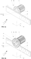
- Fig. 1a shows an embodiment of a part of a linear drive 1 in a perspective top view, which is not in accordance with the invention, but is helpful for understanding the linear drive according to the invention.
- the part of the linear drive 1 shown essentially comprises at least one primary part 5 designed as a reaction rail 5a with a return plate 5c, furthermore a secondary part 3, of which a first magnetic wheel 3a is shown, and a rotary drive 2, which is mechanically connected to the first magnetic wheel 3a.
- the first magnetic wheel 3a is equipped with magnets 4, in such a way that these magnets 4 generate a magnetic field that penetrates the reaction rail 5a and induce a number of eddy currents I 8 in this reaction rail 5a, which interact with the magnetic field, the magnetic field closing in a known manner via the return plate 5c of the primary part 5.
- the linear drive 1 is shown, which is also not in accordance with the invention but is helpful for understanding the linear drive according to the invention, wherein in addition to the first magnetic wheel 3a, at least one second magnetic wheel 3b of the secondary part 3 is shown, wherein the first and the second magnetic wheel 3a, 3b are arranged parallel to one another on a common axis 15 of the rotary drive 2, and wherein the first and the second magnetic wheel 3a, 3b are spaced apart from one another on this axis 15 in such a way that the at least one first reaction rail 5 can be arranged in a magnetically operative connection between them.
- the secondary part 3 and the first magnetic wheel 3a and the second magnetic wheel 3b are arranged horizontally, as in the Figures 4a to 4c is shown in more detail.
- the first and/or the second magnetic wheel 3a, 3b is/are equipped with magnets 4, in such a way that these magnets 4 generate the magnetic field B 6 between this first and this second magnetic wheel 3a, 3b, which magnetic field B 6 also penetrates the reaction rail 5a and thereby interacts with it.
- Fig. 1c shows additional possible arrangements of the magnets 4 on the first and second magnetic wheels 3a, 3b.
- the secondary part 3 is in Fig. 1c in a top view of the first magnetic wheel 3a and the second magnetic wheel 3b, whereby on one of the two the magnets 4a are designed as permanent magnets 4a and on the other as electromagnets 4b, optionally with a respective ferrite core 4c.
- Fig. 2a the secondary part 3 is shown in a simplified side view, whereby permanent magnets 4a facing each other are used, in Fig. 2b facing electromagnets 4b, in Fig. 2c facing permanent magnets 4a and electromagnets 4b. It is well known that for the purpose of expected magnetic field B 6 in Fig.
- adjacent magnets 4 on the respective first or second magnetic wheel 3a, 3b have a different polarity and also opposite magnets 4 on the one hand on the first magnetic wheel 3a and on the other hand on the second magnetic wheel 3b, provided that both are equipped with magnets 4 as in the Fig. 2a to 2c shown as an example.
- the magnetic field B 6 is shown using an example, which magnetic field B 6 is generated between the first and the second wheel 3a, 3b by the two associated magnets 4 with the polarities "N" and "S".
- the direction of the magnetic field B 6 changes to the respective adjacent magnet 4, although this is not explicitly shown here for the sake of simplicity; however, such magnet arrangements are sufficiently known in the technical field of electrical machines, so that such magnet arrangements can be assumed to be immediately and clearly known even without a more detailed pictorial representation than from the figures at hand.
- the rotary drive 2 sets the secondary part 3 in a rotating motion with the direction of rotation 7b, whereby the magnets 4 periodically rotate in and out of the area of the reaction rail 5a.
- FIG. 1a illustrates once again the mutually perpendicular current direction of the eddy currents I 8 to the magnetic field B 6 and the resulting force direction F 7a, which provides the translational drive.
- a necessary energy supply of the The power supply of the rotary drive 2 is not shown in detail here; an electrical supply, a hydraulic or a pneumatic supply or even a combination of two or three of the energy supply options mentioned can be provided for this power supply of the rotary drive 2.
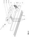
- Figure 3 it is shown that the secondary part 3 of the linear drive 1 with the rotary drive 2 is arranged on a support frame 11 of a drive platform 10 of a vehicle not shown in detail here, wherein a power supply 12, 12b of the linear drive 1 on the drive platform 10 can be provided via a number of current collectors 16 on busbars 9. Further examples of power supplies 12a or 12c are also indicated symbolically here; a more detailed explanation of the same does not appear necessary in view of expert knowledge.
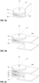
- Fig. 4a and 4b show examples of the linear drive 1 according to the invention, in which a horizontal arrangement of the secondary part 3 or the first and second magnetic wheels 3a, 3b is present.
- Fig. 4a For example, one leg of an L-profile beam 14a serves as a reaction rail and in Fig. 4b a leg of an H-profile beam 14b.
- a further force results during operation, namely a lifting force with a lifting force direction 13, which - as shown here - means a lifting of the first and second wheels 3a, 3b relative to the stationary L-profile support 14a or relative to the stationary H-profile support 14b.
- the Fig. 4c showed a further embodiment of the invention, in which, compared to the embodiment in Fig. 4b , a further second reaction rail 5b is shown, arranged parallel to the first reaction rail 5a, which is in operative connection with a further magnetic wheel 3c.
Landscapes
- Engineering & Computer Science (AREA)
- Power Engineering (AREA)
- Physics & Mathematics (AREA)
- Electromagnetism (AREA)
- Transportation (AREA)
- Mechanical Engineering (AREA)
- Chemical & Material Sciences (AREA)
- Combustion & Propulsion (AREA)
- Linear Motors (AREA)
- Dynamo-Electric Clutches, Dynamo-Electric Brakes (AREA)
Priority Applications (7)
| Application Number | Priority Date | Filing Date | Title |
|---|---|---|---|
| PL21171873.9T PL4087103T3 (pl) | 2021-05-03 | 2021-05-03 | Napęd liniowy |
| EP21171873.9A EP4087103B1 (de) | 2021-05-03 | 2021-05-03 | Linearantrieb |
| ES21171873T ES3024370T3 (en) | 2021-05-03 | 2021-05-03 | Linear drive |
| US18/558,255 US20240223059A1 (en) | 2021-05-03 | 2022-05-03 | Linear drive for track-guided means of land transportation or railway vehicles |
| PCT/EP2022/061769 WO2022233822A1 (en) | 2021-05-03 | 2022-05-03 | Linear drive |
| CN202280032184.2A CN117242683A (zh) | 2021-05-03 | 2022-05-03 | 线性驱动器 |
| CA3215140A CA3215140A1 (en) | 2021-05-03 | 2022-05-03 | Linear drive |
Applications Claiming Priority (1)
| Application Number | Priority Date | Filing Date | Title |
|---|---|---|---|
| EP21171873.9A EP4087103B1 (de) | 2021-05-03 | 2021-05-03 | Linearantrieb |
Publications (2)
| Publication Number | Publication Date |
|---|---|
| EP4087103A1 EP4087103A1 (de) | 2022-11-09 |
| EP4087103B1 true EP4087103B1 (de) | 2025-02-12 |
Family
ID=75787008
Family Applications (1)
| Application Number | Title | Priority Date | Filing Date |
|---|---|---|---|
| EP21171873.9A Active EP4087103B1 (de) | 2021-05-03 | 2021-05-03 | Linearantrieb |
Country Status (7)
| Country | Link |
|---|---|
| US (1) | US20240223059A1 (pl) |
| EP (1) | EP4087103B1 (pl) |
| CN (1) | CN117242683A (pl) |
| CA (1) | CA3215140A1 (pl) |
| ES (1) | ES3024370T3 (pl) |
| PL (1) | PL4087103T3 (pl) |
| WO (1) | WO2022233822A1 (pl) |
Families Citing this family (1)
| Publication number | Priority date | Publication date | Assignee | Title |
|---|---|---|---|---|
| US20240006934A1 (en) * | 2022-07-03 | 2024-01-04 | Kamil Podhola | Electromagnetic power transfer system |
Family Cites Families (13)
| Publication number | Priority date | Publication date | Assignee | Title |
|---|---|---|---|---|
| US3616762A (en) * | 1968-09-25 | 1971-11-02 | Linerail Manutention Par Moteu | Overhead conveyor system |
| DE3601963A1 (de) * | 1985-01-26 | 1986-07-31 | Kabushiki Kaisha Toshiba, Kawasaki, Kanagawa | Transportanordnung |
| JPH05336616A (ja) * | 1991-11-22 | 1993-12-17 | Aqueous Res:Kk | 車両用駆動装置及び二元推進式車両 |
| JPH09261805A (ja) * | 1996-03-19 | 1997-10-03 | Yaskawa Electric Corp | 磁気浮上アクチュエータ |
| CA2370416C (en) * | 2001-02-07 | 2010-01-26 | Denipro Ag | Conveyor system |
| US7204192B2 (en) * | 2001-07-02 | 2007-04-17 | Magna Force, Inc. | Apparatus, systems and methods for levitating and moving objects |
| US7002223B2 (en) * | 2001-07-27 | 2006-02-21 | Samsung Electronics Co., Ltd. | Semiconductor device having elevated source/drain |
| CA2457999A1 (en) * | 2004-02-17 | 2005-08-17 | Michel Paradis | Track belt guide wheels assembly |
| DE102008019319B4 (de) * | 2008-04-16 | 2011-07-07 | SEW-EURODRIVE GmbH & Co. KG, 76646 | Transportvorrichtung |
| US9126487B2 (en) * | 2013-03-15 | 2015-09-08 | Arx Pax, LLC | Hoverboard which generates magnetic lift to carry a person |
| CN106660463A (zh) * | 2014-06-11 | 2017-05-10 | 阿克斯帕克斯莱柏公司 | 用于磁性提升运载工具的推进和控制 |
| EP3107195A1 (de) * | 2015-06-16 | 2016-12-21 | InDriveTec AG | Linearmotorantriebssystem |
| DE102015226139A1 (de) * | 2015-12-21 | 2017-06-22 | Krones Ag | Lineares Transportsystem mit minimaler Transportteilung |
-
2021
- 2021-05-03 PL PL21171873.9T patent/PL4087103T3/pl unknown
- 2021-05-03 ES ES21171873T patent/ES3024370T3/es active Active
- 2021-05-03 EP EP21171873.9A patent/EP4087103B1/de active Active
-
2022
- 2022-05-03 CN CN202280032184.2A patent/CN117242683A/zh active Pending
- 2022-05-03 WO PCT/EP2022/061769 patent/WO2022233822A1/en not_active Ceased
- 2022-05-03 CA CA3215140A patent/CA3215140A1/en active Pending
- 2022-05-03 US US18/558,255 patent/US20240223059A1/en active Pending
Also Published As
| Publication number | Publication date |
|---|---|
| EP4087103A1 (de) | 2022-11-09 |
| US20240223059A1 (en) | 2024-07-04 |
| CA3215140A1 (en) | 2022-11-10 |
| PL4087103T3 (pl) | 2025-06-09 |
| WO2022233822A1 (en) | 2022-11-10 |
| ES3024370T3 (en) | 2025-06-04 |
| CN117242683A (zh) | 2023-12-15 |
Similar Documents
| Publication | Publication Date | Title |
|---|---|---|
| EP2150434B1 (de) | Fahrzeug mit einer wirbelstrombremse für ein spurgebundenes verkehrssystem und damit betriebenes verkehrssystem, insbesondere magnetschwebebahn | |
| EP2099640B1 (de) | Magnetschwebefahrzeug mit wenigstens einem magnetsystem | |
| EP0234543B1 (de) | Magnetkraftsystem für reibungsarmen Transport von Lasten | |
| EP1851408B1 (de) | Schiebetür mit einem magnetischen antriebssystem mit einem wegmesssystem | |
| EP0986490B1 (de) | Fahrsystem für ein magnetschwebefahrzeug | |
| WO2009074128A2 (de) | Magnetschwebebahn | |
| EP2485916A2 (de) | Beförderungssystem mit elektromagnetischer bremse | |
| DE102004013994A1 (de) | Magnetschwebebahn mit einer Wirbelstrombremse | |
| DE4222167C2 (de) | Magnetschwebebahn mit Supraleitung sowie dafür vorgesehene Stromzuleitungseinrichtung | |
| DE112017007591B4 (de) | Stromversorgungssystem einer Magnetschwebebahn | |
| DE2614883A1 (de) | Schienenfahrzeug mit magnetischer unterstuetzung | |
| WO2016128130A1 (de) | Schienengebundene magnetschwebebahn | |
| DE2438889A1 (de) | Fahrzeug mit linearsynchronmotor | |
| DE2710156C2 (de) | Magnetbahn | |
| DE2140103B1 (de) | Magnetische fuehrung einer schienengebundenen magnetschwebebahn | |
| EP4087103B1 (de) | Linearantrieb | |
| DE2339060C3 (de) | Magnetische Trag- und Vortriebseinrichtung fUr ein längs eines Fahrweges bewegbares Fahrzeug | |
| DE1206010B (de) | Anordnung fuer ein Zugsystem | |
| DE19718840C1 (de) | Antriebsmittel für eine Linearbewegung, insbesondere kontinuierliche Linearbewegung und Langstator-Linearmotor | |
| WO2009012743A1 (de) | Fahrzeug mit einer wirbelstrombremse für ein spurgebundenes verkehrssystem und damit betriebenes verkehrssystem, insbesondere magnetschwebebahn | |
| DE2256608C3 (de) | Mechanisch stellbare Weiche für eine magnetische Schebebahn | |
| DE2425940C2 (pl) | ||
| DE1563970B2 (de) | Gleisfahrzeug mit elektrischem antrieb durch zumindest einen linearen induktions motor | |
| DE29708026U1 (de) | Antriebsmittel für eine Linearbewegung, insbesondere kontinuierliche Linearbewegung und Langstator-Linearmotor | |
| DE2241790A1 (de) | Magnetische schwebebahn, bei der eine weiche mit magnetischer fuehrung vorgesehen ist |
Legal Events
| Date | Code | Title | Description |
|---|---|---|---|
| STAA | Information on the status of an ep patent application or granted ep patent |
Free format text: STATUS: EXAMINATION IS IN PROGRESS |
|
| PUAI | Public reference made under article 153(3) epc to a published international application that has entered the european phase |
Free format text: ORIGINAL CODE: 0009012 |
|
| 17P | Request for examination filed |
Effective date: 20210503 |
|
| AK | Designated contracting states |
Kind code of ref document: A1 Designated state(s): AL AT BE BG CH CY CZ DE DK EE ES FI FR GB GR HR HU IE IS IT LI LT LU LV MC MK MT NL NO PL PT RO RS SE SI SK SM TR |
|
| RBV | Designated contracting states (corrected) |
Designated state(s): AL AT BE BG CH CY CZ DE DK EE ES FI FR GB GR HR HU IE IS IT LI LT LU LV MC MK MT NL NO PL PT RO RS SE SI SK SM TR |
|
| RIN1 | Information on inventor provided before grant (corrected) |
Inventor name: VINZENS, MARTIN Inventor name: JULEN, ERIC |
|
| RIN1 | Information on inventor provided before grant (corrected) |
Inventor name: VINZENS, MARTIN Inventor name: JULEN, ERIC |
|
| TPAC | Observations filed by third parties |
Free format text: ORIGINAL CODE: EPIDOSNTIPA |
|
| RIC1 | Information provided on ipc code assigned before grant |
Ipc: B60L 13/03 20060101ALI20241004BHEP Ipc: B60L 13/10 20060101ALI20241004BHEP Ipc: B60L 13/00 20060101ALI20241004BHEP Ipc: H02K 49/04 20060101AFI20241004BHEP |
|
| GRAP | Despatch of communication of intention to grant a patent |
Free format text: ORIGINAL CODE: EPIDOSNIGR1 |
|
| STAA | Information on the status of an ep patent application or granted ep patent |
Free format text: STATUS: GRANT OF PATENT IS INTENDED |
|
| INTG | Intention to grant announced |
Effective date: 20241127 |
|
| GRAS | Grant fee paid |
Free format text: ORIGINAL CODE: EPIDOSNIGR3 |
|
| GRAA | (expected) grant |
Free format text: ORIGINAL CODE: 0009210 |
|
| STAA | Information on the status of an ep patent application or granted ep patent |
Free format text: STATUS: THE PATENT HAS BEEN GRANTED |
|
| AK | Designated contracting states |
Kind code of ref document: B1 Designated state(s): AL AT BE BG CH CY CZ DE DK EE ES FI FR GB GR HR HU IE IS IT LI LT LU LV MC MK MT NL NO PL PT RO RS SE SI SK SM TR |
|
| REG | Reference to a national code |
Ref country code: GB Ref legal event code: FG4D Free format text: NOT ENGLISH |
|
| REG | Reference to a national code |
Ref country code: CH Ref legal event code: EP |
|
| REG | Reference to a national code |
Ref country code: DE Ref legal event code: R096 Ref document number: 502021006596 Country of ref document: DE |
|
| REG | Reference to a national code |
Ref country code: IE Ref legal event code: FG4D Free format text: LANGUAGE OF EP DOCUMENT: GERMAN |
|
| REG | Reference to a national code |
Ref country code: NL Ref legal event code: FP |
|
| PGFP | Annual fee paid to national office [announced via postgrant information from national office to epo] |
Ref country code: NL Payment date: 20250404 Year of fee payment: 5 |
|
| REG | Reference to a national code |
Ref country code: ES Ref legal event code: FG2A Ref document number: 3024370 Country of ref document: ES Kind code of ref document: T3 Effective date: 20250604 |
|
| PG25 | Lapsed in a contracting state [announced via postgrant information from national office to epo] |
Ref country code: RS Free format text: LAPSE BECAUSE OF FAILURE TO SUBMIT A TRANSLATION OF THE DESCRIPTION OR TO PAY THE FEE WITHIN THE PRESCRIBED TIME-LIMIT Effective date: 20250512 |
|
| PG25 | Lapsed in a contracting state [announced via postgrant information from national office to epo] |
Ref country code: FI Free format text: LAPSE BECAUSE OF FAILURE TO SUBMIT A TRANSLATION OF THE DESCRIPTION OR TO PAY THE FEE WITHIN THE PRESCRIBED TIME-LIMIT Effective date: 20250212 |
|
| PGFP | Annual fee paid to national office [announced via postgrant information from national office to epo] |
Ref country code: PL Payment date: 20250409 Year of fee payment: 5 Ref country code: DE Payment date: 20250423 Year of fee payment: 5 |
|
| PGFP | Annual fee paid to national office [announced via postgrant information from national office to epo] |
Ref country code: GB Payment date: 20250520 Year of fee payment: 5 Ref country code: ES Payment date: 20250602 Year of fee payment: 5 |
|
| REG | Reference to a national code |
Ref country code: LT Ref legal event code: MG9D |
|
| PG25 | Lapsed in a contracting state [announced via postgrant information from national office to epo] |
Ref country code: NO Free format text: LAPSE BECAUSE OF FAILURE TO SUBMIT A TRANSLATION OF THE DESCRIPTION OR TO PAY THE FEE WITHIN THE PRESCRIBED TIME-LIMIT Effective date: 20250512 Ref country code: IS Free format text: LAPSE BECAUSE OF FAILURE TO SUBMIT A TRANSLATION OF THE DESCRIPTION OR TO PAY THE FEE WITHIN THE PRESCRIBED TIME-LIMIT Effective date: 20250612 |
|
| PGFP | Annual fee paid to national office [announced via postgrant information from national office to epo] |
Ref country code: IT Payment date: 20250509 Year of fee payment: 5 |
|
| PG25 | Lapsed in a contracting state [announced via postgrant information from national office to epo] |
Ref country code: HR Free format text: LAPSE BECAUSE OF FAILURE TO SUBMIT A TRANSLATION OF THE DESCRIPTION OR TO PAY THE FEE WITHIN THE PRESCRIBED TIME-LIMIT Effective date: 20250212 |
|
| PG25 | Lapsed in a contracting state [announced via postgrant information from national office to epo] |
Ref country code: LV Free format text: LAPSE BECAUSE OF FAILURE TO SUBMIT A TRANSLATION OF THE DESCRIPTION OR TO PAY THE FEE WITHIN THE PRESCRIBED TIME-LIMIT Effective date: 20250212 Ref country code: PT Free format text: LAPSE BECAUSE OF FAILURE TO SUBMIT A TRANSLATION OF THE DESCRIPTION OR TO PAY THE FEE WITHIN THE PRESCRIBED TIME-LIMIT Effective date: 20250612 |
|
| PGFP | Annual fee paid to national office [announced via postgrant information from national office to epo] |
Ref country code: FR Payment date: 20250528 Year of fee payment: 5 |
|
| PG25 | Lapsed in a contracting state [announced via postgrant information from national office to epo] |
Ref country code: BG Free format text: LAPSE BECAUSE OF FAILURE TO SUBMIT A TRANSLATION OF THE DESCRIPTION OR TO PAY THE FEE WITHIN THE PRESCRIBED TIME-LIMIT Effective date: 20250212 Ref country code: GR Free format text: LAPSE BECAUSE OF FAILURE TO SUBMIT A TRANSLATION OF THE DESCRIPTION OR TO PAY THE FEE WITHIN THE PRESCRIBED TIME-LIMIT Effective date: 20250513 |
|
| PGFP | Annual fee paid to national office [announced via postgrant information from national office to epo] |
Ref country code: CH Payment date: 20250601 Year of fee payment: 5 |
|
| PGFP | Annual fee paid to national office [announced via postgrant information from national office to epo] |
Ref country code: AT Payment date: 20250721 Year of fee payment: 5 |
|
| PG25 | Lapsed in a contracting state [announced via postgrant information from national office to epo] |
Ref country code: SE Free format text: LAPSE BECAUSE OF FAILURE TO SUBMIT A TRANSLATION OF THE DESCRIPTION OR TO PAY THE FEE WITHIN THE PRESCRIBED TIME-LIMIT Effective date: 20250212 |
|
| PG25 | Lapsed in a contracting state [announced via postgrant information from national office to epo] |
Ref country code: SM Free format text: LAPSE BECAUSE OF FAILURE TO SUBMIT A TRANSLATION OF THE DESCRIPTION OR TO PAY THE FEE WITHIN THE PRESCRIBED TIME-LIMIT Effective date: 20250212 |
|
| PG25 | Lapsed in a contracting state [announced via postgrant information from national office to epo] |
Ref country code: DK Free format text: LAPSE BECAUSE OF FAILURE TO SUBMIT A TRANSLATION OF THE DESCRIPTION OR TO PAY THE FEE WITHIN THE PRESCRIBED TIME-LIMIT Effective date: 20250212 |
|
| PG25 | Lapsed in a contracting state [announced via postgrant information from national office to epo] |
Ref country code: CZ Free format text: LAPSE BECAUSE OF FAILURE TO SUBMIT A TRANSLATION OF THE DESCRIPTION OR TO PAY THE FEE WITHIN THE PRESCRIBED TIME-LIMIT Effective date: 20250212 Ref country code: EE Free format text: LAPSE BECAUSE OF FAILURE TO SUBMIT A TRANSLATION OF THE DESCRIPTION OR TO PAY THE FEE WITHIN THE PRESCRIBED TIME-LIMIT Effective date: 20250212 |
|
| PG25 | Lapsed in a contracting state [announced via postgrant information from national office to epo] |
Ref country code: RO Free format text: LAPSE BECAUSE OF FAILURE TO SUBMIT A TRANSLATION OF THE DESCRIPTION OR TO PAY THE FEE WITHIN THE PRESCRIBED TIME-LIMIT Effective date: 20250212 |
|
| PG25 | Lapsed in a contracting state [announced via postgrant information from national office to epo] |
Ref country code: SK Free format text: LAPSE BECAUSE OF FAILURE TO SUBMIT A TRANSLATION OF THE DESCRIPTION OR TO PAY THE FEE WITHIN THE PRESCRIBED TIME-LIMIT Effective date: 20250212 |