EP4087019A1 - Battery module and battery pack comprising same - Google Patents
Battery module and battery pack comprising same Download PDFInfo
- Publication number
- EP4087019A1 EP4087019A1 EP21846536.7A EP21846536A EP4087019A1 EP 4087019 A1 EP4087019 A1 EP 4087019A1 EP 21846536 A EP21846536 A EP 21846536A EP 4087019 A1 EP4087019 A1 EP 4087019A1
- Authority
- EP
- European Patent Office
- Prior art keywords
- battery
- cooling block
- cell stack
- battery module
- battery cell
- Prior art date
- Legal status (The legal status is an assumption and is not a legal conclusion. Google has not performed a legal analysis and makes no representation as to the accuracy of the status listed.)
- Pending
Links
Images


Classifications
-
- H—ELECTRICITY
- H01—ELECTRIC ELEMENTS
- H01M—PROCESSES OR MEANS, e.g. BATTERIES, FOR THE DIRECT CONVERSION OF CHEMICAL ENERGY INTO ELECTRICAL ENERGY
- H01M10/00—Secondary cells; Manufacture thereof
- H01M10/42—Methods or arrangements for servicing or maintenance of secondary cells or secondary half-cells
- H01M10/48—Accumulators combined with arrangements for measuring, testing or indicating the condition of cells, e.g. the level or density of the electrolyte
- H01M10/482—Accumulators combined with arrangements for measuring, testing or indicating the condition of cells, e.g. the level or density of the electrolyte for several batteries or cells simultaneously or sequentially
-
- H—ELECTRICITY
- H01—ELECTRIC ELEMENTS
- H01M—PROCESSES OR MEANS, e.g. BATTERIES, FOR THE DIRECT CONVERSION OF CHEMICAL ENERGY INTO ELECTRICAL ENERGY
- H01M10/00—Secondary cells; Manufacture thereof
- H01M10/60—Heating or cooling; Temperature control
- H01M10/61—Types of temperature control
- H01M10/613—Cooling or keeping cold
-
- H—ELECTRICITY
- H01—ELECTRIC ELEMENTS
- H01M—PROCESSES OR MEANS, e.g. BATTERIES, FOR THE DIRECT CONVERSION OF CHEMICAL ENERGY INTO ELECTRICAL ENERGY
- H01M10/00—Secondary cells; Manufacture thereof
- H01M10/60—Heating or cooling; Temperature control
- H01M10/61—Types of temperature control
- H01M10/617—Types of temperature control for achieving uniformity or desired distribution of temperature
-
- H—ELECTRICITY
- H01—ELECTRIC ELEMENTS
- H01M—PROCESSES OR MEANS, e.g. BATTERIES, FOR THE DIRECT CONVERSION OF CHEMICAL ENERGY INTO ELECTRICAL ENERGY
- H01M10/00—Secondary cells; Manufacture thereof
- H01M10/60—Heating or cooling; Temperature control
- H01M10/65—Means for temperature control structurally associated with the cells
- H01M10/653—Means for temperature control structurally associated with the cells characterised by electrically insulating or thermally conductive materials
-
- H—ELECTRICITY
- H01—ELECTRIC ELEMENTS
- H01M—PROCESSES OR MEANS, e.g. BATTERIES, FOR THE DIRECT CONVERSION OF CHEMICAL ENERGY INTO ELECTRICAL ENERGY
- H01M10/00—Secondary cells; Manufacture thereof
- H01M10/60—Heating or cooling; Temperature control
- H01M10/65—Means for temperature control structurally associated with the cells
- H01M10/655—Solid structures for heat exchange or heat conduction
- H01M10/6553—Terminals or leads
-
- H—ELECTRICITY
- H01—ELECTRIC ELEMENTS
- H01M—PROCESSES OR MEANS, e.g. BATTERIES, FOR THE DIRECT CONVERSION OF CHEMICAL ENERGY INTO ELECTRICAL ENERGY
- H01M50/00—Constructional details or processes of manufacture of the non-active parts of electrochemical cells other than fuel cells, e.g. hybrid cells
- H01M50/20—Mountings; Secondary casings or frames; Racks, modules or packs; Suspension devices; Shock absorbers; Transport or carrying devices; Holders
- H01M50/204—Racks, modules or packs for multiple batteries or multiple cells
-
- H—ELECTRICITY
- H01—ELECTRIC ELEMENTS
- H01M—PROCESSES OR MEANS, e.g. BATTERIES, FOR THE DIRECT CONVERSION OF CHEMICAL ENERGY INTO ELECTRICAL ENERGY
- H01M50/00—Constructional details or processes of manufacture of the non-active parts of electrochemical cells other than fuel cells, e.g. hybrid cells
- H01M50/20—Mountings; Secondary casings or frames; Racks, modules or packs; Suspension devices; Shock absorbers; Transport or carrying devices; Holders
- H01M50/233—Mountings; Secondary casings or frames; Racks, modules or packs; Suspension devices; Shock absorbers; Transport or carrying devices; Holders characterised by physical properties of casings or racks, e.g. dimensions
- H01M50/24—Mountings; Secondary casings or frames; Racks, modules or packs; Suspension devices; Shock absorbers; Transport or carrying devices; Holders characterised by physical properties of casings or racks, e.g. dimensions adapted for protecting batteries from their environment, e.g. from corrosion
-
- H—ELECTRICITY
- H01—ELECTRIC ELEMENTS
- H01M—PROCESSES OR MEANS, e.g. BATTERIES, FOR THE DIRECT CONVERSION OF CHEMICAL ENERGY INTO ELECTRICAL ENERGY
- H01M50/00—Constructional details or processes of manufacture of the non-active parts of electrochemical cells other than fuel cells, e.g. hybrid cells
- H01M50/50—Current conducting connections for cells or batteries
- H01M50/502—Interconnectors for connecting terminals of adjacent batteries; Interconnectors for connecting cells outside a battery casing
- H01M50/507—Interconnectors for connecting terminals of adjacent batteries; Interconnectors for connecting cells outside a battery casing comprising an arrangement of two or more busbars within a container structure, e.g. busbar modules
-
- H—ELECTRICITY
- H01—ELECTRIC ELEMENTS
- H01M—PROCESSES OR MEANS, e.g. BATTERIES, FOR THE DIRECT CONVERSION OF CHEMICAL ENERGY INTO ELECTRICAL ENERGY
- H01M2220/00—Batteries for particular applications
- H01M2220/20—Batteries in motive systems, e.g. vehicle, ship, plane
-
- Y—GENERAL TAGGING OF NEW TECHNOLOGICAL DEVELOPMENTS; GENERAL TAGGING OF CROSS-SECTIONAL TECHNOLOGIES SPANNING OVER SEVERAL SECTIONS OF THE IPC; TECHNICAL SUBJECTS COVERED BY FORMER USPC CROSS-REFERENCE ART COLLECTIONS [XRACs] AND DIGESTS
- Y02—TECHNOLOGIES OR APPLICATIONS FOR MITIGATION OR ADAPTATION AGAINST CLIMATE CHANGE
- Y02E—REDUCTION OF GREENHOUSE GAS [GHG] EMISSIONS, RELATED TO ENERGY GENERATION, TRANSMISSION OR DISTRIBUTION
- Y02E60/00—Enabling technologies; Technologies with a potential or indirect contribution to GHG emissions mitigation
- Y02E60/10—Energy storage using batteries
Definitions
- the present disclosure relates to a battery module and a battery pack including the same, and more particularly, to a battery module having improved cooling performance, and a battery pack including the same.
- a secondary battery has attracted much attention as an energy source in various products such as a mobile device and an electric vehicle.
- the secondary battery is a potent energy resource that can replace the use of existing products using fossil fuels, and is in the spotlight as an environment-friendly energy source because it does not generate by-products due to energy use.
- a method of configuring a battery module composed of at least one battery cell and then adding other components to at least one battery module to configure a battery pack is common.
- the battery module may include a battery cell stack in which a plurality of battery cells are stacked, a frame for housing the battery cell stack, and end plates for covering the front and rear surfaces of the battery cell stack.
- Fig. 1 is an exploded perspective view of a conventional battery module.
- Fig. 2 is a cross-sectional view showing a section A-A of Fig. 1 .
- the conventional battery module may include a battery cell stack 10 formed by stacking a plurality of battery cells 11,amoduleframe 20 for housing the battery cell stack 10,and electrode leads 12 formed to protrude at both ends of the plurality of battery cells 11 constituting the battery cell stack 10.
- the battery module may include a busbar frame 41that is equipped with a busbar 40 coupled to the electrode lead 12 and covers the front and rear surfaces of the battery cell stack 10, an insulating cover 50 that covers the busbar frame 41 from the outside, an end plate that covers the insulating cover 50 from the outside, and a thermally conductive resin layer 60 that is formed between the battery cell stack 10 and the module frame bottom portion21.
- a thermally conductive resin layer 60 was formed between the module frame bottom portion 21 and the lower side surface of the battery cell stack 10, so that heat generated from the battery cell stack 10 was transferred to the outside.
- a separate cooling component is not disposed in the portion where the electrode lead 12 and the busbar 40, actually generating the largest amount of heat in the battery cell, are disposed, the temperature of the portion where the electrode lead 12 and the busbar 40 are located rises locally, so that the temperature deviation between the internal portions of the battery module increases and thereby, the overall performance of the battery module may be deteriorated.
- a battery module comprising: a battery cell stack in which a plurality of battery cells are stacked; a module frame for housing the battery cell stack; and an end plate for covering the front and rear surfaces of the battery cell stack, wherein electrode leads, each protruding from the plurality of battery cells, are formed on the front and rear surfaces of the battery cell stack, and a cooling block is disposed between the electrode leads and the end plate.
- An insulating cover is formed between the end plate and the electrode leads, and the cooling block may be inserted and coupled to the opening of the insulating cover.
- a protrusion is formed on the inner side periphery of the opening, a groove portion is formed around the cooling block, and the protrusion is inserted into the groove portion so that the cooling block can be coupled to the opening.
- the insulating cover may be injected by inserting the cooling block into the opening.
- Busbars mounted on a busbar frame are disposed between the cooling block and the battery cell stack, and a cooling pad in contact with the cooling block and the busbars may be attached between the cooling block and the busbars.
- the cooling pad is formed of a viscous material, and can adhere closely to the surface of the busbar and the busbar frame.
- a cooling adhesive may be applied to the cooling block surface of the cooling block facing the end plate.
- a thermally conductive resin layer may be formed between the battery cell stack and the module frame bottom portion.
- the cooling block may include an insulating or thermally conductive material.
- abattery pack comprising the battery module.
- a battery module and a battery pack including the same can minimize a temperature deviation inside the battery module and improve the overall cooling performance of the battery module, by disposing cooling components, such as a cooling block, a cooling pad, and a cooling adhesive, at the portion where the electrode lead and the busbar are located.
- cooling components such as a cooling block, a cooling pad, and a cooling adhesive
- terms such as first, second, and the like may be used to describe various components, and the components are not limited by the terms. The terms are used only to discriminate one component from another component.
- Fig. 3 is an exploded perspective view of a battery module according to one embodiment of the present disclosure.
- the battery module includes a battery cell stack 100 in which a plurality of battery cells are stacked, a module frame 200 for housing the battery cell stack 100, and end plates300 for covering the front and rear surfaces of the battery cell stack 100. Electrode leads 120, each protruding from the plurality of battery cells 110, are formed on the front and rear surfaces of the battery cell stack 100, and a cooling block 700 may be disposed between the electrode leads 120 and the end plate 300.
- the battery cell 110 is a secondary battery, and may be configured into a pouch-type secondary battery.
- a battery cell 110 may be composed of a plurality of battery cells, and the plurality of battery cells may be mutually stacked so as to be electrically connected to each other, thereby forming the battery cell stack 100.
- Each of the plurality of battery cells may include an electrode assembly, a cell case, and an electrode lead 120 protruding from the electrode assembly.
- the module frame 200 houses the battery cell stack 100.
- the module frame 200 can be formed of upper, lower, left and right surfaces, so as to cover the four surfaces of upper, lower, left and right of the battery cell stack 100.
- the battery cell stack 100 housed inside the module frame 200 can be physically protected through the module frame 200.
- a busbar frame 400 is formed so as to cover the front and rear surfaces of the battery cell stack 100, and can be connected with electrode leads formed to extrude from the plurality of battery cells 110 at the front and rear surfaces of the battery cell stack 100. More specifically, electrode leads extended through the busbar frame 400 are coupled to the plurality of busbars 410 mounted on the busbar frame 400, so that the battery cells 110 and the busbars 410 can be electrically connected.
- the end plates 300 are respectively formed on the outside of the busbar frame 400 on the basis of the battery cell stack 100,and can be formed so as to cover the battery cell stack 100 and the busbar frame 400.
- the end plates 300 can protect the busbar frame 400, the battery cell stack 100, and various electrical equipment connected thereto from external impacts, and at the same time, guide the electrical connection between the battery cell stack 100 and an external power.
- An insulating cover 500 can be inserted between the end plate 300 and the busbar frame 400.
- the insulating cover 500 can cut off the electrical connection between the busbar frame 400 and the outside to ensure the insulation performance of the battery module.
- a thermally conductive resin layer 600 can be formed on the module frame bottom portion 210.
- the battery cell stack 100 is located on the upper side of the thermally conductive resin layer 600, and the heat generated from the battery cell stack 100 can be transferred to the outside of the battery module.
- the thermally conductive resin layer 600 may be formed of a thermal resin.
- the thermally conductive resin layer 600 may be formed by a process in which a thermally conductive resin is injected through a plurality of injection holes formed on the module frame bottom portion 210 and then cured.
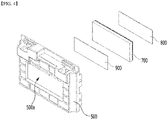
- Fig. 4 is a diagram showing the appearance of cooling components mounted on the insulating cover of Fig. 3 .
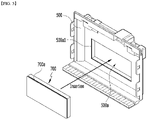
- Fig. 5 is a diagram showing a state in which the cooling block according to one embodiment of the present disclosure is coupled to the insulating cover.
- a cooling block is disposed between the electrode leads 120 and the end plate 300.
- an insulating cover 500 is formed between the end plate 300 and the electrode leads 120, and the cooling block 700 may be inserted and coupled to the insulating cover opening 500a formed on the insulating cover 500.
- the cooling block 700 includes an insulating or thermally conductive material to ensure insulation performance in the portion of the opening 500a of the insulating cover 500, and at the same time, can transfer the heat generated from the electrode leads 120 and the busbar 410 to the outside.
- the cooling block 700 may include aluminum, aluminum nitride, or alumina having insulation properties and thermal conductivity.
- components to carry out cooling are not arranged in the electrode leads and busbars, which generate the largest amount of heat in the battery module, and thus, the temperature of the portion in which the electrode lead and the busbar are located is locally increased, and the temperature deviation between the internal portions of the battery module may become larger. Further, the heat generated from the electrode leads and busbars is hard to be discharged to the outside, and the temperature of the battery module rises, and the performance of the battery module may be deteriorated due to the increase in temperature.
- the cooling block 700 is disposed atthe portion where the electrode leads 120 and the busbar 410 are disposed, so that the heat generated in the electrode lead 120 and the busbar 410 can be cooled. More specifically, the heat generated from the electrode leads 120 and the busbar 410 may be discharged to the outside through the end plate 300 via the cooling block 700.In addition to the heat transfer path through which the heat generated in the battery cell stack 100 is discharged to the lower side through the thermally conductive resin layer 600 located on the lower side of the existing battery cell stack 100 as described above, a route for discharging to the outside through the front and rear surfaces of the battery cell stack 100 is newly established, so that the heat transfer path may be diversified, and the cooling performance of the battery module can be further improved.
- a cooling pad 800 in contact with the cooling block 700 and the busbars 410 can be attached between the cooling block 700 and the busbars 410 mounted on the busbar frame 400.
- the cooling pad 800 is in direct contact with the busbar 410 and the electrode leads 120 coupled to the outer surface of the busbar 410, so that the heat generated from the busbar 410 and the electrode leads 120 can be transferred directly to the cooling block 700.
- the cooling pad 800 is formed of a viscous material and adheres closely to the surface of the busbar 410 and the busbar frame 400 in which irregularities are present, whereby the heat generated from the busbar 410 and the electrode leads 120 can reduce the interfacial resistance through surface contact and can be more efficiently transferred to the cooling block 700.
- the cooling adhesive 900 can be applied to the cooling block surface facing the end plate 300.
- the cooling adhesive 900 includes a heat transfer material, reduces the interface resistance between the end plate 300 and the cooling block 700, and efficiently discharge the heat transferred to the cooling block 700 to the outside through the end plate 300.
- the end plate 300 may include aluminum having excellent thermal conductivity.
- Fig. 5 shows a state in which the cooling block 700 is coupled to the insulating cover 500.
- the insulating cover 500 can be coupled with the cooling block 700 by inserting the cooling block 700 into the opening 500a.Thereby, the rigidity of the insulating cover 500 in which the opening 500a is formed can be obtained.
- a groove portion 700a is formed in the cooling block 700 according to this embodiment, a protrusion 500a1 is formed on the inner side periphery of the insulating cover opening 500a, and the protrusion 500a1 can be inserted into the groove portion 700a so that the cooling block 700 can be coupled to the opening. Thereby, the cohesion force between the cooling block 700 and the insulating cover 500 can be strengthened.
- the above-mentioned battery module can be included in the battery pack.
- the battery pack may have a structure in which one or more of the battery modules according to the embodiment of the present disclosure are gathered, and packed together with a battery management system (BMS) and a cooling device that control and manage battery's temperature, voltage, etc.
- BMS battery management system
- the battery pack can be applied to various devices.
- a device may be applied to a vehicle means such as an electric bicycle, an electric vehicle, or a hybrid vehicle, but the present disclosure is not limited thereto, and is applicable to various devices that can use a battery module, which also falls under the scope of the present disclosure.
Abstract
A battery module according to one embodiment of the present disclosure includes a battery cell stack in which a plurality of battery cells are stacked; a module frame for housing the battery cell stack; and an end plate for covering the front and rear surfaces of the battery cell stack, wherein an opening is formed between the module frame bottom portion and the end plate.
Description
- This application claims the benefit of
Korean Patent Application No. 10-2020-0091093 filed on July 22, 2020 - The present disclosure relates to a battery module and a battery pack including the same, and more particularly, to a battery module having improved cooling performance, and a battery pack including the same.
- A secondary battery has attracted much attention as an energy source in various products such as a mobile device and an electric vehicle. The secondary battery is a potent energy resource that can replace the use of existing products using fossil fuels, and is in the spotlight as an environment-friendly energy source because it does not generate by-products due to energy use.
- Recently, along with a continuous rise of the necessity for a large-capacity secondary battery structure, including the utilization of the secondary battery as an energy storage source, there is a growing demand for a battery pack of a multi-module structure which is an assembly of battery modules in which a plurality of secondary batteries are connected in series/parallel.
- Meanwhile, when a plurality of battery cells are connected in series/parallel to configure a battery pack, a method of configuring a battery module composed of at least one battery cell and then adding other components to at least one battery module to configure a battery pack is common.
- The battery module may include a battery cell stack in which a plurality of battery cells are stacked, a frame for housing the battery cell stack, and end plates for covering the front and rear surfaces of the battery cell stack.
-
Fig. 1 is an exploded perspective view of a conventional battery module.Fig. 2 is a cross-sectional view showing a section A-A ofFig. 1 . - Referring to
Figs. 1 and2 , the conventional battery module may include abattery cell stack 10 formed by stacking a plurality ofbattery cells 11,amoduleframe 20 for housing thebattery cell stack 10,and electrode leads 12 formed to protrude at both ends of the plurality ofbattery cells 11 constituting thebattery cell stack 10. - Further, the battery module may include a busbar frame 41that is equipped with a
busbar 40 coupled to theelectrode lead 12 and covers the front and rear surfaces of thebattery cell stack 10,aninsulating cover 50 that covers thebusbar frame 41 from the outside, an end plate that covers theinsulating cover 50 from the outside, and a thermallyconductive resin layer 60 that is formed between thebattery cell stack 10 and the module frame bottom portion21. - In relation to the cooling function of the battery module, conventionally, a thermally
conductive resin layer 60 was formed between the moduleframe bottom portion 21 and the lower side surface of thebattery cell stack 10, so that heat generated from thebattery cell stack 10 was transferred to the outside. However, since a separate cooling component is not disposed in the portion where the electrode lead 12 and thebusbar 40, actually generating the largest amount of heat in the battery cell, are disposed, the temperature of the portion where the electrode lead 12 and thebusbar 40 are located rises locally, so that the temperature deviation between the internal portions of the battery module increases and thereby, the overall performance of the battery module may be deteriorated. - It is an object of the present disclosure to provide a battery module that minimizes the temperature deviation between the internal portions of the battery module and lowers the temperature of the battery cell, thus improving cooling performance, and a battery pack including the same.
- The objects of the present disclosure are not limited to the aforementioned objects, and other objects which are not described herein should be clearly understood by those skilled in the art from the following detailed description.
- According to one embodiment of the present disclosure, there is provided a battery module comprising: a battery cell stack in which a plurality of battery cells are stacked; a module frame for housing the battery cell stack; and an end plate for covering the front and rear surfaces of the battery cell stack, wherein electrode leads, each protruding from the plurality of battery cells, are formed on the front and rear surfaces of the battery cell stack, and a cooling block is disposed between the electrode leads and the end plate.
- An insulating cover is formed between the end plate and the electrode leads, and the cooling block may be inserted and coupled to the opening of the insulating cover.
- A protrusion is formed on the inner side periphery of the opening, a groove portion is formed around the cooling block, and the protrusion is inserted into the groove portion so that the cooling block can be coupled to the opening.
- The insulating cover may be injected by inserting the cooling block into the opening.
- Busbars mounted on a busbar frame are disposed between the cooling block and the battery cell stack, and a cooling pad in contact with the cooling block and the busbars may be attached between the cooling block and the busbars.
- The cooling pad is formed of a viscous material, and can adhere closely to the surface of the busbar and the busbar frame.
- A cooling adhesive may be applied to the cooling block surface of the cooling block facing the end plate.
- A thermally conductive resin layer may be formed between the battery cell stack and the module frame bottom portion.
- The cooling block may include an insulating or thermally conductive material.
- According to another embodiment of the present disclosure, there is provided abattery pack comprising the battery module.
- A battery module and a battery pack including the same according to embodiments of the present disclosure invention can minimizea temperature deviation inside the battery module and improve the overall cooling performance of the battery module, by disposing cooling components, such as a cooling block, a cooling pad, and a cooling adhesive, at the portion where the electrode lead and the busbar are located.
- The effects of the present disclosure are not limited to the effects mentioned above and additional other effects not described above will be clearly understood from the description of the appended claims by those skilled in the art.
-
-
Fig. 1 is an exploded perspective view of a conventional battery module; -
Fig. 2 is a cross-sectional view showing a section A-A ofFig. 1 andFig. 3 ; -
Fig. 3 is an exploded perspective view of a battery module according to one embodiment of the present disclosure; -
Fig. 4 is a diagram showing the appearance of cooling components mounted on the insulating cover ofFig. 3 ; and -
Fig. 5 is a diagram showing a state in which the cooling block according to one embodiment of the present disclosure is coupled to the insulating cover. - It should be appreciated that the exemplary embodiments, which will be described below, are illustratively described to assist in the understand the present disclosure, and the present disclosure can be variously modified to be carried out differently from the exemplary embodiments described herein. However, in the description of the present disclosure, the specific descriptions and illustrations of publicly known functions or constituent elements will be omitted when it is determined that the specific descriptions and illustrations may unnecessarily obscure the subject matter of the present disclosure. In addition, in order to help understand the present disclosure, the accompanying drawings are not illustrated based on actual scales, but parts of the constituent elements may be exaggerated in size.
- As used herein, terms such as first, second, and the like may be used to describe various components, and the components are not limited by the terms. The terms are used only to discriminate one component from another component.
- Further, the terms used herein are used only to describe specific exemplary embodiments, and are not intended to limit the scope of the present disclosure. A singular expression includes a plural expression unless they have definitely opposite meanings in the context. It should be understood that the terms "comprise", "include", and "have" as used herein are intended to designate the presence of stated features, numbers, steps, movements, constitutional elements, partsor combinations thereof, but it should be understood that they do not preclude a possibility of existence or addition of one or more other features, numbers, steps, movements, constitutional elements, parts or combinations thereof.
- Hereinafter, a battery module according to one embodiment of the present disclosure will be described with reference to
Figs. 2 and3 . -
Fig. 3 is an exploded perspective view of a battery module according to one embodiment of the present disclosure. - Referring to
Figs. 2 and3 , the battery module according to one embodiment of the present disclosure includes abattery cell stack 100 in which a plurality of battery cells are stacked, amodule frame 200 for housing thebattery cell stack 100, and end plates300 for covering the front and rear surfaces of thebattery cell stack 100. Electrode leads 120, each protruding from the plurality ofbattery cells 110, are formed on the front and rear surfaces of thebattery cell stack 100, and acooling block 700 may be disposed between the electrode leads 120 and theend plate 300. - The
battery cell 110 is a secondary battery, and may be configured into a pouch-type secondary battery. Such abattery cell 110 may be composed of a plurality of battery cells, and the plurality of battery cells may be mutually stacked so as to be electrically connected to each other, thereby forming thebattery cell stack 100. Each of the plurality of battery cells may include an electrode assembly, a cell case, and anelectrode lead 120 protruding from the electrode assembly. - The
module frame 200 houses the battery cell stack 100.Themodule frame 200 can be formed of upper, lower, left and right surfaces, so as to cover the four surfaces of upper, lower, left and right of thebattery cell stack 100. Thebattery cell stack 100 housed inside themodule frame 200 can be physically protected through themodule frame 200. - A
busbar frame 400 is formed so as to cover the front and rear surfaces of thebattery cell stack 100, and can be connected with electrode leads formed to extrude from the plurality ofbattery cells 110 at the front and rear surfaces of thebattery cell stack 100. More specifically, electrode leads extended through thebusbar frame 400 are coupled to the plurality ofbusbars 410 mounted on thebusbar frame 400, so that thebattery cells 110 and thebusbars 410 can be electrically connected. - The
end plates 300 are respectively formed on the outside of thebusbar frame 400 on the basis of thebattery cell stack 100,and can be formed so as to cover thebattery cell stack 100 and thebusbar frame 400. Theend plates 300 can protect thebusbar frame 400, thebattery cell stack 100, and various electrical equipment connected thereto from external impacts, and at the same time, guide the electrical connection between thebattery cell stack 100 and an external power. - An
insulating cover 500 can be inserted between theend plate 300 and the busbar frame 400.Theinsulating cover 500 can cut off the electrical connection between thebusbar frame 400 and the outside to ensure the insulation performance of the battery module. - A thermally
conductive resin layer 600 can be formed on the module frame bottom portion 210.Thebattery cell stack 100 is located on the upper side of the thermallyconductive resin layer 600, and the heat generated from thebattery cell stack 100 can be transferred to the outside of the battery module. According to this embodiment, the thermallyconductive resin layer 600 may be formed of a thermal resin. The thermallyconductive resin layer 600 may be formed by a process in which a thermally conductive resin is injected through a plurality of injection holes formed on the moduleframe bottom portion 210 and then cured. - Below, cooling components formed in the insulating cover according to one embodiment of the present disclosure will be described with reference to
Figs. 3 to 5 . -
Fig. 4 is a diagram showing the appearance of cooling components mounted on the insulating cover ofFig. 3 .Fig. 5 is a diagram showing a state in which the cooling block according to one embodiment of the present disclosure is coupled to the insulating cover. - Referring to
Figs. 3 to 5 , in the battery module according to one embodiment of the present disclosure, a cooling block is disposed between the electrode leads 120 and the end plate 300.More specifically, an insulatingcover 500 is formed between theend plate 300 and the electrode leads 120, and thecooling block 700 may be inserted and coupled to the insulatingcover opening 500a formed on the insulatingcover 500. - The
cooling block 700 includes an insulating or thermally conductive material to ensure insulation performance in the portion of theopening 500a of the insulatingcover 500, and at the same time, can transfer the heat generated from the electrode leads 120 and thebusbar 410 to the outside.According to this embodiment, thecooling block 700 may include aluminum, aluminum nitride, or alumina having insulation properties and thermal conductivity. - Conventionally, components to carry out cooling are not arranged in the electrode leads and busbars, which generate the largest amount of heat in the battery module, and thus, the temperature of the portion in which the electrode lead and the busbar are located is locally increased, and the temperature deviation between the internal portions of the battery module may become larger. Further, the heat generated from the electrode leads and busbars is hard to be discharged to the outside, and the temperature of the battery module rises, and the performance of the battery module may be deteriorated due to the increase in temperature.
- Thus, according to one embodiment of the present disclosure, the
cooling block 700 is disposed atthe portion where the electrode leads 120 and thebusbar 410 are disposed, so that the heat generated in theelectrode lead 120 and thebusbar 410 can be cooled. More specifically, the heat generated from the electrode leads 120 and thebusbar 410 may be discharged to the outside through theend plate 300 via the cooling block 700.In addition to the heat transfer path through which the heat generated in thebattery cell stack 100 is discharged to the lower side through the thermallyconductive resin layer 600 located on the lower side of the existingbattery cell stack 100 as described above, a route for discharging to the outside through the front and rear surfaces of thebattery cell stack 100 is newly established, so that the heat transfer path may be diversified, and the cooling performance of the battery module can be further improved. - According to the present embodiment, a
cooling pad 800 in contact with thecooling block 700 and thebusbars 410 can be attached between the coolingblock 700 and thebusbars 410 mounted on the busbar frame 400.Thecooling pad 800 is in direct contact with thebusbar 410 and the electrode leads 120 coupled to the outer surface of thebusbar 410, so that the heat generated from thebusbar 410 and the electrode leads 120 can be transferred directly to thecooling block 700. - The
cooling pad 800 is formed of a viscous material and adheres closely to the surface of thebusbar 410 and thebusbar frame 400 in which irregularities are present, whereby the heat generated from thebusbar 410 and the electrode leads 120 can reduce the interfacial resistance through surface contact and can be more efficiently transferred to thecooling block 700. - According to the present embodiment, the cooling adhesive 900 can be applied to the cooling block surface facing the end plate 300.The cooling adhesive 900 includes a heat transfer material, reduces the interface resistance between the
end plate 300 and thecooling block 700, and efficiently discharge the heat transferred to thecooling block 700 to the outside through theend plate 300. According to the present embodiment, theend plate 300 may include aluminum having excellent thermal conductivity. -
Fig. 5 shows a state in which thecooling block 700 is coupled to the insulating cover 500.The insulatingcover 500 can be coupled with thecooling block 700 by inserting thecooling block 700 into the opening 500a.Thereby, the rigidity of the insulatingcover 500 in which theopening 500a is formed can be obtained. As shown inFig. 5 , agroove portion 700a is formed in thecooling block 700 according to this embodiment, a protrusion 500a1 is formed on the inner side periphery of the insulatingcover opening 500a, and the protrusion 500a1 can be inserted into thegroove portion 700a so that thecooling block 700 can be coupled to the opening. Thereby, the cohesion force between the coolingblock 700 and the insulatingcover 500 can be strengthened. - The above-mentioned battery module can be included in the battery pack. The battery pack may have a structure in which one or more of the battery modules according to the embodiment of the present disclosure are gathered, and packed together with a battery management system (BMS) and a cooling device that control and manage battery's temperature, voltage, etc.
- The battery pack can be applied to various devices. Such a device may be applied to a vehicle means such as an electric bicycle, an electric vehicle, or a hybrid vehicle, but the present disclosure is not limited thereto, and is applicable to various devices that can use a battery module, which also falls under the scope of the present disclosure.
- Although the invention has been shown and described with reference to the preferred embodiments, the scope of the present disclosure is not limited thereto, and numerous other modifications and embodiments can be devised by those skilled in the art that will fall within the spirit and scope of the principles of the invention described in the appended claims. Further, these modified embodiments should not be understood individually from the technical spirit or perspective of the present disclosure.
-
- 100: battery cell stack
- 110: battery cell
- 120: electrode lead
- 200: module frame
- 210: module frame bottom portion
- 300: end plate
- 400: busbar frame
- 410: busbar
- 420: connector
- 500: insulating cover
- 500a: insulating cover opening
- 500a1: protrusion
- 600: thermally conductive resin layer
- 700: cooling block
- 700a: groove portion
- 800: cooling pad
- 900: cooling adhesive
Claims (10)
- A battery module comprising:a battery cell stack in which a plurality of battery cells are stacked;a module frame for housing the battery cell stack; andan end plate for covering the front and rear surfaces of the battery cell stack,wherein electrode leads, each protruding from the plurality of battery cells, are formed on the front and rear surfaces of the battery cell stack, anda cooling block is disposed between the electrode leads and the end plate.
- The battery module of claim 1, wherein:an insulating cover is formed between the end plate and the electrode leads, andthe cooling block is inserted and coupled to an opening of the insulating cover.
- The battery module of claim 2, wherein:
a protrusion is formed on the inner side periphery of the opening, a groove portion is formed around the cooling block, and the protrusion is inserted into the groove portion so that the cooling block is coupled to the opening. - The battery module of claim 2, wherein:
the insulating cover is coupled with the cooling block by inserting the cooling block into the opening. - The battery module of claim 1, wherein:busbars mounted on a busbar frame are disposed between the cooling block and the battery cell stack, anda cooling pad in contact with the cooling block and the busbars is attached between the cooling block and the busbars.
- The battery module of claim 5, wherein:
the cooling pad is formed of a viscous material and adheres closely to the surface of the busbar and the busbar frame. - The battery module of claim 1, wherein:
a cooling adhesive is applied to surface of the cooling block facing the end plate. - The battery module of claim 1, wherein:
a thermally conductive resin layer is formed between the battery cell stack and a module frame bottom portion. - The battery module of claim 1, wherein:
the cooling block comprises an insulating or thermally conductive material. - A battery pack comprising the battery module of claim 1.
Applications Claiming Priority (2)
| Application Number | Priority Date | Filing Date | Title |
|---|---|---|---|
| KR1020200091093A KR20220012045A (en) | 2020-07-22 | 2020-07-22 | Battery module and battery pack including the same |
| PCT/KR2021/009427 WO2022019653A1 (en) | 2020-07-22 | 2021-07-21 | Battery module and battery pack comprising same |
Publications (1)
| Publication Number | Publication Date |
|---|---|
| EP4087019A1 true EP4087019A1 (en) | 2022-11-09 |
Family
ID=79729645
Family Applications (1)
| Application Number | Title | Priority Date | Filing Date |
|---|---|---|---|
| EP21846536.7A Pending EP4087019A1 (en) | 2020-07-22 | 2021-07-21 | Battery module and battery pack comprising same |
Country Status (6)
| Country | Link |
|---|---|
| US (1) | US20230112676A1 (en) |
| EP (1) | EP4087019A1 (en) |
| JP (1) | JP2023514122A (en) |
| KR (1) | KR20220012045A (en) |
| CN (1) | CN115244763A (en) |
| WO (1) | WO2022019653A1 (en) |
Families Citing this family (1)
| Publication number | Priority date | Publication date | Assignee | Title |
|---|---|---|---|---|
| KR20230134376A (en) * | 2022-03-14 | 2023-09-21 | 에스케이온 주식회사 | Battery module |
Family Cites Families (5)
| Publication number | Priority date | Publication date | Assignee | Title |
|---|---|---|---|---|
| KR101217608B1 (en) * | 2011-05-31 | 2013-01-02 | 주식회사 이아이지 | Battery cassette and battery module including the same |
| US9614208B2 (en) * | 2011-10-10 | 2017-04-04 | Samsung Sdi Co., Ltd. | Battery pack with degassing cover and plate thereon |
| JP5916500B2 (en) * | 2012-04-27 | 2016-05-11 | オートモーティブエナジーサプライ株式会社 | Assembled battery |
| KR101821376B1 (en) * | 2014-04-03 | 2018-01-23 | 주식회사 엘지화학 | Battery module array having 2-cell with center frame type module |
| KR102253511B1 (en) * | 2018-01-23 | 2021-05-18 | 주식회사 엘지화학 | Gap Filler |
-
2020
- 2020-07-22 KR KR1020200091093A patent/KR20220012045A/en active Search and Examination
-
2021
- 2021-07-21 CN CN202180018496.3A patent/CN115244763A/en active Pending
- 2021-07-21 US US17/913,734 patent/US20230112676A1/en active Pending
- 2021-07-21 WO PCT/KR2021/009427 patent/WO2022019653A1/en unknown
- 2021-07-21 JP JP2022547134A patent/JP2023514122A/en active Pending
- 2021-07-21 EP EP21846536.7A patent/EP4087019A1/en active Pending
Also Published As
| Publication number | Publication date |
|---|---|
| CN115244763A (en) | 2022-10-25 |
| US20230112676A1 (en) | 2023-04-13 |
| WO2022019653A1 (en) | 2022-01-27 |
| JP2023514122A (en) | 2023-04-05 |
| KR20220012045A (en) | 2022-02-03 |
Similar Documents
| Publication | Publication Date | Title |
|---|---|---|
| EP3671895B1 (en) | Battery module, battery pack comprising battery module and vehicle comprising battery pack | |
| EP3817090B1 (en) | Battery module | |
| CN110710051B (en) | Battery pack | |
| KR102523098B1 (en) | Secondary Battery and Battery Module Having the Same | |
| EP3866252A1 (en) | Battery module and battery pack comprising same | |
| EP3694022A2 (en) | Battery module | |
| KR20200002349A (en) | Battery Module Having Unit Body | |
| EP3958379A1 (en) | Battery module and battery pack comprising same | |
| EP4087019A1 (en) | Battery module and battery pack comprising same | |
| CN116018714A (en) | Battery module and battery pack including the same | |
| EP3952005A1 (en) | Battery module and battery pack including same | |
| KR20210060243A (en) | Battery module and manufacturing method thereof | |
| EP4027443A1 (en) | Battery module and battery pack comprising same | |
| EP4099488A1 (en) | Battery module and battery pack including same | |
| EP3916893A1 (en) | Battery module and battery pack including same | |
| EP3940868A1 (en) | Battery module and battery pack including same | |
| EP3792992B1 (en) | Battery module comprising module housing | |
| KR20210092563A (en) | Battery module and battery pack including the same | |
| EP4060800A1 (en) | Battery module and battery pack including same | |
| US20220407138A1 (en) | Battery Module and Manufacturing Method Thereof | |
| EP3996190A1 (en) | Battery pack and device including same | |
| US20220352589A1 (en) | Battery module and battery pack including the same | |
| KR20210092564A (en) | Battery module and manufacturing method thereof | |
| KR20210056079A (en) | Battery pack and device including the same | |
| KR20210069426A (en) | Battery module and battery pack including the same |
Legal Events
| Date | Code | Title | Description |
|---|---|---|---|
| STAA | Information on the status of an ep patent application or granted ep patent |
Free format text: STATUS: THE INTERNATIONAL PUBLICATION HAS BEEN MADE |
|
| PUAI | Public reference made under article 153(3) epc to a published international application that has entered the european phase |
Free format text: ORIGINAL CODE: 0009012 |
|
| STAA | Information on the status of an ep patent application or granted ep patent |
Free format text: STATUS: REQUEST FOR EXAMINATION WAS MADE |
|
| 17P | Request for examination filed |
Effective date: 20220802 |
|
| AK | Designated contracting states |
Kind code of ref document: A1 Designated state(s): AL AT BE BG CH CY CZ DE DK EE ES FI FR GB GR HR HU IE IS IT LI LT LU LV MC MK MT NL NO PL PT RO RS SE SI SK SM TR |
|
| DAV | Request for validation of the european patent (deleted) | ||
| DAX | Request for extension of the european patent (deleted) |