EP4086987A1 - Electrode for fuel cell having high durability, method for manufacturing same, and membrane-electrode assembly comprising same - Google Patents
Electrode for fuel cell having high durability, method for manufacturing same, and membrane-electrode assembly comprising same Download PDFInfo
- Publication number
- EP4086987A1 EP4086987A1 EP20910671.5A EP20910671A EP4086987A1 EP 4086987 A1 EP4086987 A1 EP 4086987A1 EP 20910671 A EP20910671 A EP 20910671A EP 4086987 A1 EP4086987 A1 EP 4086987A1
- Authority
- EP
- European Patent Office
- Prior art keywords
- catalyst
- electrode
- mixed solution
- ionomer
- dispersion
- Prior art date
- Legal status (The legal status is an assumption and is not a legal conclusion. Google has not performed a legal analysis and makes no representation as to the accuracy of the status listed.)
- Pending
Links
Images


Classifications
-
- H—ELECTRICITY
- H01—ELECTRIC ELEMENTS
- H01M—PROCESSES OR MEANS, e.g. BATTERIES, FOR THE DIRECT CONVERSION OF CHEMICAL ENERGY INTO ELECTRICAL ENERGY
- H01M4/00—Electrodes
- H01M4/86—Inert electrodes with catalytic activity, e.g. for fuel cells
- H01M4/8663—Selection of inactive substances as ingredients for catalytic active masses, e.g. binders, fillers
-
- H—ELECTRICITY
- H01—ELECTRIC ELEMENTS
- H01M—PROCESSES OR MEANS, e.g. BATTERIES, FOR THE DIRECT CONVERSION OF CHEMICAL ENERGY INTO ELECTRICAL ENERGY
- H01M4/00—Electrodes
- H01M4/86—Inert electrodes with catalytic activity, e.g. for fuel cells
- H01M4/8663—Selection of inactive substances as ingredients for catalytic active masses, e.g. binders, fillers
- H01M4/8668—Binders
-
- H—ELECTRICITY
- H01—ELECTRIC ELEMENTS
- H01M—PROCESSES OR MEANS, e.g. BATTERIES, FOR THE DIRECT CONVERSION OF CHEMICAL ENERGY INTO ELECTRICAL ENERGY
- H01M4/00—Electrodes
- H01M4/86—Inert electrodes with catalytic activity, e.g. for fuel cells
- H01M4/88—Processes of manufacture
- H01M4/8825—Methods for deposition of the catalytic active composition
- H01M4/8828—Coating with slurry or ink
-
- H—ELECTRICITY
- H01—ELECTRIC ELEMENTS
- H01M—PROCESSES OR MEANS, e.g. BATTERIES, FOR THE DIRECT CONVERSION OF CHEMICAL ENERGY INTO ELECTRICAL ENERGY
- H01M4/00—Electrodes
- H01M4/86—Inert electrodes with catalytic activity, e.g. for fuel cells
- H01M4/90—Selection of catalytic material
- H01M4/92—Metals of platinum group
- H01M4/921—Alloys or mixtures with metallic elements
-
- H—ELECTRICITY
- H01—ELECTRIC ELEMENTS
- H01M—PROCESSES OR MEANS, e.g. BATTERIES, FOR THE DIRECT CONVERSION OF CHEMICAL ENERGY INTO ELECTRICAL ENERGY
- H01M4/00—Electrodes
- H01M4/86—Inert electrodes with catalytic activity, e.g. for fuel cells
- H01M4/90—Selection of catalytic material
- H01M4/92—Metals of platinum group
- H01M4/925—Metals of platinum group supported on carriers, e.g. powder carriers
- H01M4/926—Metals of platinum group supported on carriers, e.g. powder carriers on carbon or graphite
-
- H—ELECTRICITY
- H01—ELECTRIC ELEMENTS
- H01M—PROCESSES OR MEANS, e.g. BATTERIES, FOR THE DIRECT CONVERSION OF CHEMICAL ENERGY INTO ELECTRICAL ENERGY
- H01M8/00—Fuel cells; Manufacture thereof
- H01M8/10—Fuel cells with solid electrolytes
- H01M8/1004—Fuel cells with solid electrolytes characterised by membrane-electrode assemblies [MEA]
-
- H—ELECTRICITY
- H01—ELECTRIC ELEMENTS
- H01M—PROCESSES OR MEANS, e.g. BATTERIES, FOR THE DIRECT CONVERSION OF CHEMICAL ENERGY INTO ELECTRICAL ENERGY
- H01M8/00—Fuel cells; Manufacture thereof
- H01M8/10—Fuel cells with solid electrolytes
- H01M8/1016—Fuel cells with solid electrolytes characterised by the electrolyte material
- H01M8/1018—Polymeric electrolyte materials
-
- H—ELECTRICITY
- H01—ELECTRIC ELEMENTS
- H01M—PROCESSES OR MEANS, e.g. BATTERIES, FOR THE DIRECT CONVERSION OF CHEMICAL ENERGY INTO ELECTRICAL ENERGY
- H01M8/00—Fuel cells; Manufacture thereof
- H01M8/10—Fuel cells with solid electrolytes
- H01M2008/1095—Fuel cells with polymeric electrolytes
-
- H—ELECTRICITY
- H01—ELECTRIC ELEMENTS
- H01M—PROCESSES OR MEANS, e.g. BATTERIES, FOR THE DIRECT CONVERSION OF CHEMICAL ENERGY INTO ELECTRICAL ENERGY
- H01M2300/00—Electrolytes
- H01M2300/0017—Non-aqueous electrolytes
- H01M2300/0065—Solid electrolytes
- H01M2300/0082—Organic polymers
-
- H—ELECTRICITY
- H01—ELECTRIC ELEMENTS
- H01M—PROCESSES OR MEANS, e.g. BATTERIES, FOR THE DIRECT CONVERSION OF CHEMICAL ENERGY INTO ELECTRICAL ENERGY
- H01M2300/00—Electrolytes
- H01M2300/0088—Composites
- H01M2300/0094—Composites in the form of layered products, e.g. coatings
-
- Y—GENERAL TAGGING OF NEW TECHNOLOGICAL DEVELOPMENTS; GENERAL TAGGING OF CROSS-SECTIONAL TECHNOLOGIES SPANNING OVER SEVERAL SECTIONS OF THE IPC; TECHNICAL SUBJECTS COVERED BY FORMER USPC CROSS-REFERENCE ART COLLECTIONS [XRACs] AND DIGESTS
- Y02—TECHNOLOGIES OR APPLICATIONS FOR MITIGATION OR ADAPTATION AGAINST CLIMATE CHANGE
- Y02E—REDUCTION OF GREENHOUSE GAS [GHG] EMISSIONS, RELATED TO ENERGY GENERATION, TRANSMISSION OR DISTRIBUTION
- Y02E60/00—Enabling technologies; Technologies with a potential or indirect contribution to GHG emissions mitigation
- Y02E60/30—Hydrogen technology
- Y02E60/50—Fuel cells
Definitions
- the present disclosure relates to an electrode for fuel cells, a method of producing the same, and a membrane-electrode assembly including the same. More particularly, the present disclosure relates to an electrode for fuel cells having high durability by preventing catalyst deterioration due to agglomeration, precipitation, dissolution, and/or migration of metal catalyst particles, a method of producing the same, and a membrane-electrode assembly including the same.
- a polymer electrolyte membrane fuel cell which generates electricity using a stacked structure of unit cells, each including a membrane-electrode assembly (MEA) and a separator (also referred to as a "bipolar plate”), is drawing attention as a next-generation energy source capable of replacing fossil fuels due to the high energy efficiency and environmental friendliness thereof.
- MEA membrane-electrode assembly
- separator also referred to as a "bipolar plate
- the membrane-electrode assembly generally includes an anode (also referred to as a "fuel electrode”), a cathode (also referred to as an “air electrode”), and a polymer electrolyte membrane (PEM) interposed therebetween.
- anode also referred to as a "fuel electrode”
- cathode also referred to as an “air electrode”
- PEM polymer electrolyte membrane
- Platinum or platinum alloys having high catalytic activity and high corrosion resistance, are used as a metal catalyst for forming an electrode for a fuel cell.
- a catalyst formed by dispersing metal catalyst particles on the surface of an electrically conductive support e.g., carbon, metal oxide or C 3 N 4 .
- FIG. 1 is a schematic diagram showing a conventional electrode for fuel cells before and after a voltage cycling test (VC test).
- a conventional electrode for fuel cells includes a catalyst 10 and an ionomer layer 20 disposed on the catalyst 10.
- the catalyst 10 includes a support 11 and a plurality of metal catalyst particles 12 supported on the support 111.
- agglomeration (11a), precipitation, dissolution, and/or migration (11b) of the metal catalyst is caused by high-voltage and highly acidic environments, which accelerates the degradation of the catalyst 10. Therefore, it is very important to prevent deterioration of the catalyst upon long-term operation of the fuel cell to increase the durability and lifespan of the fuel cell.
- the carbon shell is disadvantageous because it reduces the active area of the catalyst and interferes with the transfer of substances such as gas and/or water and thus decreases the output performance of the fuel cell.
- the carbon shell is not economical because it requires a separate process for introducing the carbon shell.
- the present disclosure relates to an electrode for fuel cells that is capable of preventing problems caused by limitations and disadvantages of the related technology as described above, a method of producing the same, and a membrane-electrode assembly including the same.
- an electrode for a fuel cell including: a catalyst including a support and a plurality of metal catalyst particles supported on the support; and an ionomer layer coated on at least a part of the catalyst, wherein the ionomer layer includes an ionomer and a chelating agent.
- the ionomer layer may be bonded to the catalyst using only a physical bond, not a chemical bond.
- the ionomer may be a fluorine-based ionomer or a hydrocarbon-based ionomer.
- the chelating agent may be dimercaprol, phthalocyanine, M-phthalocyanine (wherein M is Cu, Co, Fe, or Mo), penicillamine, succimer, deferoxamine, EDTA, EGTA, Prussian blue, vitamin B-12, ⁇ -lipoic acid, ethylenediamine, triethylamine, phenanthroline, desferrioxamine, deferiprone, or a mixture of two or more thereof.
- the chelating agent may be dimercaprol, penicillamine, succimer, ⁇ -lipoic acid, triethylamine, deferiprone, or a mixture of two or more thereof.
- the chelating agent may include at least one S atom.
- the chelating agent including at least one S atom may be dimercaprol, penicillamine, succimer, ⁇ -lipoic acid, or a mixture of two or more thereof.
- the chelating agent may include at least two S atoms.
- the chelating agent including at least two S atoms may be dimercaprol, succimer, ⁇ -lipoic acid, or a mixture of two or more thereof.
- a method of producing an electrode for a fuel cell including: preparing an electrode slurry containing a catalyst, an ionomer, a chelating agent, and a dispersion medium; coating a film or a membrane with the electrode slurry to form a slurry layer; and removing the dispersion medium from the slurry layer.
- the electrode slurry may contain 0.01 to 10 parts by weight of the chelating agent based on 100 parts by weight of the ionomer.
- the preparing the electrode slurry may include: preparing a mixture containing the ionomer and the chelating agent; preparing a catalyst dispersion containing the catalyst and the dispersion medium; mixing the mixture with the catalyst dispersion to obtain a mixed solution; and dispersing the mixed solution using a homogenizer, a high-pressure disperser, a ball mill, a powder mixer, or a resonant acoustic mixer.
- the preparing the catalyst dispersion may include: wetting the catalyst with water; and dispersing the catalyst wetted with water in the dispersion medium.
- the preparing the electrode slurry may include: preparing a mixture containing the ionomer and the chelating agent; preparing a catalyst dispersion containing the catalyst; mixing the mixture with the catalyst dispersion to obtain a mixed solution; dispersing the mixed solution using a homogenizer, a high-pressure disperser, a ball mill, a powder mixer, or a resonance acoustic mixer; drying the dispersed mixed solution to obtain a solid; heat-treating the solid; and dispersing the heat-treated solid in the dispersion medium using a homogenizer, a high-pressure disperser, a ball mill, a powder mixer, or a resonance acoustic mixer.
- the catalyst dispersion may be prepared by dispersing the catalyst in water.
- the preparing the electrode slurry may include: mixing an ionomer dispersion containing the ionomer with a catalyst dispersion containing the catalyst to obtain a first mixed solution; dispersing the first mixed solution using a homogenizer, a high-pressure disperser, a ball mill, a powder mixer, or a resonance acoustic mixer; drying the dispersed first mixed solution to obtain a solid; heat-treating the solid; mixing the heat-treated solid with the dispersion medium to obtain a second mixed solution; preparing a mixture containing the ionomer and the chelating agent; mixing the mixture with the second mixed solution to obtain a third mixed solution; and dispersing the third mixed solution using a homogenizer, a high-pressure disperser, a ball mill, a powder mixer, or a resonance acoustic mixer.
- the catalyst dispersion may contain water as a dispersion medium.
- the preparing the electrode slurry may include: preparing a mixture containing the ionomer and the chelating agent; preparing a catalyst dispersion containing the catalyst; mixing a part of the mixture with the catalyst dispersion to obtain a first mixed solution; dispersing the first mixed solution using a homogenizer, a high-pressure disperser, a ball mill, a powder mixer, or a resonance acoustic mixer; drying the dispersed first mixed solution to obtain a solid; heat-treating the solid; mixing the heat-treated solid and the remainder of the mixture with the dispersion medium to obtain a second mixed solution; and dispersing the second mixed solution using a homogenizer, a high-pressure disperser, a ball mill, a powder mixer, or a resonance acoustic mixer.
- the catalyst dispersion may be prepared by dispersing the catalyst in water.
- a membrane-electrode assembly including an anode, a cathode, and a polymer electrolyte membrane interposed between the anode and the cathode, wherein at least one of the anode and cathode is the electrode described above.
- an electrode for a fuel cell is formed using an electrode slurry containing a chelating agent, so that the ionomer layer containing the chelating agent in addition to the ionomer covers at least a part of the catalyst.
- the ionomer layer of the present disclosure captures the metal ions obtained from the metal catalyst particles and allows the metal ions to return to the original place thereof when the environment changes, thereby inhibiting the agglomeration and precipitation of the metal catalyst particles and preventing the dissolution and migration of the metal catalyst.
- the durability of an electrode for a fuel cell and a membrane-electrode assembly including the same can be improved, and thus the lifespan of the fuel cell can be prolonged by preventing catalyst deterioration due to agglomeration, deposition, elution, and/or movement of metal catalyst particles.
- FIG. 2 is a schematic diagram showing an electrode 100 for a fuel cell according to an embodiment of the present disclosure.
- the electrode 100 for a fuel cell of the present disclosure includes a catalyst 110 and an ionomer layer 120 coated on at least a part of the catalyst 110.
- the catalyst 110 includes a support 111 and a plurality of metal catalyst particles 112 supported on the support 111.
- the support 111 may be (i) a carbon-based support, (ii) a porous inorganic oxide support such as zirconia, alumina, titania, silica, and ceria, or (iii) a zeolite support.
- the carbon-based support may be graphite, super P, carbon fiber, carbon sheet, carbon black, Ketjen black, Denka black, acetylene black, carbon nanotubes (CNT), carbon spheres, carbon ribbon, fullerene, active carbon, carbon nanowires, carbon nanoballs, carbon nanohorns, carbon nanocages, carbon nanorings, ordered nano-/mesoporous carbon, carbon aerogel, mesoporous carbon, graphene, stabilized carbon, or a combination of two or more thereof.
- CNT carbon nanotubes
- the metal catalyst particles 112 may be platinum (Pt) particles or platinum-based alloy particles.
- the platinum-based alloy may be Pt-Pd, Pt-Mn, Pt-Sn, Pt-Mo, Pt-W, Pt-Ru, Pt-Ru-W, Pt-Ru-Ni, Pt-Ru-Mo, Pt-Ru-Rh-Ni, Pt-Ru-Sn-W, Pt-Ru-Ir-Ni, Pt-Co, Pt-Co-Mn, Pt-Co-Ni, Pt-Co-Fe, Pt-Co-Ir, Pt-Co-S, Pt-Co-P, Pt-Fe, Pt-Fe-Ir, Pt-Fe-Ir, Pt-Fe-S, Pt-Fe-P, Pt-Au-Co, Pt-Au-Fe, Pt-Au-Ni, Pt-Ni, Pt-Ni-Ir, Pt-Cr, or Pt-Cr-Ir.
- the ionomer layer 120 of the present disclosure includes an ionomer and a chelating agent.
- the ionomer layer 120 is bonded to the catalyst 110 only through a physical bond rather than a chemical bond, thereby preventing deterioration of the catalytic activity of the catalyst 110.
- the ionomer of the ionomer layer 120 serves to transfer cations, and also serves as a binder for improving adhesion between the catalyst 110 and the polymer electrolyte membrane (PEM).
- PEM polymer electrolyte membrane
- the ionomer may have at least one ion-conducting group selected from the group consisting of a sulfonic acid group, a carboxyl group, a boronic acid group, a phosphoric acid group, an imide group, a sulfonimide group, a sulfonamide group, and a sulfonic fluoride group.
- the ionomer may be a fluorine-based ionomer such as poly(perfluorosulfonic acid) or poly(perfluorocarboxylic acid).
- the ionomer may be a hydrocarbon-based polymer such as sulfonated polyimide (S-PI), sulfonated polyarylethersulfone (S-PAES), sulfonated polyetheretherketone (SPEEK), sulfonated polybenzimidazole (SPBI), sulfonated polysulfone (S-PSU), sulfonated polystyrene (S-PS), sulfonated polyphosphazene, sulfonated polyquinoxaline, sulfonated polyketone, sulfonated polyphenylene oxide, sulfonated polyether sulfone, sulfonated polyether ketone, sulfonated polyphenylene sulfone, sulfonated polyphenylene sulfide, sulfonated polyphenylene sulfide sulfone, sulfonated polyphenylene
- the chelating agent of the ionomer layer 120 captures the metal ions derived from the metal catalyst particles 112 during long-term operation of the fuel cell, and allows the metal ions to return to the original place thereof when the environment changes, thereby inhibiting the agglomeration and precipitation of the metal catalyst particles 112 and preventing the dissolution and migration of the metal catalyst.
- FIG. 3 is a schematic diagram showing an electrode for a fuel cell according to an embodiment of the present disclosure after a voltage cycling test and shows that metal ions (Pt 2+ ) derived from the metal catalyst particles 111b form a coordination bond with a chelating agent (dimercaprol), thereby minimizing the agglomeration 111a of the metal catalyst particles and returning the metal ions (Pt 2+ ) to the original metal catalyst particles 111b upon environmental changes, thus preventing deterioration of the catalyst 110 due to dissolution and/or movement of the metal catalyst.
- a chelating agent dimercaprol
- the chelating agent of the present disclosure is dimercaprol, phthalocyanine, M-phthalocyanine (where M is Cu, Co, Fe, or Mo), penicillamine, Succimer, deferoxamine, EDTA, EGTA, Prussian blue, vitamin B-12, ⁇ -lipoic acid, ethylenediamine, triethylamine, phenanthroline, desferrioxamine, deferiprone, or a mixture of two or more thereof, more preferably dimercaprol, penicillamine, succimer, ⁇ -lipoic acid, triethylamine, deferiprone, or a mixture of two or more thereof.
- the chelating agent of the present disclosure includes at least one S atom, and may be, for example, dimercaprol, penicillamine, succimer, ⁇ -lipoic acid, or a mixture of two or more thereof.
- the chelating agent of the present disclosure contains at least two S atoms, and may be, for example, dimercaprol, succimer, ⁇ -lipoic acid, or a mixture of two or more thereof.
- the S atom binds well with metal ions derived from the metal catalyst particles 111b and has stronger binding force therewith, thereby effectively capturing the metal ions and increasing the durability of the electrode 100.
- dimercaprol forms a chelate bond well enough to be biochemically used as an antidote for heavy metals.
- the method of the present disclosure includes: (i) preparing an electrode slurry containing a catalyst, an ionomer, a chelating agent and a dispersion medium; (ii) coating a film or a membrane with the electrode slurry to form a slurry layer; and (iii) removing the dispersion medium from the slurry layer.
- the dispersion medium may be water, a hydrophilic solvent, an organic solvent, or a mixture of two or more thereof.
- the hydrophilic solvent may be a compound containing, as a main chain, a linear or branched saturated or unsaturated hydrocarbon having 1 to 12 carbon atoms, and having at least one functional group selected from the group consisting of alcohols, isopropyl alcohol, ketones, aldehydes, carbonates, carboxylates, carboxylic acids, ethers, and amides.
- the organic solvent may be N-methylpyrrolidone (NMP), dimethylsulfoxide (DMSO), tetrahydrofuran (THF), dimethylacetamide (DMAc), or a mixture of two or more thereof, but is not limited thereto.
- NMP N-methylpyrrolidone
- DMSO dimethylsulfoxide
- THF tetrahydrofuran
- DMAc dimethylacetamide
- the dispersion medium of the electrode slurry may be ethanol, distilled water, isopropyl alcohol, normal propyl alcohol, butanol, or a mixture of two or more thereof, but is not limited thereto.
- the electrode slurry may contain 0.01 to 10 parts by weight of the chelating agent based on 100 parts by weight of the ionomer.
- the content of the chelating agent is less than 0.01 parts by weight, a satisfactory effect of preventing catalyst deterioration cannot be obtained.
- the content of the chelating agent exceeds 10 parts by weight, the activity of the metal catalyst may be inhibited, resulting in deterioration of the performance of the fuel cell.
- An electrode is formed on at least one surface of the polymer electrolyte membrane (PEM) through decal transfer or direct coating using the electrode slurry.
- PEM polymer electrolyte membrane
- a release film is coated with the electrode slurry to form a slurry layer, the dispersion medium is removed from the slurry layer through a drying process to form an electrode, hot-pressing is performed in the state in which the release film and the polymer electrolyte membrane (PEM) are stacked such that the release film contacts the polymer electrolyte membrane (PEM), and then the release film is removed.
- PEM polymer electrolyte membrane
- a mask film having an electrode window is stacked on one surface of the polymer electrolyte membrane (PEM), the electrode slurry is coated on one surface of the polymer electrolyte membrane (PEM) to form a slurry layer, the dispersion medium is removed from the slurry layer to form an electrode, and then the mask film is removed.
- PEM polymer electrolyte membrane
- the electrode slurry of the present disclosure may be prepared through any of various methods.
- a first method of preparing the electrode slurry may include (i) preparing a mixture containing the ionomer and the chelating agent, (ii) preparing a catalyst dispersion containing the catalyst and the dispersion medium, (iii) mixing the mixture with the catalyst dispersion to obtain a mixed solution, and (iv) dispersing the mixed solution using a homogenizer, a high-pressure disperser, a ball mill, a powder mixer, or a resonant acoustic mixer.
- the mixture containing the ionomer and the chelating agent may be obtained by adding the chelating agent to the ionomer dispersion, followed by mixing to homogeneity.
- the ionomer dispersion may be a commercially available fluorine-based ionomer dispersion (e.g., Nafion dispersion).
- the catalyst dispersion may be obtained by wetting the catalyst with water and dispersing the catalyst in the dispersion medium for the electrode slurry according to the present disclosure described above.
- the reason for wetting the catalyst with water is that the catalyst may ignite if brought into contact with alcohol or the like first, due to the high reactivity of the catalyst.
- a second method of preparing the electrode slurry may include (i) preparing a mixture containing the ionomer and the chelating agent, (ii) preparing a catalyst dispersion containing the catalyst, (iii) mixing the mixture with the catalyst dispersion to obtain a mixed solution, (iv) dispersing the dispersed mixed solution using a homogenizer, a high-pressure disperser, a ball mill, a powder mixer, or a resonance acoustic mixer, (v) drying the dispersed mixed solution to obtain a solid, (vi) heat-treating the solid, and (vii) dispersing the heat-treated solid in the dispersion medium using a homogenizer, a high-pressure disperser, a ball mill, a powder mixer, or a resonance acoustic mixer.
- the mixture containing the ionomer and the chelating agent may be obtained by adding the chelating agent to the ionomer dispersion, followed by mixing to homogeneity.
- the ionomer dispersion may be a commercially available fluorine-based ionomer dispersion (e.g., Nafion dispersion).
- the catalyst dispersion may be prepared by dispersing the catalyst in water.
- the reason for using water as the dispersion medium is that the catalyst may ignite if brought into contact with alcohol or the like first due to the high reactivity of the catalyst.
- the drying may be performed at 60 to 90°C for 5 to 10 hours, and the heat treatment may be performed at 90 to 150°C for 1 to 3 hours.
- a third method of preparing the electrode slurry may include (i) mixing an ionomer dispersion containing the ionomer with a catalyst dispersion containing the catalyst to obtain a first mixed solution, (ii) dispersing the first mixed solution using a homogenizer, a high-pressure disperser, a ball mill, a powder mixer, or a resonance acoustic mixer, (iii) drying the dispersed first mixed solution to obtain a solid, (iv) heat-treating the solid, (v) mixing the heat-treated solid with the dispersion medium to obtain a second mixed solution, (vi) preparing a mixture containing the ionomer and the chelating agent, (vii) mixing the mixture with the second mixed solution to obtain a third mixed solution, and (viii) dispersing the third mixed solution using a homogenizer, a high-pressure disperser, a ball mill, a powder mixer, or a resonance acoustic mixer.
- the ionomer dispersion may be a commercially available fluorine-based ionomer dispersion (e.g., Nafion dispersion).
- the catalyst dispersion may contain water as a dispersion medium.
- the drying may be performed at 60 to 90°C for 5 to 10 hours, and the heat treatment may be performed at 90 to 150°C for 1 to 3 hours.
- a fourth method of preparing the electrode slurry may include (i) preparing a mixture containing the ionomer and the chelating agent, (ii) preparing a catalyst dispersion containing the catalyst, (iii) mixing a part of the mixture with the catalyst dispersion to obtain a first mixed solution, (iv) dispersing the first mixed solution using a homogenizer, a high-pressure disperser, a ball mill, a powder mixer, or a resonance acoustic mixer, (v) drying the dispersed first mixed solution to obtain a solid, (vi) heat-treating the solid, (vii) mixing the heat-treated solid and the remainder of the mixture with the dispersion medium to obtain a second mixed solution, and (viii) dispersing the second mixed solution using a homogenizer, a high-pressure disperser, a ball mill, a powder mixer, or a resonance acoustic mixer.
- the mixture containing the ionomer and the chelating agent may be obtained by adding the chelating agent to the ionomer dispersion, followed by mixing to homogeneity.
- the ionomer dispersion may be a commercially available fluorine-based ionomer dispersion (e.g., Nafion dispersion).
- the catalyst dispersion may be prepared by dispersing the catalyst in water.
- the drying may be performed at 60 to 90°C for 5 to 10 hours, and the heat treatment may be performed at 90 to 150°C for 1 to 3 hours.
- the membrane-electrode assembly (MEA) of the present disclosure can be manufactured by forming an anode and a cathode on two surfaces of the polymer electrolyte membrane (PEM) according to the decal transfer method or the direct coating method described above using the electrode slurry prepared according to any one of the four methods described above.
- PEM polymer electrolyte membrane
- the membrane-electrode assembly (MEA) of the present disclosure includes an anode, a cathode, and a polymer electrolyte membrane (PEM) interposed therebetween, wherein only one of the anode and the cathode is an electrode of the present disclosure, and the other is a conventional electrode.
- MEA membrane-electrode assembly
- PEM polymer electrolyte membrane
- dimercaprol was added to 5 g of a poly(perfluorosulfonic acid) dispersion (solid content: 10 wt%), followed by mixing to homogeneity to obtain a mixture.
- 1 g of a Pt/C catalyst was wetted with water and then dispersed in 10 g of a dispersion medium (isopropyl alcohol) to obtain a catalyst dispersion.
- the mixture was mixed with the catalyst dispersion to obtain a mixed solution, and the mixed solution was dispersed using a high-pressure disperser to complete an electrode slurry.
- dimercaprol was added to 5 g of a poly(perfluorosulfonic acid) dispersion (solid content: 10 wt%), followed by mixing to homogeneity to obtain a mixture.
- 1 g of a Pt/C catalyst was dispersed in 100 g of water to obtain a catalyst dispersion.
- the mixture was mixed with the catalyst dispersion to obtain a mixed solution, and the mixed solution was dispersed using a high-pressure disperser.
- the dispersed mixed solution was dried at 80°C for 8 hours to obtain a solid, and the solid was heat-treated at 120°C for 2 hours.
- the heat-treated solid was dispersed in 10 g of a dispersion medium (isopropyl alcohol) using a high-pressure disperser to complete an electrode slurry.
- a dispersion medium isopropyl alcohol
- the catalyst dispersion obtained by dispersing 1 g of Pt/C catalyst in 100 g of water was mixed to homogeneity with 4 g of a poly(perfluorosulfonic acid) dispersion (solid content: 10 wt%) to obtain a first mixed solution.
- the first mixed solution was dispersed using a high-pressure disperser.
- the dispersed first mixed solution was dried at 80°C for 8 hours to obtain a solid, and the solid was heat- treated at 120°C for 2 hours.
- the heat-treated solid was mixed with 10 g of a dispersion medium (isopropyl alcohol) to obtain a second mixed solution.
- the second mixed solution was mixed with a mixture of 0.04 g of dimercaprol and 1 g of a poly(perfluorosulfonic acid) dispersion (solid content: 10 wt.%) to obtain a third mixed solution. Subsequently, the third mixed solution was dispersed using a high-pressure disperser to complete an electrode slurry.
- dimercaprol was added to 5 g of a poly(perfluorosulfonic acid) dispersion (solid content: 10 wt%), followed by mixing to homogeneity to obtain 5.04 g of a mixture.
- 1 g of a Pt/C catalyst was dispersed in 100 g of water to obtain a catalyst dispersion.
- 4 g of the mixture was mixed with the catalyst dispersion to obtain a first mixed solution.
- the first mixed solution was dispersed using a high-pressure disperser.
- the dispersed first mixed solution was dried at 80°C for 8 hours to obtain a solid, and the solid was heat-treated at 120°C for 2 hours.
- the heat-treated solid, 1.04 g of the mixture, and 10 g of a dispersion medium (isopropyl alcohol) were mixed to obtain a second mixed solution. Subsequently, the second mixed solution was dispersed using a high-pressure disperser to complete an electrode slurry.
- a dispersion medium isopropyl alcohol
- a Pt/C catalyst 1 g was wetted in water and then dispersed in 10 g of a dispersion medium (isopropyl alcohol) to obtain a catalyst dispersion. Subsequently, the catalyst dispersion was mixed with 5 g of a poly(perfluorosulfonic acid) dispersion (solid content: 10 wt.%) and the resulting mixture was dispersed using a high-pressure disperser to complete an electrode slurry.
- a dispersion medium isopropyl alcohol
- a catalyst dispersion obtained by dispersing 1 g of Pt/C catalyst in 100 g of water, was mixed with 5 g of a poly(perfluorosulfonic acid) dispersion (solid content: 10 wt.%) to obtain a mixed solution. Then, the mixed solution was dispersed using a high-pressure disperser. The dispersed mixed solution was dried at 80°C for 8 hours to obtain a solid, and the solid was heat-treated at 120°C for 2 hours. The heat-treated solid was mixed with 10 g of a dispersion medium (isopropyl alcohol) and then the resulting mixture was dispersed using a high-pressure disperser to complete an electrode slurry.
- a dispersion medium isopropyl alcohol
- the electrode slurry was cast on a rotating disk electrode (RDE) and dried to produce an electrode.
- a cyclic voltammetry (CV) test (temperature: room temperature, electrolyte solution: 0.1M HClO 4 aqueous solution saturated with N 2 ) was performed on the electrode using an electrochemical measuring device to measure the electrochemical surface area (ECSA) of the catalyst. Subsequently, the electrolyte solution was saturated with O 2 , and then a voltage cycling test (30,000 cycles) was performed at 0.6 to 1.0V.
- the electrochemical surface area (ECSA) of the electrode was measured using the method described above before and after the voltage-cycling test.
- the electrodes produced from electrode slurries of Examples exhibited a notably lower ECSA loss than the electrodes produced from electrode slurries of Comparative Examples.
- FIG. 4 is a transmission electron microscope (TEM) image of an electrode produced using the electrode slurry of Example 1.
- TEM transmission electron microscope
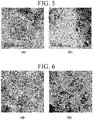
- FIG. 5 are TEM images showing the electrode produce using the electrode slurry of Example 1 before and after the voltage cycling test
- (a) and (b) of FIG. 6 are TEM images showing the electrode produced using the electrode slurry of Comparative Example 1 before and after the voltage cycling test.
Landscapes
- Chemical & Material Sciences (AREA)
- Chemical Kinetics & Catalysis (AREA)
- General Chemical & Material Sciences (AREA)
- Electrochemistry (AREA)
- Engineering & Computer Science (AREA)
- Manufacturing & Machinery (AREA)
- Sustainable Development (AREA)
- Sustainable Energy (AREA)
- Life Sciences & Earth Sciences (AREA)
- Materials Engineering (AREA)
- Inert Electrodes (AREA)
- Fuel Cell (AREA)
- Catalysts (AREA)
Abstract
Description
- The present disclosure relates to an electrode for fuel cells, a method of producing the same, and a membrane-electrode assembly including the same. More particularly, the present disclosure relates to an electrode for fuel cells having high durability by preventing catalyst deterioration due to agglomeration, precipitation, dissolution, and/or migration of metal catalyst particles, a method of producing the same, and a membrane-electrode assembly including the same.
- A polymer electrolyte membrane fuel cell (PEMFC), which generates electricity using a stacked structure of unit cells, each including a membrane-electrode assembly (MEA) and a separator (also referred to as a "bipolar plate"), is drawing attention as a next-generation energy source capable of replacing fossil fuels due to the high energy efficiency and environmental friendliness thereof.
- The membrane-electrode assembly generally includes an anode (also referred to as a "fuel electrode"), a cathode (also referred to as an "air electrode"), and a polymer electrolyte membrane (PEM) interposed therebetween.
- When fuel such as hydrogen gas is supplied to an anode, the hydrogen at the anode is oxidized to produce a proton (H+) and an electron (e-). The produced proton is transferred to the cathode through the polymer electrolyte membrane (PEM), whereas the generated electron is transferred to the cathode through an external circuit. Oxygen in the air supplied to the cathode is bonded to the proton and the electron, and thus is reduced to thereby produce water.
- Platinum or platinum alloys, having high catalytic activity and high corrosion resistance, are used as a metal catalyst for forming an electrode for a fuel cell.
- In addition, in an effort to increase the active surface area of the catalyst, a catalyst formed by dispersing metal catalyst particles on the surface of an electrically conductive support (e.g., carbon, metal oxide or C3N4) has been generally used.
-
FIG. 1 is a schematic diagram showing a conventional electrode for fuel cells before and after a voltage cycling test (VC test). - A conventional electrode for fuel cells includes a
catalyst 10 and anionomer layer 20 disposed on thecatalyst 10. Thecatalyst 10 includes asupport 11 and a plurality ofmetal catalyst particles 12 supported on thesupport 111. - As illustrated in
FIG. 1 , when the fuel cell is operated for a long period of time, agglomeration (11a), precipitation, dissolution, and/or migration (11b) of the metal catalyst is caused by high-voltage and highly acidic environments, which accelerates the degradation of thecatalyst 10. Therefore, it is very important to prevent deterioration of the catalyst upon long-term operation of the fuel cell to increase the durability and lifespan of the fuel cell. - In an attempt to prevent deterioration of the catalyst, coating the surface of the metal catalyst particles with a carbon shell has been suggested. However, the carbon shell is disadvantageous because it reduces the active area of the catalyst and interferes with the transfer of substances such as gas and/or water and thus decreases the output performance of the fuel cell. In addition, the carbon shell is not economical because it requires a separate process for introducing the carbon shell.
- Therefore, the present disclosure relates to an electrode for fuel cells that is capable of preventing problems caused by limitations and disadvantages of the related technology as described above, a method of producing the same, and a membrane-electrode assembly including the same.
- It is one object of the present disclosure to provide an electrode for fuel cells having high durability by preventing catalyst deterioration due to agglomeration, precipitation, dissolution, and/or migration of metal catalyst particles.
- It is another object of the present disclosure to provide a method of producing an electrode for fuel cells having high durability by preventing catalyst deterioration due to agglomeration, precipitation, dissolution, and/or migration of metal catalyst particles.
- It is another object of the present disclosure to provide a membrane-electrode assembly having high durability.
- In addition to the aspects of the present disclosure described above, other features and advantages of the present disclosure will be described in the following detailed description, or will be more clearly understood by those skilled in the art to which the present disclosure pertains.
- In accordance with one aspect of the present disclosure, provided is an electrode for a fuel cell including: a catalyst including a support and a plurality of metal catalyst particles supported on the support; and an ionomer layer coated on at least a part of the catalyst, wherein the ionomer layer includes an ionomer and a chelating agent.
- The ionomer layer may be bonded to the catalyst using only a physical bond, not a chemical bond.
- The ionomer may be a fluorine-based ionomer or a hydrocarbon-based ionomer.
- The chelating agent may be dimercaprol, phthalocyanine, M-phthalocyanine (wherein M is Cu, Co, Fe, or Mo), penicillamine, succimer, deferoxamine, EDTA, EGTA, Prussian blue, vitamin B-12, α-lipoic acid, ethylenediamine, triethylamine, phenanthroline, desferrioxamine, deferiprone, or a mixture of two or more thereof.
- The chelating agent may be dimercaprol, penicillamine, succimer, α-lipoic acid, triethylamine, deferiprone, or a mixture of two or more thereof.
- The chelating agent may include at least one S atom.
- The chelating agent including at least one S atom may be dimercaprol, penicillamine, succimer, α-lipoic acid, or a mixture of two or more thereof.
- The chelating agent may include at least two S atoms.
- The chelating agent including at least two S atoms may be dimercaprol, succimer, α-lipoic acid, or a mixture of two or more thereof.
- In another aspect of the present disclosure, provided is a method of producing an electrode for a fuel cell including: preparing an electrode slurry containing a catalyst, an ionomer, a chelating agent, and a dispersion medium; coating a film or a membrane with the electrode slurry to form a slurry layer; and removing the dispersion medium from the slurry layer.
- The electrode slurry may contain 0.01 to 10 parts by weight of the chelating agent based on 100 parts by weight of the ionomer.
- The preparing the electrode slurry may include: preparing a mixture containing the ionomer and the chelating agent; preparing a catalyst dispersion containing the catalyst and the dispersion medium; mixing the mixture with the catalyst dispersion to obtain a mixed solution; and dispersing the mixed solution using a homogenizer, a high-pressure disperser, a ball mill, a powder mixer, or a resonant acoustic mixer.
- The preparing the catalyst dispersion may include: wetting the catalyst with water; and dispersing the catalyst wetted with water in the dispersion medium.
- The preparing the electrode slurry may include: preparing a mixture containing the ionomer and the chelating agent; preparing a catalyst dispersion containing the catalyst; mixing the mixture with the catalyst dispersion to obtain a mixed solution; dispersing the mixed solution using a homogenizer, a high-pressure disperser, a ball mill, a powder mixer, or a resonance acoustic mixer; drying the dispersed mixed solution to obtain a solid; heat-treating the solid; and dispersing the heat-treated solid in the dispersion medium using a homogenizer, a high-pressure disperser, a ball mill, a powder mixer, or a resonance acoustic mixer.
- The catalyst dispersion may be prepared by dispersing the catalyst in water.
- The preparing the electrode slurry may include: mixing an ionomer dispersion containing the ionomer with a catalyst dispersion containing the catalyst to obtain a first mixed solution; dispersing the first mixed solution using a homogenizer, a high-pressure disperser, a ball mill, a powder mixer, or a resonance acoustic mixer; drying the dispersed first mixed solution to obtain a solid; heat-treating the solid; mixing the heat-treated solid with the dispersion medium to obtain a second mixed solution; preparing a mixture containing the ionomer and the chelating agent; mixing the mixture with the second mixed solution to obtain a third mixed solution; and dispersing the third mixed solution using a homogenizer, a high-pressure disperser, a ball mill, a powder mixer, or a resonance acoustic mixer.
- The catalyst dispersion may contain water as a dispersion medium.
- The preparing the electrode slurry may include: preparing a mixture containing the ionomer and the chelating agent; preparing a catalyst dispersion containing the catalyst; mixing a part of the mixture with the catalyst dispersion to obtain a first mixed solution; dispersing the first mixed solution using a homogenizer, a high-pressure disperser, a ball mill, a powder mixer, or a resonance acoustic mixer; drying the dispersed first mixed solution to obtain a solid; heat-treating the solid; mixing the heat-treated solid and the remainder of the mixture with the dispersion medium to obtain a second mixed solution; and dispersing the second mixed solution using a homogenizer, a high-pressure disperser, a ball mill, a powder mixer, or a resonance acoustic mixer.
- The catalyst dispersion may be prepared by dispersing the catalyst in water.
- In another aspect of the present disclosure, provided is a membrane-electrode assembly including an anode, a cathode, and a polymer electrolyte membrane interposed between the anode and the cathode, wherein at least one of the anode and cathode is the electrode described above.
- The general description of the present disclosure as provided above is only for illustration or description of the present disclosure, and does not limit the scope of the present disclosure.
- According to the present disclosure, an electrode for a fuel cell is formed using an electrode slurry containing a chelating agent, so that the ionomer layer containing the chelating agent in addition to the ionomer covers at least a part of the catalyst. The ionomer layer of the present disclosure captures the metal ions obtained from the metal catalyst particles and allows the metal ions to return to the original place thereof when the environment changes, thereby inhibiting the agglomeration and precipitation of the metal catalyst particles and preventing the dissolution and migration of the metal catalyst.
- Therefore, according to the present disclosure, the durability of an electrode for a fuel cell and a membrane-electrode assembly including the same can be improved, and thus the lifespan of the fuel cell can be prolonged by preventing catalyst deterioration due to agglomeration, deposition, elution, and/or movement of metal catalyst particles.
- The accompanying drawings, which are provided for better understanding of the present disclosure and constitute a part of the present specification, are given to exemplify the embodiments of the present disclosure and describe the principles and features of the present disclosure with reference to the following detailed description, in which:
-
FIG. 1 is a schematic diagram showing a conventional electrode for fuel cells before and after a voltage cycling test (VC test); -
FIG. 2 is a schematic diagram showing an electrode for fuel cells according to an embodiment of the present disclosure; -
FIG. 3 is a schematic diagram showing an electrode for fuel cells according to an embodiment of the present disclosure after a voltage cycling test; -
FIG. 4 is a transmission electron microscope (TEM) image showing an electrode produced using the electrode slurry of Example 1; - (a) and (b) of
FIG. 5 are TEM images showing the electrode produced using the electrode slurry of Example 1 before and after a voltage cycling test; and - (a) and (b) of
FIG. 6 are TEM images showing the electrode produced using the electrode slurry of Comparative Example 1 before and after a voltage cycling test. - Hereinafter, the present disclosure will be described in more detail with reference to specific examples. However, the following examples are provided only for better understanding of the present disclosure, and should not be construed as limiting the scope of the present disclosure.
-
FIG. 2 is a schematic diagram showing anelectrode 100 for a fuel cell according to an embodiment of the present disclosure. - As illustrated in
FIG. 2 , theelectrode 100 for a fuel cell of the present disclosure includes acatalyst 110 and anionomer layer 120 coated on at least a part of thecatalyst 110. - The
catalyst 110 includes asupport 111 and a plurality ofmetal catalyst particles 112 supported on thesupport 111. - The
support 111 may be (i) a carbon-based support, (ii) a porous inorganic oxide support such as zirconia, alumina, titania, silica, and ceria, or (iii) a zeolite support. - The carbon-based support may be graphite, super P, carbon fiber, carbon sheet, carbon black, Ketjen black, Denka black, acetylene black, carbon nanotubes (CNT), carbon spheres, carbon ribbon, fullerene, active carbon, carbon nanowires, carbon nanoballs, carbon nanohorns, carbon nanocages, carbon nanorings, ordered nano-/mesoporous carbon, carbon aerogel, mesoporous carbon, graphene, stabilized carbon, or a combination of two or more thereof.
- The
metal catalyst particles 112 may be platinum (Pt) particles or platinum-based alloy particles. - The platinum-based alloy may be Pt-Pd, Pt-Mn, Pt-Sn, Pt-Mo, Pt-W, Pt-Ru, Pt-Ru-W, Pt-Ru-Ni, Pt-Ru-Mo, Pt-Ru-Rh-Ni, Pt-Ru-Sn-W, Pt-Ru-Ir-Ni, Pt-Co, Pt-Co-Mn, Pt-Co-Ni, Pt-Co-Fe, Pt-Co-Ir, Pt-Co-S, Pt-Co-P, Pt-Fe, Pt-Fe-Ir, Pt-Fe-S, Pt-Fe-P, Pt-Au-Co, Pt-Au-Fe, Pt-Au-Ni, Pt-Ni, Pt-Ni-Ir, Pt-Cr, or Pt-Cr-Ir.
- The
ionomer layer 120 of the present disclosure includes an ionomer and a chelating agent. - According to an embodiment of the present disclosure, the
ionomer layer 120 is bonded to thecatalyst 110 only through a physical bond rather than a chemical bond, thereby preventing deterioration of the catalytic activity of thecatalyst 110. - The ionomer of the
ionomer layer 120 serves to transfer cations, and also serves as a binder for improving adhesion between thecatalyst 110 and the polymer electrolyte membrane (PEM). - The ionomer may have at least one ion-conducting group selected from the group consisting of a sulfonic acid group, a carboxyl group, a boronic acid group, a phosphoric acid group, an imide group, a sulfonimide group, a sulfonamide group, and a sulfonic fluoride group.
- For example, the ionomer may be a fluorine-based ionomer such as poly(perfluorosulfonic acid) or poly(perfluorocarboxylic acid).
- Alternatively, the ionomer may be a hydrocarbon-based polymer such as sulfonated polyimide (S-PI), sulfonated polyarylethersulfone (S-PAES), sulfonated polyetheretherketone (SPEEK), sulfonated polybenzimidazole (SPBI), sulfonated polysulfone (S-PSU), sulfonated polystyrene (S-PS), sulfonated polyphosphazene, sulfonated polyquinoxaline, sulfonated polyketone, sulfonated polyphenylene oxide, sulfonated polyether sulfone, sulfonated polyether ketone, sulfonated polyphenylene sulfone, sulfonated polyphenylene sulfide, sulfonated polyphenylene sulfide sulfone, sulfonated polyphenylene sulfide sulfone nitrile, sulfonated polyarylene ether, sulfonated polyarylene ether nitrile, sulfonated polyarylene ether ether nitrile, or sulfonated polyarylene ether sulfone ketone.
- The chelating agent of the
ionomer layer 120 captures the metal ions derived from themetal catalyst particles 112 during long-term operation of the fuel cell, and allows the metal ions to return to the original place thereof when the environment changes, thereby inhibiting the agglomeration and precipitation of themetal catalyst particles 112 and preventing the dissolution and migration of the metal catalyst. -
FIG. 3 is a schematic diagram showing an electrode for a fuel cell according to an embodiment of the present disclosure after a voltage cycling test and shows that metal ions (Pt2+) derived from themetal catalyst particles 111b form a coordination bond with a chelating agent (dimercaprol), thereby minimizing theagglomeration 111a of the metal catalyst particles and returning the metal ions (Pt2+) to the originalmetal catalyst particles 111b upon environmental changes, thus preventing deterioration of thecatalyst 110 due to dissolution and/or movement of the metal catalyst. - The chelating agent of the present disclosure is dimercaprol, phthalocyanine, M-phthalocyanine (where M is Cu, Co, Fe, or Mo), penicillamine, Succimer, deferoxamine, EDTA, EGTA, Prussian blue, vitamin B-12, α-lipoic acid, ethylenediamine, triethylamine, phenanthroline, desferrioxamine, deferiprone, or a mixture of two or more thereof, more preferably dimercaprol, penicillamine, succimer, α-lipoic acid, triethylamine, deferiprone, or a mixture of two or more thereof.
- Preferably, the chelating agent of the present disclosure includes at least one S atom, and may be, for example, dimercaprol, penicillamine, succimer, α-lipoic acid, or a mixture of two or more thereof.
- More preferably, the chelating agent of the present disclosure contains at least two S atoms, and may be, for example, dimercaprol, succimer, α-lipoic acid, or a mixture of two or more thereof.
- Compared to other atoms (e.g., N atom), the S atom binds well with metal ions derived from the
metal catalyst particles 111b and has stronger binding force therewith, thereby effectively capturing the metal ions and increasing the durability of theelectrode 100. In particular, dimercaprol forms a chelate bond well enough to be biochemically used as an antidote for heavy metals. - Hereinafter, a method of producing the
electrode 100 for a fuel cell of the present disclosure will be described in detail. - The method of the present disclosure includes: (i) preparing an electrode slurry containing a catalyst, an ionomer, a chelating agent and a dispersion medium; (ii) coating a film or a membrane with the electrode slurry to form a slurry layer; and (iii) removing the dispersion medium from the slurry layer.
- Each of the catalyst, the ionomer, and the chelating agent has been described in detail above, and thus a description thereof will be omitted below.
- The dispersion medium may be water, a hydrophilic solvent, an organic solvent, or a mixture of two or more thereof.
- The hydrophilic solvent may be a compound containing, as a main chain, a linear or branched saturated or unsaturated hydrocarbon having 1 to 12 carbon atoms, and having at least one functional group selected from the group consisting of alcohols, isopropyl alcohol, ketones, aldehydes, carbonates, carboxylates, carboxylic acids, ethers, and amides.
- The organic solvent may be N-methylpyrrolidone (NMP), dimethylsulfoxide (DMSO), tetrahydrofuran (THF), dimethylacetamide (DMAc), or a mixture of two or more thereof, but is not limited thereto.
- According to an embodiment of the present disclosure, the dispersion medium of the electrode slurry may be ethanol, distilled water, isopropyl alcohol, normal propyl alcohol, butanol, or a mixture of two or more thereof, but is not limited thereto.
- The electrode slurry may contain 0.01 to 10 parts by weight of the chelating agent based on 100 parts by weight of the ionomer. When the content of the chelating agent is less than 0.01 parts by weight, a satisfactory effect of preventing catalyst deterioration cannot be obtained. On the other hand, when the content of the chelating agent exceeds 10 parts by weight, the activity of the metal catalyst may be inhibited, resulting in deterioration of the performance of the fuel cell.
- An electrode is formed on at least one surface of the polymer electrolyte membrane (PEM) through decal transfer or direct coating using the electrode slurry.
- That is, in the case of the decal transfer method, a release film is coated with the electrode slurry to form a slurry layer, the dispersion medium is removed from the slurry layer through a drying process to form an electrode, hot-pressing is performed in the state in which the release film and the polymer electrolyte membrane (PEM) are stacked such that the release film contacts the polymer electrolyte membrane (PEM), and then the release film is removed.
- In the case of the direct coating method, a mask film having an electrode window is stacked on one surface of the polymer electrolyte membrane (PEM), the electrode slurry is coated on one surface of the polymer electrolyte membrane (PEM) to form a slurry layer, the dispersion medium is removed from the slurry layer to form an electrode, and then the mask film is removed.
- The electrode slurry of the present disclosure may be prepared through any of various methods.
- A first method of preparing the electrode slurry may include (i) preparing a mixture containing the ionomer and the chelating agent, (ii) preparing a catalyst dispersion containing the catalyst and the dispersion medium, (iii) mixing the mixture with the catalyst dispersion to obtain a mixed solution, and (iv) dispersing the mixed solution using a homogenizer, a high-pressure disperser, a ball mill, a powder mixer, or a resonant acoustic mixer.
- The mixture containing the ionomer and the chelating agent may be obtained by adding the chelating agent to the ionomer dispersion, followed by mixing to homogeneity. The ionomer dispersion may be a commercially available fluorine-based ionomer dispersion (e.g., Nafion dispersion).
- The catalyst dispersion may be obtained by wetting the catalyst with water and dispersing the catalyst in the dispersion medium for the electrode slurry according to the present disclosure described above. The reason for wetting the catalyst with water is that the catalyst may ignite if brought into contact with alcohol or the like first, due to the high reactivity of the catalyst.
- A second method of preparing the electrode slurry may include (i) preparing a mixture containing the ionomer and the chelating agent, (ii) preparing a catalyst dispersion containing the catalyst, (iii) mixing the mixture with the catalyst dispersion to obtain a mixed solution, (iv) dispersing the dispersed mixed solution using a homogenizer, a high-pressure disperser, a ball mill, a powder mixer, or a resonance acoustic mixer, (v) drying the dispersed mixed solution to obtain a solid, (vi) heat-treating the solid, and (vii) dispersing the heat-treated solid in the dispersion medium using a homogenizer, a high-pressure disperser, a ball mill, a powder mixer, or a resonance acoustic mixer.
- The mixture containing the ionomer and the chelating agent may be obtained by adding the chelating agent to the ionomer dispersion, followed by mixing to homogeneity. The ionomer dispersion may be a commercially available fluorine-based ionomer dispersion (e.g., Nafion dispersion).
- The catalyst dispersion may be prepared by dispersing the catalyst in water. The reason for using water as the dispersion medium is that the catalyst may ignite if brought into contact with alcohol or the like first due to the high reactivity of the catalyst.
- The drying may be performed at 60 to 90°C for 5 to 10 hours, and the heat treatment may be performed at 90 to 150°C for 1 to 3 hours.
- A third method of preparing the electrode slurry may include (i) mixing an ionomer dispersion containing the ionomer with a catalyst dispersion containing the catalyst to obtain a first mixed solution, (ii) dispersing the first mixed solution using a homogenizer, a high-pressure disperser, a ball mill, a powder mixer, or a resonance acoustic mixer, (iii) drying the dispersed first mixed solution to obtain a solid, (iv) heat-treating the solid, (v) mixing the heat-treated solid with the dispersion medium to obtain a second mixed solution, (vi) preparing a mixture containing the ionomer and the chelating agent, (vii) mixing the mixture with the second mixed solution to obtain a third mixed solution, and (viii) dispersing the third mixed solution using a homogenizer, a high-pressure disperser, a ball mill, a powder mixer, or a resonance acoustic mixer.
- The ionomer dispersion may be a commercially available fluorine-based ionomer dispersion (e.g., Nafion dispersion).
- The catalyst dispersion may contain water as a dispersion medium.
- The drying may be performed at 60 to 90°C for 5 to 10 hours, and the heat treatment may be performed at 90 to 150°C for 1 to 3 hours.
- A fourth method of preparing the electrode slurry may include (i) preparing a mixture containing the ionomer and the chelating agent, (ii) preparing a catalyst dispersion containing the catalyst, (iii) mixing a part of the mixture with the catalyst dispersion to obtain a first mixed solution, (iv) dispersing the first mixed solution using a homogenizer, a high-pressure disperser, a ball mill, a powder mixer, or a resonance acoustic mixer, (v) drying the dispersed first mixed solution to obtain a solid, (vi) heat-treating the solid, (vii) mixing the heat-treated solid and the remainder of the mixture with the dispersion medium to obtain a second mixed solution, and (viii) dispersing the second mixed solution using a homogenizer, a high-pressure disperser, a ball mill, a powder mixer, or a resonance acoustic mixer.
- The mixture containing the ionomer and the chelating agent may be obtained by adding the chelating agent to the ionomer dispersion, followed by mixing to homogeneity. The ionomer dispersion may be a commercially available fluorine-based ionomer dispersion (e.g., Nafion dispersion).
- The catalyst dispersion may be prepared by dispersing the catalyst in water.
- The drying may be performed at 60 to 90°C for 5 to 10 hours, and the heat treatment may be performed at 90 to 150°C for 1 to 3 hours.
- The membrane-electrode assembly (MEA) of the present disclosure can be manufactured by forming an anode and a cathode on two surfaces of the polymer electrolyte membrane (PEM) according to the decal transfer method or the direct coating method described above using the electrode slurry prepared according to any one of the four methods described above.
- Alternatively, the membrane-electrode assembly (MEA) of the present disclosure includes an anode, a cathode, and a polymer electrolyte membrane (PEM) interposed therebetween, wherein only one of the anode and the cathode is an electrode of the present disclosure, and the other is a conventional electrode.
- Hereinafter, the present disclosure will be described in more detail with reference to specific examples. These examples are provided only for better understanding, and should not be construed as limiting the scope of the present disclosure.
- 0.04 g of dimercaprol was added to 5 g of a poly(perfluorosulfonic acid) dispersion (solid content: 10 wt%), followed by mixing to homogeneity to obtain a mixture. 1 g of a Pt/C catalyst was wetted with water and then dispersed in 10 g of a dispersion medium (isopropyl alcohol) to obtain a catalyst dispersion. The mixture was mixed with the catalyst dispersion to obtain a mixed solution, and the mixed solution was dispersed using a high-pressure disperser to complete an electrode slurry.
- 0.04 g of dimercaprol was added to 5 g of a poly(perfluorosulfonic acid) dispersion (solid content: 10 wt%), followed by mixing to homogeneity to obtain a mixture. 1 g of a Pt/C catalyst was dispersed in 100 g of water to obtain a catalyst dispersion. The mixture was mixed with the catalyst dispersion to obtain a mixed solution, and the mixed solution was dispersed using a high-pressure disperser. The dispersed mixed solution was dried at 80°C for 8 hours to obtain a solid, and the solid was heat-treated at 120°C for 2 hours. The heat-treated solid was dispersed in 10 g of a dispersion medium (isopropyl alcohol) using a high-pressure disperser to complete an electrode slurry.
- The catalyst dispersion obtained by dispersing 1 g of Pt/C catalyst in 100 g of water was mixed to homogeneity with 4 g of a poly(perfluorosulfonic acid) dispersion (solid content: 10 wt%) to obtain a first mixed solution. The first mixed solution was dispersed using a high-pressure disperser. The dispersed first mixed solution was dried at 80°C for 8 hours to obtain a solid, and the solid was heat- treated at 120°C for 2 hours. The heat-treated solid was mixed with 10 g of a dispersion medium (isopropyl alcohol) to obtain a second mixed solution. The second mixed solution was mixed with a mixture of 0.04 g of dimercaprol and 1 g of a poly(perfluorosulfonic acid) dispersion (solid content: 10 wt.%) to obtain a third mixed solution. Subsequently, the third mixed solution was dispersed using a high-pressure disperser to complete an electrode slurry.
- 0.04 g of dimercaprol was added to 5 g of a poly(perfluorosulfonic acid) dispersion (solid content: 10 wt%), followed by mixing to homogeneity to obtain 5.04 g of a mixture. 1 g of a Pt/C catalyst was dispersed in 100 g of water to obtain a catalyst dispersion. 4 g of the mixture was mixed with the catalyst dispersion to obtain a first mixed solution. Then, the first mixed solution was dispersed using a high-pressure disperser. The dispersed first mixed solution was dried at 80°C for 8 hours to obtain a solid, and the solid was heat-treated at 120°C for 2 hours. The heat-treated solid, 1.04 g of the mixture, and 10 g of a dispersion medium (isopropyl alcohol) were mixed to obtain a second mixed solution. Subsequently, the second mixed solution was dispersed using a high-pressure disperser to complete an electrode slurry.
- 1 g of a Pt/C catalyst was wetted in water and then dispersed in 10 g of a dispersion medium (isopropyl alcohol) to obtain a catalyst dispersion. Subsequently, the catalyst dispersion was mixed with 5 g of a poly(perfluorosulfonic acid) dispersion (solid content: 10 wt.%) and the resulting mixture was dispersed using a high-pressure disperser to complete an electrode slurry.
- A catalyst dispersion, obtained by dispersing 1 g of Pt/C catalyst in 100 g of water, was mixed with 5 g of a poly(perfluorosulfonic acid) dispersion (solid content: 10 wt.%) to obtain a mixed solution. Then, the mixed solution was dispersed using a high-pressure disperser. The dispersed mixed solution was dried at 80°C for 8 hours to obtain a solid, and the solid was heat-treated at 120°C for 2 hours. The heat-treated solid was mixed with 10 g of a dispersion medium (isopropyl alcohol) and then the resulting mixture was dispersed using a high-pressure disperser to complete an electrode slurry.
- The electrode slurry was cast on a rotating disk electrode (RDE) and dried to produce an electrode. A cyclic voltammetry (CV) test (temperature: room temperature, electrolyte solution: 0.1M HClO4 aqueous solution saturated with N2) was performed on the electrode using an electrochemical measuring device to measure the electrochemical surface area (ECSA) of the catalyst. Subsequently, the electrolyte solution was saturated with O2, and then a voltage cycling test (30,000 cycles) was performed at 0.6 to 1.0V. The electrochemical surface area (ECSA) of the electrode was measured using the method described above before and after the voltage-cycling test.
- ECSA loss was calculated based on the measured ECSA values before and after the voltage-cycling test, and the results are shown in Table 1 below.
[Table 1] Example 1 Example 2 Example 3 Example 4 Comparative Example 1 Comparative Example 2 ECSA loss 35% 30% 33% 31% 46% 43% - As can be seen from Table 1 above, the electrodes produced from electrode slurries of Examples exhibited a notably lower ECSA loss than the electrodes produced from electrode slurries of Comparative Examples.
- Meanwhile,
FIG. 4 is a transmission electron microscope (TEM) image of an electrode produced using the electrode slurry of Example 1. As can be seen fromFIG. 4 , the ionomer layer including the chelating agent in the electrode produced from the electrode slurry of Example 1 is well distributed around the catalyst. - (a) and (b) of
FIG. 5 are TEM images showing the electrode produce using the electrode slurry of Example 1 before and after the voltage cycling test, and (a) and (b) ofFIG. 6 are TEM images showing the electrode produced using the electrode slurry of Comparative Example 1 before and after the voltage cycling test. - When comparing
FIG. 5 withFIG. 6 , agglomeration of the metal catalyst particles and dissolution of the metal catalyst upon the voltage cycling test were remarkably suppressed in the electrode produced using the electrode slurry of Example 1, compared to the electrode produced using the electrode slurry of Comparative Example 1. In other words, it can be seen that the chelating agent included in the electrode of the present disclosure can prevent deterioration of the catalyst, thereby improving the durability of the electrode.
Claims (20)
- An electrode for a fuel cell comprising:a catalyst comprising a support and a plurality of metal catalyst particles supported on the support; andan ionomer layer coated on at least a part of the catalyst,wherein the ionomer layer comprises an ionomer and a chelating agent.
- The electrode according to claim 1, wherein the ionomer layer is bonded to the catalyst only through a physical bond rather than a chemical bond.
- The electrode according to claim 1, wherein the ionomer is a fluorine-based ionomer or a hydrocarbon-based ionomer.
- The electrode according to claim 1, wherein the chelating agent is dimercaprol, phthalocyanine, M-phthalocyanine (wherein M is Cu, Co, Fe, or Mo), penicillamine, succimer, deferoxamine, EDTA, EGTA, Prussian blue, vitamin B-12, α-lipoic acid, ethylenediamine, triethylamine, phenanthroline, desferrioxamine, deferiprone, or a mixture of two or more thereof.
- The electrode according to claim 4, wherein the chelating agent is dimercaprol, penicillamine, succimer, α-lipoic acid, triethylamine, deferiprone, or a mixture of two or more thereof.
- The electrode according to claim 1, wherein the chelating agent comprises at least one S atom.
- The electrode according to claim 6, wherein the chelating agent comprising at least one S atom is dimercaprol, penicillamine, succimer, α-lipoic acid, or a mixture of two or more thereof.
- The electrode according to claim 1, wherein the chelating agent comprises at least two S atoms.
- The electrode according to claim 8, wherein the chelating agent comprising at least two S atoms is dimercaprol, succimer, α-lipoic acid, or a mixture of two or more thereof.
- A method of producing an electrode for a fuel cell comprising:preparing an electrode slurry containing a catalyst, an ionomer, a chelating agent, and a dispersion medium;coating a film or a membrane with the electrode slurry to form a slurry layer; andremoving the dispersion medium from the slurry layer.
- The method according to claim 10, wherein the electrode slurry comprises 0.01 to 10 parts by weight of the chelating agent based on 100 parts by weight of the ionomer.
- The method according to claim 10, wherein the preparing the electrode slurry comprises:preparing a mixture containing the ionomer and the chelating agent;preparing a catalyst dispersion containing the catalyst and the dispersion medium;mixing the mixture with the catalyst dispersion to obtain a mixed solution; anddispersing the mixed solution using a homogenizer, a high-pressure disperser, a ball mill, a powder mixer, or a resonant acoustic mixer.
- The method according to claim 12, wherein the preparing the catalyst dispersion comprises:wetting the catalyst with water; anddispersing the catalyst wetted with water in the dispersion medium.
- The method according to claim 10, wherein the preparing the electrode slurry comprises:preparing a mixture containing the ionomer and the chelating agent;preparing a catalyst dispersion containing the catalyst;mixing the mixture with the catalyst dispersion to obtain a mixed solution;dispersing the mixed solution using a homogenizer, a high-pressure disperser, a ball mill, a powder mixer, or a resonance acoustic mixer;drying the dispersed mixed solution to obtain a solid;heat-treating the solid; anddispersing the heat-treated solid in the dispersion medium using a homogenizer, a high-pressure disperser, a ball mill, a powder mixer, or a resonance acoustic mixer.
- The method according to claim 14, wherein the catalyst dispersion is prepared by dispersing the catalyst in water.
- The method according to claim 10, wherein the preparing the electrode slurry comprises:mixing an ionomer dispersion containing the ionomer with a catalyst dispersion containing the catalyst to obtain a first mixed solution;dispersing the first mixed solution using a homogenizer, a high-pressure disperser, a ball mill, a powder mixer, or a resonance acoustic mixer;drying the dispersed first mixed solution to obtain a solid;heat-treating the solid;mixing the heat-treated solid with the dispersion medium to obtain a second mixed solution;preparing a mixture containing the ionomer and the chelating agent;mixing the mixture with the second mixed solution to obtain a third mixed solution; anddispersing the third mixed solution using a homogenizer, a high-pressure disperser, a ball mill, a powder mixer, or a resonance acoustic mixer.
- The method according to claim 16, wherein the catalyst dispersion comprises water as a dispersion medium.
- The method according to claim 10, wherein the preparing the electrode slurry comprises:preparing a mixture containing the ionomer and the chelating agent;preparing a catalyst dispersion containing the catalyst;mixing a part of the mixture with the catalyst dispersion to obtain a first mixed solution;dispersing the first mixed solution using a homogenizer, a high-pressure disperser, a ball mill, a powder mixer, or a resonance acoustic mixer;drying the dispersed first mixed solution to obtain a solid;heat-treating the solid;mixing the heat-treated solid and a remainder of the mixture with the dispersion medium to obtain a second mixed solution; anddispersing the second mixed solution using a homogenizer, a high-pressure disperser, a ball mill, a powder mixer, or a resonance acoustic mixer.
- The method according to claim 18, wherein the catalyst dispersion is prepared by dispersing the catalyst in water.
- A membrane-electrode assembly comprising:an anode;a cathode; anda polymer electrolyte membrane interposed between the anode and the cathode,wherein at least one of the anode and cathode is the electrode according to claim 1.
Applications Claiming Priority (2)
| Application Number | Priority Date | Filing Date | Title |
|---|---|---|---|
| KR1020190178200A KR102756173B1 (en) | 2019-12-30 | 2019-12-30 | Fuel Cell Electrode Having High Durability, Method for Manufacturing The Same, and Membrane-Electrode Assembly Comprising The Same |
| PCT/KR2020/018963 WO2021137513A1 (en) | 2019-12-30 | 2020-12-23 | Electrode for fuel cell having high durability, method for manufacturing same, and membrane-electrode assembly comprising same |
Publications (2)
| Publication Number | Publication Date |
|---|---|
| EP4086987A1 true EP4086987A1 (en) | 2022-11-09 |
| EP4086987A4 EP4086987A4 (en) | 2025-04-02 |
Family
ID=76687428
Family Applications (1)
| Application Number | Title | Priority Date | Filing Date |
|---|---|---|---|
| EP20910671.5A Pending EP4086987A4 (en) | 2019-12-30 | 2020-12-23 | ELECTRODE FOR A FUEL CELL HAVING HIGH DURABILITY, METHOD FOR MANUFACTURING SAME, AND MEMBRANE-ELECTRODE ASSEMBLY COMPRISING SAME |
Country Status (7)
| Country | Link |
|---|---|
| US (1) | US12021283B2 (en) |
| EP (1) | EP4086987A4 (en) |
| JP (1) | JP7498271B2 (en) |
| KR (1) | KR102756173B1 (en) |
| CN (1) | CN114391191A (en) |
| TW (1) | TWI762116B (en) |
| WO (1) | WO2021137513A1 (en) |
Families Citing this family (9)
| Publication number | Priority date | Publication date | Assignee | Title |
|---|---|---|---|---|
| CN114146622A (en) * | 2021-07-13 | 2022-03-08 | 南方科技大学 | Membrane electrode slurry and preparation method thereof |
| CN115911413A (en) * | 2021-09-30 | 2023-04-04 | 未势能源科技有限公司 | Catalyst slurry and preparation method thereof |
| CN116259770A (en) * | 2022-12-12 | 2023-06-13 | 广东凯金新能源科技股份有限公司 | A kind of Pt/C catalyst slurry and preparation method thereof |
| CN118231660B (en) * | 2023-09-21 | 2025-09-09 | 比亚迪股份有限公司 | Positive electrode slurry, positive electrode plate and sodium ion battery |
| CN117702165A (en) * | 2023-11-23 | 2024-03-15 | 西子清洁能源装备制造股份有限公司 | Catalyst carrier and catalyst with chestnut type carbon cage structure, preparation method thereof and application of catalyst carrier and catalyst in water electrolysis anode |
| WO2025143401A1 (en) * | 2023-12-28 | 2025-07-03 | 코오롱인더스트리 주식회사 | Membrane-electrode assembly for water electrolysis cell, manufacturing method therefor, and water electrolysis cell comprising membrane-electrode assembly |
| KR102976428B1 (en) * | 2023-12-28 | 2026-06-11 | 코오롱인더스트리 주식회사 | Membrane-electrode assembly for water electrolysis cell, method for manufacturing the same, and water electrolysis cell comprising the same |
| CN119852428B (en) * | 2025-01-17 | 2025-09-30 | 上海济平新能源科技有限公司 | Preparation method of fuel cell catalyst |
| CN120943399B (en) * | 2025-10-15 | 2026-02-03 | 南京大学 | Electrode preparation method of bioelectrochemical device and application thereof |
Family Cites Families (23)
| Publication number | Priority date | Publication date | Assignee | Title |
|---|---|---|---|---|
| US6358639B2 (en) * | 1999-08-27 | 2002-03-19 | Plug Power Llc | Methods and kits for decontaminating fuel cells |
| US7537857B2 (en) | 2003-12-17 | 2009-05-26 | Bdf Ip Holdings Ltd. | Reduced degradation of ion-exchange membranes in electrochemical fuel cells |
| CN102169998A (en) | 2006-09-13 | 2011-08-31 | 日立麦克赛尔株式会社 | Membrane electrode assembly and polymer electrolyte fuel cell |
| CN101547858B (en) | 2006-10-18 | 2013-06-12 | 新加坡科技研究局 | A method for functionalizing carbon materials |
| KR101483124B1 (en) | 2007-05-21 | 2015-01-16 | 삼성에스디아이 주식회사 | Membrane electrode assembly having a porous electrode catalyst layer, method of manufacturing the same, and fuel cell employing the same |
| US20090311568A1 (en) * | 2008-06-17 | 2009-12-17 | Canon Kabushiki Kaisha | Catalyst layer, membrane electrode assembly, fuel cell, and method for manufacturing catalyst layer |
| KR101080783B1 (en) * | 2008-10-06 | 2011-11-07 | 현대자동차주식회사 | Process for maufacturing electrode and Membrane-Electrode Assembly for Polymer Electrolyte Membrane Fuel Cell |
| JP2010244700A (en) | 2009-04-01 | 2010-10-28 | Tokuyama Corp | Ion conductivity imparting agent for electrode catalyst layer |
| GB0908089D0 (en) * | 2009-05-11 | 2009-06-24 | Nexeon Ltd | A binder for lithium ion rechargaable battery cells |
| JP2011044243A (en) | 2009-08-19 | 2011-03-03 | Hitachi Ltd | Membrane electrode assembly and fuel cell |
| WO2011057769A1 (en) * | 2009-11-10 | 2011-05-19 | Daimler Ag | Composite proton conducting electrolyte with improved additives for fuel cells |
| WO2012095862A2 (en) * | 2011-01-11 | 2012-07-19 | Tata Chemicals Limited | An electrode for a fuel cell |
| JP2014050791A (en) | 2012-09-06 | 2014-03-20 | Osaka Univ | Solid composite material |
| JP2016504176A (en) | 2012-11-09 | 2016-02-12 | ビーエーエスエフ ソシエタス・ヨーロピアBasf Se | Method for producing a carbon-supported nickel-cobalt-oxide catalyst and its use in a rechargeable electrochemical metal-oxygen cell |
| KR101904896B1 (en) * | 2013-11-27 | 2018-10-05 | 삼성에스디아이 주식회사 | Positive active material for rechargeable lithium battery, method of preparing the same, and rechargeable lithium battery including the same |
| JP6731755B2 (en) * | 2015-06-12 | 2020-07-29 | 株式会社キャタラー | Dispersion of metal-containing particles, method for producing the same, and catalyst prepared using the dispersion |
| JP6818288B2 (en) | 2015-06-16 | 2021-01-20 | 国立大学法人東北大学 | Platinum group-supported catalyst and its manufacturing method |
| KR101922636B1 (en) * | 2017-02-23 | 2018-11-27 | 울산과학기술원 | Fuel cell membrane electrode assembly comprising hexagonal boron nitride thin film without interfacial binding layer |
| KR102272379B1 (en) | 2017-06-23 | 2021-07-02 | 코오롱인더스트리 주식회사 | Electrode with organic metal-oxide, method for manufacturing the same, membrane-electrode assembly comprising the same, and fuel cell comprising the membrane-electrode assembly |
| KR102323487B1 (en) | 2017-12-26 | 2021-11-10 | 코오롱인더스트리 주식회사 | Catalyst, method for manufacturing the same, electrode comprising the same, membrane-electrode assembly comprising the same, and fuel cell comprising the same |
| CN110350204B (en) * | 2019-07-10 | 2021-05-28 | 广东工业大学 | Fuel cell catalyst with gold nanocluster as core and platinum as shell and its preparation method and application |
| FR3099052B1 (en) * | 2019-07-23 | 2022-03-25 | Univ Franche Comte | Particulate structures based on gold nanoparticles, processes for their preparation and their uses in the treatment of solid tumors |
| KR102881926B1 (en) * | 2019-11-26 | 2025-11-05 | 현대자동차주식회사 | Catalyst slurry for fuel cell and manufacturing method thereof |
-
2019
- 2019-12-30 KR KR1020190178200A patent/KR102756173B1/en active Active
-
2020
- 2020-12-23 JP JP2022523721A patent/JP7498271B2/en active Active
- 2020-12-23 EP EP20910671.5A patent/EP4086987A4/en active Pending
- 2020-12-23 US US17/625,808 patent/US12021283B2/en active Active
- 2020-12-23 WO PCT/KR2020/018963 patent/WO2021137513A1/en not_active Ceased
- 2020-12-23 CN CN202080062620.1A patent/CN114391191A/en active Pending
- 2020-12-28 TW TW109146361A patent/TWI762116B/en active
Also Published As
| Publication number | Publication date |
|---|---|
| WO2021137513A1 (en) | 2021-07-08 |
| KR102756173B1 (en) | 2025-01-15 |
| JP7498271B2 (en) | 2024-06-11 |
| US20220263108A1 (en) | 2022-08-18 |
| TW202131544A (en) | 2021-08-16 |
| EP4086987A4 (en) | 2025-04-02 |
| JP2022553353A (en) | 2022-12-22 |
| US12021283B2 (en) | 2024-06-25 |
| KR20210085300A (en) | 2021-07-08 |
| TWI762116B (en) | 2022-04-21 |
| CN114391191A (en) | 2022-04-22 |
Similar Documents
| Publication | Publication Date | Title |
|---|---|---|
| US12021283B2 (en) | Electrode for fuel cell having high durability, method for manufacturing same, and membrane-electrode assembly comprising same | |
| KR101363797B1 (en) | Method for producing electrode material for fuel cell, electrode material for fuel cell, and fuel cell using the electrode material for fuel cell | |
| KR20050014828A (en) | Sulfonated conducting polymer-grafted carbon material for fuel cell application | |
| US20160315343A1 (en) | A process for the preparation of pbi based membrane electrode assembly (mea) with improved fuel cell performance and stability | |
| CN102257662B (en) | Anode catalyst layer for solid polymer fuel cell | |
| KR20240142360A (en) | Catalyst for Fuel Cell, Method for Manufacturing The Same, and Membrane-Electrode Assembly Comprising The Same | |
| JP2008171647A (en) | Catalyst for fuel cell, cathode for fuel cell, and polymer electrolyte fuel cell having the same | |
| JP2006260909A (en) | Membrane electrode assembly and polymer electrolyte fuel cell using the same | |
| KR20230103469A (en) | Electrolyte membrane for fuel cell and fuel cell comprising same | |
| JP5535773B2 (en) | Membrane-electrode structure for polymer electrolyte fuel cell | |
| JP7464553B2 (en) | Electrocatalyst | |
| JP2009252587A (en) | Manufacturing method of catalyst layer for fuel cell, and performance evaluation method of catalyst layer for fuel cell | |
| CN118266106A (en) | Carbon supported electrode | |
| JP2018085260A (en) | Electrocatalyst production method | |
| KR20230001894A (en) | Membrane-electrode assembly for fuel cell and fuel cell comprising same | |
| JP2004047386A (en) | Electrode catalyst for solid polymer electrolyte fuel cells | |
| WO2020217845A1 (en) | Membrane-electrode assembly and fuel battery using same | |
| JP2005190712A (en) | Catalyst-supporting electrode, MEA for fuel cell and fuel cell | |
| JP2010238415A (en) | Catalyst paste preparation method | |
| KR20230080751A (en) | Electrolyte membrane for fuel cell and fuel cell comprising same | |
| JP2023168683A (en) | Slurry manufacturing method | |
| CN121355279A (en) | A high-temperature proton exchange membrane fuel cell catalyst slurry, its preparation method, and its application. | |
| CN121366915A (en) | Membrane electrode assembly and fuel cell | |
| Tonnis | Integration of Highly Active Pt-Sn Nanoparticles into Practical Hydrogen and Direct Ethanol Fuel Cell Systems | |
| KR20230080747A (en) | Electrolyte membrane for fuel cell and fuel cell comprising same |
Legal Events
| Date | Code | Title | Description |
|---|---|---|---|
| STAA | Information on the status of an ep patent application or granted ep patent |
Free format text: STATUS: THE INTERNATIONAL PUBLICATION HAS BEEN MADE |
|
| PUAI | Public reference made under article 153(3) epc to a published international application that has entered the european phase |
Free format text: ORIGINAL CODE: 0009012 |
|
| STAA | Information on the status of an ep patent application or granted ep patent |
Free format text: STATUS: REQUEST FOR EXAMINATION WAS MADE |
|
| 17P | Request for examination filed |
Effective date: 20220316 |
|
| AK | Designated contracting states |
Kind code of ref document: A1 Designated state(s): AL AT BE BG CH CY CZ DE DK EE ES FI FR GB GR HR HU IE IS IT LI LT LU LV MC MK MT NL NO PL PT RO RS SE SI SK SM TR |
|
| DAV | Request for validation of the european patent (deleted) | ||
| DAX | Request for extension of the european patent (deleted) | ||
| A4 | Supplementary search report drawn up and despatched |
Effective date: 20250227 |
|
| RIC1 | Information provided on ipc code assigned before grant |
Ipc: H01M 4/92 20060101ALI20250221BHEP Ipc: H01M 8/1004 20160101ALI20250221BHEP Ipc: H01M 4/88 20060101ALI20250221BHEP Ipc: H01M 4/86 20060101AFI20250221BHEP |
|
| STAA | Information on the status of an ep patent application or granted ep patent |
Free format text: STATUS: EXAMINATION IS IN PROGRESS |
|
| 17Q | First examination report despatched |
Effective date: 20251017 |
|
| GRAP | Despatch of communication of intention to grant a patent |
Free format text: ORIGINAL CODE: EPIDOSNIGR1 |
|
| STAA | Information on the status of an ep patent application or granted ep patent |
Free format text: STATUS: GRANT OF PATENT IS INTENDED |
|
| GRAJ | Information related to disapproval of communication of intention to grant by the applicant or resumption of examination proceedings by the epo deleted |
Free format text: ORIGINAL CODE: EPIDOSDIGR1 |
|
| STAA | Information on the status of an ep patent application or granted ep patent |
Free format text: STATUS: EXAMINATION IS IN PROGRESS |
|
| GRAP | Despatch of communication of intention to grant a patent |
Free format text: ORIGINAL CODE: EPIDOSNIGR1 |
|
| STAA | Information on the status of an ep patent application or granted ep patent |
Free format text: STATUS: GRANT OF PATENT IS INTENDED |
|
| INTG | Intention to grant announced |
Effective date: 20260511 |
|
| INTC | Intention to grant announced (deleted) | ||
| INTG | Intention to grant announced |
Effective date: 20260526 |
|
| GRAJ | Information related to disapproval of communication of intention to grant by the applicant or resumption of examination proceedings by the epo deleted |
Free format text: ORIGINAL CODE: EPIDOSDIGR1 |
|
| STAA | Information on the status of an ep patent application or granted ep patent |
Free format text: STATUS: EXAMINATION IS IN PROGRESS |