EP4086470B1 - Magnetic suspension bearing, compressor, and air conditioner - Google Patents
Magnetic suspension bearing, compressor, and air conditioner Download PDFInfo
- Publication number
- EP4086470B1 EP4086470B1 EP20910748.1A EP20910748A EP4086470B1 EP 4086470 B1 EP4086470 B1 EP 4086470B1 EP 20910748 A EP20910748 A EP 20910748A EP 4086470 B1 EP4086470 B1 EP 4086470B1
- Authority
- EP
- European Patent Office
- Prior art keywords
- axial
- stator
- radial
- magnetic bearing
- stator teeth
- Prior art date
- Legal status (The legal status is an assumption and is not a legal conclusion. Google has not performed a legal analysis and makes no representation as to the accuracy of the status listed.)
- Active
Links
- 239000000725 suspension Substances 0.000 title 1
- 230000008878 coupling Effects 0.000 description 5
- 238000010168 coupling process Methods 0.000 description 5
- 238000005859 coupling reaction Methods 0.000 description 5
- 238000004804 winding Methods 0.000 description 3
- 238000005339 levitation Methods 0.000 description 2
- 238000005299 abrasion Methods 0.000 description 1
- 230000005540 biological transmission Effects 0.000 description 1
- 238000010586 diagram Methods 0.000 description 1
- 238000004146 energy storage Methods 0.000 description 1
- 230000005284 excitation Effects 0.000 description 1
- 230000010354 integration Effects 0.000 description 1
- 238000005461 lubrication Methods 0.000 description 1
- 238000012423 maintenance Methods 0.000 description 1
- 238000004519 manufacturing process Methods 0.000 description 1
- 238000000034 method Methods 0.000 description 1
- 230000003068 static effect Effects 0.000 description 1
Images


Classifications
-
- F—MECHANICAL ENGINEERING; LIGHTING; HEATING; WEAPONS; BLASTING
- F16—ENGINEERING ELEMENTS AND UNITS; GENERAL MEASURES FOR PRODUCING AND MAINTAINING EFFECTIVE FUNCTIONING OF MACHINES OR INSTALLATIONS; THERMAL INSULATION IN GENERAL
- F16C—SHAFTS; FLEXIBLE SHAFTS; ELEMENTS OR CRANKSHAFT MECHANISMS; ROTARY BODIES OTHER THAN GEARING ELEMENTS; BEARINGS
- F16C32/00—Bearings not otherwise provided for
- F16C32/04—Bearings not otherwise provided for using magnetic or electric supporting means
- F16C32/0406—Magnetic bearings
- F16C32/044—Active magnetic bearings
- F16C32/0474—Active magnetic bearings for rotary movement
-
- F—MECHANICAL ENGINEERING; LIGHTING; HEATING; WEAPONS; BLASTING
- F04—POSITIVE - DISPLACEMENT MACHINES FOR LIQUIDS; PUMPS FOR LIQUIDS OR ELASTIC FLUIDS
- F04B—POSITIVE-DISPLACEMENT MACHINES FOR LIQUIDS; PUMPS
- F04B39/00—Component parts, details, or accessories, of pumps or pumping systems specially adapted for elastic fluids, not otherwise provided for in, or of interest apart from, groups F04B25/00 - F04B37/00
-
- F—MECHANICAL ENGINEERING; LIGHTING; HEATING; WEAPONS; BLASTING
- F16—ENGINEERING ELEMENTS AND UNITS; GENERAL MEASURES FOR PRODUCING AND MAINTAINING EFFECTIVE FUNCTIONING OF MACHINES OR INSTALLATIONS; THERMAL INSULATION IN GENERAL
- F16C—SHAFTS; FLEXIBLE SHAFTS; ELEMENTS OR CRANKSHAFT MECHANISMS; ROTARY BODIES OTHER THAN GEARING ELEMENTS; BEARINGS
- F16C32/00—Bearings not otherwise provided for
- F16C32/04—Bearings not otherwise provided for using magnetic or electric supporting means
- F16C32/0406—Magnetic bearings
- F16C32/044—Active magnetic bearings
- F16C32/0459—Details of the magnetic circuit
- F16C32/0461—Details of the magnetic circuit of stationary parts of the magnetic circuit
- F16C32/0463—Details of the magnetic circuit of stationary parts of the magnetic circuit with electromagnetic bias, e.g. by extra bias windings
-
- F—MECHANICAL ENGINEERING; LIGHTING; HEATING; WEAPONS; BLASTING
- F16—ENGINEERING ELEMENTS AND UNITS; GENERAL MEASURES FOR PRODUCING AND MAINTAINING EFFECTIVE FUNCTIONING OF MACHINES OR INSTALLATIONS; THERMAL INSULATION IN GENERAL
- F16C—SHAFTS; FLEXIBLE SHAFTS; ELEMENTS OR CRANKSHAFT MECHANISMS; ROTARY BODIES OTHER THAN GEARING ELEMENTS; BEARINGS
- F16C32/00—Bearings not otherwise provided for
- F16C32/04—Bearings not otherwise provided for using magnetic or electric supporting means
- F16C32/0406—Magnetic bearings
- F16C32/044—Active magnetic bearings
- F16C32/0459—Details of the magnetic circuit
- F16C32/0461—Details of the magnetic circuit of stationary parts of the magnetic circuit
- F16C32/0465—Details of the magnetic circuit of stationary parts of the magnetic circuit with permanent magnets provided in the magnetic circuit of the electromagnets
-
- F—MECHANICAL ENGINEERING; LIGHTING; HEATING; WEAPONS; BLASTING
- F16—ENGINEERING ELEMENTS AND UNITS; GENERAL MEASURES FOR PRODUCING AND MAINTAINING EFFECTIVE FUNCTIONING OF MACHINES OR INSTALLATIONS; THERMAL INSULATION IN GENERAL
- F16C—SHAFTS; FLEXIBLE SHAFTS; ELEMENTS OR CRANKSHAFT MECHANISMS; ROTARY BODIES OTHER THAN GEARING ELEMENTS; BEARINGS
- F16C32/00—Bearings not otherwise provided for
- F16C32/04—Bearings not otherwise provided for using magnetic or electric supporting means
- F16C32/0406—Magnetic bearings
- F16C32/044—Active magnetic bearings
- F16C32/0459—Details of the magnetic circuit
- F16C32/0468—Details of the magnetic circuit of moving parts of the magnetic circuit, e.g. of the rotor
-
- F—MECHANICAL ENGINEERING; LIGHTING; HEATING; WEAPONS; BLASTING
- F16—ENGINEERING ELEMENTS AND UNITS; GENERAL MEASURES FOR PRODUCING AND MAINTAINING EFFECTIVE FUNCTIONING OF MACHINES OR INSTALLATIONS; THERMAL INSULATION IN GENERAL
- F16C—SHAFTS; FLEXIBLE SHAFTS; ELEMENTS OR CRANKSHAFT MECHANISMS; ROTARY BODIES OTHER THAN GEARING ELEMENTS; BEARINGS
- F16C2360/00—Engines or pumps
-
- F—MECHANICAL ENGINEERING; LIGHTING; HEATING; WEAPONS; BLASTING
- F16—ENGINEERING ELEMENTS AND UNITS; GENERAL MEASURES FOR PRODUCING AND MAINTAINING EFFECTIVE FUNCTIONING OF MACHINES OR INSTALLATIONS; THERMAL INSULATION IN GENERAL
- F16C—SHAFTS; FLEXIBLE SHAFTS; ELEMENTS OR CRANKSHAFT MECHANISMS; ROTARY BODIES OTHER THAN GEARING ELEMENTS; BEARINGS
- F16C2362/00—Apparatus for lighting or heating
- F16C2362/52—Compressors of refrigerators, e.g. air-conditioners
-
- F—MECHANICAL ENGINEERING; LIGHTING; HEATING; WEAPONS; BLASTING
- F25—REFRIGERATION OR COOLING; COMBINED HEATING AND REFRIGERATION SYSTEMS; HEAT PUMP SYSTEMS; MANUFACTURE OR STORAGE OF ICE; LIQUEFACTION SOLIDIFICATION OF GASES
- F25B—REFRIGERATION MACHINES, PLANTS OR SYSTEMS; COMBINED HEATING AND REFRIGERATION SYSTEMS; HEAT PUMP SYSTEMS
- F25B1/00—Compression machines, plants or systems with non-reversible cycle
-
- F—MECHANICAL ENGINEERING; LIGHTING; HEATING; WEAPONS; BLASTING
- F25—REFRIGERATION OR COOLING; COMBINED HEATING AND REFRIGERATION SYSTEMS; HEAT PUMP SYSTEMS; MANUFACTURE OR STORAGE OF ICE; LIQUEFACTION SOLIDIFICATION OF GASES
- F25B—REFRIGERATION MACHINES, PLANTS OR SYSTEMS; COMBINED HEATING AND REFRIGERATION SYSTEMS; HEAT PUMP SYSTEMS
- F25B31/00—Compressor arrangements
- F25B31/02—Compressor arrangements of motor-compressor units
- F25B31/026—Compressor arrangements of motor-compressor units with compressor of rotary type
Definitions
- the present disclosure relates to the technical field of magnetic bearing manufacturing, and in particular, to a magnetic bearing, a compressor, and an air conditioner.
- a magnetic bearing is a bearing that uses an electromagnetic force to achieve stable levitated operation of a rotor system without mechanical contact.
- the magnetic bearing has excellent characteristics such as no friction, no abrasion, no need for seal lubrication, a high speed, high precision, a long life and a low maintenance cost, and has broad application prospects in high-speed transmission fields such as high-speed motors, high-speed motorized spindles and high-speed flywheel energy storage systems.
- magnetic bearings may be classified into active magnetic bearings, passive magnetic bearings and hybrid magnetic bearings (also called permanent magnet biased magnetic bearings).
- a hybrid magnetic bearing uses a magnetic field generated by a permanent magnet as a static bias magnetic field, which not only reduces coil turns of an electromagnet and greatly reduces the power consumption of a power amplifier, but also achieves a smaller volume of the magnetic bearing and a lower weight, so the hybrid magnetic bearing has become a hot research topic.
- axial and radial levitation control is integrated to form a three-degree-of-freedom magnetic bearing, which has the advantages of high integration, a small volume and a low weight, but such a magnetic bearing is prone to coupling between radial and axial magnetic circuits, which greatly increases the control difficulty of the magnetic bearing.
- CN103441630B discloses the preamble of claim 1 and a three-degree-of-freedom magnetic levitation switched reluctance motor with a 12/4 pole structure, including a three-phase 12/4 pole radial magnetic field switched reluctance motor and two three-phase 12/4 pole axial Magnetic field switched reluctance motor which are integrated, and including radial field motor stator core, radial field motor rotor core, axial field motor rotor core, radial field motor winding, an axial field stator core and an axial field motor winding.
- the assembly is without a mechanical bearing.
- a technical problem to be solved by the present disclosure is providing a magnetic bearing, a compressor and an air conditioner, which can effectively reduce the degree of coupling between a radial electromagnetic control magnetic circuit and an axial electromagnetic control magnetic circuit, and reduce the control difficulty of the magnetic bearing.
- a magnetic bearing which includes a radial stator, wherein the radial stator has a plurality of stator teeth extending inwardly in a radial direction thereof; two axial stators are arranged on two axial sides of the stator teeth, respectively; and radial control coils are wound on the stator teeth, the radial control coils being located outside an area of the stator teeth covered oppositely by the two axial stators.
- the plurality of stator teeth are uniformly spaced circumferentially of the radial stator, and the number of the stator teeth is 2N, where N ⁇ 2.
- the axial stators is provided with a first annular groove on a side facing the stator teeth, and an axial control coil is arranged in the first annular groove.
- current directions of the axial control coils on the two axial sides of the stator teeth are same.
- the first annular groove has a first groove wall close to an axis of the axial stator, the first groove wall having a diameter D, and when the magnetic bearing is assembled with a rotating shaft, a rotor of the rotating shaft has an outer diameter d, where d ⁇ D.
- the axial stator is further provided with a second annular groove on the side facing the stator teeth, and a permanent magnet is arranged in the second annular groove.
- the second annular groove has an outer diameter H, where H ⁇ D.
- the permanent magnet is an annular permanent magnet, and/or the permanent magnet is in interference fit with the second annular groove.
- the present disclosure further provides a compressor, which includes the above-mentioned magnetic bearing.
- the present disclosure further provides an air conditioner, which includes the above-mentioned compressor.
- the compressor and the air conditioner provided in the present disclosure, arranging the radial control coils outside the area of the stator teeth covered oppositely by the two axial stators allows, in terms of physical structure, corresponding radial electromagnetic control magnetic circuits generated by the radial control coils not to pass through the axial stators, thereby effectively reducing the degree of coupling between radial electromagnetic control magnetic circuits on the axial stators and an axial electromagnetic control magnetic circuit, thus reducing the control difficulty of the magnetic bearing.
- a magnetic bearing in particular a three-degree-of-freedom magnetic bearing, which includes a housing (not shown in the figures) with a radial stator 1 arranged therein.
- the radial stator 1 has a plurality of stator teeth 11 extending inwardly in a radial direction thereof.
- Two axial stators 2 are arranged on two axial sides of the stator teeth 11, respectively.
- Radial control coils 12 are wound on the stator teeth 11.
- the radial control coils 12 are located outside an area of the stator teeth 11 covered oppositely by the two axial stators 2, i.e., an outer diameter of the axial stators 2 is smaller than an inner diameter of a ring formed the radial control coils 12.
- arranging the radial control coils 12 outside the area of the stator teeth 11 covered oppositely by the two axial stators 2 allows, in terms of physical structure, corresponding radial electromagnetic control magnetic circuits 200 generated by the radial control coils 12 not to pass through the axial stators 2, thereby effectively reducing the degree of coupling between the radial electromagnetic control magnetic circuits 200 on the axial stators 2 and an axial electromagnetic control magnetic circuit 301, thus reducing the control difficulty of the magnetic bearing.
- the plurality of stator teeth 11 are uniformly spaced circumferentially of the radial stator 1, and the number of the stator teeth 11 is 2N, where N ⁇ 2, and current directions in the radial control coils 12 on every adjacent two stator teeth 11 are just opposite to form a closed loop of the radial electromagnetic control magnetic circuit 200 between the adjacent two stator teeth 11 and a rotor 101.
- the axial stator 2 is provided with a first annular groove 21 on a side facing the stator teeth 11.
- An axial control coil 22 is arranged in the first annular groove 21. That is, the axial control coil 22 is arranged circumferentially of a rotating shaft 100, which may also be construed as being wound circumferentially of the rotor 101, thereby simplifying the winding process of the coil.
- the axial stator is 2 is further provided with a second annular groove 23 on the side facing the stator teeth 11.
- a permanent magnet 24 is arranged in the second annular groove 23.
- the permanent magnet 24 is provided for the purpose of providing a bias magnetic field, i.e., providing a magnetic field that keeps the rotor 101 statically centered.
- This magnetic field is an axial permanent magnet control magnetic circuit 302.
- the strength of the axial electromagnetic control magnetic circuit 301 the strength of a current in the axial control coil 22
- the position of the rotor 101 can be adjusted by the axial control coils 22 in the two axial stators 2.
- the first annular groove 21 has a first groove wall close to an axis of the axial stator 2, the first groove wall having a diameter D.
- the rotor 101 of the rotating shaft 100 has an outer diameter d, where d ⁇ D, so that the axial electromagnetic control magnetic circuit 301 can pass through the axial stator 2 on one side to the rotor 101, then to the axial stator 2 on the other side, and then through the radial stator 1 and back to the axial stator 2 on the one side, to form a magnetic circuit closed loop.
- the axial electromagnetic control circuit 301 and the radial electromagnetic control circuit 200 spatially pass through the radial stator 1, the degree of magnetic circuit coupling is extremely low because the two magnetic circuits are actually crossed in a three-dimensional space; furthermore, the axial electromagnetic control circuit 301 in this case does not pass through an air gap between the radial stator 1 and the rotor 101 and thus is not coupled with the radial electromagnetic control circuit 200 at the air gap.
- the second annular groove 23 has an outer diameter H, where H ⁇ D.
- the permanent magnet 24 is a plurality of permanent magnets 24 of tile-shaped structures arranged within the second annular groove 23.
- the permanent magnet 24 is an annular permanent magnet, and/or the permanent magnet 24 is in interference fit with the second annular groove 23.
- a compressor which includes the above-mentioned magnetic bearing.
- an air conditioner which includes the above-mentioned compressor.
Landscapes
- Engineering & Computer Science (AREA)
- General Engineering & Computer Science (AREA)
- Mechanical Engineering (AREA)
- Physics & Mathematics (AREA)
- Electromagnetism (AREA)
- Magnetic Bearings And Hydrostatic Bearings (AREA)
Description
- The present disclosure relates to the technical field of magnetic bearing manufacturing, and in particular, to a magnetic bearing, a compressor, and an air conditioner.
- A magnetic bearing is a bearing that uses an electromagnetic force to achieve stable levitated operation of a rotor system without mechanical contact. Compared with a traditional mechanical bearing, the magnetic bearing has excellent characteristics such as no friction, no abrasion, no need for seal lubrication, a high speed, high precision, a long life and a low maintenance cost, and has broad application prospects in high-speed transmission fields such as high-speed motors, high-speed motorized spindles and high-speed flywheel energy storage systems.
- According to different excitation modes, magnetic bearings may be classified into active magnetic bearings, passive magnetic bearings and hybrid magnetic bearings (also called permanent magnet biased magnetic bearings). A hybrid magnetic bearing uses a magnetic field generated by a permanent magnet as a static bias magnetic field, which not only reduces coil turns of an electromagnet and greatly reduces the power consumption of a power amplifier, but also achieves a smaller volume of the magnetic bearing and a lower weight, so the hybrid magnetic bearing has become a hot research topic. In general, axial and radial levitation control is integrated to form a three-degree-of-freedom magnetic bearing, which has the advantages of high integration, a small volume and a low weight, but such a magnetic bearing is prone to coupling between radial and axial magnetic circuits, which greatly increases the control difficulty of the magnetic bearing.
CN103441630B discloses the preamble of claim 1 and a three-degree-of-freedom magnetic levitation switched reluctance motor with a 12/4 pole structure, including a three-phase 12/4 pole radial magnetic field switched reluctance motor and two three-phase 12/4 pole axial Magnetic field switched reluctance motor which are integrated, and including radial field motor stator core, radial field motor rotor core, axial field motor rotor core, radial field motor winding, an axial field stator core and an axial field motor winding. The assembly is without a mechanical bearing. - Therefore, a technical problem to be solved by the present disclosure is providing a magnetic bearing, a compressor and an air conditioner, which can effectively reduce the degree of coupling between a radial electromagnetic control magnetic circuit and an axial electromagnetic control magnetic circuit, and reduce the control difficulty of the magnetic bearing.
- To solve the above problem, the present disclosure provides a magnetic bearing, which includes a radial stator, wherein the radial stator has a plurality of stator teeth extending inwardly in a radial direction thereof; two axial stators are arranged on two axial sides of the stator teeth, respectively; and radial control coils are wound on the stator teeth, the radial control coils being located outside an area of the stator teeth covered oppositely by the two axial stators.
- In an embodiment, the plurality of stator teeth are uniformly spaced circumferentially of the radial stator, and the number of the stator teeth is 2N, where N ≥ 2.
- In the invention, the axial stators is provided with a first annular groove on a side facing the stator teeth, and an axial control coil is arranged in the first annular groove.
- In an embodiment, current directions of the axial control coils on the two axial sides of the stator teeth are same.
- In the invention, the first annular groove has a first groove wall close to an axis of the axial stator, the first groove wall having a diameter D, and when the magnetic bearing is assembled with a rotating shaft, a rotor of the rotating shaft has an outer diameter d, where d ≥ D.
- In an embodiment, the axial stator is further provided with a second annular groove on the side facing the stator teeth, and a permanent magnet is arranged in the second annular groove.
- In an embodiment, the second annular groove has an outer diameter H, where H < D.
- In an embodiment, the permanent magnet is an annular permanent magnet, and/or the permanent magnet is in interference fit with the second annular groove.
- The present disclosure further provides a compressor, which includes the above-mentioned magnetic bearing.
- The present disclosure further provides an air conditioner, which includes the above-mentioned compressor.
- In the magnetic bearing, the compressor and the air conditioner provided in the present disclosure, arranging the radial control coils outside the area of the stator teeth covered oppositely by the two axial stators allows, in terms of physical structure, corresponding radial electromagnetic control magnetic circuits generated by the radial control coils not to pass through the axial stators, thereby effectively reducing the degree of coupling between radial electromagnetic control magnetic circuits on the axial stators and an axial electromagnetic control magnetic circuit, thus reducing the control difficulty of the magnetic bearing.
-
-
Fig. 1 is an internal structure diagram of a magnetic bearing in an embodiment of the present disclosure (including illustration of assembly with a rotating shaft); -
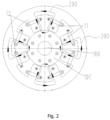
Fig. 2 is illustration of radial electromagnetic control magnetic circuits formed by a radial stator and radial control coils inFig. 1 ; -
Fig. 3 is illustration of an axial electromagnetic control magnetic circuit and an axial permanent magnet control magnetic circuit formed by axial stators and axial control coils and permanent magnets inFig. 1 ; and -
Fig. 4 is illustration of magnetic circuits inFig. 3 in combination with the radial electromagnetic control magnetic circuits. - 1 - radial stator; 11 - stator tooth; 12 - radial control coil; 2 - axial stator; 21 - first annular groove; 22 - axial control coil; 23 - second annular groove; 24 - permanent magnet; 100 - rotating shaft; 101 - rotor; 200 - radial electromagnetic control magnetic circuit; 301 - axial electromagnetic control magnetic circuit; 302 - axial permanent magnetic control magnetic circuit.
- Referring to
Figs. 1 to 4 , according to an embodiment of the present disclosure, there is provided a magnetic bearing, in particular a three-degree-of-freedom magnetic bearing, which includes a housing (not shown in the figures) with a radial stator 1 arranged therein. The radial stator 1 has a plurality ofstator teeth 11 extending inwardly in a radial direction thereof. Twoaxial stators 2 are arranged on two axial sides of thestator teeth 11, respectively.Radial control coils 12 are wound on thestator teeth 11. Theradial control coils 12 are located outside an area of thestator teeth 11 covered oppositely by the twoaxial stators 2, i.e., an outer diameter of theaxial stators 2 is smaller than an inner diameter of a ring formed theradial control coils 12. In this technical solution, arranging theradial control coils 12 outside the area of thestator teeth 11 covered oppositely by the twoaxial stators 2 allows, in terms of physical structure, corresponding radial electromagnetic controlmagnetic circuits 200 generated by theradial control coils 12 not to pass through theaxial stators 2, thereby effectively reducing the degree of coupling between the radial electromagnetic controlmagnetic circuits 200 on theaxial stators 2 and an axial electromagnetic controlmagnetic circuit 301, thus reducing the control difficulty of the magnetic bearing. - As shown in
Fig. 2 , the plurality ofstator teeth 11 are uniformly spaced circumferentially of the radial stator 1, and the number of thestator teeth 11 is 2N, where N ≥ 2, and current directions in theradial control coils 12 on every adjacent twostator teeth 11 are just opposite to form a closed loop of the radial electromagnetic controlmagnetic circuit 200 between the adjacent twostator teeth 11 and arotor 101. - As a specific structural form of the
axial stator 2, in an embodiment, theaxial stator 2 is provided with a firstannular groove 21 on a side facing thestator teeth 11. Anaxial control coil 22 is arranged in the firstannular groove 21. That is, theaxial control coil 22 is arranged circumferentially of a rotatingshaft 100, which may also be construed as being wound circumferentially of therotor 101, thereby simplifying the winding process of the coil. - In an embodiment, the axial stator is 2 is further provided with a second
annular groove 23 on the side facing thestator teeth 11. Apermanent magnet 24 is arranged in the secondannular groove 23. Thepermanent magnet 24 is provided for the purpose of providing a bias magnetic field, i.e., providing a magnetic field that keeps therotor 101 statically centered. This magnetic field is an axial permanent magnet controlmagnetic circuit 302. On the basis of this magnetic field, when the strength of the axial electromagnetic control magnetic circuit 301 (the strength of a current in the axial control coil 22) is changed, the position of therotor 101 can be adjusted by theaxial control coils 22 in the twoaxial stators 2. - As shown in
Figs. 3 and4 , current directions of theaxial control coils 22 on the two axial sides of thestator teeth 11 are same. In an embodiment, the firstannular groove 21 has a first groove wall close to an axis of theaxial stator 2, the first groove wall having a diameter D. When the magnetic bearing is assembled with therotating shaft 100, therotor 101 of the rotatingshaft 100 has an outer diameter d, where d ≥ D, so that the axial electromagnetic controlmagnetic circuit 301 can pass through theaxial stator 2 on one side to therotor 101, then to theaxial stator 2 on the other side, and then through the radial stator 1 and back to theaxial stator 2 on the one side, to form a magnetic circuit closed loop. At this point, it can be understood that although both the axialelectromagnetic control circuit 301 and the radialelectromagnetic control circuit 200 spatially pass through the radial stator 1, the degree of magnetic circuit coupling is extremely low because the two magnetic circuits are actually crossed in a three-dimensional space; furthermore, the axialelectromagnetic control circuit 301 in this case does not pass through an air gap between the radial stator 1 and therotor 101 and thus is not coupled with the radialelectromagnetic control circuit 200 at the air gap. - In an embodiment, the second
annular groove 23 has an outer diameter H, where H < D. In an embodiment, thepermanent magnet 24 is a plurality ofpermanent magnets 24 of tile-shaped structures arranged within the secondannular groove 23. In an embodiment, thepermanent magnet 24 is an annular permanent magnet, and/or thepermanent magnet 24 is in interference fit with the secondannular groove 23. - According to a specific embodiment of the present disclosure, a compressor is also provided, which includes the above-mentioned magnetic bearing.
- According to a specific embodiment of the present disclosure, an air conditioner is also provided, which includes the above-mentioned compressor.
- It is readily understood by those skilled in the art that the advantageous implementations described above can be freely combined and superimposed without conflict.
- The invention is defined by the scope of the appended claims.
Claims (9)
- A magnetic bearing and rotating shaft assembly, comprising:a radial stator (1) having a plurality of stator teeth (11) extending inwardly in a radial direction of the radial stator (1);two axial stators (2) arranged on two axial sides of the stator teeth (11), respectively;radial control coils (12) wound on the stator teeth (11), the radial control coil (12) being located outside an area of the stator teeth (11) covered oppositely by the two axial stators (2);characterized in thatthe axial stator (2) is configured with a first annular groove (21) on a side facing the stator teeth (11), and the magnetic bearing further comprises axial control coils (22) arranged in the first annular grooves (21), and the first annular groove (21) has a first groove wall close to an axis of the axial stator (2), the first groove wall having a diameter D, and the magnetic bearing is assembled with a rotating shaft (100) with a rotor (101) having an outer diameter d, where d ≥ D
- The magnetic bearing and rotating shaft assembly according to claim 1, wherein the plurality of stator teeth (11) are uniformly spaced circumferentially of the radial stator (1), and the number of the stator teeth (11) is 2N, where N ≥ 2.
- The magnetic bearing and rotating shaft assembly according to claim 1, wherein current directions of the axial control coils (22) on the two axial sides of the stator teeth (11) are same.
- The magnetic bearing and rotating shaft assembly according to claim 1, wherein the axial stator (2) is further provided with a second annular groove (23) on the side facing the stator teeth (11), and the magnetic bearing further comprises permanent magnets (24) arranged in the second annular grooves (23).
- The magnetic bearing and rotating shaft assembly according to claim 4, wherein the second annular grooves (23) have an outer diameter H, where H<D.
- The magnetic bearing and rotating shaft assembly according to claim 4, wherein the permanent magnets (24) are annular
- The magnetic bearing and rotating shaft assembly according to claim 4 or 6, wherein the permanent magnets (24) are in interference fit with the second annular grooves (23).
- A compressor, comprising a magnetic bearing, the magnetic bearing comprising:a radial stator (1) having a plurality of stator teeth (11) extending inwardly in a radial direction of the radial stator (1);two axial stators (2) arranged on two axial sides of the stator teeth (11), respectively;radial control coils (12) wound on the stator teeth (11), the radial control coils (12) being located outside an area of the stator teeth (11) covered oppositely by the two axial stators (2); andwherein the axial stator (2) is configured with a first annular groove (21) on a side facing the stator teeth (11), and the magnetic bearing further comprises axial control coils (22) arranged in the first annular grooves (21), and the first annular groove (21) has a first groove wall close to an axis of the axial stator (2), the first groove wall having a diameter D, and the magnetic bearing is provided to be assembled with a rotating shaft (100) with a rotor (101) having an outer diameter d, where d ≥ D.
- An air conditioner, comprising a compressor comprising a magnetic bearing, the magnetic bearing comprising:a radial stator (1) having a plurality of stator teeth (11) extending inwardly in a radial direction of the radial stator (1);two axial stators (2) arranged on two axial sides of the stator teeth (11), respectively;a radial control coil (12) wound on the stator teeth (11), the radial control coil (12) being located outside an area of the stator teeth (11) covered oppositely by the two axial stators (2); andwherein the axial stator (2) is configured with a first annular groove (21) on a side facing the stator teeth (11), and the magnetic bearing further comprises axial control coils (22) arranged in the first annular grooves (21), and the first annular groove (21) has a first groove wall close to an axis of the axial stator (2), the first groove wall having a diameter D, and the magnetic bearing is provided to be assembled with a rotating shaft (100) with a rotor (101) having an outer diameter d, where d ≥ D.
Applications Claiming Priority (2)
| Application Number | Priority Date | Filing Date | Title |
|---|---|---|---|
| CN201911411355.9A CN111102291B (en) | 2019-12-31 | Magnetic suspension bearing, compressor and air conditioner | |
| PCT/CN2020/110800 WO2021135276A1 (en) | 2019-12-31 | 2020-08-24 | Magnetic suspension bearing, compressor, and air conditioner |
Publications (3)
| Publication Number | Publication Date |
|---|---|
| EP4086470A1 EP4086470A1 (en) | 2022-11-09 |
| EP4086470A4 EP4086470A4 (en) | 2023-01-25 |
| EP4086470B1 true EP4086470B1 (en) | 2023-10-25 |
Family
ID=70424029
Family Applications (1)
| Application Number | Title | Priority Date | Filing Date |
|---|---|---|---|
| EP20910748.1A Active EP4086470B1 (en) | 2019-12-31 | 2020-08-24 | Magnetic suspension bearing, compressor, and air conditioner |
Country Status (3)
| Country | Link |
|---|---|
| US (1) | US11905994B2 (en) |
| EP (1) | EP4086470B1 (en) |
| WO (1) | WO2021135276A1 (en) |
Family Cites Families (14)
| Publication number | Priority date | Publication date | Assignee | Title |
|---|---|---|---|---|
| FR2756335B1 (en) * | 1996-11-25 | 1999-02-12 | Aerospatiale | MAGNETIC BEARING LONGITUDINALLY AND TRANSVERSELY ACTIVE |
| EP1333558A3 (en) * | 2002-01-31 | 2005-01-26 | Hitachi, Ltd. | Rotor for rotating electric machine and method of fabricating the same, for gas turbine power plant |
| CN101220832B (en) * | 2007-11-28 | 2010-06-09 | 江苏大学 | Radial-axial mixed magnetic bearing driven by radial quadrupole biphase alternating current |
| JP5845874B2 (en) | 2011-12-16 | 2016-01-20 | ダイキン工業株式会社 | Rotating body |
| CN102900761B (en) * | 2012-09-06 | 2014-12-24 | 江苏大学 | Permanent magnet biased axial hybrid magnetic bearing |
| CN202883726U (en) | 2012-09-06 | 2013-04-17 | 江苏大学 | Permanent magnet bias magnet axial mixed magnetic bearing |
| CN103490572B (en) * | 2013-05-28 | 2016-08-24 | 南京航空航天大学 | A kind of three-degree-of-freemagnetic magnetic suspension switch reluctance motor |
| CN103441630B (en) | 2013-06-20 | 2015-12-02 | 南京航空航天大学 | A kind of three-degree-of-freemagnetic magnetic suspension switch reluctance motor of 12/4 electrode structure |
| CN105610288B (en) * | 2016-01-26 | 2018-02-27 | 江苏大学 | A kind of permanent-magnet torque and reluctance torque divergence type motor and optimum efficiency control method |
| CN106050918B (en) | 2016-06-08 | 2019-05-24 | 淮阴工学院 | A kind of permanent magnet bias five degree of freedom integrated magnetic suspension support system |
| CN105864292B (en) * | 2016-06-08 | 2019-05-31 | 淮阴工学院 | A kind of permanent magnet bias Three Degree Of Freedom magnetic bearing |
| CN107579637A (en) | 2017-08-17 | 2018-01-12 | 东南大学 | A kind of axial radial flux magneto |
| CN108547868B (en) * | 2018-04-12 | 2020-02-07 | 南京邮电大学 | Semi-freedom degree radial magnetizing hybrid axial magnetic bearing |
| CN211550276U (en) | 2019-12-31 | 2020-09-22 | 珠海格力电器股份有限公司 | Magnetic suspension bearing, compressor and air conditioner |
-
2020
- 2020-08-24 EP EP20910748.1A patent/EP4086470B1/en active Active
- 2020-08-24 US US17/765,329 patent/US11905994B2/en active Active
- 2020-08-24 WO PCT/CN2020/110800 patent/WO2021135276A1/en unknown
Also Published As
| Publication number | Publication date |
|---|---|
| EP4086470A4 (en) | 2023-01-25 |
| WO2021135276A1 (en) | 2021-07-08 |
| EP4086470A1 (en) | 2022-11-09 |
| US20220333644A1 (en) | 2022-10-20 |
| US11905994B2 (en) | 2024-02-20 |
| CN111102291A (en) | 2020-05-05 |
Similar Documents
| Publication | Publication Date | Title |
|---|---|---|
| CN102305242B (en) | Radial-axial three-degree-of-freedom alternating current-direct current hybrid magnetic bearing | |
| CN102377298B (en) | Five-degree-of-freedom (five-DOF) bearing-free permanent magnet synchronous motor | |
| CN108825655A (en) | A kind of radial-axial Three Degree Of Freedom magnetic bearing with magnetism-isolating loop | |
| CN108448808B (en) | Permanent magnet type magnetic suspension switched reluctance flywheel motor with sleeve pole shoe teeth axial split phase | |
| CN115654011A (en) | Magnetic suspension active three-degree-of-freedom bearing, motor and compressor | |
| CN108757731A (en) | A kind of radial-axial Three Degree Of Freedom magnetic bearing of permanent magnet axial magnetized | |
| JP3850195B2 (en) | Magnetic levitation motor | |
| CN113839516A (en) | Stator module for axial suspension, magnetic suspension motor and linear electromagnetic actuating mechanism | |
| CN112065856B (en) | Four-pole internal and external double-rotor hybrid magnetic bearing | |
| CN211623964U (en) | Permanent magnet bias type magnetic suspension bearing | |
| CN112671158A (en) | Hybrid magnetic suspension bearing, motor and air conditioner | |
| CN111043156B (en) | Novel structure crossed tooth quadrupole hybrid magnetic bearing | |
| CN211550276U (en) | Magnetic suspension bearing, compressor and air conditioner | |
| CN111173838B (en) | Radial uncoupled three-degree-of-freedom direct current hybrid magnetic bearing | |
| EP4086470B1 (en) | Magnetic suspension bearing, compressor, and air conditioner | |
| CN115654016B (en) | Magnetic suspension active bearing, motor and compressor | |
| CN218913478U (en) | Magnetic suspension active three-degree-of-freedom bearing, motor and compressor | |
| CN109681525B (en) | Magnetic suspension bearing and motor | |
| CN111102291B (en) | Magnetic suspension bearing, compressor and air conditioner | |
| CN112983988B (en) | Composite magnetic suspension bearing and magnetic suspension bearing system | |
| CN105048879A (en) | Magnetic-circuit-decoupling magnetic-bias active and passive integration radial magnetic suspension bearing | |
| CN212564072U (en) | Non-contact hybrid magnetic bearing with internal stator and external stator | |
| CN112003418B (en) | Magnetic suspension bearing, assembling method thereof and motor | |
| CN112065853A (en) | Outer winding controlled inner and outer double-rotor hybrid magnetic bearing | |
| CN102297202B (en) | Single shaft controlled type five-degrees-of-freedom (DOF) miniature magnetic bearing |
Legal Events
| Date | Code | Title | Description |
|---|---|---|---|
| STAA | Information on the status of an ep patent application or granted ep patent |
Free format text: STATUS: THE INTERNATIONAL PUBLICATION HAS BEEN MADE |
|
| PUAI | Public reference made under article 153(3) epc to a published international application that has entered the european phase |
Free format text: ORIGINAL CODE: 0009012 |
|
| STAA | Information on the status of an ep patent application or granted ep patent |
Free format text: STATUS: REQUEST FOR EXAMINATION WAS MADE |
|
| 17P | Request for examination filed |
Effective date: 20220310 |
|
| AK | Designated contracting states |
Kind code of ref document: A1 Designated state(s): AL AT BE BG CH CY CZ DE DK EE ES FI FR GB GR HR HU IE IS IT LI LT LU LV MC MK MT NL NO PL PT RO RS SE SI SK SM TR |
|
| A4 | Supplementary search report drawn up and despatched |
Effective date: 20221223 |
|
| RIC1 | Information provided on ipc code assigned before grant |
Ipc: F25B 1/00 20060101ALI20221219BHEP Ipc: F04B 39/00 20060101ALI20221219BHEP Ipc: F16C 32/04 20060101AFI20221219BHEP |
|
| DAV | Request for validation of the european patent (deleted) | ||
| DAX | Request for extension of the european patent (deleted) | ||
| P01 | Opt-out of the competence of the unified patent court (upc) registered |
Effective date: 20230530 |
|
| RIC1 | Information provided on ipc code assigned before grant |
Ipc: F25B 1/00 20060101ALI20230628BHEP Ipc: F04B 39/00 20060101ALI20230628BHEP Ipc: F16C 32/04 20060101AFI20230628BHEP |
|
| GRAP | Despatch of communication of intention to grant a patent |
Free format text: ORIGINAL CODE: EPIDOSNIGR1 |
|
| STAA | Information on the status of an ep patent application or granted ep patent |
Free format text: STATUS: GRANT OF PATENT IS INTENDED |
|
| INTG | Intention to grant announced |
Effective date: 20230810 |
|
| GRAS | Grant fee paid |
Free format text: ORIGINAL CODE: EPIDOSNIGR3 |
|
| GRAA | (expected) grant |
Free format text: ORIGINAL CODE: 0009210 |
|
| STAA | Information on the status of an ep patent application or granted ep patent |
Free format text: STATUS: THE PATENT HAS BEEN GRANTED |
|
| AK | Designated contracting states |
Kind code of ref document: B1 Designated state(s): AL AT BE BG CH CY CZ DE DK EE ES FI FR GB GR HR HU IE IS IT LI LT LU LV MC MK MT NL NO PL PT RO RS SE SI SK SM TR |
|
| REG | Reference to a national code |
Ref country code: GB Ref legal event code: FG4D |
|
| REG | Reference to a national code |
Ref country code: CH Ref legal event code: EP |
|
| REG | Reference to a national code |
Ref country code: DE Ref legal event code: R096 Ref document number: 602020020036 Country of ref document: DE |
|
| REG | Reference to a national code |
Ref country code: IE Ref legal event code: FG4D |
|
| REG | Reference to a national code |
Ref country code: LT Ref legal event code: MG9D |
|
| REG | Reference to a national code |
Ref country code: NL Ref legal event code: MP Effective date: 20231025 |
|
| REG | Reference to a national code |
Ref country code: AT Ref legal event code: MK05 Ref document number: 1624934 Country of ref document: AT Kind code of ref document: T Effective date: 20231025 |
|
| PG25 | Lapsed in a contracting state [announced via postgrant information from national office to epo] |
Ref country code: NL Free format text: LAPSE BECAUSE OF FAILURE TO SUBMIT A TRANSLATION OF THE DESCRIPTION OR TO PAY THE FEE WITHIN THE PRESCRIBED TIME-LIMIT Effective date: 20231025 |
|
| PG25 | Lapsed in a contracting state [announced via postgrant information from national office to epo] |
Ref country code: GR Free format text: LAPSE BECAUSE OF FAILURE TO SUBMIT A TRANSLATION OF THE DESCRIPTION OR TO PAY THE FEE WITHIN THE PRESCRIBED TIME-LIMIT Effective date: 20240126 |
|
| PG25 | Lapsed in a contracting state [announced via postgrant information from national office to epo] |
Ref country code: IS Free format text: LAPSE BECAUSE OF FAILURE TO SUBMIT A TRANSLATION OF THE DESCRIPTION OR TO PAY THE FEE WITHIN THE PRESCRIBED TIME-LIMIT Effective date: 20240225 |
|
| PG25 | Lapsed in a contracting state [announced via postgrant information from national office to epo] |
Ref country code: LT Free format text: LAPSE BECAUSE OF FAILURE TO SUBMIT A TRANSLATION OF THE DESCRIPTION OR TO PAY THE FEE WITHIN THE PRESCRIBED TIME-LIMIT Effective date: 20231025 |
|
| PG25 | Lapsed in a contracting state [announced via postgrant information from national office to epo] |
Ref country code: AT Free format text: LAPSE BECAUSE OF FAILURE TO SUBMIT A TRANSLATION OF THE DESCRIPTION OR TO PAY THE FEE WITHIN THE PRESCRIBED TIME-LIMIT Effective date: 20231025 |
|
| PG25 | Lapsed in a contracting state [announced via postgrant information from national office to epo] |
Ref country code: ES Free format text: LAPSE BECAUSE OF FAILURE TO SUBMIT A TRANSLATION OF THE DESCRIPTION OR TO PAY THE FEE WITHIN THE PRESCRIBED TIME-LIMIT Effective date: 20231025 |
|
| PG25 | Lapsed in a contracting state [announced via postgrant information from national office to epo] |
Ref country code: LT Free format text: LAPSE BECAUSE OF FAILURE TO SUBMIT A TRANSLATION OF THE DESCRIPTION OR TO PAY THE FEE WITHIN THE PRESCRIBED TIME-LIMIT Effective date: 20231025 Ref country code: IS Free format text: LAPSE BECAUSE OF FAILURE TO SUBMIT A TRANSLATION OF THE DESCRIPTION OR TO PAY THE FEE WITHIN THE PRESCRIBED TIME-LIMIT Effective date: 20240225 Ref country code: GR Free format text: LAPSE BECAUSE OF FAILURE TO SUBMIT A TRANSLATION OF THE DESCRIPTION OR TO PAY THE FEE WITHIN THE PRESCRIBED TIME-LIMIT Effective date: 20240126 Ref country code: ES Free format text: LAPSE BECAUSE OF FAILURE TO SUBMIT A TRANSLATION OF THE DESCRIPTION OR TO PAY THE FEE WITHIN THE PRESCRIBED TIME-LIMIT Effective date: 20231025 Ref country code: BG Free format text: LAPSE BECAUSE OF FAILURE TO SUBMIT A TRANSLATION OF THE DESCRIPTION OR TO PAY THE FEE WITHIN THE PRESCRIBED TIME-LIMIT Effective date: 20240125 Ref country code: AT Free format text: LAPSE BECAUSE OF FAILURE TO SUBMIT A TRANSLATION OF THE DESCRIPTION OR TO PAY THE FEE WITHIN THE PRESCRIBED TIME-LIMIT Effective date: 20231025 Ref country code: PT Free format text: LAPSE BECAUSE OF FAILURE TO SUBMIT A TRANSLATION OF THE DESCRIPTION OR TO PAY THE FEE WITHIN THE PRESCRIBED TIME-LIMIT Effective date: 20240226 |
|
| PG25 | Lapsed in a contracting state [announced via postgrant information from national office to epo] |
Ref country code: SE Free format text: LAPSE BECAUSE OF FAILURE TO SUBMIT A TRANSLATION OF THE DESCRIPTION OR TO PAY THE FEE WITHIN THE PRESCRIBED TIME-LIMIT Effective date: 20231025 Ref country code: RS Free format text: LAPSE BECAUSE OF FAILURE TO SUBMIT A TRANSLATION OF THE DESCRIPTION OR TO PAY THE FEE WITHIN THE PRESCRIBED TIME-LIMIT Effective date: 20231025 Ref country code: PL Free format text: LAPSE BECAUSE OF FAILURE TO SUBMIT A TRANSLATION OF THE DESCRIPTION OR TO PAY THE FEE WITHIN THE PRESCRIBED TIME-LIMIT Effective date: 20231025 Ref country code: NO Free format text: LAPSE BECAUSE OF FAILURE TO SUBMIT A TRANSLATION OF THE DESCRIPTION OR TO PAY THE FEE WITHIN THE PRESCRIBED TIME-LIMIT Effective date: 20240125 Ref country code: LV Free format text: LAPSE BECAUSE OF FAILURE TO SUBMIT A TRANSLATION OF THE DESCRIPTION OR TO PAY THE FEE WITHIN THE PRESCRIBED TIME-LIMIT Effective date: 20231025 Ref country code: HR Free format text: LAPSE BECAUSE OF FAILURE TO SUBMIT A TRANSLATION OF THE DESCRIPTION OR TO PAY THE FEE WITHIN THE PRESCRIBED TIME-LIMIT Effective date: 20231025 |
|
| PG25 | Lapsed in a contracting state [announced via postgrant information from national office to epo] |
Ref country code: DK Free format text: LAPSE BECAUSE OF FAILURE TO SUBMIT A TRANSLATION OF THE DESCRIPTION OR TO PAY THE FEE WITHIN THE PRESCRIBED TIME-LIMIT Effective date: 20231025 |
|
| PG25 | Lapsed in a contracting state [announced via postgrant information from national office to epo] |
Ref country code: CZ Free format text: LAPSE BECAUSE OF FAILURE TO SUBMIT A TRANSLATION OF THE DESCRIPTION OR TO PAY THE FEE WITHIN THE PRESCRIBED TIME-LIMIT Effective date: 20231025 |
|
| REG | Reference to a national code |
Ref country code: DE Ref legal event code: R097 Ref document number: 602020020036 Country of ref document: DE |
|
| PG25 | Lapsed in a contracting state [announced via postgrant information from national office to epo] |
Ref country code: SK Free format text: LAPSE BECAUSE OF FAILURE TO SUBMIT A TRANSLATION OF THE DESCRIPTION OR TO PAY THE FEE WITHIN THE PRESCRIBED TIME-LIMIT Effective date: 20231025 |
|
| PG25 | Lapsed in a contracting state [announced via postgrant information from national office to epo] |
Ref country code: SM Free format text: LAPSE BECAUSE OF FAILURE TO SUBMIT A TRANSLATION OF THE DESCRIPTION OR TO PAY THE FEE WITHIN THE PRESCRIBED TIME-LIMIT Effective date: 20231025 Ref country code: SK Free format text: LAPSE BECAUSE OF FAILURE TO SUBMIT A TRANSLATION OF THE DESCRIPTION OR TO PAY THE FEE WITHIN THE PRESCRIBED TIME-LIMIT Effective date: 20231025 Ref country code: RO Free format text: LAPSE BECAUSE OF FAILURE TO SUBMIT A TRANSLATION OF THE DESCRIPTION OR TO PAY THE FEE WITHIN THE PRESCRIBED TIME-LIMIT Effective date: 20231025 Ref country code: IT Free format text: LAPSE BECAUSE OF FAILURE TO SUBMIT A TRANSLATION OF THE DESCRIPTION OR TO PAY THE FEE WITHIN THE PRESCRIBED TIME-LIMIT Effective date: 20231025 Ref country code: EE Free format text: LAPSE BECAUSE OF FAILURE TO SUBMIT A TRANSLATION OF THE DESCRIPTION OR TO PAY THE FEE WITHIN THE PRESCRIBED TIME-LIMIT Effective date: 20231025 Ref country code: DK Free format text: LAPSE BECAUSE OF FAILURE TO SUBMIT A TRANSLATION OF THE DESCRIPTION OR TO PAY THE FEE WITHIN THE PRESCRIBED TIME-LIMIT Effective date: 20231025 Ref country code: CZ Free format text: LAPSE BECAUSE OF FAILURE TO SUBMIT A TRANSLATION OF THE DESCRIPTION OR TO PAY THE FEE WITHIN THE PRESCRIBED TIME-LIMIT Effective date: 20231025 |
|
| PLBE | No opposition filed within time limit |
Free format text: ORIGINAL CODE: 0009261 |
|
| STAA | Information on the status of an ep patent application or granted ep patent |
Free format text: STATUS: NO OPPOSITION FILED WITHIN TIME LIMIT |