EP4084494B1 - Kopfhörer mit ohrhöreranordnung mit mehrstufiger geräuschunterdrückung - Google Patents
Kopfhörer mit ohrhöreranordnung mit mehrstufiger geräuschunterdrückung Download PDFInfo
- Publication number
- EP4084494B1 EP4084494B1 EP21218119.2A EP21218119A EP4084494B1 EP 4084494 B1 EP4084494 B1 EP 4084494B1 EP 21218119 A EP21218119 A EP 21218119A EP 4084494 B1 EP4084494 B1 EP 4084494B1
- Authority
- EP
- European Patent Office
- Prior art keywords
- earphone
- headphone
- ear
- cancellation
- earmuff
- Prior art date
- Legal status (The legal status is an assumption and is not a legal conclusion. Google has not performed a legal analysis and makes no representation as to the accuracy of the status listed.)
- Active
Links
Images


Classifications
-
- H—ELECTRICITY
- H04—ELECTRIC COMMUNICATION TECHNIQUE
- H04R—LOUDSPEAKERS, MICROPHONES, GRAMOPHONE PICK-UPS OR LIKE ACOUSTIC ELECTROMECHANICAL TRANSDUCERS; ELECTRIC HEARING AIDS; PUBLIC ADDRESS SYSTEMS
- H04R1/00—Details of transducers, loudspeakers or microphones
- H04R1/10—Earpieces; Attachments therefor ; Earphones; Monophonic headphones
- H04R1/1083—Reduction of ambient noise
-
- G—PHYSICS
- G10—MUSICAL INSTRUMENTS; ACOUSTICS
- G10K—SOUND-PRODUCING DEVICES; METHODS OR DEVICES FOR PROTECTING AGAINST, OR FOR DAMPING, NOISE OR OTHER ACOUSTIC WAVES IN GENERAL; ACOUSTICS NOT OTHERWISE PROVIDED FOR
- G10K11/00—Methods or devices for transmitting, conducting or directing sound in general; Methods or devices for protecting against, or for damping, noise or other acoustic waves in general
- G10K11/16—Methods or devices for protecting against, or for damping, noise or other acoustic waves in general
- G10K11/175—Methods or devices for protecting against, or for damping, noise or other acoustic waves in general using interference effects; Masking sound
- G10K11/178—Methods or devices for protecting against, or for damping, noise or other acoustic waves in general using interference effects; Masking sound by electro-acoustically regenerating the original acoustic waves in anti-phase
- G10K11/1781—Methods or devices for protecting against, or for damping, noise or other acoustic waves in general using interference effects; Masking sound by electro-acoustically regenerating the original acoustic waves in anti-phase characterised by the analysis of input or output signals, e.g. frequency range, modes, transfer functions
- G10K11/17821—Methods or devices for protecting against, or for damping, noise or other acoustic waves in general using interference effects; Masking sound by electro-acoustically regenerating the original acoustic waves in anti-phase characterised by the analysis of input or output signals, e.g. frequency range, modes, transfer functions characterised by the analysis of the input signals only
-
- H—ELECTRICITY
- H04—ELECTRIC COMMUNICATION TECHNIQUE
- H04R—LOUDSPEAKERS, MICROPHONES, GRAMOPHONE PICK-UPS OR LIKE ACOUSTIC ELECTROMECHANICAL TRANSDUCERS; ELECTRIC HEARING AIDS; PUBLIC ADDRESS SYSTEMS
- H04R1/00—Details of transducers, loudspeakers or microphones
- H04R1/10—Earpieces; Attachments therefor ; Earphones; Monophonic headphones
- H04R1/1008—Earpieces of the supra-aural or circum-aural type
-
- H—ELECTRICITY
- H04—ELECTRIC COMMUNICATION TECHNIQUE
- H04R—LOUDSPEAKERS, MICROPHONES, GRAMOPHONE PICK-UPS OR LIKE ACOUSTIC ELECTROMECHANICAL TRANSDUCERS; ELECTRIC HEARING AIDS; PUBLIC ADDRESS SYSTEMS
- H04R1/00—Details of transducers, loudspeakers or microphones
- H04R1/10—Earpieces; Attachments therefor ; Earphones; Monophonic headphones
- H04R1/1016—Earpieces of the intra-aural type
-
- H—ELECTRICITY
- H04—ELECTRIC COMMUNICATION TECHNIQUE
- H04R—LOUDSPEAKERS, MICROPHONES, GRAMOPHONE PICK-UPS OR LIKE ACOUSTIC ELECTROMECHANICAL TRANSDUCERS; ELECTRIC HEARING AIDS; PUBLIC ADDRESS SYSTEMS
- H04R1/00—Details of transducers, loudspeakers or microphones
- H04R1/10—Earpieces; Attachments therefor ; Earphones; Monophonic headphones
- H04R1/1025—Accumulators specially adapted for earpieces; Arrangements specially adapted for charging thereof
-
- H—ELECTRICITY
- H04—ELECTRIC COMMUNICATION TECHNIQUE
- H04R—LOUDSPEAKERS, MICROPHONES, GRAMOPHONE PICK-UPS OR LIKE ACOUSTIC ELECTROMECHANICAL TRANSDUCERS; ELECTRIC HEARING AIDS; PUBLIC ADDRESS SYSTEMS
- H04R1/00—Details of transducers, loudspeakers or microphones
- H04R1/10—Earpieces; Attachments therefor ; Earphones; Monophonic headphones
- H04R1/105—Earpiece supports, e.g. ear hooks
-
- H—ELECTRICITY
- H04—ELECTRIC COMMUNICATION TECHNIQUE
- H04R—LOUDSPEAKERS, MICROPHONES, GRAMOPHONE PICK-UPS OR LIKE ACOUSTIC ELECTROMECHANICAL TRANSDUCERS; ELECTRIC HEARING AIDS; PUBLIC ADDRESS SYSTEMS
- H04R2420/00—Details of connection covered by H04R, not provided for in its groups
- H04R2420/07—Applications of wireless loudspeakers or wireless microphones
-
- H—ELECTRICITY
- H04—ELECTRIC COMMUNICATION TECHNIQUE
- H04R—LOUDSPEAKERS, MICROPHONES, GRAMOPHONE PICK-UPS OR LIKE ACOUSTIC ELECTROMECHANICAL TRANSDUCERS; ELECTRIC HEARING AIDS; PUBLIC ADDRESS SYSTEMS
- H04R2460/00—Details of hearing devices, i.e. of ear- or headphones covered by H04R1/10 or H04R5/033 but not provided for in any of their subgroups, or of hearing aids covered by H04R25/00 but not provided for in any of its subgroups
- H04R2460/01—Hearing devices using active noise cancellation
-
- H—ELECTRICITY
- H04—ELECTRIC COMMUNICATION TECHNIQUE
- H04R—LOUDSPEAKERS, MICROPHONES, GRAMOPHONE PICK-UPS OR LIKE ACOUSTIC ELECTROMECHANICAL TRANSDUCERS; ELECTRIC HEARING AIDS; PUBLIC ADDRESS SYSTEMS
- H04R2460/00—Details of hearing devices, i.e. of ear- or headphones covered by H04R1/10 or H04R5/033 but not provided for in any of their subgroups, or of hearing aids covered by H04R25/00 but not provided for in any of its subgroups
- H04R2460/11—Aspects relating to vents, e.g. shape, orientation, acoustic properties in ear tips of hearing devices to prevent occlusion
Definitions
- the present disclosure relates to a field of earphones, and more particularly to a headphone and a multi-stage noise-cancellation earphone assembly.
- a noise-cancellation earphone can be divided into two categories, one is a head-mounted earmuff that wraps the ear, and the other one is an in-ear earplug that is inserted into the ear. Regardless whether the former or the latter, passive noise-cancellation materials are used as much as possible to absorb noise so as to create a closed space, and then active noise-cancellation technology is used to cancel noise.
- the effects of the two categories are weak.
- the head-mounted earmuff has advantages of bone conduction reduction and long battery life.
- the in-ear earplug has a small sound space, which is more conducive to active noise cancellation.
- the noise-cancellation effect of the in-ear earplug is substantively the same as that of the head-mounted earmuff, but they both cannot achieve the mute effect desired by consumers.
- Document WO 2020/131963 A1 discloses a combination of an earmuff and an in-ear earphone for active noise cancellation.
- Each of documents KR 102 202 370 B1 and KR 2015 0000651 A discloses a headphone with protruding elements on the side of the headband facing the user's head when the headphone is worn.
- a headphone configured to be used in combination with an in-ear earphone, and includes: an earmuff configured to be fitted over an auricle; an earmuff pickup arranged on an outer side of the earmuff and configured to collect an environmental sound; and a first speaker arranged on an inner side of the earmuff and configured to perform at least one of following actions: playing a noise-cancellation sound corresponding to the environmental sound collected by the earmuff pickup, or playing an audio.
- the inner side of the earmuff and the auricle define an accommodating space for accommodating a part of the in-ear earphone exposed out of an external auditory canal.
- the headphone further includes: a skeleton, two ends of the skeleton being each connected to one earmuff; and a support body arranged on a side of the skeleton facing a user's head when the headphone is worn, and configured for preventing the skeleton from coming into contact with the head.
- the in-ear earphone includes a second speaker arranged at the in-ear end of the in-ear earphone and configured to play an audio.
- the in-ear earphone and the headphone are detachably connected.
- the in-ear earphone is configured as a wireless earphone.
- the technical solutions provided by the embodiments of the present disclosure may include the following beneficial effects.
- the headphone and the auricle define the accommodating space for accommodating the in-ear headphone.
- the headphone may be used separately or in combination with any in-ear headphone.
- the noise is canceled by the active or passive noise cancellation of the in-ear headphone as well as the active noise cancellation and the passive noise cancellation of the headphone, thus achieving a multi-stage noise cancellation and a better noise cancellation effect.
- the problem of insufficient noise cancellation is solved, and the noise cancellation effect is greatly improved.
- the current noise-cancellation technology includes active noise cancellation and passive noise cancellation.
- the active noise cancellation is to generate a reverse sound wave equal to an external noise through a noise-cancellation system to neutralize the noise, thereby achieving the noise-cancellation effect.
- the passive noise cancellation includes noise cancellation at a sound source, noise cancellation during propagation, and noise cancellation at the human ear.
- the passive noise cancellation at the human ear is mainly implemented by surrounding the ear to form a closed space, or using sound-insulating materials such as silicone earplugs to block the external noise.
- the passive noise cancellation since the working principle of a passive noise-cancellation earphone does not involve the processes of collection and calculation, the structure of the passive noise-cancellation headphone is simple and reliable, and its manufacturing requirement and technical content are relatively low. In addition, because the passive noise-cancellation earphone does not cause interference to the music itself, the sound quality of the passive noise-cancellation earphone is better than that of an active noise-cancellation headphone. Most importantly, the passive noise-cancellation earphone does not need a battery and can be used at any time. Therefore, this technology is widely applied to an in-ear earphone, and current various in-ear earphones are typical passive noise-cancellation earphones.
- the speaker also known as a horn, is an electro-acoustic device that can convert electrical energy into sound energy.
- the principle of the speaker is that a current passes through a coil in a magnetic circuit composed of magnets to generate driving forces in up and down directions to vibrate a vibrating body, and then the air vibrates to make a sound.
- the headphone 20 includes an earmuff 21.
- the earmuff 21 can be fitted over an in-ear earphone 10.
- the earmuff 21 is arranged at an auricle 51, and an accommodating space is defined between the earmuff 21 and the auricle 51 for accommodating a part of the in-ear earphone 10 exposed out of an external auditory canal 52.
- the earmuff 21 can be fitted over the auricle 51 and fitted with the auricle 51. Since the in-ear earphone 10 is inserted into the external auditory canal 52, when the earmuff 21 is arranged at the auricle 51, the in-ear earphone 10 is covered.
- the headphone 20 further includes a first speaker 22 arranged on an inner side of the earmuff 21, that is, the first speaker 22 is arranged at an end adjacent to the auricle 51.
- An audio played by the first speaker 22 causes the air in the external auditory canal 52 to vibrate, the vibration reaches a tympanic membrane to cause a mechanical movement of an ossicular chain, the vibration of a stapes footplate causes a movement of a vestibular window, the energy is transferred to inner and outer lymph fluids in a cochlea and becomes liquid vibration, the movement of hair cells on a basement membrane produces a bioelectrical activity, and nerve impulses reach the auditory cortex center along uploading nerve pathways by virtue of the auditory nerve to produce hearing.
- the headphone 20 can be detached, so that the in-ear earphone 10 can be used separately or the headphone 20 can be used separately.
- the pressure of the headphone 20 on the auricle 51 is small. Since the headphone 20 can be separated from the earphone 10 and used separately, the user can use different earphones in different environments. In a noisy and irregular environment, the user can choose the in-ear earphone 10, and the in-ear earphone 10 can partially blocks mid- frequency and high-frequency noises, but cannot obviously block low-frequency noise. In a relatively quiet and regular environment, the headphone 20 can be selected.
- the active noise cancellation can effectively cancel the low-frequency noise by more than 80%, and most of the noises in life is the low-frequency noise, such as environmental noises in e.g. buses, subways, high-speed rails, trains, cars, buses, airplanes, gyms, bars, etc.
- the low-frequency noise such as environmental noises in e.g. buses, subways, high-speed rails, trains, cars, buses, airplanes, gyms, bars, etc.
- the headphone 20 further includes: an air inlet, an air blower 24 and an air duct 30.
- the air inlet is arranged on the outer side of the earmuff 21, the air blower 24 is arranged on the earmuff 21 and in communication with the air inlet, and the air duct 30 is configured to communicate the air inlet with the in-ear earphone 10.
- the air duct 30 may allow the air outside the earmuff 21 to enter the in-ear earphone 10 and further enter the external auditory canal 52.
- the headphone 20 further includes a charging cable 40.
- the charging cable 40 is configured to connect the headphone 20 to a battery 15 of the in-ear earphone 10.
- the in-ear earphone 10 is provided with the battery 15, and power stored in the battery 15 can power the in-ear earphone 10.
- the in-ear earphone 10 enables an active noise-cancellation mode, both an earphone pickup 12 and the processing chip require power supply.
- the headphone further includes a charging cable 40, and the charging cable 40 can charge the battery 15 of the in-ear earphone 10. That is, one end of the charging cable 40 is connected to the in-ear earphone 10, and the other end of the charging cable 40 may be connected to a plug, or the other end of the charging cable 40 may also be connected to the headphone 20. In other words, the battery 15 of the in-ear earphone 10 can be charged by an external charging device. When the in-ear earphone 10 is used in combination with the headphone 20, the battery 15 of the in-ear earphone 10 may be charged by the headphone 20.
- the headphone 20 charges the battery 15 of the in-ear earphone 10
- the two ends of the charging cable 40 are respectively connected to the headphone 20 and the battery 15 of the in-ear earphone 10
- the two ends of the charging cable 40 can be separated from the headphone 20 and the earphone 10, which ensures the comfort and aesthetics of the headphone 20 and the earphone 10 when they are used separately.
- the headphone 20 in this case may be configured as a wireless earphone or a wired earphone.
- the headphone 20 when the in-ear earphone 10 is low in power, the headphone 20, as a supporting device, can be used as a power supply to charge the in-ear earphone 10. After being charged, the in-ear earphone 10 can be used separately; or, the headphone 20 can be used in combination with the in-ear earphone 10 while charging the in-ear earphone 10.
- the headphone 20 further includes a skeleton 25. Two ends of the skeleton 25 are each connected to one earmuff 21, and a side of the skeleton 25 facing the head is provided with a support body 26 for preventing the skeleton 25 from coming into contact with the head.
- the skeleton 25 for connection is often arranged between two earmuffs 21 of the headphone 20.
- the two ends of the skeleton 25 are each connected to one earmuff 21.
- the skeleton 25 is in contact with a head 50 of the user.
- the skeleton 25 can be hung on the neck of the user. Therefore, the skeleton 25 can prevent the earmuff 21 from sliding and falling off to be broken or lost under the action of gravity, or prevent the earmuff 21 from falling off due to strong vibration during exercise.
- the skeleton 25 since the skeleton 25 is in contact with the head 50 of the user, the skeleton 25 has an arc shape, and the bending radian of the skeleton 25 corresponds to the radian of the head 50 or the neck of the user, which can ensure the user's comfort.
- the skeleton 25 may have a flat structure, so that the contact area between the headphone 20 and the head 50 is large and the pressure is small.
- the skeleton 25 may be made of materials such as polystyrene, polyvinyl chloride, or polytetrafluoroethylene.
- the skeleton 25 has elasticity and a clamping force.
- the clamping force of the skeleton 25 allows the earmuffs 21 at the two ends of the skeleton 25 to be fitted with the auricle 51 of the ears more closely, so that a more closed space is formed between the earmuff 21 and the auricle 51, and thus a better passive noise-cancellation effect is achieved, thereby improving the user experience.
- the support body 26 is arranged on the side of the skeleton 25 facing the user's head 50.
- the support body 26 can separate the skeleton 25 from the user's head 50 by a certain distance without contact.
- the headphone 20 can be adapted to the head shapes of different users to become more fit and stable.
- the support body 26 ensures a distance between the skeleton 25 and the head 50, which can prevent the skeleton 25 from pressing against the head 50 and ruining the hairstyle, thereby solving the problem that the skeleton 25 crushes the hair and ruins the hairstyle.
- the distance between the skeleton 25 and the head 50 also helps to dissipate heat, and can also prevent the skeleton 25 from erosions by perspiration or the like on the user's head 50, so as to effectively prevent sweat erosion, thereby prolonging the service life of the skeleton 25.
- a side of the support body 26 in contact with the head 50 may have an arc shape which corresponds to the radian of the head 50.
- the support body 26 may be fixedly arranged on the skeleton 25 or may be detachably arranged on the skeleton 25.
- the user may also adjust the length of the support body 26 according to the intensity of exercise or the use temperature, that is, the distance between the skeleton 25 and the user's head 50 can be adjusted. By adjusting the length of the support body 26, the headphone 20 can be adapted to the heads 50 of different users.
- the user adjusts the length of the support body 26 according to the size or shape of the head 50, so that the head 50 can come into contact with the headphone 20 through three points, including two earmuffs 21 and one support body 26, and thus the user feels more comfortable and stable when wearing the headphone 20.
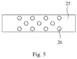
- the support body 26 includes a plurality of support pillars, and the plurality of support pillars are distributed on the skeleton 25 at intervals in an array. As shown in Fig. 2 , one end of each support column is arranged on the side of the skeleton 25 adjacent to the head 50, and the other end of the support column is provided with an arc-shaped ball. When the arc-shaped ball is in contact with the user's head 50, the user's head 50 can be prevented from being scratched by the support column.
- the support body 26 includes the plurality of support pillars which can increase the ventilation environment and save materials. As further shown in Fig. 5 which is an enlarged bottom view of part A in Fig.
- each support column may also be provided therein with a vibration motor which can cause the support column to vibrate.
- the plurality of vibrating support pillars in combination with the arc-shaped balls at the ends of the plurality of support pillars in contact with the head 50, can massage the scalp of the user's head 50.
- the support pillars are not of the same length, so that the ends of the plurality of support pillars adjacent to the head 50 form an arc surface corresponding to the head 50, thereby improving the comfort of the user.
- the headphone 20 further includes an earmuff-sealing ring 27 arranged at an end of a housing of the headphone 20 adjacent to the ear.
- the earmuff-sealing ring 27 has a filtering effect on sound.
- the earmuff-sealing ring 27 is arranged at the end of the headphone 20 adjacent to the ear.
- the earmuff-sealing ring 27 is soft and can be fitted with the skin of the auricle 51, so as to isolate a lot of noise from the outside, thus improving the sound quality experience.
- a multi-stage noise-cancellation earphone assembly is provided.
- the multi-stage noise-cancellation earphone assembly includes an in-ear earphone 10 and a headphone 20.
- the in-ear earphone 10 is located in the accommodating space defined by the headphone 20 and the auricle 51.
- the in-ear earphone 10 includes a second speaker 11 arranged at an in-ear end of the in-ear earphone 10 and configured to play an audio.
- the earmuff 21 of the headphone 20 is fitted with the auricle 51 of the human ear, thus achieving a function of physical noise cancellation, that is, the passive noise cancellation.
- the in-ear earphone 10 achieves an audio output function.
- the second speaker 11 is inserted into the external auditory canal 52 of the user.
- the audio played by the first speaker 22 causes the air in the external auditory canal 52 to vibrate, the vibration reaches a tympanic membrane to cause a mechanical movement of an ossicular chain, the vibration of the stapes footplate causes a movement of the vestibular window, the energy is transferred to inner and outer lymph fluids in a cochlea and becomes liquid vibration, the movement of hair cells on a basement membrane produces a bioelectrical activity, and nerve impulses reach the auditory cortex center along uploading nerve pathways by virtue of the auditory nerve to produce hearing.
- the earmuff pickup 23 of the headphone 20 can be combined with the first speaker 22, which may also achieve the function of active noise cancellation. Therefore, by the combination of the earmuff 21 of the headphone 20, the earmuff pickup 23 and the first speaker 22, both the passive noise cancellation and the active noise cancellation can be achieved at the same time.
- the passive noise cancellation of the headphone 20 physically provides a closed environment for the in-ear earphone 10 and hinders the interference of external noise.
- the active noise cancellation of the headphone 20 filters out part of the noise in the environment in advance for the in-ear earphone 10.
- the passive noise cancellation and the active noise cancellation of the headphone 20 With the passive noise cancellation of the in-ear earphone 10, the problem of insufficient noise cancellation is solved through the multi-stage superposition, and the noise-cancellation effect is greatly improved.
- the functions of the passive noise cancellation and the active noise cancellation of the headphone 20 itself can help the user avoid noise interference and adjust the mood.
- the headphone 20 isolates the noise damage to the eardrum.
- the in-ear earphone 10 further includes an earphone pickup 12.
- the working principle of the earphone pickup 12 is the same with the working principle of the earmuff pickup 23.
- the earphone pickup 12 may be configured to collect an environmental sound, and the second speaker 11 may also be configured to play a noise-cancellation sound corresponding to the environmental sound collected by the earphone pickup 12.
- the in-ear earphone 10 may include two modes, i.e. an active noise-cancellation mode and a passive noise-cancellation mode. When the in-ear earphone 10 is in the passive noise-cancellation mode, the active noise-cancellation mode is disabled. When the in-ear earphone 10 is in the active noise-cancellation mode, the active noise-cancellation mode is enabled.
- the earphone pickup 12 of the in-ear earphone 10 is located on a side away from the in-ear end.
- the earphone pickup 12 of the in-ear earphone 10 can collect the external environmental sound, a microphone of the earphone pickup 12 may sample the noise heard by the human ear and the sampled noise is then transmitted to a processing chip in the in-ear earphone 10 via a circuit board and a signal transmission cable of the earphone pickup 12.
- the processing chip reverses and amplifies the noise collected by the earphone pickup 12, and then drives the second speaker 11 to play an "anti-noise". Playing the "anti-noise" involves playing a noise-cancellation sound corresponding to the environmental sound collected by the earphone pickup 12, so as to cancel the noise transmitted from the outside into the human ear through the in-ear earphone 10.
- the in-ear earphone 10 When the in-ear earphone 10 is used in combination with the headphone 20, the in-ear earphone 10 may enable the active noise-cancellation mode, and the headphone 20 may also enable the active noise-cancellation mode; or, the in-ear earphone 10 may enable the active noise-cancellation mode and the headphone 20 adopts the passive noise-cancellation mode; or, the in-ear earphone 10 adopts the passive noise-cancellation mode and the headphone 20 enables the active noise-cancellation mode; or, both the in-ear earphone 10 and the headphone 20 adopt the passive noise-cancellation mode at the same time.
- the working process of the headphone 20 and the in-ear earphone 10 is as follows.
- the earmuff pickup 23 on the outer side of the earmuff 21 of the headphone 20 collects a sound in the external environmental of the earmuff 21.
- the first speaker 22 plays a sound in an opposite phase to the noise collected by the earmuff pickup 23 so as to neutralize the noise of the external environment.
- the earphone pickup 12 Since the in-ear earphone 10 is wrapped in the closed space defined by the headphone 20 and the auricle 51, the earphone pickup 12 is configured to collect a sound in the closed space.
- the sound in the closed space in this case is the sound obtained after the active noise-cancellation system of the headphone 20 neutralizes the noise of the external environment.
- the second speaker 11 plays a sound in an opposite phase to the noise collected by the earphone pickup 12 so as to neutralize the sound in the external environment and the closed space. In addition, the second speaker 11 also plays an audio sound selected by the user.
- Both the in-ear headphone 10 and the headphone 20 themselves have the function of passive noise cancellation. After both headphones enable the active noise cancellation, a four-stage noise cancellation is achieved by the active noise cancellation and the passive noise cancellation of the headphone 20 as well as the active noise cancellation and the passive noise cancellation of the in-ear headphone 10.
- the noise-cancellation process of the headphone 20 and the in-ear headphone 10 is as follows.
- the passive noise-cancellation material of the headphone 20 filters out part of the external noise.
- the earphone pickup 12 of the in-ear earphone 10 collects the sound in the closed space in this case.
- the second speaker 11 of the in-ear earphone 10 plays a sound in an opposite phase to the sound collected by the earphone pickup 12 and also plays an audio sound selected by the user.
- a three-stage noise cancellation is achieved by the passive noise cancellation of the headphone 20 as well as the active noise cancellation and the passive noise cancellation of the in-ear earphone 10.
- the noise-cancellation process of the headphone 20 and the in-ear earphone 10 is as follows.
- the earmuff pickup 23 of the headphone 20 collects the sound of the external environment.
- the first speaker 22 plays the noise-cancellation sound corresponding to the environmental sound collected by the earmuff pickup 23, so as to cancel the noise transmitted from the outside into the human ear through the earmuff 21.
- the passive noise cancellation is achieved by the passive noise-cancellation material of the in-ear earphone 10, and the second speaker 11 of the in-ear earphone 10 plays the audio sound selected by the user.
- a three-stage noise cancellation is achieved by the passive noise cancellation and the active noise cancellation of the headphone 20 as well as the passive noise cancellation of the in-ear earphone 10.
- the in-ear earphone 10 adopts the active noise-cancellation mode or the passive noise-cancellation mode and whether the headphone 20 adopts the active noise-cancellation mode or the passive noise-cancellation mode can be selected by the user at will according to the use environment, so as to achieve the multi-stage noise cancellation, which is not limited specifically herein.
- the above description is provided as specific embodiments for illustration, but should not be understood as limitation on the scope of the present disclosure.
- the in-ear earphone 10 and the headphone 20 are detachably connected. It can be seen from the above description that the in-ear earphone 10 may be configured as an earphone having the passive noise cancellation, or an earphone that combines the active noise cancellation and the passive noise cancellation. Similarly, the headphone 20 may also be configured as a headphone having the passive noise cancellation, or a headphone that combines the active noise cancellation and the passive noise cancellation. As mentioned above, the in-ear earphone 10 and the headphone 20 may be used as earphones separately or in combination.
- the headphone 20 When the in-ear earphone 10 and the headphone 20 are used in combination, the headphone 20 has the skeleton, and the two ends of the skeleton are each connected to one earmuff 21. Through the skeleton and the clamping force of the two earmuffs 21 on the auricle 51 of the head, a friction force is generated so that the headphone 20 is fixed at the auricle 51.
- the in-ear end of the in-ear earphone 10 is inserted into the external auditory canal 52 to achieve a fixing effect. Therefore, there may be no connector between the in-ear earphone 10 and the headphone 20.
- the detachable connection between the in-ear earphone 10 and the headphone 20 means that the in-ear earphone 10 and the headphone 20 can be connected together by a connector.
- the connector may be a flexible connector or a fixed connector.
- the flexible connector may be a flexible connecting wire or the like, and the fixed connector may refer to a snap joint connection, or the like.
- the connector allows the in-ear earphone 10 and the headphone 20 to be detachably connected.
- the two may be integrated to prevent one of them from falling and hence affecting the noise-cancellation effect.
- the connector also brings convenience for storage and arrangement.
- the two earphones may be stored in one place, thereby preventing the headphone 20 or the in-ear earphone 10 from being lost due to separate placement.
- the in-ear earphone 10 further includes an air intake port, an air channel and an air exhaust port 13.
- the air intake port is arranged at a rear end opposite to the in-ear end, the air exhaust port 13 is arranged at the in-ear end, and the air channel communicates the air intake port with the air exhaust port 13.
- An earphone body of the in-ear earphone 10 is provided with the air intake port and the air exhaust port 13, and the air intake port and the air exhaust port 13 are communicated by the air channel.
- the air intake port and the air exhaust port 13 are both located in the earphone body of the in-ear earphone 10.
- the air exhaust port 13 is located at the in-ear end of the in-ear earphone 10. When the in-ear earphone 10 is inserted into the external ear canal 52, the air exhaust port 13 also enters the external auditory canal 52 together.
- the air exhaust port 13 is in communication with the external auditory canal 52 so as to adjust the air pressure in the external auditory canal 52.
- the air intake port is located at a rear end of the earphone body of the in-ear earphone 10 away from the in-ear end, and the air intake port is in communication with the air outside the in-ear earphone 10 so that the outside air enters the air intake port.
- the air channel for communication between the air intake port and the air exhaust port 13 is located in the earphone body of the in-ear earphone 10.
- the in-ear earphone 10 When the in-ear earphone 10 is used in combination with the headphone 20, since the headphone 20 is provided with the air inlet and the air inlet is formed on the outer side of the earmuff 21, the air outside the earmuff 21 can enter the air inlet.
- the air inlet of the headphone 20 is in communication with the air intake port of the in-ear earphone 10 through the air duct 30, so that the air outside the earmuff 21 of the headphone 20 enters the air intake port of the in-ear earphone 10 through the air duct 30 from the air inlet of the headphone 20, and then comes into communication with the air in the external auditory canal 52 through the air channel and the air exhaust port 13 of the in-ear earphone 10, thereby balancing the air pressure in the external auditory canal 52.
- the air blower 24 may be arranged at the air inlet, and the air outside the earmuff 21 of the headphone 20 can be actively sent into the air inlet of the headphone 20 by the rotation of the air blower 24. In this way, the situation where the air outside the earmuff 21 cannot come into communication with the air in the external auditory canal 52 due to the length or backfin of the air duct 30 can be avoided. Moreover, the air circulation and communication between the air outside the earmuff 21 and the air in the external ear canal 52 can also be sped up, and the active air supply better solves the problem of the stuffiness inside the in-ear earphone 10.
- the air duct 30 is detachably arranged between the air inlet and the air intake port.
- the two ends of the air duct 30 can be detached from the air inlet of the headphone 20 and the air intake port of the in-ear earphone 10, respectively.
- the air duct 30 will not affect the appearance and comfort.
- the air duct 30 may be made of a soft material or a hard material. When the air duct 30 is made of the soft material, it can be bent at will in the closed space defined by the inner side of the earmuff 21 and the auricle 51 according to the use environment. When the air duct 30 is made of the hard material, that is, the shape and structure of the air duct 30 are fixed and cannot be bent or changed, the phenomenon that the air duct 30 cannot be communicated due to non-human external forces can be avoided.
- the in-ear earphone 10 further includes an earplug head 14.
- the earplug head 14 is arranged at the in-ear end of the in-ear earphone 10, and the air exhaust port 13 is located at the second speaker 11.
- the earplug head 14 may be made of a silicone material. Since the sound contact area of the in-ear earphone 10 is small, the pressure on the interior of the cochlea is relatively large. The earplug head 14 arranged at the in-ear end of the in-ear earphone 10 can reduce part of the pressure. The earplug head 14 is formed by processing and mold-pressing environmentally friendly soft silicone materials according to the ergonomic design. The biggest characteristic of the earplug head 14 lies in that the in-ear earphone 10 can be worn conveniently and comfortably, the damage to the ear by the in-ear end of the in-ear earphone 10 can be avoided, and the pain caused by the long-term wearing of the in-ear earphone can be addressed.
- the air exhaust port 13 since the air exhaust port 13 is arranged at the in-ear end, the air exhaust port 13 can come into communication with the external auditory canal 52 when the in-ear end of the in-ear earphone 10 is inserted into the external auditory canal 52.
- the second speaker 11 is also arranged at the in-ear end, so the air exhaust port 13 is also arranged at the second speaker 11.
- the air exhaust port 13 can balance the air pressures inside and outside the external auditory canal 52, thereby ensuring the sound quality and protecting the hearing of the user.
- the in-ear earphone 10 is configured as a wireless earphone, and/or the headphone 20 is configured as a wireless earphone.
- the in-ear earphone 10 is the wireless earphone.
- the in-ear earphone 10 may be connected to an electronic terminal device through a wireless connection manner such as Bluetooth and WiFi, and may receive signals transmitted by the electronic terminal device.
- the headphone 20 may be the wired earphone or the wireless earphone.
- the working principle of the headphone 20 configured as the wireless earphone is the same with the working principle of the earphone 10, and will not be repeated herein.
- the present disclosure includes the following advantages: 1. through the multi-stage superposed active noise cancellation, the problem of insufficient noise cancellation is solved, and the noise-cancellation effect is greatly improved; 2. the problem of the internal stuffiness caused by the sealing of the multi-stage noise-cancellation earphone assembly is solved by the active air supply; 3. the problem of the hair being crushed by the headphone is solved by adopting a three-dimensional contact support manner, and the hairstyle will not be ruined; 4. the combination of the headphone 20 and the in-ear earphone 10 ensures a long battery life of the in-ear headset 10, which solves the problem of the battery life of the in-ear headset 10.
- a plurality refers to two or more than two, and other quantifiers are of the similar meaning to it.
- the wording "and/or” describes the association relationship of the associated objects, indicating that there may be three relationships. For example, A/or B may indicate three cases: only A exists, A and B exist at the same time, and only B exists.
- the character “/” generally indicates that the associated objects before and after are in an “or” relationship.
- the singular forms “a”, “said” and “the” are also intended to include plural forms unless otherwise other meanings are explicitly indicated in the context.
- connection includes a direct connection between two components without other components therebetween, and also includes an indirect connection between two components with other components therebetween.
Landscapes
- Physics & Mathematics (AREA)
- Engineering & Computer Science (AREA)
- Acoustics & Sound (AREA)
- Signal Processing (AREA)
- Multimedia (AREA)
- Soundproofing, Sound Blocking, And Sound Damping (AREA)
- Headphones And Earphones (AREA)
Claims (12)
- Ein Kopfhörer (20), der dazu konfiguriert ist, in Kombination mit einem In-Ohr-Kopfhörer (10) verwendet zu werden, umfassend:einen Ohrenschützer (21), der dazu konfiguriert ist, über eine Ohrmuschel (51) gestülpt zu werden;einen Ohrenschützer-Tonaufnehmer (23), der an einer Außenseite des Ohrenschützers (21) angeordnet ist und dazu konfiguriert ist, ein Umgebungsgeräusch zu erfassen; undeinen ersten Lautsprecher (22), der an einer Innenseite des Ohrenschützers (21) angeordnet und dazu konfiguriert ist, zumindest eine der folgenden Aktionen auszuführen: Abspielen eines Geräuschunterdrückungstons, der dem durch den Ohrenschützer-Tonaufnehmer (23) erfassten Umgebungsgeräusch entspricht, oder Abspielen eines Audiosignals,wobei bei Verwendung des Kopfhörers (20) die Innenseite des Ohrenschützers (21) und die Ohrmuschel (51) einen Aufnahmeraum zum Aufnehmen eines Teils des In-Ohr-Kopfhörers (10) definieren, der aus einem äußeren Gehörgang herausragt,wobei der Kopfhörer (20) ferner umfasst:ein Skelett (25), wobei zwei Enden des Skeletts (25) jeweils mit einem Ohrenschützer (21) verbunden sind; undeinen Stützkörper (26), der an einer Seite des Skeletts (25) angeordnet ist, die dem Kopf eines Nutzers zugewandt ist, wenn der Kopfhörer getragen wird, und dazu konfiguriert ist, zu verhindern, dass das Skelett (25) mit dem Kopf in Kontakt kommt,wobei der Stützkörper (26) eine Vielzahl von Stützsäulen umfasst und die Vielzahl von Stützsäulen in Intervallen in Form eines Arrays auf dem Skelett (25) verteilt sind,die Vielzahl von Stützsäulen in Spalten und Reihen auf der Seite des Skeletts (25) angeordnet sind, die dem Kopf des Nutzers zugewandt ist, wenn der Kopfhörer getragen wird, die Stützsäulen in zwei benachbarten Spalten in Längsrichtung versetzt sind und die Stützsäulen in zwei benachbarten Reihen in Querrichtung versetzt sind,ein Ende jeder Stützsäule an der Seite des Skeletts (25) angeordnet ist, die dem Kopf des Nutzers zugewandt ist, wenn der Kopfhörer getragen wird, und das andere Ende der Stützsäule mit einer bogenförmigen Kugel vorgesehen ist.
- Kopfhörer (20) nach Anspruch 1, ferner umfassend:einen Lufteinlass, der an der Außenseite des Ohrenschützers (21) angeordnet ist;ein Luftgebläse (24), das an dem Ohrenschützer (21) angeordnet ist und mit dem Lufteinlass in Verbindung steht; undeinen Luftkanal (30), der dazu konfiguriert ist, den Lufteinlass mit dem In-Ohr-Kopfhörer (10) zu verbinden.
- Kopfhörer (20) nach Anspruch 1 oder 2, ferner umfassend ein Ladekabel (40), das dazu konfiguriert ist, eine Batterie des Kopfhörers (20) mit einer Batterie des In-Ohr-Kopfhörers (10) zu verbinden.
- Kopfhörer (20) nach einem der Ansprüche 1 bis 3, ferner umfassend einen Ohrenschützer-Dichtungsring (27), der an einem Ende des Ohrenschützers (21) benachbart zur Ohrmuschel (51) angeordnet ist, um den Aufnahmeraum zu verschließen.
- Kopfhörer (20) nach einem der Ansprüche 1 bis 4, wobei der Kopfhörer (20) als kabelgebundener Kopfhörer oder als kabelloser Kopfhörer konfiguriert ist.
- Mehrstufige Kopfhörer-Baugruppe mit Geräuschunterdrückung, umfassend:einen Kopfhörer (20) nach einem der Ansprüche 1 bis 5; undeinen In-Ohr-Kopfhörer (10),wobei sich bei Verwendung der mehrstufigen Kopfhörer-Baugruppe mit Geräuschunterdrückung ein In-Ohr-Ende des In-Ohr-Kopfhörers (10) in dem äußeren Gehörgang befindet, wobei sich der Teil des In-Ohr-Kopfhörers (10), der aus dem äußeren Gehörgang herausragt, in dem Aufnahmeraum befindet, der durch den Ohrenschützer (21) und die Ohrmuschel (51) definiert ist.
- Mehrstufige Kopfhörer-Baugruppe mit Geräuschunterdrückung nach Anspruch 6, wobei der In-Ohr-Kopfhörer (10) einen zweiten Lautsprecher (11) umfasst, der am In-Ohr-Ende des In-Ohr-Kopfhörers (10) angeordnet und dazu konfiguriert ist, ein Audiosignal wiederzugeben.
- Mehrstufige Kopfhörer-Baugruppe mit Geräuschunterdrückung nach Anspruch 7, wobei der In-Ohr-Kopfhörer (10) ferner einen Kopfhörer-Tonaufnehmer (12) umfasst, der dazu konfiguriert ist, ein Geräusch in dem Aufnahmeraum zu erfassen, und der zweite Lautsprecher (11) ferner dazu konfiguriert ist, einen Geräuschunterdrückungs-Ton wiederzugeben, der dem von dem Kopfhörer-Tonaufnehmer (12) erfassten Geräusch entspricht.
- Mehrstufige Kopfhörer-Baugruppe mit Geräuschunterdrückung nach einem der Ansprüche 6 bis 8, wobei der In-Ohr-Kopfhörer (10) ferner umfasst:eine Lufteinlassöffnung, die an einem hinteren Ende des In-Ohr-Kopfhörers (10) gegenüber dem In-Ohr-Ende angeordnet ist;eine Luftauslassöffnung (13), die am zweiten Lautsprecher (11) angeordnet ist; undeinen Luftkanal, der die Lufteinlassöffnung mit der Luftauslassöffnung (13) verbindet.
- Mehrstufige Kopfhörer-Baugruppe mit Geräuschunterdrückung nach einem der Ansprüche 6 bis 9, wobei der In-Ohr-Kopfhörer (10) ferner einen Ohrstöpselkopf (14) umfasst, der an dem In-Ohr-Ende des In-Ohr-Kopfhörers (10) angeordnet ist und dazu konfiguriert ist, den äußeren Gehörgang zu verschließen.
- Mehrstufige Kopfhörer-Baugruppe mit Geräuschunterdrückung nach einem der Ansprüche 6 bis 10, wobei der In-Ohr-Kopfhörer (10) und der Kopfhörer (20) lösbar miteinander verbunden sind.
- Mehrstufige Kopfhörer-Baugruppe mit Geräuschunterdrückung nach einem der Ansprüche 6 bis 11, wobei der In-Ohr-Kopfhörer (10) als drahtloser Kopfhörer konfiguriert ist.
Applications Claiming Priority (1)
| Application Number | Priority Date | Filing Date | Title |
|---|---|---|---|
| CN202110469187.XA CN115250402B (zh) | 2021-04-28 | 2021-04-28 | 头戴式耳机及多层降噪耳机组件 |
Publications (2)
| Publication Number | Publication Date |
|---|---|
| EP4084494A1 EP4084494A1 (de) | 2022-11-02 |
| EP4084494B1 true EP4084494B1 (de) | 2025-03-12 |
Family
ID=79185441
Family Applications (1)
| Application Number | Title | Priority Date | Filing Date |
|---|---|---|---|
| EP21218119.2A Active EP4084494B1 (de) | 2021-04-28 | 2021-12-29 | Kopfhörer mit ohrhöreranordnung mit mehrstufiger geräuschunterdrückung |
Country Status (3)
| Country | Link |
|---|---|
| US (1) | US11700478B2 (de) |
| EP (1) | EP4084494B1 (de) |
| CN (1) | CN115250402B (de) |
Families Citing this family (2)
| Publication number | Priority date | Publication date | Assignee | Title |
|---|---|---|---|---|
| US20230300510A1 (en) * | 2022-03-16 | 2023-09-21 | Audiowise Technology Inc. | Intermediary device and wearable bridge |
| CN116723435A (zh) * | 2023-05-25 | 2023-09-08 | 广东朝阳电子科技股份有限公司 | 一种头戴入耳二合一的耳机结构 |
Citations (2)
| Publication number | Priority date | Publication date | Assignee | Title |
|---|---|---|---|---|
| KR20150000651A (ko) * | 2013-06-25 | 2015-01-05 | 정내관 | 머리 자국 방지 헤드폰 |
| KR102202370B1 (ko) * | 2019-08-14 | 2021-01-13 | 김봉석 | 음악 반응형 마사지 헤드셋 |
Family Cites Families (14)
| Publication number | Priority date | Publication date | Assignee | Title |
|---|---|---|---|---|
| JP2009545263A (ja) * | 2006-07-28 | 2009-12-17 | ヒルデブラント、 ジェイムズ、 ジー | ヘッドンホンの改良 |
| NZ563243A (en) * | 2007-11-07 | 2010-06-25 | Objective Concepts Nz Ltd | Headset |
| US20110268290A1 (en) * | 2010-04-30 | 2011-11-03 | Steve Bac Lee | Fan Cooled Headset |
| KR20140125969A (ko) * | 2013-04-19 | 2014-10-30 | 삼성전자주식회사 | 소음 제거를 위한 헤드셋 |
| US10165345B2 (en) * | 2016-01-14 | 2018-12-25 | Nura Holdings Pty Ltd | Headphones with combined ear-cup and ear-bud |
| TWI628961B (zh) * | 2016-11-24 | 2018-07-01 | 王士俊 | 提供耳道減壓及提高自然音質之耳機及其製作方法 |
| CN206547176U (zh) * | 2017-03-16 | 2017-10-10 | 湖北工程学院 | 头戴式耳机 |
| US20190379962A1 (en) * | 2018-06-08 | 2019-12-12 | Dreamgear, Llc | Venting headphones |
| CN208386874U (zh) * | 2018-06-21 | 2019-01-15 | 歌尔科技有限公司 | 耳机 |
| TWM578917U (zh) * | 2018-09-02 | 2019-06-01 | 啟學 李查 | 全罩式耳機 |
| WO2020131963A1 (en) * | 2018-12-21 | 2020-06-25 | Nura Holdings Pty Ltd | Modular ear-cup and ear-bud and power management of the modular ear-cup and ear-bud |
| CN209562754U (zh) * | 2019-03-26 | 2019-10-29 | 东莞泉声电子有限公司 | 可切换头戴式及入耳式的两用蓝牙耳机 |
| CN209710284U (zh) * | 2019-05-10 | 2019-11-29 | 东莞市云仕电子有限公司 | 一种头戴式耳机 |
| CN212649682U (zh) * | 2020-08-18 | 2021-03-02 | 深圳市天运电子科技有限公司 | 组合tws后可成为头戴式的蓝牙耳机 |
-
2021
- 2021-04-28 CN CN202110469187.XA patent/CN115250402B/zh active Active
- 2021-12-29 US US17/565,363 patent/US11700478B2/en active Active
- 2021-12-29 EP EP21218119.2A patent/EP4084494B1/de active Active
Patent Citations (2)
| Publication number | Priority date | Publication date | Assignee | Title |
|---|---|---|---|---|
| KR20150000651A (ko) * | 2013-06-25 | 2015-01-05 | 정내관 | 머리 자국 방지 헤드폰 |
| KR102202370B1 (ko) * | 2019-08-14 | 2021-01-13 | 김봉석 | 음악 반응형 마사지 헤드셋 |
Also Published As
| Publication number | Publication date |
|---|---|
| US11700478B2 (en) | 2023-07-11 |
| CN115250402B (zh) | 2025-11-21 |
| US20220353604A1 (en) | 2022-11-03 |
| EP4084494A1 (de) | 2022-11-02 |
| CN115250402A (zh) | 2022-10-28 |
Similar Documents
| Publication | Publication Date | Title |
|---|---|---|
| US20190075389A1 (en) | Helmet having dual mode headphone and method therefor | |
| US10003878B2 (en) | In-the-ear earphone, its variations and methods of wearing the earphone | |
| JP2022009793A (ja) | 音響再生装置 | |
| CN103125125B (zh) | 通信头戴耳机及将环境声转播到头戴耳机佩戴者的方法 | |
| US20080112581A1 (en) | Vibrating earphone with enhanced base sound effect | |
| US20160050477A1 (en) | In-the-ear earphone, (its variantions) and methods of wearing | |
| EP2611210A1 (de) | Kopfhörer | |
| CN102428712A (zh) | 骨传导耳机 | |
| MXPA06002815A (es) | Aparato de audio. | |
| CN105940683B (zh) | 耳塞套及其助听器及耳机 | |
| JP2014003488A (ja) | 音響伝達装置 | |
| CN115250392B (zh) | 声学输入输出设备 | |
| JP7657494B2 (ja) | 音響入出力装置 | |
| EP4084494B1 (de) | Kopfhörer mit ohrhöreranordnung mit mehrstufiger geräuschunterdrückung | |
| CN215871793U (zh) | 耳夹式耳机 | |
| CN115250395A (zh) | 声学输入输出设备 | |
| CN113613136A (zh) | 耳夹式耳机 | |
| CN113301474A (zh) | 一种头戴式耳机 | |
| CN117412212B (zh) | 一种耳屏内侧混合传导耳机装置及其设计方法 | |
| TWI853236B (zh) | 聲學輸入輸出設備 | |
| CN111935582B (zh) | 一种可变式自适应耳机壳及应用其的耳塞装置、助听设备 | |
| CN103442315A (zh) | 帽式骨传导立体声耳机 | |
| CN223729876U (zh) | 一种单耳头戴式耳机 | |
| CN112492456A (zh) | 一种拥有立体4d音效场景的耳机 | |
| CN223786181U (zh) | 一种骨传导耳机 |
Legal Events
| Date | Code | Title | Description |
|---|---|---|---|
| PUAI | Public reference made under article 153(3) epc to a published international application that has entered the european phase |
Free format text: ORIGINAL CODE: 0009012 |
|
| STAA | Information on the status of an ep patent application or granted ep patent |
Free format text: STATUS: THE APPLICATION HAS BEEN PUBLISHED |
|
| AK | Designated contracting states |
Kind code of ref document: A1 Designated state(s): AL AT BE BG CH CY CZ DE DK EE ES FI FR GB GR HR HU IE IS IT LI LT LU LV MC MK MT NL NO PL PT RO RS SE SI SK SM TR |
|
| STAA | Information on the status of an ep patent application or granted ep patent |
Free format text: STATUS: REQUEST FOR EXAMINATION WAS MADE |
|
| 17P | Request for examination filed |
Effective date: 20230418 |
|
| RBV | Designated contracting states (corrected) |
Designated state(s): AL AT BE BG CH CY CZ DE DK EE ES FI FR GB GR HR HU IE IS IT LI LT LU LV MC MK MT NL NO PL PT RO RS SE SI SK SM TR |
|
| GRAP | Despatch of communication of intention to grant a patent |
Free format text: ORIGINAL CODE: EPIDOSNIGR1 |
|
| STAA | Information on the status of an ep patent application or granted ep patent |
Free format text: STATUS: GRANT OF PATENT IS INTENDED |
|
| INTG | Intention to grant announced |
Effective date: 20241023 |
|
| GRAS | Grant fee paid |
Free format text: ORIGINAL CODE: EPIDOSNIGR3 |
|
| GRAA | (expected) grant |
Free format text: ORIGINAL CODE: 0009210 |
|
| STAA | Information on the status of an ep patent application or granted ep patent |
Free format text: STATUS: THE PATENT HAS BEEN GRANTED |
|
| P01 | Opt-out of the competence of the unified patent court (upc) registered |
Free format text: CASE NUMBER: APP_1944/2025 Effective date: 20250113 |
|
| AK | Designated contracting states |
Kind code of ref document: B1 Designated state(s): AL AT BE BG CH CY CZ DE DK EE ES FI FR GB GR HR HU IE IS IT LI LT LU LV MC MK MT NL NO PL PT RO RS SE SI SK SM TR |
|
| REG | Reference to a national code |
Ref country code: GB Ref legal event code: FG4D |
|
| REG | Reference to a national code |
Ref country code: CH Ref legal event code: EP |
|
| REG | Reference to a national code |
Ref country code: DE Ref legal event code: R096 Ref document number: 602021027464 Country of ref document: DE |
|
| REG | Reference to a national code |
Ref country code: IE Ref legal event code: FG4D |
|
| PG25 | Lapsed in a contracting state [announced via postgrant information from national office to epo] |
Ref country code: RS Free format text: LAPSE BECAUSE OF FAILURE TO SUBMIT A TRANSLATION OF THE DESCRIPTION OR TO PAY THE FEE WITHIN THE PRESCRIBED TIME-LIMIT Effective date: 20250612 |
|
| PG25 | Lapsed in a contracting state [announced via postgrant information from national office to epo] |
Ref country code: FI Free format text: LAPSE BECAUSE OF FAILURE TO SUBMIT A TRANSLATION OF THE DESCRIPTION OR TO PAY THE FEE WITHIN THE PRESCRIBED TIME-LIMIT Effective date: 20250312 |
|
| PG25 | Lapsed in a contracting state [announced via postgrant information from national office to epo] |
Ref country code: ES Free format text: LAPSE BECAUSE OF FAILURE TO SUBMIT A TRANSLATION OF THE DESCRIPTION OR TO PAY THE FEE WITHIN THE PRESCRIBED TIME-LIMIT Effective date: 20250312 |
|
| REG | Reference to a national code |
Ref country code: LT Ref legal event code: MG9D |
|
| PG25 | Lapsed in a contracting state [announced via postgrant information from national office to epo] |
Ref country code: NO Free format text: LAPSE BECAUSE OF FAILURE TO SUBMIT A TRANSLATION OF THE DESCRIPTION OR TO PAY THE FEE WITHIN THE PRESCRIBED TIME-LIMIT Effective date: 20250612 |
|
| PG25 | Lapsed in a contracting state [announced via postgrant information from national office to epo] |
Ref country code: HR Free format text: LAPSE BECAUSE OF FAILURE TO SUBMIT A TRANSLATION OF THE DESCRIPTION OR TO PAY THE FEE WITHIN THE PRESCRIBED TIME-LIMIT Effective date: 20250312 |
|
| REG | Reference to a national code |
Ref country code: NL Ref legal event code: MP Effective date: 20250312 |
|
| PG25 | Lapsed in a contracting state [announced via postgrant information from national office to epo] |
Ref country code: LV Free format text: LAPSE BECAUSE OF FAILURE TO SUBMIT A TRANSLATION OF THE DESCRIPTION OR TO PAY THE FEE WITHIN THE PRESCRIBED TIME-LIMIT Effective date: 20250312 |
|
| PG25 | Lapsed in a contracting state [announced via postgrant information from national office to epo] |
Ref country code: GR Free format text: LAPSE BECAUSE OF FAILURE TO SUBMIT A TRANSLATION OF THE DESCRIPTION OR TO PAY THE FEE WITHIN THE PRESCRIBED TIME-LIMIT Effective date: 20250613 Ref country code: BG Free format text: LAPSE BECAUSE OF FAILURE TO SUBMIT A TRANSLATION OF THE DESCRIPTION OR TO PAY THE FEE WITHIN THE PRESCRIBED TIME-LIMIT Effective date: 20250312 |
|
| REG | Reference to a national code |
Ref country code: AT Ref legal event code: MK05 Ref document number: 1776027 Country of ref document: AT Kind code of ref document: T Effective date: 20250312 |
|
| PG25 | Lapsed in a contracting state [announced via postgrant information from national office to epo] |
Ref country code: NL Free format text: LAPSE BECAUSE OF FAILURE TO SUBMIT A TRANSLATION OF THE DESCRIPTION OR TO PAY THE FEE WITHIN THE PRESCRIBED TIME-LIMIT Effective date: 20250312 |
|
| PG25 | Lapsed in a contracting state [announced via postgrant information from national office to epo] |
Ref country code: SE Free format text: LAPSE BECAUSE OF FAILURE TO SUBMIT A TRANSLATION OF THE DESCRIPTION OR TO PAY THE FEE WITHIN THE PRESCRIBED TIME-LIMIT Effective date: 20250312 |
|
| PG25 | Lapsed in a contracting state [announced via postgrant information from national office to epo] |
Ref country code: SM Free format text: LAPSE BECAUSE OF FAILURE TO SUBMIT A TRANSLATION OF THE DESCRIPTION OR TO PAY THE FEE WITHIN THE PRESCRIBED TIME-LIMIT Effective date: 20250312 |
|
| PG25 | Lapsed in a contracting state [announced via postgrant information from national office to epo] |
Ref country code: PT Free format text: LAPSE BECAUSE OF FAILURE TO SUBMIT A TRANSLATION OF THE DESCRIPTION OR TO PAY THE FEE WITHIN THE PRESCRIBED TIME-LIMIT Effective date: 20250714 |
|
| PG25 | Lapsed in a contracting state [announced via postgrant information from national office to epo] |
Ref country code: IT Free format text: LAPSE BECAUSE OF FAILURE TO SUBMIT A TRANSLATION OF THE DESCRIPTION OR TO PAY THE FEE WITHIN THE PRESCRIBED TIME-LIMIT Effective date: 20250312 Ref country code: PL Free format text: LAPSE BECAUSE OF FAILURE TO SUBMIT A TRANSLATION OF THE DESCRIPTION OR TO PAY THE FEE WITHIN THE PRESCRIBED TIME-LIMIT Effective date: 20250312 |
|
| PG25 | Lapsed in a contracting state [announced via postgrant information from national office to epo] |
Ref country code: AT Free format text: LAPSE BECAUSE OF FAILURE TO SUBMIT A TRANSLATION OF THE DESCRIPTION OR TO PAY THE FEE WITHIN THE PRESCRIBED TIME-LIMIT Effective date: 20250312 |
|
| PG25 | Lapsed in a contracting state [announced via postgrant information from national office to epo] |
Ref country code: CZ Free format text: LAPSE BECAUSE OF FAILURE TO SUBMIT A TRANSLATION OF THE DESCRIPTION OR TO PAY THE FEE WITHIN THE PRESCRIBED TIME-LIMIT Effective date: 20250312 Ref country code: EE Free format text: LAPSE BECAUSE OF FAILURE TO SUBMIT A TRANSLATION OF THE DESCRIPTION OR TO PAY THE FEE WITHIN THE PRESCRIBED TIME-LIMIT Effective date: 20250312 |
|
| PG25 | Lapsed in a contracting state [announced via postgrant information from national office to epo] |
Ref country code: RO Free format text: LAPSE BECAUSE OF FAILURE TO SUBMIT A TRANSLATION OF THE DESCRIPTION OR TO PAY THE FEE WITHIN THE PRESCRIBED TIME-LIMIT Effective date: 20250312 |
|
| PG25 | Lapsed in a contracting state [announced via postgrant information from national office to epo] |
Ref country code: SK Free format text: LAPSE BECAUSE OF FAILURE TO SUBMIT A TRANSLATION OF THE DESCRIPTION OR TO PAY THE FEE WITHIN THE PRESCRIBED TIME-LIMIT Effective date: 20250312 |
|
| PG25 | Lapsed in a contracting state [announced via postgrant information from national office to epo] |
Ref country code: IS Free format text: LAPSE BECAUSE OF FAILURE TO SUBMIT A TRANSLATION OF THE DESCRIPTION OR TO PAY THE FEE WITHIN THE PRESCRIBED TIME-LIMIT Effective date: 20250712 |
|
| REG | Reference to a national code |
Ref country code: DE Ref legal event code: R097 Ref document number: 602021027464 Country of ref document: DE |
|
| PGFP | Annual fee paid to national office [announced via postgrant information from national office to epo] |
Ref country code: DE Payment date: 20251126 Year of fee payment: 5 |
|
| PGFP | Annual fee paid to national office [announced via postgrant information from national office to epo] |
Ref country code: GB Payment date: 20251127 Year of fee payment: 5 |
|
| PG25 | Lapsed in a contracting state [announced via postgrant information from national office to epo] |
Ref country code: DK Free format text: LAPSE BECAUSE OF FAILURE TO SUBMIT A TRANSLATION OF THE DESCRIPTION OR TO PAY THE FEE WITHIN THE PRESCRIBED TIME-LIMIT Effective date: 20250312 |
|
| PLBE | No opposition filed within time limit |
Free format text: ORIGINAL CODE: 0009261 |
|
| STAA | Information on the status of an ep patent application or granted ep patent |
Free format text: STATUS: NO OPPOSITION FILED WITHIN TIME LIMIT |
|
| REG | Reference to a national code |
Ref country code: CH Ref legal event code: L10 Free format text: ST27 STATUS EVENT CODE: U-0-0-L10-L00 (AS PROVIDED BY THE NATIONAL OFFICE) Effective date: 20260121 |
|
| 26N | No opposition filed |
Effective date: 20251215 |