EP4083941B1 - Verwendung von hcnn zur vorhersage von spurlinienarten - Google Patents
Verwendung von hcnn zur vorhersage von spurlinienarten Download PDFInfo
- Publication number
- EP4083941B1 EP4083941B1 EP22170297.0A EP22170297A EP4083941B1 EP 4083941 B1 EP4083941 B1 EP 4083941B1 EP 22170297 A EP22170297 A EP 22170297A EP 4083941 B1 EP4083941 B1 EP 4083941B1
- Authority
- EP
- European Patent Office
- Prior art keywords
- sub
- network
- data
- stage
- lane line
- Prior art date
- Legal status (The legal status is an assumption and is not a legal conclusion. Google has not performed a legal analysis and makes no representation as to the accuracy of the status listed.)
- Active
Links
Images


Classifications
-
- B—PERFORMING OPERATIONS; TRANSPORTING
- B60—VEHICLES IN GENERAL
- B60R—VEHICLES, VEHICLE FITTINGS, OR VEHICLE PARTS, NOT OTHERWISE PROVIDED FOR
- B60R11/00—Arrangements for holding or mounting articles, not otherwise provided for
- B60R11/04—Mounting of cameras operative during drive; Arrangement of controls thereof relative to the vehicle
-
- G—PHYSICS
- G06—COMPUTING OR CALCULATING; COUNTING
- G06N—COMPUTING ARRANGEMENTS BASED ON SPECIFIC COMPUTATIONAL MODELS
- G06N3/00—Computing arrangements based on biological models
- G06N3/02—Neural networks
- G06N3/04—Architecture, e.g. interconnection topology
- G06N3/045—Combinations of networks
-
- G—PHYSICS
- G06—COMPUTING OR CALCULATING; COUNTING
- G06N—COMPUTING ARRANGEMENTS BASED ON SPECIFIC COMPUTATIONAL MODELS
- G06N3/00—Computing arrangements based on biological models
- G06N3/02—Neural networks
- G06N3/04—Architecture, e.g. interconnection topology
- G06N3/0464—Convolutional networks [CNN, ConvNet]
-
- G—PHYSICS
- G06—COMPUTING OR CALCULATING; COUNTING
- G06N—COMPUTING ARRANGEMENTS BASED ON SPECIFIC COMPUTATIONAL MODELS
- G06N3/00—Computing arrangements based on biological models
- G06N3/02—Neural networks
- G06N3/08—Learning methods
-
- G—PHYSICS
- G06—COMPUTING OR CALCULATING; COUNTING
- G06N—COMPUTING ARRANGEMENTS BASED ON SPECIFIC COMPUTATIONAL MODELS
- G06N3/00—Computing arrangements based on biological models
- G06N3/02—Neural networks
- G06N3/08—Learning methods
- G06N3/09—Supervised learning
-
- G—PHYSICS
- G06—COMPUTING OR CALCULATING; COUNTING
- G06V—IMAGE OR VIDEO RECOGNITION OR UNDERSTANDING
- G06V10/00—Arrangements for image or video recognition or understanding
- G06V10/40—Extraction of image or video features
-
- G—PHYSICS
- G06—COMPUTING OR CALCULATING; COUNTING
- G06V—IMAGE OR VIDEO RECOGNITION OR UNDERSTANDING
- G06V10/00—Arrangements for image or video recognition or understanding
- G06V10/70—Arrangements for image or video recognition or understanding using pattern recognition or machine learning
- G06V10/82—Arrangements for image or video recognition or understanding using pattern recognition or machine learning using neural networks
-
- G—PHYSICS
- G06—COMPUTING OR CALCULATING; COUNTING
- G06V—IMAGE OR VIDEO RECOGNITION OR UNDERSTANDING
- G06V20/00—Scenes; Scene-specific elements
- G06V20/50—Context or environment of the image
- G06V20/56—Context or environment of the image exterior to a vehicle by using sensors mounted on the vehicle
- G06V20/588—Recognition of the road, e.g. of lane markings; Recognition of the vehicle driving pattern in relation to the road
Definitions
- the present disclosure is directed to a system and method of using neural networks to predict the types of various lane lines on a road surface.
- Vehicle technologies such as free-ranging on grid navigation, as well as parking guidance and information systems, aid in the prevention of human error when drivers operate a vehicle. Such technologies have been used to improve navigation of roadways, and to augment the parking abilities of vehicle drivers while the drivers are present within the vehicle.
- on-board detection systems and impact alert systems have been developed that assist the operator of the vehicle while maneuvering to avoid collisions.
- Typical on-board detection systems utilize machine vision for determining or predicting the surroundings of the vehicle.
- the detection systems often rely upon cameras, and/or other optical sensors to predict lane lines, lane types, and in order to aid autonomous driving systems of the vehicle. More specifically, the detection systems provide data for autonomous driving systems to autonomously detect and avoid obstacles and avoiding collisions while driving.
- Some autonomous driving systems have even been adapted to autonomously park the vehicle in a parking spot once the operator of the vehicle has positioned the vehicle in a predefined location proximate the parking spot.
- a method of predicting lane line types utilizing a heterogeneous convolutional neural network includes capturing an input image with one or more optical sensors disposed on a host member. The method further includes passing the input image through the HCNN, the HCNN having at least three distinct sub-networks, the three distinct sub-networks. The HCNN predicts object locations in the input image with a first sub-network and predicts lane line locations in the input image with a second sub-network. The HCNN also predicts lane line types for each predicted lane line in the input image with a third sub-network.
- HCNN heterogeneous convolutional neural network
- passing the input image through the HCNN further includes directly receiving the input image in a feature extraction layer (FEL) portion of the HCNN.
- the HCNN has multiple convolution, pooling and activation layers stacked together with each other.
- a learning operation is conducted to cause the HCNN to learn to represent at least a first stage of data of the input image in a form including horizontal and vertical lines and simple blobs of colors.
- the HCNN outputs the first stage of data to at least: the first sub-network, the second subnetwork, and the third sub-network.
- the first sub-network directly receives the first stage of data from the FEL portion and performs a first task of object detection, classification, and localization for classes of objects in the input image to create a detected object table.
- the second sub-network directly receives the first stage of data from the FEL portion and performs a second task of lane line detection to create a lane line location table.
- the third sub-network directly receives the first stage of data from the FEL portion and performs a third task of lane line type detection to create a lane line type table.
- the method further includes receiving the first stage of data within a first convolution and pooling (CPL) portion of the FEL and receiving the second stage of data capturing shapes including at least circles, rectangles, and triangles.
- the second stage of data is forwarded to the first sub-network for performing the first task of object detection, classification, and localization for classes of objects in the input image to create the detected object table.
- CPL convolution and pooling
- the method further includes capturing a third stage of data within a second CPL portion.
- the third stage of data defines complex geometries including combinations of the first stage of data and the second stage of data and complex feature combinations to form a representation including wheels, faces and grids.
- the third stage of data is forwarded from the second CPL portion to the first sub-network for performing the first task of object detection, classification, and localization for classes of objects in the input image to augment the detected object table.
- the method further includes receiving the first stage of data within the second CPL portion of the FEL and receiving the second stage of data capturing shapes including at least lines, circles, rectangles, and triangles.
- the second stage of data is forwarded to the second sub-network for performing the second task of lane line detection and localization for classes of lane lines in the input image to create the lane line location table.
- the method further includes capturing the third stage of data within the second CPL portion, the third stage of data defining complex geometries including combinations of the first stage of data and the second stage of data and complex feature combinations to form a representation including lane lines.
- the third stage of data is forwarded from the second CPL portion to the second subnetwork for performing the second task of lane line detection and localization for classes of lane lines in the input image to create the lane line location table.
- the method further includes receiving the first stage of data within a third CPL portion of the FEL and receiving the second stage of data capturing shapes including at least lines circles, rectangles, and triangles.
- the second stage of data is forwarded to a third sub-network for performing the third task of lane line type detection for classes of lane lines types in the input image to create a detected lane line type table.
- the method further includes capturing the third stage of data within the third CPL portion, the third stage of data defining complex geometries including combinations of the first stage of data and the second stage of data and complex feature combinations to form a representation including lane lines.
- the third stage of data is forwarded from the second CPL portion to the third subnetwork for performing the third task of lane line type detection for classes of lane lines types in the input image and creating a detected lane line type table.
- creating a detected lane line type table further includes predicting ten values for each lane line in the input image and extracting values for each lane line in the input image.
- Creating the detected lane line type table further includes extracting a maximum value for each lane line and extracting a lane line label corresponding to the maximum value.
- the method further includes training the first sub-network by decreasing a value of a loss function of the first sub-network from a first value to a second value smaller than the first value, the loss function decreasing while freezing the second sub-network and the third sub-network.
- the second subnetwork is trained by decreasing a value of a loss function of the second sub-network from a first value to a second value smaller than the first value while freezing the first sub-network and the third sub-network.
- the third subnetwork is trained by decreasing a value of a loss function of the third sub-network from a first value to a second value smaller than the first value while freezing the first sub-network and the second subnetwork.
- a system for predicting lane line types utilizing a heterogeneous convolutional neural network includes one or more optical sensors disposed on a host member, the one or more optical sensors capturing an input image.
- the system further includes an HCNN having at least three distinct sub-networks, the three distinct sub-networks being: a first sub-network predicting object locations in the input image, a second sub-network predicting lane line locations in the input image, and a third sub-network predicting lane line types for each predicted lane line in the input image.
- the HCNN receives the input image and passes the input image through the three distinct sub-networks.
- the input image is directly received in a feature extraction layer (FEL) portion of the HCNN.
- the HCNN has multiple convolution, pooling and activation layers stacked together with each other.
- the FEL portion conducts a learning operation to learn to represent at least a first stage of data of the input image in a form including horizontal and vertical lines and simple blobs of colors.
- the FEL portion outputs the first stage of data to at least: the first sub-network, the second subnetwork, and the third sub-network.
- the first sub-network directly receives the data from the FEL portion and performs a first task of object detection, classification, and localization for classes of objects in the input image to create a detected object table.
- the second sub-network directly receives the data from the FEL portion and performs a second task of lane line detection to create a lane line location table.
- the third subnetwork directly receives the data from the FEL portion and performs a third task of lane line type detection to create a lane line type table.
- the first stage of data is received within a first convolution and pooling (CPL) portion of the FEL.
- a second stage of data capturing shapes including at least circles, rectangles, and triangles is received within a first CPL portion of the FEL.
- the second stage of data is forwarded to the first sub-network.
- the first sub-network performs the first task of object detection, classification, and localization for classes of objects in the input image to create the detected object table.
- a third stage of data is captured within a second CPL portion, the third stage of data defines complex geometries including combinations of the first stage of data and the second stage of data and complex feature combinations to form a representation including wheels, faces and grids.
- the second CPL forwards the third stage of data to the first sub-network.
- the first sub-network performs the first task of object detection, classification, and localization for classes of objects in the input image to augment the detected object table.
- the first stage of data is received within the second CPL portion of the FEL.
- the second stage of data is received within the second CPL portion of the FEL, the second stage of data capturing shapes including at least lines, circles, rectangles, and triangles.
- the second stage of data is forwarded to the second sub-network.
- the second sub-network performs the second task of lane line detection and localization for classes of lane lines in the input image to create the lane line location table.
- the third stage of data is captured within the second CPL portion, the third stage of data defining complex geometries including combinations of the first stage of data and the second stage of data and complex feature combinations to form a representation including lane lines.
- the third stage of data is forwarded from the second CPL portion to the second sub-network.
- the second subnetwork performs the second task of lane line detection and localization for classes of lane lines in the input image to create the lane line location table.
- the first stage of data is received within a third CPL portion of the FEL.
- the second stage of data is received within the third CPL portion of the FEL, the second stage of data capturing shapes including at least lines circles, rectangles, and triangles.
- the second stage of data is forwarded to a third subnetwork.
- the third sub-network performs the third task of lane line type detection for classes of lane lines types in the input image to create a detected lane line type table.
- the third stage of data is captured within the third CPL portion, the third stage of data defining complex geometries including combinations of the first stage of data and the second stage of data and complex feature combinations to form a representation including lane lines.
- the third stage of data is forwarded from the third CPL portion to the third sub-network.
- the third sub-network performs the third task of lane line type detection for classes of lane lines types in the input image and creating a detected lane line type table.
- the third CPL portion creates a detected lane line type table by: predicting ten values for each lane line in the input image, extracting values for each lane line in the input image, extracting a maximum value for each lane line, extracting a lane line label from the detected lane line type table corresponding to the maximum value.
- the CPL portion trains the first sub-network by decreasing a loss function of the first sub-network from a first value to a second value smaller than the first value while freezing the second sub-network and the third subnetwork.
- the CPL portion trains the second sub-network by decreasing a loss function of the second sub-network from a first value to a second value smaller than the first value while freezing the first sub-network and the third sub-network.
- the CPL portion trains the third sub-network by decreasing a loss function of the third sub-network from a first value to a second value smaller than the first value while freezing the first subnetwork and the second sub-network.
- a method of predicting lane line types utilizing a heterogeneous convolutional neural network includes capturing an input image with one or more optical sensors disposed on a host member. The method further includes passing the input image through four shared convolution and pooling convolutional layer portions (CPLs) within the HCNN, the HCNN having at least three distinct sub-networks, and passing an output of the four shared convolutional layers through the at least three fully connected layers. The method trains a first sub-network by decreasing a loss function of the first sub-network from a first value to a second value smaller than the first value while freezing the second sub-network and the third sub-network.
- CPLs convolution and pooling convolutional layer portions
- the method trains a second sub-network by decreasing a loss function of the second sub-network from a first value to a second value smaller than the first value while freezing the first sub-network and the third subnetwork.
- the method trains a third sub-network by decreasing a loss function of the third sub-network from a first value to a second value smaller than the first value while freezing the first sub-network and the second sub-network.
- the first sub-network performs a first task of object detection, classification, and localization for classes of objects in the input image to create a detected object table
- the second sub-network performs a second task of lane line detection and localization for classes of lane lines in the input image to create a lane line location table
- the third sub-network performs a third task of lane line type detection for classes of lane lines types in the input image and creates a detected lane line type table.
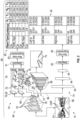
- a system for predicting lane lines and lane types through neural networks is shown and indicated generally by reference number 10.
- the system 10 operates on a vehicle 12.
- the vehicle 12 is illustrated as a passenger vehicle, however the vehicle 12 may be a truck, sport utility vehicle, van, motor home, or any other type of road vehicle, water vehicle, or air vehicle without departing from the scope or intent of the present disclosure.
- the vehicle 12 is equipped with one or more of a throttle system 14, a braking system 16, a transmission system 18, and a steering system 20.
- a vehicle operator uses the throttle system 14 to control a rate of acceleration of the vehicle 12.
- the throttle system 14 controls a torque output of propulsion devices 22 that motivate the vehicle 12.
- the propulsion devices 22 may take any of a variety of different forms, depending on the vehicle 12 type.
- the propulsion devices 22 may include electric motors or motivators, internal combustion engines, pneumatic or hydraulic motivators, or any other sort of prime mover.
- the braking system 16 controls a rate of deceleration of the vehicle 12.
- the braking system 16 may operate or control a quantity of braking pressure applied to the disc or drum brakes 24 of an exemplary vehicle 12.
- the transmission system 18 controls directional movement of the vehicle 12.
- the transmission may be a geared transmission such as a manual transmission, a dual clutch transmission, a continuously variable transmission, an automatic transmission, any combination of these transmission types, or the like.
- the transmission system 18 may control a direction of rotation of electric motors or motivators disposed in and providing propulsion to the vehicle 12.
- the steering system 20 controls a yaw rate of the vehicle 12 and may include steerable wheels 26, in combination with a steering apparatus such as a steering wheel 28, a tiller or any of a variety of hydrodynamic control surfaces providing yaw control to a watercraft, or any of a variety of aeronautical control surfaces providing yaw control to an aircraft.
- a steering apparatus such as a steering wheel 28, a tiller or any of a variety of hydrodynamic control surfaces providing yaw control to a watercraft, or any of a variety of aeronautical control surfaces providing yaw control to an aircraft.
- the vehicle 12 is equipped with one or more control modules 30.
- Each control module 30 is a non-generalized electronic control device having a preprogrammed digital computer or processor 32, memory or non-transitory computer readable medium 34 used to store data such as control logic, instructions, image data, lookup tables, and the like, and a plurality of input/output (I/O) peripherals or ports 36.
- the processor 32 is configured to execute the control logic or instructions.
- the control logic or instructions include any type of computer executable program code, including source code, object code, and executable code.
- the control logic also includes software programs configured to perform a specific function or set of functions.
- the control logic may include one or more computer programs, software components, sets of instructions, procedures, functions, objects, classes, instances, related data, or a portion thereof adapted for implementation in a suitable computer readable program code.
- the control logic may be stored within the memory 34 or in additional or separate memory.
- the control modules 30 may have additional processors 32 or additional integrated circuits in communication with the processors 32, such as perception logic circuits for analyzing visual data, or dedicated vehicle-to-vehicle (V2V) or vehicle-to-infrastructure (V2I) circuits. Alternatively, the functions of the control module 30 may be distributed across a variety of sub-systems.
- the memory 34 includes media where data can be permanently stored and/or media where data can be stored and later overwritten, such as a rewritable optical disc or erasable memory device. In further examples, the memory 34 may include any of a variety of different storage media, such as flash memory, an embedded multimedia card (EMMC) flash memory, a random access memory (RAM), or the like.
- the I/O ports 36 receive input data from one or more sensors 38 and actuators 40 of the vehicle 12.
- the sensors 38 include an optical sensing system 42 having sensors such as cameras 44, ultrasonic sensors, light detection and ranging (LiDAR) units 46, and radio detection and ranging (RADAR) units 48.
- the sensors 38 of the optical sensing system 42 are shown in four distinct locations in FIG. 1 , however, it should be appreciated that the sensors 38 may be located at any of a variety of other locations on or off the vehicle 12.
- the sensors 38 also include movement sensors such as gyroscopic sensors 50, accelerometers 52, and the like.
- the actuators 40 should be understood to include any of a variety of electronic, hydraulic, and pneumatic devices capable of altering the movement of the vehicle 12.
- the actuators 40 include a throttle actuator 54 of the throttle system 14 operable to alter a quantity of torque generated by the propulsion device 22 of the vehicle 12.
- the actuators 40 include a brake actuator 56 of the braking system 16.
- the brake actuator 56 is operable to alter a quantity of deceleration applied by the braking system 16 of the vehicle 12.
- the actuators 40 include a transmission ratio selector 58 of the transmission system 18, and a steering actuator 60 of the steering system 20.
- the transmission ratio selector 58 is operable to alter a direction and/or rate of motion of the vehicle 12.
- the steering actuator 60 adjusts a yaw rate of the vehicle 12.
- the control module 30 communicates electronically, pneumatically, hydraulically, or the like, with a variety of on-board systems, such as the throttle system 14, the braking system 16, the transmission system 18, and the steering system 20.
- the control module 30 of the system 10 collects and analyzes optical information collected by the vehicle 12 about the vehicle's 12 surroundings.
- the system 10 collects or captures optical information in the form of an input image 61 from one or more optical sensors 38 such as cameras 44.
- the cameras 44 are disposed on a host member such as the vehicle 12.
- the system 10 then utilizes a heterogeneous convolutional neural network (HCNN) 66 to analyze the optical information and to train itself to recognize features within the optical information in the input image 61.
- the HCNN 66 is a computer executable program code or software stored in the memory 34 and executed by the processor 32 of the control module 30.
- the HCNN 66 includes a feature extraction layer (FEL) portion 68 as well as at least three distinct sub-networks, each performing a different task.
- the three distinct sub-networks include: a first sub-network 70, a second sub-network 72, and a third sub-network 74 which will be described in further detail below.
- the FEL portion 68 captures objects in the input image 61 and then in each of the first, second and third sub-networks 70, 72, 74 predicts the objects, lane lines 75, and lane line types in the input image 61.
- the FEL portion 68 includes multiple convolution and activation layers 76, stacked together with pooling layers 78. Each convolution and activation layer 76 is stacked together with a pooling layer 78.
- the FEL portion 68 receives the input image 61 directly from the cameras 44 on the host member or vehicle 12.
- the FEL portion 68 carries out a plurality of operations to refine the input image 61 into usable data.
- the FEL portion 68 conducts a learning operation to learn to represent at least a first stage of data 69 of the input image 61 in a form including horizontal and vertical lines, as well as simple blobs of color.
- the horizontal and vertical lines represent horizontal and vertical components of objects or road markings in the input image 61.
- the output of the first stage of data 69 defines the coordinates of objects, lane lines 75, and the like in the input image 61.
- columns X1, Y1, X2, and Y2 define top left, top right, bottom left and bottom right coordinates, respectively of the objects or road markings in the input image 61. That is, X1 defines a position of the top left coordinate of an object, road marking, or the like.
- Y1 defines a position of the top right coordinate of each object, road marking, or the like.
- X2 and Y2 define the bottom left and bottom right coordinates of each object, road marking, or the like in the input image 61.
- the simple blobs of color are defined by clusters of dots which approximate the size and shape of objects within the input image 61 received by the FEL portion 68.
- the FEL portion 68 outputs the first stage of data 69 to at least the first sub-network, the second sub-network, and the third sub-network.
- the first sub-network 70 directly receives the first stage of data 69 from the FEL portion 68 and analyzes the first stage of data 69 to create a detected object table 80.
- the first sub-network 70 analyzes the first stage of data 69 to perform object detection, object classification, and object localization for classes of objects within the input image 61.
- the first stage of data 69 is received by a first convolution and pooling (CPL) portion 82 of the FEL 68.
- the first CPL portion 82 captures or detects 81 shapes including at least circles, rectangles, and triangles within the input image 61, which are then used to create the detected object table 80.
- the shapes detected 81 in the input image 61 are then extracted.
- a confidence level or value is assigned to each object detected within the input image 61. Specifically, non-maximum values or confidence levels are suppressed 83 so that a maximum value or maximum confidence value is extracted for each object detected within the input image 61.
- the first stage of data 69 is capable of capturing small objects, i.e. objects smaller than a human, a pet, or the like, in the input image 61. It should be appreciated that while specific shapes have been listed above, these shapes are non-limiting. Any of a variety of different shapes may be detected without departing from the scope or intent of the present disclosure.
- the results of the object detection, classification, and localization analysis are outputted as a second stage of data 83.
- the second stage of data 83 is forwarded to the first sub-network 70 to generate the detected object table and stored in memory 34.
- the exemplary detected object table 80 several types of objects are indicated in the left-most column, including: car, traffic sign, and the like. It should be appreciated that the detected object table 80 may include any of a variety of detected objects including those listed, as well as pedestrians, other types of motor vehicles, trees, railings and/or fences, bollards, road hazards, and the like.
- a second CPL portion 84 of the FEL portion 68 captures a third stage of data 85.
- the third stage of data 85 defines complex geometries within the input images 61.
- the complex geometries are formed of combinations of the first stage of data 69 and the second stage of data 83. Additionally, the complex geometries define complex features or feature combinations detected within the input image 61.
- the complex features are: wheels, faces, and grids, or the like.
- the wheels are automobile, motorcycle, or bicycle wheels, the faces are curbs, signs, and the like, or human faces, or animal silhouettes.
- the third stage of data 85 is then forwarded from the second CPL portion 84 to the first sub-network 70 where the first sub-network utilizes the third stage of data 85 to perform object detection, classification, and localization and augment the detected object table.
- the second CPL portion 84 forwards the third stage of data 85 to the second sub-network 72 for performing the task of lane line 75 detection and localization and to create a lane line location table 87.
- the second CPL portion 84 receives the first and the second stages of data 69, 83.
- the second stage of data 83 captures shapes including at least lines, circles, rectangles, and triangles.
- the second stage of data 83 is forwarded to the second sub-network 72.
- the second-sub-network 72 passes the first and second stages of data 69, 83 through a series of up-sampling layers 88 and deconvolution layers 90. Each up-sampling layer 88 is paired with at least one deconvolution layer 90.
- the second sub-network 72 performs the task of lane line 75 detection and localization for classes of lane lines 75 in the input image 61.
- the lane line 75 detection and localization for classes of lane lines 75 are used to generate the lane line location table 87.
- a third CPL portion 86 within the FEL portion 68 receives the first stage of data 69 and the second stage of data 83, including at least lines, circles, rectangles, and triangles.
- the third CPL portion 86 forwards the second stage of data 83 to the third sub-network 74 to perform the task of lane line 75 type detection for classes of lane line 75 types in the input image 61, and to create a detected lane line type table 92. More specifically, the third CPL portion 86 passes the third stage of data 85 through at least three fully connected layers 94 of the HCNN 66, in which the third CPL portion 86 defines complex geometries including combinations of the first and second stages of data 69, 83 and complex feature combinations.
- the complex feature combinations form representations of lane lines 75 and the like. Additionally, the second CPL portion 84 forwards the third stage of data 85 from to the third sub-network 74 to perform the task of lane line 75 type detection for classes of lane line 75 types in the input image 61, and to create the detected lane line type table 92.
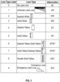
- the detected lane line type table 92 is generated by an algorithm or computer executable program code stored within the memory 34 and executed by the processor 32 that predicts at least ten values for each lane line 75 detected within the input image 61.
- a confidence level or value is assigned to each of the ten values for each lane line 75 within the input image 61.
- the values for each lane line 75 detected 93 in the input image 61 are then extracted. Specifically, non-maximum values or confidence levels are suppressed 95 so that a maximum value or maximum confidence value is extracted for each lane line 75 detected within the input image 61.
- Each of the ten values corresponds to a particular lane line 75 type.
- a zero (0) value corresponds to a nonexistent lane line (NL).
- An unknown (Unk) lane line corresponds to a one (1) value.
- a dashed white line (DW) corresponds to a two (2) value.
- a solid white line (SW) corresponds to a three (3) value.
- a Dashed yellow line (DY) corresponds to a four (4) value.
- a solid yellow line (SY) corresponds to a five (5) value.
- a dashed yellow solid yellow line (DYSY) corresponds to a six (6) value.
- a solid yellow dashed yellow line (SYDY) corresponds to a seven (7) value.
- a double solid yellow line (DSY) corresponds to an eight (8) value, and an emergency lane line (Eml) corresponds to a nine (9) value.
- the maximum value extracted for each lane line 75 detected in the input image 61 is then outputted or extracted to the detected lane line type table 92.
- the first sub-network 70 is further trained by minimizing a loss function of the first subnetwork 70 while freezing the second sub-network 72 and the third sub-network 74.
- the second sub-network 72 is trained by minimizing a loss function of the second sub-network 72 while freezing the first and the third sub-networks 70, 74.
- the third sub-network 74 is trained by minimizing a loss function of the third subnetwork 74 while freezing the first and second sub-networks 70, 72.
- the term "minimizing" means decreasing as close to zero as possible.
- minimizing the loss functions is intended to impart the concept that the loss functions are decreased as close to zero so that the loss functions have as small an effect on the sub-networks 70, 72, 74 as possible during training of each of the sub-networks 70, 72, 74.
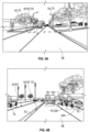
- FIG. 4A depicts an overlay of system 10 outputs on a daytime image of a road surface 96 including lane lines 75 (Uk, SYSY, Uk, NL), and objects [e.g. a pedestrian (Ped), several cars (car), and trees (Ts)] within the field of view of the sensors 38 equipped to an exemplary vehicle 12.
- FIG. 4A depicts an overlay of system 10 outputs on a daytime image of a road surface 96 including lane lines 75 (Uk, SYSY, Uk, NL), and objects [e.g. a pedestrian (Ped), several cars (car), and trees (Ts)] within the field of view of the sensors 38 equipped to an exemplary vehicle 12.
- lane lines 75 Uk, SYSY, Uk, NL
- objects e.g. a pedestrian (Ped), several cars (car), and trees (Ts)
- the HCNN 66 predicts object locations in the input image 61 with the first sub-network 70, predicts lane line 75 locations in the input image 61 with the second sub-network 72, and predicts lane line 75 types for each predicted lane line 75 in the input image 61 with the third sub-network 74.
- the method 200 begins at block 202.
- one or more optical sensors 38 disposed on a host member or vehicle 12 captures an input image 61.
- the input image 61 is passed to the three distinct sub-networks 70, 72, 74, respectively, of the HCNN 66.
- the input image 61 is passed to the first sub-network 70, where the input image 61 is received in the FEL portion 68 of the HCNN 66.
- the FEL portion 68 conducts a learning operation to represent at least a first stage of data 69 in the input image 61 in a form including horizontal and vertical lines, and simple blobs of color.
- the FEL portion 68 outputs the first stage of data 69 to the first, second, and third sub-networks 70, 72, 74.
- the first stage of data 69 is received directly from the FEL portion 68 by the first sub-network 70.
- the first sub-network 70 performs the first task of object detection, classification, and localization for classes of objects in the input image 61. More specifically, at block 21 0A, the first sub-network 70 receives the first stage of data 69 within the first CPL portion 82 of the FEL portion 68.
- the first CPL portion 82 captures a second stage of data including shapes such as circles, rectangles, and triangles.
- the second stage of data is forwarded to the first sub-network 70.
- the first sub-network 70 performs the first task of object detection, classification, and localization for classes of objects found in the input image 61 and creates the detected object table.
- a third stage of data 85 is captured within a second CPL portion 84.
- the third stage of data 85 defines complex geometries found in the input image 61.
- the complex geometries include combinations of the first stage of data 69 and the second stage of data, as well as complex feature combinations that form a representation of wheels, faces, and grids within the input image 61.
- the second CPL portion 84 forwards the third stage of data 85 to the first sub-network 70 for performing the first task of object detection, classification, and localization for classes of objects in the input image 61.
- the third stage of data 85 augments and refines the detected object table.
- the first stage of data 69 is received directly within the second CPL portion 84 of the FEL portion 68.
- the second sub-network 72 performs the second task of lane line 75 detection and creates the lane line location table. More specifically, at block 212B, the second CPL portion 84 receives the second stage of data capturing shapes including at least: lines, circles, rectangles, and triangles.
- the second CPL portion 84 forwards the second stage of data to the second sub-network 72 for performing the second task of lane line 75 detection and creates the lane line location table 87.
- the third stage of data 85 is captured within the second CPL portion 84.
- the third stage of data 85 defines complex geometries including: combinations of the first and second stages of data, and complex feature combinations that are used to form a representation including lane lines 75.
- the second CPL portion 84 forwards the third stage of data 85 directly to the second sub-network 72, and at block 220B the second sub-network 72 performs the second task of lane line 75 detection and localization for classes of lane lines 75 in the input image 61, and to create the lane line location table 87.
- the first stage of data 69 is received directly from the FEL portion 68 by the third sub-network 74.
- the third sub-network 74 performs the third task of lane line 75 type detection to create the lane line type table 92.
- the third CPL portion 86 captures the third stage of data 85.
- the third stage of data 85 defines complex geometries including: combinations of the first and second stages of data, and complex feature combinations that are used to form a representation including lane lines 75.
- the second CPL portion 84 forwards the third stage of data 85 to the third sub-network 74 where, at block 212C the third sub-network 74 performs the third task of lane line 75 type detection for classes of lane lines 75 in the input image 61, and for creating the detected lane line type table 92.
- the third sub-network 74 predicts at least ten values for each lane line 75 in the input image 61.
- the third sub-network 74 extracts values for each lane line 75 in the input image 61.
- the third sub-network 74 extracts a maximum value for each lane line 75, and at block 220C, the third sub-network 74 extracts a lane line 75 label corresponding to the maximum value for each lane line 75 found in the input image 61.
- the method 200 takes the outputs of the detected object table 80 from block 220A, the lane line location table 87 from block 218B, and the lane line 75 labels in the detected lane line type table 92 from block 220C to train the first, second, and third sub-networks 70, 72, 74. More specifically, at block 222, the method 200 trains the first sub-network 70 by minimizing a loss function of the first sub-network 70 while freezing the second and third sub-networks 72, 74. Likewise, at block 224, the method 200 trains the second sub-network 72 by minimizing the loss function of the second sub-network 72 while freezing the first and third sub-networks 70, 74.
- the method 200 trains the third sub-network 74 by minimizing the loss function of the third sub-network 74 while freezing the first and second sub-networks 70, 72. While in the foregoing, steps 210A-220A, 210B-218B, and 210C-220C appear sequentially, it should be appreciated that the "A”, “B", and “C"-labeled steps may be performed concurrently or sequentially without departing from the scope or intent of the present disclosure. That is Steps 210B-218B may be performed before, after, or concurrently with steps 210A-220A and 210C-220C.
- steps 210C-220C may be performed before, after, or concurrently with steps 210B-218B and before, after, or concurrently with steps 210A-220A.
- steps 222-226 may be performed in the sequence described above, or the steps may be performed in any other order without departing from the scope or intent of the present disclosure.
- the method 200 ends, whereupon the method 200 returns to block 202 to begin again.
- the method 200 runs continuously and recursively while the vehicle 12 is operating, however the method 200 may also be used to train the HCNN 66 only, and may therefore in other examples only run intermittently.
- a system and method for predicting lane line 75 types with neural networks offers several advantages. These include the ability to utilize preexisting infrastructure to perform image analyses that overcome optical interference caused by weather, debris, and the like. Moreover, the system and method of the present disclosure can mimic and improve upon a human driver's ability to determine the positions and types of lane lines 75 on a road surface 96. The system and method further provide robust predictions of both lane lines 75 and lane types even when the road surface 96 is obscured by weather, debris, and the like.
Landscapes
- Engineering & Computer Science (AREA)
- Theoretical Computer Science (AREA)
- Physics & Mathematics (AREA)
- General Physics & Mathematics (AREA)
- Evolutionary Computation (AREA)
- General Health & Medical Sciences (AREA)
- Health & Medical Sciences (AREA)
- Artificial Intelligence (AREA)
- Software Systems (AREA)
- Computing Systems (AREA)
- Multimedia (AREA)
- Biomedical Technology (AREA)
- Data Mining & Analysis (AREA)
- General Engineering & Computer Science (AREA)
- Computational Linguistics (AREA)
- Mathematical Physics (AREA)
- Biophysics (AREA)
- Molecular Biology (AREA)
- Life Sciences & Earth Sciences (AREA)
- Computer Vision & Pattern Recognition (AREA)
- Databases & Information Systems (AREA)
- Medical Informatics (AREA)
- Mechanical Engineering (AREA)
- Image Analysis (AREA)
Claims (14)
- Verfahren zur Vorhersage von Spurlinienarten unter Verwendung eines heterogenen konvolutionalen neuronalen Netzwerks (HCNN), wobei das Verfahren umfasst:Erfassen eines Eingangsbildes mit einem oder mehreren optischen Sensoren, die auf einem Host-Element angeordnet sind;Durchlaufen des Eingangsbildes durch das HCNN, wobei das HCNN eine Merkmalsextraktionsschicht (feature extraction layer, FEL) und mindestens drei verschiedene Teilnetze umfasst, wobei die drei verschiedenen Teilnetze jeweils eine andere Aufgabe erfüllen:Vorhersagen von Objektpositionen im Eingangsbild mit einem ersten Teilnetz; Erkennen von Fahrspurlinien und Vorhersagen von Fahrspurlinienpositionen für Klassen von Fahrspurlinien im Eingangsbild, um die Fahrspurlinientabelle mit einem zweiten Teilnetz zu erstellen;und Vorhersagen von Fahrspurlinientypen für jede vorhergesagte Fahrspurlinie in dem Eingangsbild mit einem dritten Teilnetz;wobei ein Lernvorgang in dem FEL durchgeführt wird, um zu lernen, mindestens eine erste Stage von Daten des Eingangsbildes in einer Form darzustellen, die horizontale und vertikale Linien und einfache Farbkleckse enthält, unddie erste Stage von Daten in einem ersten Konvolutions- und Pooling- (CPL)-Teil des FEL empfangen wird und eine zweite Stage von Daten, die Formen wie Kreise, Rechtecke und Dreiecke enthält, von dem ersten CPL-Teil erfasst wird; unddie erste Stage von Daten und die zweite Stage von Daten in einem zweiten CPL-Abschnitt des FEL empfangen werden, und eine dritte Stage von Daten, die komplexe Geometrien einschließlich Kombinationen aus den ersten und zweiten Stagen von Daten und komplexe Merkmalskombinationen definiert, die verwendet werden, um eine Fahrspurlinien enthaltende Darstellung zu bilden, in einem zweiten CPL-Abschnitt des FEL erfasst wird; unddie dritte Stage von Daten wird von dem zweiten CPL-Teil an das zweite Teilnetz weitergeleitet, um eine Spurlinienerkennung und -lokalisierung für Klassen von Spurlinien in dem Eingangsbild durchzuführen, um die Spurlinienpositionstabelle zu erstellen.
- Verfahren nach Anspruch 1, wobei das Durchlaufen des Eingangsbildes durch das HCNN ferner umfasst:direktes Empfangen des Eingangsbildes im Teil der Merkmalsextraktionsschicht (FEL) des HCNN, wobei das HCNN mehrere Faltungsschichten, Poolingschichten und Aktivierungsschichten hat, die miteinander gestapelt sind;und Ausgeben der ersten Stage von Daten an mindestens: das erste Teilnetz, das zweite Teilnetz und das dritte Teilnetz;direktes Empfangen der ersten Stage von Daten aus dem FEL-Teil durch das erste Teilnetz und Ausführen einer ersten Aufgabe der Objekterkennung, -klassifizierung und -lokalisierung für Klassen von Objekten im Eingangsbild, um eine Tabelle der erkannten Objekte zu erstellen;direktes Empfangen der ersten Stage von Daten aus dem FEL-Teil durch das zweite Teilnetz und Ausführen einer zweiten Aufgabe der Spurlinienerkennung, um eine Spurlinienpositionstabelle zu erstellen; unddirektes Empfangen der ersten Stage von Daten aus dem FEL-Teil durch das dritte Teilnetz und Ausführen einer dritten Aufgabe zur Erkennung des Fahrspurtyps, um eine Fahrspurtyp-Tabelle zu erstellen.
- Verfahren nach Anspruch 2 ferner umfassend:Empfangen der ersten Stage von Daten innerhalb des ersten Faltungs- und Pooling-Teils (CPL) des FEL;Empfangen einer zweiten Stage von Daten, die Formen einschließlich zumindest Kreise, Rechtecke und Dreiecke erfasst; undWeiterleiten der zweiten Stage von Daten an das erste Teilnetz zur Durchführung der ersten Aufgabe der Objekterkennung, -klassifizierung und -lokalisierung für Klassen von Objekten im Eingangsbild, um die Tabelle der erkannten Objekte zu erstellen.
- Verfahren nach Anspruch 3 ferner umfassend:
Weiterleiten der dritten Stage von Daten aus dem zweiten CPL-Teil an das erste Teilnetz zur Durchführung der ersten Aufgabe der Objekterkennung, - klassifizierung und -lokalisierung für Klassen von Objekten im Eingangsbild, um die Tabelle der erkannten Objekte zu erweitern, wobei die dritte Stage von Daten komplexe Geometrien definiert, die Kombinationen der ersten Stage von Daten und der zweiten Stage von Daten und komplexe Merkmalskombinationen enthalten, um eine Darstellung zu bilden, die Räder, Flächen und Gitter enthält. - Verfahren nach Anspruch 4 ferner umfassend:Empfangen der zweiten Stage der Datenerfassung von Formen, die mindestens Linien, Kreise, Rechtecke und Dreiecke umfassen; undWeiterleiten der zweiten Stage von Daten an das zweite Teilnetz zur Durchführung der zweiten Aufgabe der Fahrspurerkennung und -lokalisierung für Klassen von Fahrspurlinien im Eingangsbild, um die Fahrspurpositionstabelle zu erstellen.
- Verfahren nach Anspruch 4 ferner umfassend:Empfang der ersten Stage von Daten innerhalb eines dritten CPL-Abschnitts des FEL;Empfangen der zweiten Stage der Datenerfassung von Formen, die mindestens Linien, Kreise, Rechtecke und Dreiecke umfassen; undWeiterleiten der zweiten Stage von Daten an ein drittes Teilnetz zur Durchführung der dritten Aufgabe der Fahrspurlinien-Typ-Erkennung für Klassen von Fahrspurlinien-Typen im Eingangsbild, um eine Tabelle der erkannten Fahrspurlinien-Typen zu erstellen.
- Verfahren nach Anspruch 6 ferner umfassend:Erfassen der dritten Stage von Daten innerhalb des dritten CPL-Abschnitts, wobei die dritte Stage von Daten komplexe Geometrien definiert, die Kombinationen der ersten Stage von Daten und der zweiten Stage von Daten und komplexe Merkmalskombinationen enthalten, um eine Darstellung zu bilden, die Fahrspurlinien enthält; undWeiterleiten der dritten Stage von Daten von dem zweiten CPL-Teil an das dritte Teilnetz zum Durchführen der dritten Aufgabe der Spurlinientyp-Erkennung für Klassen von Spurlinientypen in dem Eingangsbild und Erzeugen einer Tabelle der erkannten Spurlinientypen, wobei das Erzeugen einer Tabelle der erkannten Spurlinientypen ferner umfasst:Vorhersagen von zehn Werten für jede Fahrspur im Eingabebild;Extrahieren von Werten für jede Fahrspur im Eingabebild;Extrahieren eines Maximalwerts für jede Fahrspurlinie; undExtrahieren einer dem Maximalwert entsprechenden Fahrspurbezeichnung.
- Verfahren nach Anspruch 1 ferner umfassend:Trainieren des ersten Teilnetzes durch Minimieren einer Verlustfunktion des ersten Teilnetzes bei gleichzeitigem Einfrieren des zweiten Teilnetzes und des dritten Teilnetzes;Trainieren des zweiten Teilnetzes durch Minimieren einer Verlustfunktion des zweiten Teilnetzes bei gleichzeitigem Einfrieren des ersten Teilnetzes und des dritten Teilnetzes; undTrainieren des dritten Teilnetzes durch Minimieren einer Verlustfunktion des dritten Teilnetzes bei gleichzeitigem Einfrieren des ersten Teilnetzes und des zweiten Teilnetzes.
- System zur Vorhersage von Fahrspurtypen unter Verwendung eines heterogenen konvolutionalen neuronalen Netzwerks (HCNN), wobei das System umfasst:einen oder mehrere optische Sensoren, die auf einem Host-Element angeordnet sind, wobei der eine oder die mehreren optischen Sensoren ein Eingangsbild erfassen; undein HCNN mit einer Merkmalsextraktionsschicht (FEL) und mindestens drei verschiedenen Teilnetzen, wobei die drei verschiedenen Teilnetze umfassen:ein erstes Teilnetz, das die Objektpositionen im Eingangsbild vorhersagt;ein zweites Teilnetz, das Fahrspurlinien erkennt und Fahrspurlinienpositionen für Klassen von Fahrspurlinien im Eingangsbild vorhersagt, um die Fahrspurlinientabelle zu erstellen; undein drittes Teilnetz, das für jede vorhergesagte Fahrspurlinie im Eingangsbild die Fahrspurlinienarten vorhersagt, undwobei das HCNN das Eingangsbild empfängt und das Eingangsbild durch die drei verschiedenen Teilnetze leitet,wobei ein Lernvorgang im FEL durchgeführt wird, um zu lernen, mindestens eine erste Stage von Daten des Eingangsbildes in einer Form darzustellen, die horizontale und vertikale Linien und einfache Farbkleckse enthält, unddie erste Stage von Daten in einem ersten Faltungs- und Pooling- (CPL)-Teil des FEL empfangen wird und eine zweite Stage von Daten, die Formen wie Kreise, Rechtecke und Dreiecke enthält, von dem ersten CPL-Teil erfasst wird; unddie erste Stage von Daten und die zweite Stage von Daten in einem zweiten CPL-Abschnitt des FEL empfangen werden und eine dritte Stage von Daten, die komplexe Geometrien definiert, die Kombinationen der ersten und zweiten Stagen von Daten und komplexe Merkmalskombinationen enthalten, die verwendet werden, um eine Darstellung zu bilden, die Fahrspurlinien enthält, in einem zweiten CPL-Abschnitt des FEL erfasst wird; unddie dritte Stage von Daten wird von dem zweiten CPL-Teil an das zweite Teilnetz weitergeleitet, um eine Spurlinienerkennung und -lokalisierung für Klassen von Spurlinien in dem Eingangsbild durchzuführen, um die Spurlinienpositionstabelle zu erstellen.
- System nach Anspruch 9, wenn das HCNN das Eingangsbild durch die drei verschiedenen Teilnetze leitet, wobei das Eingangsbild direkt im Merkmalsextraktionsschichtteil (FEL) des HCNN empfangen wird, wobei das HCNN mehrere Faltungsschichten, Pooling- und Aktivierungsschichten aufweist, die miteinander gestapelt sind;der FEL-Teil gibt die erste Stage von Daten an mindestens das erste Teilnetz, das zweite Teilnetz und das dritte Teilnetz aus;das erste Teilnetz empfängt direkt die Daten vom FEL-Teil und führt eine erste Aufgabe der Objekterkennung, -klassifizierung und -lokalisierung für Klassen von Objekten im Eingangsbild durch, um eine Tabelle der erkannten Objekte zu erstellen;das zweite Teilnetz empfängt direkt die Daten von dem FEL-Teil und führt eine zweite Aufgabe der Spurlinienerfassung durch, um eine Spurlinienpositionstabelle zu erstellen; unddas dritte Teilnetz empfängt direkt die Daten vom FEL-Teil und führt eine dritte Aufgabe der Fahrspurlinienart-Erkennung durch, um eine Fahrspurlinienart-Tabelle zu erstellen.
- System nach Anspruch 10, bei dem die erste Stage von Daten innerhalb des ersten Faltungs- und Pooling-Teils (CPL) des FEL empfangen wird;eine zweite Stage von Daten, die zumindest Kreise, Rechtecke und Dreiecke umfassende Formen umfasst, innerhalb eines ersten CPL-Abschnitts des FEL empfangen wird; unddie zweite Stage von Daten an das erste Teilnetz weitergeleitet wird, wobei das erste Teilnetz die erste Aufgabe der Objekterkennung, -klassifizierung und - lokalisierung für Klassen von Objekten in dem Eingangsbild durchführt, um die Tabelle der erkannten Objekte zu erstellen.
- System nach Anspruch 11, wobeider zweite CPL-Teil die dritte Stage von Daten an das erste Teilnetz weiterleitet, wobei das erste Teilnetz die erste Aufgabe der Objekterkennung, -klassifizierung und -lokalisierung für Klassen von Objekten in dem Eingangsbild durchführt, um die Tabelle der erkannten Objekte zu erweitern,wobei die erste Stage von Daten innerhalb des zweiten CPL-Abschnitts des FEL empfangen wird;die zweite Stage von Daten an das zweite Teilnetz weitergeleitet wird, wobei das zweite Teilnetz die zweite Aufgabe der Spurlinienerkennung und -lokalisierung für Klassen von Spurlinien in dem Eingangsbild durchführt, um die Spurlinienpositionstabelle zu erstellen,wobei die erste Stage von Daten innerhalb eines dritten CPL-Abschnitts des FEL empfangen wird;die zweite Stage von Daten innerhalb des dritten CPL-Abschnitts des FEL empfangen wird, wobei die zweite Stage von Daten zumindest Linien, Kreise, Rechtecke und Dreiecke umfassende Formen erfasst; unddie zweite Stage von Daten an ein drittes Teilnetz weitergeleitet wird, wobei das dritte Teilnetz die dritte Aufgabe der Fahrspurlinien-Typ-Erkennung für Klassen von Fahrspurlinien-Typen in dem Eingangsbild durchführt, um eine Tabelle der erkannten Fahrspurlinien-Typen zu erstellen.
- System nach Anspruch 12, bei dem die dritte Stage von Daten innerhalb des dritten CPL-Teils erfasst wird, wobei die dritte Stage von Daten komplexe Geometrien definiert, die Kombinationen der ersten Stage von Daten und der zweiten Stage von Daten und komplexe Merkmalskombinationen enthalten, um eine Darstellung zu bilden, die Fahrspurlinien enthält; und
die dritte Stage von Daten von dem dritten CPL-Teil an das dritte Teilnetz weitergeleitet wird, wobei das dritte Teilnetz die dritte Aufgabe der Fahrspurlinien-typ-Erkennung für Klassen von Fahrspurlinientypen in dem Eingangsbild durchführt und eine Tabelle der erkannten Fahrspurlinientypen erzeugt. - System nach Anspruch 13, wobei der dritte CPL-Teil eine Tabelle der erkannten Fahrspurlinienarten erstellt, durch:Vorhersagen von zehn Werten für jede Fahrspur im Eingabebild;Extrahieren von Werten für jede Fahrspur im Eingabebild;Extrahieren eines Maximalwerts für jede Fahrspurlinie;Extrahieren eines Spurlinienetiketts aus der Tabelle der erkannten Spurlinientypen, das dem Maximalwert entspricht;Trainieren des ersten Teilnetzes durch Minimieren einer Verlustfunktion des ersten Teilnetzes bei gleichzeitigem Einfrieren des zweiten Teilnetzes und des dritten Teilnetzes;Trainieren des zweiten Teilnetzes durch Minimieren einer Verlustfunktion des zweiten Teilnetzes bei gleichzeitigem Einfrieren des ersten Teilnetzes und des dritten Teilnetzes; undTrainieren des dritten Teilnetzes durch Minimieren einer Verlustfunktion des dritten Teilnetzes bei gleichzeitigem Einfrieren des ersten Teilnetzes und des zweiten Teilnetzes.
Applications Claiming Priority (1)
| Application Number | Priority Date | Filing Date | Title |
|---|---|---|---|
| US17/245,038 US11887381B2 (en) | 2021-04-30 | 2021-04-30 | Use of HCNN to predict lane lines types |
Publications (3)
| Publication Number | Publication Date |
|---|---|
| EP4083941A1 EP4083941A1 (de) | 2022-11-02 |
| EP4083941C0 EP4083941C0 (de) | 2024-08-07 |
| EP4083941B1 true EP4083941B1 (de) | 2024-08-07 |
Family
ID=81389194
Family Applications (1)
| Application Number | Title | Priority Date | Filing Date |
|---|---|---|---|
| EP22170297.0A Active EP4083941B1 (de) | 2021-04-30 | 2022-04-27 | Verwendung von hcnn zur vorhersage von spurlinienarten |
Country Status (3)
| Country | Link |
|---|---|
| US (1) | US11887381B2 (de) |
| EP (1) | EP4083941B1 (de) |
| CN (1) | CN115272996A (de) |
Families Citing this family (1)
| Publication number | Priority date | Publication date | Assignee | Title |
|---|---|---|---|---|
| US12405116B2 (en) * | 2023-03-03 | 2025-09-02 | Telenav, Inc. | Navigation system with automatic optical calibration mechanism and method of operation thereof |
Family Cites Families (12)
| Publication number | Priority date | Publication date | Assignee | Title |
|---|---|---|---|---|
| US9286524B1 (en) * | 2015-04-15 | 2016-03-15 | Toyota Motor Engineering & Manufacturing North America, Inc. | Multi-task deep convolutional neural networks for efficient and robust traffic lane detection |
| US9902401B2 (en) * | 2015-05-10 | 2018-02-27 | Mobileye Vision Technologies Ltd. | Road profile along a predicted path |
| US20170076195A1 (en) * | 2015-09-10 | 2017-03-16 | Intel Corporation | Distributed neural networks for scalable real-time analytics |
| US9829888B2 (en) * | 2015-11-17 | 2017-11-28 | Ford Global Technologies, Llc | Distinguishing lane markings for a vehicle to follow |
| US10032067B2 (en) * | 2016-05-28 | 2018-07-24 | Samsung Electronics Co., Ltd. | System and method for a unified architecture multi-task deep learning machine for object recognition |
| EP3532801B1 (de) * | 2016-10-31 | 2020-12-16 | Mobileye Vision Technologies Ltd. | Systeme und verfahren zur navigation von spurzusammenführungen und spurtrennungen |
| US10402995B2 (en) * | 2017-07-27 | 2019-09-03 | Here Global B.V. | Method, apparatus, and system for real-time object detection using a cursor recurrent neural network |
| US20190147255A1 (en) * | 2017-11-15 | 2019-05-16 | Uber Technologies, Inc. | Systems and Methods for Generating Sparse Geographic Data for Autonomous Vehicles |
| US10803325B2 (en) * | 2017-11-15 | 2020-10-13 | Uatc, Llc | Autonomous vehicle lane boundary detection systems and methods |
| US11080537B2 (en) * | 2017-11-15 | 2021-08-03 | Uatc, Llc | Autonomous vehicle lane boundary detection systems and methods |
| EP3537348A1 (de) * | 2018-03-06 | 2019-09-11 | Dura Operating, LLC | Heterogenes neuronales faltungsnetzwerk zur lösung mehrerer probleme |
| CN110414387B (zh) * | 2019-07-12 | 2021-10-15 | 武汉理工大学 | 一种基于道路分割的车道线多任务学习检测方法 |
-
2021
- 2021-04-30 US US17/245,038 patent/US11887381B2/en active Active
-
2022
- 2022-04-27 CN CN202210452279.1A patent/CN115272996A/zh active Pending
- 2022-04-27 EP EP22170297.0A patent/EP4083941B1/de active Active
Also Published As
| Publication number | Publication date |
|---|---|
| EP4083941C0 (de) | 2024-08-07 |
| US11887381B2 (en) | 2024-01-30 |
| EP4083941A1 (de) | 2022-11-02 |
| US20220350992A1 (en) | 2022-11-03 |
| CN115272996A (zh) | 2022-11-01 |
Similar Documents
| Publication | Publication Date | Title |
|---|---|---|
| US11120691B2 (en) | Systems and methods for providing warnings to surrounding vehicles to avoid collisions | |
| US10345822B1 (en) | Cognitive mapping for vehicles | |
| JP6970807B2 (ja) | 移動体制御装置 | |
| US10489686B2 (en) | Object detection for an autonomous vehicle | |
| EP3795457B1 (de) | Vorbereitung von autonomen fahrzeugen für die kurvenfahrt | |
| CN109117709A (zh) | 用于自动驾驶车辆的碰撞避免系统 | |
| EP4083940A1 (de) | Verwendung von neuronalen netzen zum vorhersagen von fahrspurtypen | |
| US12039861B2 (en) | Systems and methods for analyzing the in-lane driving behavior of a road agent external to a vehicle | |
| CN110015293B (zh) | 限界区域和运动路径的低维度求取 | |
| JP2019151207A (ja) | 車両制御装置、車両制御方法、およびプログラム | |
| US20250298144A1 (en) | Methods for predicting behavior of an object with respect to operations of an autonomous vehicle based on lidar data | |
| US10546202B2 (en) | Proving hypotheses for a vehicle using optimal experiment design | |
| JP2019131077A (ja) | 車両制御装置、車両制御方法、およびプログラム | |
| CN117302215A (zh) | 用于执行最小危险操纵的车辆和操作该车辆的方法 | |
| Kemsaram et al. | An integrated framework for autonomous driving: Object detection, lane detection, and free space detection | |
| JP2019185112A (ja) | 車両制御装置、車両制御方法、およびプログラム | |
| US20240109559A1 (en) | Method and Control Device for the Situation-Dependent Determination of Observation Areas for Motor Vehicles Operated in an at Least Partially Autonomous Manner | |
| EP4113377A1 (de) | Verwendung von dbscan zur spurdetektion | |
| EP4083941B1 (de) | Verwendung von hcnn zur vorhersage von spurlinienarten | |
| US12227204B2 (en) | Systems and methods for detecting roadway lane boundaries | |
| JP2019185113A (ja) | 車両制御装置、車両制御方法、およびプログラム | |
| US11780471B1 (en) | System for determining a state of an object using thermal data | |
| US20220297673A1 (en) | Surround view localization of a vehicle | |
| US12046050B2 (en) | Systems and methods for detecting traffic lights using hierarchical modeling | |
| US20220297674A1 (en) | Surround view localization of a vehicle |
Legal Events
| Date | Code | Title | Description |
|---|---|---|---|
| PUAI | Public reference made under article 153(3) epc to a published international application that has entered the european phase |
Free format text: ORIGINAL CODE: 0009012 |
|
| STAA | Information on the status of an ep patent application or granted ep patent |
Free format text: STATUS: THE APPLICATION HAS BEEN PUBLISHED |
|
| AK | Designated contracting states |
Kind code of ref document: A1 Designated state(s): AL AT BE BG CH CY CZ DE DK EE ES FI FR GB GR HR HU IE IS IT LI LT LU LV MC MK MT NL NO PL PT RO RS SE SI SK SM TR |
|
| RAP1 | Party data changed (applicant data changed or rights of an application transferred) |
Owner name: NEW EAGLE LLC |
|
| STAA | Information on the status of an ep patent application or granted ep patent |
Free format text: STATUS: REQUEST FOR EXAMINATION WAS MADE |
|
| 17P | Request for examination filed |
Effective date: 20230428 |
|
| RBV | Designated contracting states (corrected) |
Designated state(s): AL AT BE BG CH CY CZ DE DK EE ES FI FR GB GR HR HU IE IS IT LI LT LU LV MC MK MT NL NO PL PT RO RS SE SI SK SM TR |
|
| GRAP | Despatch of communication of intention to grant a patent |
Free format text: ORIGINAL CODE: EPIDOSNIGR1 |
|
| STAA | Information on the status of an ep patent application or granted ep patent |
Free format text: STATUS: GRANT OF PATENT IS INTENDED |
|
| RIC1 | Information provided on ipc code assigned before grant |
Ipc: G06V 20/56 20220101ALI20240118BHEP Ipc: G06V 10/82 20220101AFI20240118BHEP |
|
| INTG | Intention to grant announced |
Effective date: 20240209 |
|
| GRAS | Grant fee paid |
Free format text: ORIGINAL CODE: EPIDOSNIGR3 |
|
| GRAA | (expected) grant |
Free format text: ORIGINAL CODE: 0009210 |
|
| STAA | Information on the status of an ep patent application or granted ep patent |
Free format text: STATUS: THE PATENT HAS BEEN GRANTED |
|
| AK | Designated contracting states |
Kind code of ref document: B1 Designated state(s): AL AT BE BG CH CY CZ DE DK EE ES FI FR GB GR HR HU IE IS IT LI LT LU LV MC MK MT NL NO PL PT RO RS SE SI SK SM TR |
|
| REG | Reference to a national code |
Ref country code: GB Ref legal event code: FG4D |
|
| REG | Reference to a national code |
Ref country code: CH Ref legal event code: EP |
|
| REG | Reference to a national code |
Ref country code: IE Ref legal event code: FG4D |
|
| REG | Reference to a national code |
Ref country code: DE Ref legal event code: R096 Ref document number: 602022005079 Country of ref document: DE |
|
| U01 | Request for unitary effect filed |
Effective date: 20240829 |
|
| U07 | Unitary effect registered |
Designated state(s): AT BE BG DE DK EE FI FR IT LT LU LV MT NL PT RO SE SI Effective date: 20240910 |
|
| PG25 | Lapsed in a contracting state [announced via postgrant information from national office to epo] |
Ref country code: NO Free format text: LAPSE BECAUSE OF FAILURE TO SUBMIT A TRANSLATION OF THE DESCRIPTION OR TO PAY THE FEE WITHIN THE PRESCRIBED TIME-LIMIT Effective date: 20241107 |
|
| PG25 | Lapsed in a contracting state [announced via postgrant information from national office to epo] |
Ref country code: PL Free format text: LAPSE BECAUSE OF FAILURE TO SUBMIT A TRANSLATION OF THE DESCRIPTION OR TO PAY THE FEE WITHIN THE PRESCRIBED TIME-LIMIT Effective date: 20240807 Ref country code: GR Free format text: LAPSE BECAUSE OF FAILURE TO SUBMIT A TRANSLATION OF THE DESCRIPTION OR TO PAY THE FEE WITHIN THE PRESCRIBED TIME-LIMIT Effective date: 20241108 |
|
| PG25 | Lapsed in a contracting state [announced via postgrant information from national office to epo] |
Ref country code: IS Free format text: LAPSE BECAUSE OF FAILURE TO SUBMIT A TRANSLATION OF THE DESCRIPTION OR TO PAY THE FEE WITHIN THE PRESCRIBED TIME-LIMIT Effective date: 20241207 |
|
| PG25 | Lapsed in a contracting state [announced via postgrant information from national office to epo] |
Ref country code: HR Free format text: LAPSE BECAUSE OF FAILURE TO SUBMIT A TRANSLATION OF THE DESCRIPTION OR TO PAY THE FEE WITHIN THE PRESCRIBED TIME-LIMIT Effective date: 20240807 |
|
| PG25 | Lapsed in a contracting state [announced via postgrant information from national office to epo] |
Ref country code: RS Free format text: LAPSE BECAUSE OF FAILURE TO SUBMIT A TRANSLATION OF THE DESCRIPTION OR TO PAY THE FEE WITHIN THE PRESCRIBED TIME-LIMIT Effective date: 20241107 Ref country code: ES Free format text: LAPSE BECAUSE OF FAILURE TO SUBMIT A TRANSLATION OF THE DESCRIPTION OR TO PAY THE FEE WITHIN THE PRESCRIBED TIME-LIMIT Effective date: 20240807 |
|
| PG25 | Lapsed in a contracting state [announced via postgrant information from national office to epo] |
Ref country code: RS Free format text: LAPSE BECAUSE OF FAILURE TO SUBMIT A TRANSLATION OF THE DESCRIPTION OR TO PAY THE FEE WITHIN THE PRESCRIBED TIME-LIMIT Effective date: 20241107 Ref country code: PL Free format text: LAPSE BECAUSE OF FAILURE TO SUBMIT A TRANSLATION OF THE DESCRIPTION OR TO PAY THE FEE WITHIN THE PRESCRIBED TIME-LIMIT Effective date: 20240807 Ref country code: NO Free format text: LAPSE BECAUSE OF FAILURE TO SUBMIT A TRANSLATION OF THE DESCRIPTION OR TO PAY THE FEE WITHIN THE PRESCRIBED TIME-LIMIT Effective date: 20241107 Ref country code: IS Free format text: LAPSE BECAUSE OF FAILURE TO SUBMIT A TRANSLATION OF THE DESCRIPTION OR TO PAY THE FEE WITHIN THE PRESCRIBED TIME-LIMIT Effective date: 20241207 Ref country code: HR Free format text: LAPSE BECAUSE OF FAILURE TO SUBMIT A TRANSLATION OF THE DESCRIPTION OR TO PAY THE FEE WITHIN THE PRESCRIBED TIME-LIMIT Effective date: 20240807 Ref country code: GR Free format text: LAPSE BECAUSE OF FAILURE TO SUBMIT A TRANSLATION OF THE DESCRIPTION OR TO PAY THE FEE WITHIN THE PRESCRIBED TIME-LIMIT Effective date: 20241108 Ref country code: ES Free format text: LAPSE BECAUSE OF FAILURE TO SUBMIT A TRANSLATION OF THE DESCRIPTION OR TO PAY THE FEE WITHIN THE PRESCRIBED TIME-LIMIT Effective date: 20240807 |
|
| PG25 | Lapsed in a contracting state [announced via postgrant information from national office to epo] |
Ref country code: SM Free format text: LAPSE BECAUSE OF FAILURE TO SUBMIT A TRANSLATION OF THE DESCRIPTION OR TO PAY THE FEE WITHIN THE PRESCRIBED TIME-LIMIT Effective date: 20240807 |
|
| PG25 | Lapsed in a contracting state [announced via postgrant information from national office to epo] |
Ref country code: CZ Free format text: LAPSE BECAUSE OF FAILURE TO SUBMIT A TRANSLATION OF THE DESCRIPTION OR TO PAY THE FEE WITHIN THE PRESCRIBED TIME-LIMIT Effective date: 20240807 |
|
| PG25 | Lapsed in a contracting state [announced via postgrant information from national office to epo] |
Ref country code: SK Free format text: LAPSE BECAUSE OF FAILURE TO SUBMIT A TRANSLATION OF THE DESCRIPTION OR TO PAY THE FEE WITHIN THE PRESCRIBED TIME-LIMIT Effective date: 20240807 |
|
| PLBE | No opposition filed within time limit |
Free format text: ORIGINAL CODE: 0009261 |
|
| STAA | Information on the status of an ep patent application or granted ep patent |
Free format text: STATUS: NO OPPOSITION FILED WITHIN TIME LIMIT |
|
| 26N | No opposition filed |
Effective date: 20250508 |
|
| REG | Reference to a national code |
Ref country code: CH Ref legal event code: H13 Free format text: ST27 STATUS EVENT CODE: U-0-0-H10-H13 (AS PROVIDED BY THE NATIONAL OFFICE) Effective date: 20251125 |
|
| U90 | Renewal fees not paid: noting of loss of rights |
Free format text: RENEWAL FEE NOT PAID FOR YEAR 04 Effective date: 20251117 |
|
| PG25 | Lapsed in a contracting state [announced via postgrant information from national office to epo] |
Ref country code: MC Free format text: LAPSE BECAUSE OF FAILURE TO SUBMIT A TRANSLATION OF THE DESCRIPTION OR TO PAY THE FEE WITHIN THE PRESCRIBED TIME-LIMIT Effective date: 20240807 |
|
| PG25 | Lapsed in a contracting state [announced via postgrant information from national office to epo] |
Ref country code: CH Free format text: LAPSE BECAUSE OF NON-PAYMENT OF DUE FEES Effective date: 20250430 |
|
| U93 | Unitary patent lapsed |
Free format text: RENEWAL FEE NOT PAID Effective date: 20250430 |