EP4082902B1 - Hubschrauber-getriebe-schmiereinheit - Google Patents
Hubschrauber-getriebe-schmiereinheit Download PDFInfo
- Publication number
- EP4082902B1 EP4082902B1 EP20905329.7A EP20905329A EP4082902B1 EP 4082902 B1 EP4082902 B1 EP 4082902B1 EP 20905329 A EP20905329 A EP 20905329A EP 4082902 B1 EP4082902 B1 EP 4082902B1
- Authority
- EP
- European Patent Office
- Prior art keywords
- lubricator
- tubular structure
- shaft structure
- lubricating oil
- transmission
- Prior art date
- Legal status (The legal status is an assumption and is not a legal conclusion. Google has not performed a legal analysis and makes no representation as to the accuracy of the status listed.)
- Active
Links
Images
Classifications
-
- B—PERFORMING OPERATIONS; TRANSPORTING
- B64—AIRCRAFT; AVIATION; COSMONAUTICS
- B64C—AEROPLANES; HELICOPTERS
- B64C27/00—Rotorcraft; Rotors peculiar thereto
- B64C27/04—Helicopters
- B64C27/12—Rotor drives
-
- F—MECHANICAL ENGINEERING; LIGHTING; HEATING; WEAPONS; BLASTING
- F16—ENGINEERING ELEMENTS AND UNITS; GENERAL MEASURES FOR PRODUCING AND MAINTAINING EFFECTIVE FUNCTIONING OF MACHINES OR INSTALLATIONS; THERMAL INSULATION IN GENERAL
- F16H—GEARING
- F16H57/00—General details of gearing
- F16H57/04—Features relating to lubrication or cooling or heating
- F16H57/042—Guidance of lubricant
- F16H57/0421—Guidance of lubricant on or within the casing, e.g. shields or baffles for collecting lubricant, tubes, pipes, grooves, channels or the like
- F16H57/0423—Lubricant guiding means mounted or supported on the casing, e.g. shields or baffles for collecting lubricant, tubes or pipes
-
- F—MECHANICAL ENGINEERING; LIGHTING; HEATING; WEAPONS; BLASTING
- F16—ENGINEERING ELEMENTS AND UNITS; GENERAL MEASURES FOR PRODUCING AND MAINTAINING EFFECTIVE FUNCTIONING OF MACHINES OR INSTALLATIONS; THERMAL INSULATION IN GENERAL
- F16H—GEARING
- F16H57/00—General details of gearing
- F16H57/04—Features relating to lubrication or cooling or heating
- F16H57/042—Guidance of lubricant
- F16H57/0421—Guidance of lubricant on or within the casing, e.g. shields or baffles for collecting lubricant, tubes, pipes, grooves, channels or the like
- F16H57/0424—Lubricant guiding means in the wall of or integrated with the casing, e.g. grooves, channels, holes
-
- F—MECHANICAL ENGINEERING; LIGHTING; HEATING; WEAPONS; BLASTING
- F16—ENGINEERING ELEMENTS AND UNITS; GENERAL MEASURES FOR PRODUCING AND MAINTAINING EFFECTIVE FUNCTIONING OF MACHINES OR INSTALLATIONS; THERMAL INSULATION IN GENERAL
- F16H—GEARING
- F16H57/00—General details of gearing
- F16H57/04—Features relating to lubrication or cooling or heating
- F16H57/0457—Splash lubrication
-
- F—MECHANICAL ENGINEERING; LIGHTING; HEATING; WEAPONS; BLASTING
- F16—ENGINEERING ELEMENTS AND UNITS; GENERAL MEASURES FOR PRODUCING AND MAINTAINING EFFECTIVE FUNCTIONING OF MACHINES OR INSTALLATIONS; THERMAL INSULATION IN GENERAL
- F16H—GEARING
- F16H57/00—General details of gearing
- F16H57/04—Features relating to lubrication or cooling or heating
- F16H57/0458—Oil-mist or spray lubrication; Means to reduce foam formation
- F16H57/046—Oil-mist or spray lubrication
-
- F—MECHANICAL ENGINEERING; LIGHTING; HEATING; WEAPONS; BLASTING
- F16—ENGINEERING ELEMENTS AND UNITS; GENERAL MEASURES FOR PRODUCING AND MAINTAINING EFFECTIVE FUNCTIONING OF MACHINES OR INSTALLATIONS; THERMAL INSULATION IN GENERAL
- F16H—GEARING
- F16H57/00—General details of gearing
- F16H57/04—Features relating to lubrication or cooling or heating
- F16H57/0463—Grease lubrication; Drop-feed lubrication
- F16H57/0465—Drop-feed lubrication
-
- F—MECHANICAL ENGINEERING; LIGHTING; HEATING; WEAPONS; BLASTING
- F16—ENGINEERING ELEMENTS AND UNITS; GENERAL MEASURES FOR PRODUCING AND MAINTAINING EFFECTIVE FUNCTIONING OF MACHINES OR INSTALLATIONS; THERMAL INSULATION IN GENERAL
- F16H—GEARING
- F16H57/00—General details of gearing
- F16H57/04—Features relating to lubrication or cooling or heating
- F16H57/048—Type of gearings to be lubricated, cooled or heated
- F16H57/0493—Gearings with spur or bevel gears
- F16H57/0495—Gearings with spur or bevel gears with fixed gear ratio
Definitions
- the present disclosure relates to a transmission lubricating assembly for a helicopter according to the preamble of claim 1.
- a transmission of a helicopter changes the speed of rotation produced by rotational power input from a prime mover and outputs the resulting rotational power.
- a lubricating oil for the transmission to operate smoothly, it is common practice to supply a lubricating oil to the transmission by a lubricating system.
- DE 102013 018 712 A1 discloses a transmission with a portion of a housing structure for a reduction gear with a lubricator.
- SU 1 486 692 A2 discloses a transmission lubricating assembly having the features of the preamble of claim 1.
- the transmission of the helicopter is required to have the ability to continue operating for a certain period of time even in an abnormal situation where the lubricating oil is not supplied to the transmission externally by the lubricating system during flight (this situation may be referred to as "dry-run situation” hereinafter).
- this situation may be referred to as "dry-run situation” hereinafter.
- the lack of supply of the lubricating oil to the transmission could cause insufficient lubrication and hence severe overheating of the transmission. This makes it difficult for the transmission to operate smoothly, leading to shortening of the possible flight time in the abnormal situation.
- a transmission lubricating assembly for a helicopter includes: a transmission including a speed change structure that changes the speed of rotation produced by rotational power input from a prime mover and outputs the resulting rotational power and a housing accommodating the speed change structure; and a lubricator that lubricates the speed change structure, wherein the lubricator includes a collector that collects a mist of a lubricating oil in an internal space of the housing and a dropper that is disposed below the collector and that applies droplets of the lubricating oil to the speed change structure, the droplets resulting from the collected mist being gathered under its own weight.
- droplets of a lubricating oil can be applied from the lubricator to the speed change structure even in the dry-run situation without using large-scale oil feed equipment including an oil tank and valves or using additional drive power.
- seizure of the speed change structure can be reduced in the dry-run situation.
- the transmission can operate smoothly, and the possible flight time can be made longer than ever before.
- the possible flight time of a helicopter flying in an abnormal situation devoid of a lubricating oil supplied to a transmission externally by a lubricating system can be made longer than ever before.
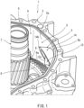
- FIG. 1 is an exploded view of a transmission 2 of a helicopter according to a first embodiment.
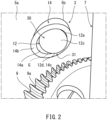
- FIG. 2 is a perspective view of a lubricator 3 of FIG. 1 as viewed from inside a housing 5.
- the internal construction of the transmission 2 is depicted with an upper structure (not shown) removed from the housing 5.
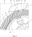
- FIG. 3 is a top view of the lubricator 3 of FIG. 1 .
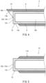
- FIG. 4 is a cross-sectional view of the lubricator 3 of FIG. 1 as viewed in the vertical direction.
- the transmission lubricating assembly 1 of the helicopter lubricates the transmission 2 when the helicopter is in the dry-run situation.
- the transmission lubricating assembly 1 includes the transmission 2 and the lubricator 3.
- the transmission 2 includes a speed change structure 4 and the housing 5.
- the transmission 2 is a main gear box of the helicopter.
- the speed change structure 4 changes the speed of rotation produced by rotational power input from a prime mover of the helicopter and outputs the resulting rotational power.
- the speed change structure 4 of the first embodiment changes the speed of rotation produced by rotational power input from the prime mover and outputs the resulting rotational power to a main rotor and a tail rotor of the helicopter.
- the transmission lubricating assembly 1 is disposed, for example, below the main rotor.
- the speed change structure 4 includes gears 6 and rotating shafts 7 that are rotatably supported.
- the rotating shafts 7 include an input shaft that is rotated at a relatively high speed by the rotational power from the prime mover.
- the gears 6 are secured to the rotating shafts 7.
- the rotating shafts 7 are rotatably supported by bearings (e.g., ball bearings) which are not shown. In normal situations, the gears 6, rotating shafts 7, and bearings are lubricated with a lubricating oil supplied by a lubricating system of the helicopter and operate smoothly.
- the gears 6 include a bevel gear 9 disposed such that a toothed surface 9a of the bevel gear 9 faces upward.
- the toothed surface 9a of the bevel gear 9, which faces upward, extend longitudinally in a horizontal direction.
- the gears 6 of the first embodiment include two or more gears disposed such that the toothed surfaces of the gears face upward.
- the housing 5 includes an internal space S.
- the internal space S of the first embodiment extends in the front-rear, left-right, and up-down directions.
- the housing 5 accommodates the speed change structure 4 in the internal space S.
- a mist of the lubricating oil supplied from the lubricating system usually floats in the internal space S of the housing 5.
- the term "mist” as used herein refers, for example, to an ensemble of liquid particles having a diameter in the order of micrometers or less.
- the housing 5 includes an inner wall 5a surrounding the speed change structure 4.
- the lubricator 3 lubricates the speed change structure 4.
- the lubricator 3 includes a collector 30 and a dropper 31.
- the collector 30 collects the lubricating oil in the internal space S of the housing 5. Specifically, the collector 30 collects the mist of the lubricating oil in the internal space S of the housing 5.
- the dropper 31 is disposed below the collector 30 and applies droplets of the collected lubricating oil to the speed change structure 4. Specifically, the collected mist is gathered into droplets under its own weight, and the dropper 31 applies the droplets of the lubricating oil to the speed change structure 4.
- the mist collected by the lubricator 3 include at least a mist scattered directly from the speed change structure 4 or a mist floating in the internal space S. Drive power for operating the lubricator 3 is not needed as the droplets of the lubricating oil fall under their own weight from the lubricator 3.
- the housing 5 is constructed by a combination of different components.
- the housing 5 includes upper and lower structures combined together in the up-down direction.
- the lubricator 3 is mounted on the housing 5 (on the lower structure in this embodiment).
- the lubricator 3 applies the droplets of the lubricating oil to the toothed surface of at least one of the gears 6 of the speed change structure 4.
- the lubricator 3 of the first embodiment applies the droplets of the lubricating oil to the toothed surface 9a of the bevel gear 9.
- the lubricator 3 of the first embodiment is disposed at a location that allows the lubricating oil droplets falling from the lubricator 3 to lubricate at least one of the gears.
- the application of the lubricating oil droplets to the speed change structure 4 by the lubricator 3 reduces seizure of the speed change structure 4 in the dry-run situation. This lengthens the time taken for seizure of the speed change structure 4 to occur in the dry-run situation.
- the lubricator 3 is mounted on the inner wall 5a of the housing 5.
- the lubricator 3 is mounted on the inner wall 5a of a left or right portion of the housing 5.
- the lubricator 3 is inserted into an insertion hole 5b of the left or right portion of the housing 5 such that the lubricator 3 can be in contact with external air.
- the lubricator 3 includes a shaft structure 12 and a tubular structure 14.
- the shaft structure 12 is inserted in part into the tubular structure 14 such that one axial end of the shaft structure 12 (this axial end may be hereinafter referred to as the "first end" of the shaft structure 12) protrudes out of the tubular structure 14.
- the shaft structure 12 extends in a horizontal direction.
- the tubular structure 14 is disposed so as to enclose an outer peripheral surface 12a of the shaft structure 12, with a gap G defined between an inner peripheral surface 14a of the tubular structure 14 and the outer peripheral surface 12a of the shaft structure 12.
- the shaft structure 12 is in the shape of a circular cylinder.
- the tubular structure 14 is in the shape of a straight pipe.
- the axis of the shaft structure 12 and the axis of the tubular structure 14 coincide with each other.
- the gap G is ring-shaped and has a constant width when viewed in the axial direction of the shaft structure 12, and extends tubularly in the axial direction of the shaft structure 12.
- the collector 30 includes the outer peripheral surface 12a of the shaft structure 12, an end surface 12c of the first end of the shaft structure 12, and the inner peripheral surface 14a of the tubular structure 14.
- the dropper 31 includes a lowermost point 12d of a region of the shaft structure 12 and a lowermost point 14c of a region of the tubular structure 14, the regions facing each other across the gap G.
- the collector 30 of the first embodiment is disposed such that the end surface 12c of the first end of the shaft structure 12 faces in a direction against the direction of rotation of the bevel gear 9 and along a line L that is tangent to an addendum circle 9b along the inner periphery of the bevel gear 9 and that is parallel to the axial direction of the shaft structure 12.
- the lubricator 3 is disposed such that the axial directions of the shaft structure 12 and tubular structure 14 are parallel to the tangent line L in top view.
- the collector 30 is disposed so as to collect a lubricating oil mist scattered from the bevel gear 9 and a lubricating oil mist flowing in the internal space S under the effect of the rotation of the bevel gear 9.
- the shaft structure 12 and the tubular structure 14 may be made of the same material or different materials.
- the shaft structure 12 and tubular structure 14 of the first embodiment are non-magnetic and made of a non-magnetic material such as stainless steel.
- the lubricator 3 can avoid adsorption of magnetic matter such as gear abrasion powder onto the shaft structure 12 and tubular structure 14 in the case where the magnetic matter is mixed in with the lubricating oil present in the housing 5.
- only one of the shaft structure 12 and tubular structure 14 may be non-magnetic. In the case where, for example, the problem of soiling with magnetic matter is not significant, at least one of the shaft structure 12 and tubular structure 14 may be non-magnetic.
- the first end of the shaft structure 12 protrudes out of the first end of the tubular structure 14.
- an end surface 14b of the first end of the tubular structure 14 (the end surface located in the internal space S in this embodiment) forms an angle with the end surface 12c of the shaft structure 12.
- the lowermost points 12d and 14c of the shaft structure 12 and tubular structure 14 are located in a plane including the end surface 12c of the shaft structure 12.
- the lowermost point 12d is located at the boundary between the end surface 12c of the first end of the shaft structure 12 and the outer peripheral surface 12a of the shaft structure 12.
- the lowermost point 14c coincides, for example, with the lowermost point of the inner peripheral surface 14a of the tubular structure 14.
- the speed change structure 4 includes the gears 6, and the lubricator 3 applies the droplets of the lubricating oil to the toothed surface of at least one of the gears 6.
- seizure of the toothed surface of the gear 6 can be reduced to allow the transmission 2 to operate smoothly.
- Droplets of the lubricating oil are retained in the gap G, and the dropper 31 includes the lowermost point12d of a region of the shaft structure 12 and the lowermost point 14c of a region of the tubular structure 14, the regions facing each other across the gap G.
- droplets of the lubricating oil are formed from the mist in the gap G between the shaft structure 12 and the tubular structure 14, and the droplets of the lubricating oil can be applied to a desired site of the speed change structure 4 from the lowermost points 12d and 14c of the shaft structure 12 and the tubular structure 14.
- the shaft structure 12 is shaped as a tube in which the end surface 12c located towards the one axial end of the tubular structure 14 is closed, and includes the hollow interior 12b into which a gas flows from outside the housing 5.
- the outer peripheral surface 12a of the shaft structure 12 can be cooled with the gas to prevent evaporation of the lubricating oil in the gap G. This can prevent the gap G from being clogged with components of the lubricating oil (caulking).
- the lubricator 3 can be used stably over a long period of time. Additionally, the lubricating oil mist collected by the lubricator 3 is cooled on the outer peripheral surface 12a of the shaft structure 12, and formation of the lubricating oil droplets is facilitated.
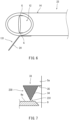
- FIG. 6 is a side view of a lubricator 23 according to a second variant of the first embodiment.
- a dropper 131 of the lubricator 23 includes a guide 24 by which the lubricating oil droplets formed in the gap G are guided to fall to a target site of the speed change structure 4.
- the guide 24 is a strip-shaped metal structure in this variant.
- the guide 24 may be another kind of structure.
- the lubricator 23 can apply the droplets of the lubricating oil to the target site of the speed change structure 4 using the guide 24 even in the case where, for example, there is a limitation to the location of the shaft structure 12 and tubular structure 14.
- a second embodiment will be described with emphasis on differences from the first embodiment.
- FIG. 7 is a side view of a lubricator 33 according to the second embodiment.
- the lubricator 33 includes a mesh structure 34 disposed to contact the lubricating oil mist floating in the internal space S and a bracket 35 supporting the mesh structure 34 and mounted on the inner wall 5a of the housing 5.
- the mesh structure 34 is in the shape of, for example, a circular cone having a lower end as its apex, but is not limited to being in this shape.
- the number and size of the openings of the mesh structure 34 are defined such that the mesh structure 34 can collect the lubricating oil mist floating in the internal space S and form droplets of the lubricating oil.
- a collector 230 includes a mesh portion of the mesh structure 34.
- a dropper 231 includes a lower end of the mesh structure 34.
- the mist of the lubricating oil can be collected by the mesh structure 34, and droplets of the lubricating oil can be easily formed from the collected mist.
- a porous structure such as a sponge may be used instead of the mesh structure 34.
- the shaft structure 12 may be in a shape other than the shape of a circular cylinder and may be, for example, in the shape of a prism.
- the tubular structure 14 may be in a shape other than the shape of a straight pipe and may be, for example, in the shape of a bent pipe.
Landscapes
- Engineering & Computer Science (AREA)
- General Engineering & Computer Science (AREA)
- Mechanical Engineering (AREA)
- Aviation & Aerospace Engineering (AREA)
- Chemical & Material Sciences (AREA)
- Oil, Petroleum & Natural Gas (AREA)
- General Details Of Gearings (AREA)
Claims (10)
- Getriebeschmieranordnung (1) für einen Hubschrauber, wobei die Getriebeschmieranordnung (1) Folgendes umfasst:ein Getriebe (2) mit einer Drehzahländerungsstruktur (4), die dafür eingerichtet ist, in der Lage zu sein, die Drehzahl, die durch eine von einer Antriebsmaschine eingegebene Drehkraft erzeugt wird, zu ändern und die resultierende Drehkraft auszugeben, und einem Gehäuse (5), das die Drehzahländerungsstruktur (4) aufnimmt; undeine Schmiervorrichtung (3, 13, 23), die die Drehzahländerungsstruktur (4) schmiert, wobeidie Schmiervorrichtung (3, 13, 23) einen Sammler (30), der einen Nebel eines Schmieröls in einem Innenraum (S) des Gehäuses (5) sammelt, und einen Tropfer (31, 131) beinhaltet, der unterhalb des Sammlers (30) angeordnet ist und der Tröpfchen des Schmieröls auf die Drehzahländerungsstruktur (4) aufbringt, wobei die aus dem gesammelten Nebel resultierenden Tröpfchen unter seinem eigenen Gewicht gesammelt werden,dadurch gekennzeichnet, dassdie Schmiervorrichtung (3, 13, 23) ferner eine Wellenstruktur (12), die sich in einer horizontalen Richtung erstreckt, und eine röhrenförmige Struktur (14, 114) beinhaltet, die so angeordnet ist, dass sie eine äußere Umfangsfläche der Wellenstruktur (12) umschließt, wobei ein Spalt (G) zwischen einer inneren Umfangsfläche der röhrenförmigen Struktur (14, 114) und der äußeren Umfangsfläche der Wellenstruktur (12) definiert ist,sich ein axiales Ende der röhrenförmigen Struktur (14, 114) unterhalb des anderen axialen Endes der röhrenförmigen Struktur (14, 114) befindet,der Sammler (30) die äußere Umfangsfläche der Wellenstruktur (12), eine Stirnfläche der Wellenstruktur (12) und die innere Umfangsfläche der röhrenförmigen Struktur (14, 114) beinhaltet, wobei sich die Stirnfläche der Wellenstruktur (12) zu dem einen axialen Ende der röhrenförmigen Struktur (14, 114) hin befindet,die Tröpfchen des Schmieröls in dem Spalt (G) zurückgehalten werden, undder Tropfer (31, 131) einen untersten Punkt eines Bereichs der Wellenstruktur (12) und einen untersten Punkt eines Bereichs der röhrenförmigen Struktur (14, 114) beinhaltet, wobei die Bereiche einander über den Spalt (G) hinweg gegenüberliegen.
- Getriebeschmieranordnung (1) nach Anspruch 1, wobei die Schmiervorrichtung (3, 13, 23) an dem Gehäuse (5) montiert ist.
- Getriebeschmieranordnung (1) nach Anspruch 1 oder 2, wobeidie Drehzahländerungsstruktur (4) Zahnräder (6) beinhaltet, unddie Schmiervorrichtung (3, 13, 23) die Tröpfchen des Schmieröls auf eine gezahnte Oberfläche von mindestens einem der Zahnräder (6) aufbringt.
- Getriebeschmieranordnung (1) nach Anspruch 3, wobeidie Zahnräder (6) ein Kegelrad (9) beinhalten, das so angeordnet ist, dass eine gezahnte Oberfläche (9a) des Kegelrads (9) nach oben weist, unddie Schmiervorrichtung (3, 13, 23) die Tröpfchen des Schmieröls auf die gezahnte Oberfläche (9a) des Kegelrads (9) aufbringt.
- Getriebeschmieranordnung (1) nach Anspruch 4, wobei der Sammler (30) in Richtung einer Drehachse des Kegelrads (9) gesehen so angeordnet ist, dass er gegen eine Drehrichtung des Kegelrads (9) gerichtet ist.
- Getriebeschmieranordnung (1) nach einem der Ansprüche 1 bis 5, wobei ein axiales Ende der Wellenstruktur (12) aus dem einen axialen Ende der röhrenförmigen Struktur (14, 114) herausragt.
- Getriebeschmieranordnung (1) nach Anspruch 6, wobei in Draufsichteine Stirnfläche des einen axialen Endes der röhrenförmigen Struktur (14, 114) einen Winkel mit der Stirnfläche der Wellenstruktur (12) bildet, unddie untersten Punkte der Wellenstruktur (12) und der röhrenförmigen Struktur (14, 114) in einer Ebene (14b) liegen, die die Stirnfläche der röhrenförmigen Struktur (14, 114) beinhaltet.
- Getriebeschmieranordnung (1) nach einem der Ansprüche 1 bis 7, wobeidie Wellenstruktur (12) als Rohr geformt ist, bei dem die Stirnfläche, die sich in Richtung des einen axialen Endes der röhrenförmigen Struktur (14, 114) befindet, geschlossen ist, unddie Wellenstruktur (12) einen hohlen Innenraum (12b) beinhaltet, in den ein Gas von außerhalb des Gehäuses (5) strömt.
- Getriebeschmieranordnung (1) nach einem der Ansprüche 1 bis 8, wobei die Wellenstruktur (12) nicht-magnetisch ist.
- Getriebeschmieranordnung (1) nach einem der Ansprüche 1 bis 9, wobei die röhrenförmige Struktur (14, 114) nicht-magnetisch ist.
Applications Claiming Priority (2)
| Application Number | Priority Date | Filing Date | Title |
|---|---|---|---|
| JP2019236612A JP7377103B2 (ja) | 2019-12-26 | 2019-12-26 | ヘリコプターのトランスミッション潤滑構造 |
| PCT/JP2020/047289 WO2021132039A1 (ja) | 2019-12-26 | 2020-12-17 | ヘリコプターのトランスミッション潤滑構造 |
Publications (3)
| Publication Number | Publication Date |
|---|---|
| EP4082902A1 EP4082902A1 (de) | 2022-11-02 |
| EP4082902A4 EP4082902A4 (de) | 2024-01-24 |
| EP4082902B1 true EP4082902B1 (de) | 2025-04-16 |
Family
ID=76574639
Family Applications (1)
| Application Number | Title | Priority Date | Filing Date |
|---|---|---|---|
| EP20905329.7A Active EP4082902B1 (de) | 2019-12-26 | 2020-12-17 | Hubschrauber-getriebe-schmiereinheit |
Country Status (4)
| Country | Link |
|---|---|
| US (1) | US12017760B2 (de) |
| EP (1) | EP4082902B1 (de) |
| JP (1) | JP7377103B2 (de) |
| WO (1) | WO2021132039A1 (de) |
Family Cites Families (13)
| Publication number | Priority date | Publication date | Assignee | Title |
|---|---|---|---|---|
| US2147146A (en) * | 1936-10-16 | 1939-02-14 | Eaton Mfg Co | Automotive drive axle |
| SU411256A1 (de) * | 1971-01-25 | 1974-01-15 | ||
| SU804962A2 (ru) * | 1979-03-11 | 1981-02-15 | Производственное Объединение "Ждановтяжмаш" | Многоступенчатый редуктор |
| SU1486692A2 (ru) * | 1987-05-25 | 1989-06-15 | Gipromashugleobogashche | Редуктор |
| FR2673696B1 (fr) * | 1991-03-07 | 1993-06-18 | Aerospatiale | Procede de refroidissement de reducteurs lubrifies a l'huile pulverisee et appareillage de mise en óoeuvre. |
| DE19830301C2 (de) * | 1998-07-07 | 2003-08-14 | Bosch Gmbh Robert | Verfahren zur Schmierung der Verzahnung einer Getriebeeinheit |
| ATE390349T1 (de) | 2005-06-30 | 2008-04-15 | Agusta Spa | Hubschrauber mit hilfschmierölkreislauf |
| US8528697B2 (en) * | 2008-08-12 | 2013-09-10 | GM Global Technology Operations LLC | Differential lubricant temperature controller |
| US8167758B2 (en) * | 2008-12-08 | 2012-05-01 | American Axle & Manufacturing, Inc. | Drive axle assembly with gear mesh lubrication systems for lubricating gear mesh and/or differential bearings |
| US8475314B2 (en) * | 2010-01-28 | 2013-07-02 | American Axle & Manufacturing, Inc. | Differential assembly with features for improved lubrication |
| DE102013018712B4 (de) * | 2013-11-08 | 2024-09-12 | Sew-Eurodrive Gmbh & Co Kg | Getriebe mit Gehäuse |
| JP6314947B2 (ja) * | 2015-10-02 | 2018-04-25 | トヨタ自動車株式会社 | 動力伝達装置の冷却構造 |
| JP7129183B2 (ja) * | 2018-03-16 | 2022-09-01 | 川崎重工業株式会社 | 歯車減速装置 |
-
2019
- 2019-12-26 JP JP2019236612A patent/JP7377103B2/ja active Active
-
2020
- 2020-12-17 WO PCT/JP2020/047289 patent/WO2021132039A1/ja not_active Ceased
- 2020-12-17 EP EP20905329.7A patent/EP4082902B1/de active Active
-
2022
- 2022-06-24 US US17/848,917 patent/US12017760B2/en active Active
Also Published As
| Publication number | Publication date |
|---|---|
| US20220315211A1 (en) | 2022-10-06 |
| WO2021132039A1 (ja) | 2021-07-01 |
| US12017760B2 (en) | 2024-06-25 |
| EP4082902A4 (de) | 2024-01-24 |
| JP7377103B2 (ja) | 2023-11-09 |
| JP2021105416A (ja) | 2021-07-26 |
| EP4082902A1 (de) | 2022-11-02 |
Similar Documents
| Publication | Publication Date | Title |
|---|---|---|
| US3383937A (en) | Lubricating means for transmission and bearing means | |
| CN108930779A (zh) | 变速器的润滑结构 | |
| JP6580047B2 (ja) | 給油路を有する車両動力伝達ユニット(ptu) | |
| KR102039592B1 (ko) | 수직 2단으로 인접한 기어트레인들의 윤활장치 | |
| US11662013B2 (en) | Stalactite passive lubrication system | |
| US10179478B2 (en) | Axle assembly for drive device of a motor vehicle | |
| RU2624931C1 (ru) | Конструкция для смазки и коробка передач | |
| CN115388157B (zh) | 一种齿轮箱润滑系统及传动齿轮箱 | |
| US10760613B2 (en) | Rotary device | |
| JP6275392B2 (ja) | 歯車装置 | |
| US12017760B2 (en) | Transmission lubricating assembly of helicopter | |
| CN106884960B (zh) | 差速器 | |
| JP6122786B2 (ja) | ディファレンシャル装置の潤滑構造 | |
| JP2018112306A (ja) | 動力装置 | |
| US20110030504A1 (en) | Torque-transmitting device comprising an oil recuperator wiper | |
| JP2002266876A (ja) | 転がり軸受 | |
| US20140221145A1 (en) | In situ gearbox greasing system | |
| JP2003214532A (ja) | 潤滑装置 | |
| EP4686857A1 (de) | Anordnung zur schmierung | |
| CN114370506B (zh) | 密封装置 | |
| JPH08383Y2 (ja) | 紡機における歯車のオイル潤滑装置 | |
| JP2009138899A (ja) | ディファレンシャル装置 | |
| JP2019011800A (ja) | 動力伝達装置 | |
| JP6327979B2 (ja) | 自動給油装置 | |
| CN120845382A (zh) | 压缩机 |
Legal Events
| Date | Code | Title | Description |
|---|---|---|---|
| STAA | Information on the status of an ep patent application or granted ep patent |
Free format text: STATUS: THE INTERNATIONAL PUBLICATION HAS BEEN MADE |
|
| PUAI | Public reference made under article 153(3) epc to a published international application that has entered the european phase |
Free format text: ORIGINAL CODE: 0009012 |
|
| STAA | Information on the status of an ep patent application or granted ep patent |
Free format text: STATUS: REQUEST FOR EXAMINATION WAS MADE |
|
| 17P | Request for examination filed |
Effective date: 20220707 |
|
| AK | Designated contracting states |
Kind code of ref document: A1 Designated state(s): AL AT BE BG CH CY CZ DE DK EE ES FI FR GB GR HR HU IE IS IT LI LT LU LV MC MK MT NL NO PL PT RO RS SE SI SK SM TR |
|
| DAV | Request for validation of the european patent (deleted) | ||
| DAX | Request for extension of the european patent (deleted) | ||
| A4 | Supplementary search report drawn up and despatched |
Effective date: 20240103 |
|
| RIC1 | Information provided on ipc code assigned before grant |
Ipc: F16H 57/04 20100101ALI20231220BHEP Ipc: B64C 27/14 20060101AFI20231220BHEP |
|
| GRAP | Despatch of communication of intention to grant a patent |
Free format text: ORIGINAL CODE: EPIDOSNIGR1 |
|
| STAA | Information on the status of an ep patent application or granted ep patent |
Free format text: STATUS: GRANT OF PATENT IS INTENDED |
|
| RIN1 | Information on inventor provided before grant (corrected) |
Inventor name: HASHIMOTO, HIRONORI Inventor name: TANAKA, MITSUAKI Inventor name: SHINODA, YUJI Inventor name: ARISAWA, HIDENORI Inventor name: YAMAMOTO, HIROKI Inventor name: HAYASAKA, AKIRA Inventor name: OGASAWARA, KENTA |
|
| INTG | Intention to grant announced |
Effective date: 20241223 |
|
| GRAS | Grant fee paid |
Free format text: ORIGINAL CODE: EPIDOSNIGR3 |
|
| GRAA | (expected) grant |
Free format text: ORIGINAL CODE: 0009210 |
|
| STAA | Information on the status of an ep patent application or granted ep patent |
Free format text: STATUS: THE PATENT HAS BEEN GRANTED |
|
| AK | Designated contracting states |
Kind code of ref document: B1 Designated state(s): AL AT BE BG CH CY CZ DE DK EE ES FI FR GB GR HR HU IE IS IT LI LT LU LV MC MK MT NL NO PL PT RO RS SE SI SK SM TR |
|
| REG | Reference to a national code |
Ref country code: GB Ref legal event code: FG4D |
|
| REG | Reference to a national code |
Ref country code: CH Ref legal event code: EP |
|
| REG | Reference to a national code |
Ref country code: IE Ref legal event code: FG4D |
|
| REG | Reference to a national code |
Ref country code: DE Ref legal event code: R096 Ref document number: 602020049740 Country of ref document: DE |
|
| REG | Reference to a national code |
Ref country code: NL Ref legal event code: MP Effective date: 20250416 |
|
| PG25 | Lapsed in a contracting state [announced via postgrant information from national office to epo] |
Ref country code: NL Free format text: LAPSE BECAUSE OF FAILURE TO SUBMIT A TRANSLATION OF THE DESCRIPTION OR TO PAY THE FEE WITHIN THE PRESCRIBED TIME-LIMIT Effective date: 20250416 |
|
| REG | Reference to a national code |
Ref country code: AT Ref legal event code: MK05 Ref document number: 1785471 Country of ref document: AT Kind code of ref document: T Effective date: 20250416 |
|
| PG25 | Lapsed in a contracting state [announced via postgrant information from national office to epo] |
Ref country code: FI Free format text: LAPSE BECAUSE OF FAILURE TO SUBMIT A TRANSLATION OF THE DESCRIPTION OR TO PAY THE FEE WITHIN THE PRESCRIBED TIME-LIMIT Effective date: 20250416 Ref country code: PT Free format text: LAPSE BECAUSE OF FAILURE TO SUBMIT A TRANSLATION OF THE DESCRIPTION OR TO PAY THE FEE WITHIN THE PRESCRIBED TIME-LIMIT Effective date: 20250818 Ref country code: ES Free format text: LAPSE BECAUSE OF FAILURE TO SUBMIT A TRANSLATION OF THE DESCRIPTION OR TO PAY THE FEE WITHIN THE PRESCRIBED TIME-LIMIT Effective date: 20250416 |
|
| REG | Reference to a national code |
Ref country code: LT Ref legal event code: MG9D |
|
| PG25 | Lapsed in a contracting state [announced via postgrant information from national office to epo] |
Ref country code: GR Free format text: LAPSE BECAUSE OF FAILURE TO SUBMIT A TRANSLATION OF THE DESCRIPTION OR TO PAY THE FEE WITHIN THE PRESCRIBED TIME-LIMIT Effective date: 20250717 Ref country code: NO Free format text: LAPSE BECAUSE OF FAILURE TO SUBMIT A TRANSLATION OF THE DESCRIPTION OR TO PAY THE FEE WITHIN THE PRESCRIBED TIME-LIMIT Effective date: 20250716 |
|
| PG25 | Lapsed in a contracting state [announced via postgrant information from national office to epo] |
Ref country code: PL Free format text: LAPSE BECAUSE OF FAILURE TO SUBMIT A TRANSLATION OF THE DESCRIPTION OR TO PAY THE FEE WITHIN THE PRESCRIBED TIME-LIMIT Effective date: 20250416 |
|
| PG25 | Lapsed in a contracting state [announced via postgrant information from national office to epo] |
Ref country code: BG Free format text: LAPSE BECAUSE OF FAILURE TO SUBMIT A TRANSLATION OF THE DESCRIPTION OR TO PAY THE FEE WITHIN THE PRESCRIBED TIME-LIMIT Effective date: 20250416 |
|
| PG25 | Lapsed in a contracting state [announced via postgrant information from national office to epo] |
Ref country code: HR Free format text: LAPSE BECAUSE OF FAILURE TO SUBMIT A TRANSLATION OF THE DESCRIPTION OR TO PAY THE FEE WITHIN THE PRESCRIBED TIME-LIMIT Effective date: 20250416 |
|
| PG25 | Lapsed in a contracting state [announced via postgrant information from national office to epo] |
Ref country code: AT Free format text: LAPSE BECAUSE OF FAILURE TO SUBMIT A TRANSLATION OF THE DESCRIPTION OR TO PAY THE FEE WITHIN THE PRESCRIBED TIME-LIMIT Effective date: 20250416 |
|
| PG25 | Lapsed in a contracting state [announced via postgrant information from national office to epo] |
Ref country code: RS Free format text: LAPSE BECAUSE OF FAILURE TO SUBMIT A TRANSLATION OF THE DESCRIPTION OR TO PAY THE FEE WITHIN THE PRESCRIBED TIME-LIMIT Effective date: 20250716 |
|
| PG25 | Lapsed in a contracting state [announced via postgrant information from national office to epo] |
Ref country code: IS Free format text: LAPSE BECAUSE OF FAILURE TO SUBMIT A TRANSLATION OF THE DESCRIPTION OR TO PAY THE FEE WITHIN THE PRESCRIBED TIME-LIMIT Effective date: 20250816 |
|
| PG25 | Lapsed in a contracting state [announced via postgrant information from national office to epo] |
Ref country code: LV Free format text: LAPSE BECAUSE OF FAILURE TO SUBMIT A TRANSLATION OF THE DESCRIPTION OR TO PAY THE FEE WITHIN THE PRESCRIBED TIME-LIMIT Effective date: 20250416 |
|
| PGFP | Annual fee paid to national office [announced via postgrant information from national office to epo] |
Ref country code: GB Payment date: 20251106 Year of fee payment: 6 |
|
| PG25 | Lapsed in a contracting state [announced via postgrant information from national office to epo] |
Ref country code: SM Free format text: LAPSE BECAUSE OF FAILURE TO SUBMIT A TRANSLATION OF THE DESCRIPTION OR TO PAY THE FEE WITHIN THE PRESCRIBED TIME-LIMIT Effective date: 20250416 Ref country code: DK Free format text: LAPSE BECAUSE OF FAILURE TO SUBMIT A TRANSLATION OF THE DESCRIPTION OR TO PAY THE FEE WITHIN THE PRESCRIBED TIME-LIMIT Effective date: 20250416 |
|
| PGFP | Annual fee paid to national office [announced via postgrant information from national office to epo] |
Ref country code: FR Payment date: 20251106 Year of fee payment: 6 |
|
| REG | Reference to a national code |
Ref country code: DE Ref legal event code: R097 Ref document number: 602020049740 Country of ref document: DE |
|
| PG25 | Lapsed in a contracting state [announced via postgrant information from national office to epo] |
Ref country code: CZ Free format text: LAPSE BECAUSE OF FAILURE TO SUBMIT A TRANSLATION OF THE DESCRIPTION OR TO PAY THE FEE WITHIN THE PRESCRIBED TIME-LIMIT Effective date: 20250416 |
|
| PG25 | Lapsed in a contracting state [announced via postgrant information from national office to epo] |
Ref country code: EE Free format text: LAPSE BECAUSE OF FAILURE TO SUBMIT A TRANSLATION OF THE DESCRIPTION OR TO PAY THE FEE WITHIN THE PRESCRIBED TIME-LIMIT Effective date: 20250416 |
|
| PG25 | Lapsed in a contracting state [announced via postgrant information from national office to epo] |
Ref country code: SK Free format text: LAPSE BECAUSE OF FAILURE TO SUBMIT A TRANSLATION OF THE DESCRIPTION OR TO PAY THE FEE WITHIN THE PRESCRIBED TIME-LIMIT Effective date: 20250416 |
|
| PG25 | Lapsed in a contracting state [announced via postgrant information from national office to epo] |
Ref country code: IT Free format text: LAPSE BECAUSE OF FAILURE TO SUBMIT A TRANSLATION OF THE DESCRIPTION OR TO PAY THE FEE WITHIN THE PRESCRIBED TIME-LIMIT Effective date: 20250416 |
|
| PG25 | Lapsed in a contracting state [announced via postgrant information from national office to epo] |
Ref country code: RO Free format text: LAPSE BECAUSE OF FAILURE TO SUBMIT A TRANSLATION OF THE DESCRIPTION OR TO PAY THE FEE WITHIN THE PRESCRIBED TIME-LIMIT Effective date: 20250416 |
|
| PLBE | No opposition filed within time limit |
Free format text: ORIGINAL CODE: 0009261 |
|
| STAA | Information on the status of an ep patent application or granted ep patent |
Free format text: STATUS: NO OPPOSITION FILED WITHIN TIME LIMIT |
|
| REG | Reference to a national code |
Ref country code: CH Ref legal event code: L10 Free format text: ST27 STATUS EVENT CODE: U-0-0-L10-L00 (AS PROVIDED BY THE NATIONAL OFFICE) Effective date: 20260225 |
|
| 26N | No opposition filed |
Effective date: 20260119 |
|
| PG25 | Lapsed in a contracting state [announced via postgrant information from national office to epo] |
Ref country code: LT Free format text: LAPSE BECAUSE OF FAILURE TO SUBMIT A TRANSLATION OF THE DESCRIPTION OR TO PAY THE FEE WITHIN THE PRESCRIBED TIME-LIMIT Effective date: 20250416 |
|
| PG25 | Lapsed in a contracting state [announced via postgrant information from national office to epo] |
Ref country code: MC Free format text: LAPSE BECAUSE OF FAILURE TO SUBMIT A TRANSLATION OF THE DESCRIPTION OR TO PAY THE FEE WITHIN THE PRESCRIBED TIME-LIMIT Effective date: 20250416 |
|
| PGFP | Annual fee paid to national office [announced via postgrant information from national office to epo] |
Ref country code: DE Payment date: 20251106 Year of fee payment: 6 |
|
| REG | Reference to a national code |
Ref country code: CH Ref legal event code: H13 Free format text: ST27 STATUS EVENT CODE: U-0-0-H10-H13 (AS PROVIDED BY THE NATIONAL OFFICE) Effective date: 20260723 |
|
| PG25 | Lapsed in a contracting state [announced via postgrant information from national office to epo] |
Ref country code: SE Free format text: LAPSE BECAUSE OF FAILURE TO SUBMIT A TRANSLATION OF THE DESCRIPTION OR TO PAY THE FEE WITHIN THE PRESCRIBED TIME-LIMIT Effective date: 20250416 |