EP4082684A1 - Method of manufacturing ring-rolled element - Google Patents
Method of manufacturing ring-rolled element Download PDFInfo
- Publication number
- EP4082684A1 EP4082684A1 EP20908430.0A EP20908430A EP4082684A1 EP 4082684 A1 EP4082684 A1 EP 4082684A1 EP 20908430 A EP20908430 A EP 20908430A EP 4082684 A1 EP4082684 A1 EP 4082684A1
- Authority
- EP
- European Patent Office
- Prior art keywords
- ring
- face
- ring material
- rolling
- slope
- Prior art date
- Legal status (The legal status is an assumption and is not a legal conclusion. Google has not performed a legal analysis and makes no representation as to the accuracy of the status listed.)
- Granted
Links
Images


Classifications
-
- B—PERFORMING OPERATIONS; TRANSPORTING
- B21—MECHANICAL METAL-WORKING WITHOUT ESSENTIALLY REMOVING MATERIAL; PUNCHING METAL
- B21H—MAKING PARTICULAR METAL OBJECTS BY ROLLING, e.g. SCREWS, WHEELS, RINGS, BARRELS, BALLS
- B21H1/00—Making articles shaped as bodies of revolution
- B21H1/06—Making articles shaped as bodies of revolution rings of restricted axial length
-
- B—PERFORMING OPERATIONS; TRANSPORTING
- B21—MECHANICAL METAL-WORKING WITHOUT ESSENTIALLY REMOVING MATERIAL; PUNCHING METAL
- B21H—MAKING PARTICULAR METAL OBJECTS BY ROLLING, e.g. SCREWS, WHEELS, RINGS, BARRELS, BALLS
- B21H9/00—Feeding arrangements for rolling machines or apparatus manufacturing articles dealt with in this subclass
Definitions
- the present invention relates to a method for manufacturing a ring-rolled member.
- a method for manufacturing a ring-rolled member by ring-rolling a ring material for example, as disclosed in JP 5895111 B1 , a method has been known in which a main roll and a mandrel roll are respectively brought into contact with an outer peripheral face and an inner peripheral face of a ring material having a ring-like shape, the ring material is sandwiched and compressed in a radial direction of the ring material by the main roll and the mandrel roll being respectively rotated around their central axes, and the ring material is sandwiched and compressed by a pair of axial rolls in a central axis direction of the ring material, whereby a ring-rolled member is manufactured.
- CN 107127279 A discloses a ring-rolling method in which a main roll is provided with a lower supporting plate positioned below a ring material and an upper compression plate positioned above the ring material, and an upper compression plate adjustment ring member adjusts the position of the upper compression plate to be compatible with ring materials with different heights.
- a method of providing the main roll with flange portions positioned on upper and lower sides of the ring material to stabilize the attitude of the ring material may be employed; however, if the ring material is churned during the ring-rolling and comes into contact with the main roll including the flange portions and the mandrel roll, a problem may occur such as a defect, for example, a burr, is generated in the resulting ring-rolled member, or an increased burden on the ring-rolling device due to an impact of such contact.
- an object of the present invention is to provide a ring-rolled member manufacturing method enabling stabilization of the attitude of the ring material during rolling without generating a defect and the like in the resulting ring-rolled member even when the main roll is provided with the flange portions positioned on upper and lower sides of the ring material.
- the present invention provides a ring-rolled member manufacturing method of manufacturing a ring-rolled member by ring-rolling a ring material with a ring-rolling device, in which: the ring-rolling device is provided with a main roll and a mandrel roll; an outer peripheral face of the main roll includes a recessed portion to accommodate the ring material and an outer peripheral face of the mandrel roll, a first flange portion positioned on one side in a central axis direction of the main roll with respect to the recessed portion, and a second flange portion positioned on an opposite side of the first flange portion; an inner face of the recessed portion includes a rolling face to be in contact with an outer peripheral face of the ring material, a first inner face on a side of the first flange portion, and a second inner face on a side of the second flange portion; and at least one inner face among the first inner face and the second inner face has a slope in such a way that
- the slope starts from within a range of a distance corresponding to a thickness of the ring-rolled member from a line of intersection between the at least one inner face and the rolling face. In other words, a distance between the line of intersection between the at least one inner face and the rolling face and a terminal of the slope on the side of the rolling face is less than the thickness of the ring-rolled member.
- An angle of the slope is greater than 0.3° and no greater than 9° with reference to the perpendicular plane.
- the ring material is preferably a heat-resistant alloy, which is a Ni-based alloy, a Co-based alloy, or an Fe-based alloy.
- the outer peripheral face of the ring material may be at least partially inclined with respect to a central axis of the ring material, and in this case, an angle between a straight line connecting an end face corner of a large-diameter outer periphery with an end face corner of a small-diameter outer periphery of the ring material and the central axis of the ring material may be greater than 10°.
- the angle of the inclination is greater than 10°
- the angle of the slope of the inner face is preferably no less than 0.6° and no greater than 9° with reference to the perpendicular plane.
- the lower limit of the angle of the slope is preferably no less than 0.8°, and more preferably no less than 1°.
- the upper limit of the angle of the slope is preferably no greater than 4°, and more preferably no greater than 3°.
- the outer peripheral face of the ring material may be at least partially inclined with respect to a central axis of the ring material, and in this case, an angle between a straight line connecting an end face corner of a large-diameter outer periphery with an end face corner of a small-diameter outer periphery of the ring material and the central axis of the ring material may be no greater than 10°.
- the angle of the inclination is no greater than 10°
- the angle of the slope of the inner face is preferably greater than 0.3° and less than 3° with reference to the perpendicular plane.
- the lower limit of the preferred angle of the slope is preferably no less than 0.5°, and more preferably no less than 0.6°.
- the upper limit of the angle of the slope is preferably no greater than 2.5°, and more preferably no greater than 2°.
- the outer peripheral face of the main roll includes the recessed portion to accommodate the ring material and the outer peripheral face of the mandrel roll, and the at least one inner face among the first inner face on the side of the first flange portion and the second inner face on the side of the second flange portion of the recessed portion has the slope on an entire face thereof or in a predetermined part thereof, in such a way that the opening of the recessed portion is enlarged, whereby the ring material being rotated is appropriately constrained and an attitude thereof can be stabilized, enabling smooth ring-rolling.
- it is not required to prepare a plurality of patterns of dies or increase the heat number, whereby the cost required for the ring-rolling can be reduced.
- the attitude of the ring material can be stabilized, whereby a nearly net shape can be given to the resulting ring-rolled member and an input weight of the ring material can be reduced.
- the ring-rolling device shown in Fig. 1 to Fig. 4 is used, for example.
- the ring-rolling device is provided with a main roll 10 and a mandrel roll 20 that are positioned respectively on an outer peripheral side and an inner peripheral side of a ring material 1, which is a rolling target, having a ring-like shape.
- An outer peripheral face of the main roll 10 and an outer peripheral face of the mandrel roll 20 face each other across the ring material 1.
- the main roll 10 is configured to be rotatable around a central axis 10X thereof, and the mandrel roll 20 is also configured to be rotatable around a central axis 20X thereof.
- the central axis 10X of the main roll 10 and the central axis 20X of the mandrel roll 20 are substantially parallel.
- the main roll 10 and the mandrel roll 20 are configured to roll the ring material 1 in a radial direction of the ring-like shape (hereinafter referred to as "ring radial direction") therebetween, and the mandrel roll 20 is configured to be movable along the ring radial direction with respect to the main roll 10.
- ring radial direction a radial direction of the ring-like shape
- the ring-rolling device is provided with a pair of axial rolls 30 positioned to sandwich the ring material 1 in the central axis direction of the ring-like shape (hereinafter referred to as "ring axis direction").
- ring axis direction the upper side and the lower side in Fig. 2 are referred to as “upper side” and “lower side”, respectively, along the central axis 10X or the central axis 20X.
- the pair of axial rolls 30 are positioned on the upper and lower sides of the ring material 1.
- the pair of axial rolls 30 are configured to roll the ring material 1 in the ring axis direction, and outer peripheral faces of the pair of axial rolls 30 face each other across the ring material 1.
- the pair of axial rolls 30 are configured to be rotatable around the respective central axes thereof.
- the outer peripheral face of the main roll 10 includes a substantially U-shaped recessed portion 12 to accommodate the ring material 1, which is the rolling target, and the outer peripheral face of the mandrel roll 20, a first flange portion (hereinafter referred to as “upper flange portion”) 11 positioned on one side in the central axis direction of the main roll, and a second flange portion (hereinafter referred to as “lower flange portion”) 13 positioned on an opposite side of the first flange portion 11.
- an inner face of the recessed portion 12 of the main roll 10 includes a rolling face 12S to be in contact with the outer peripheral face of the ring material 1, a first inner face (hereinafter referred to as "upper face”) 11S on a side of the upper flange portion 11, and a second inner face (hereinafter referred to as "lower face”) 13S on a side of the lower flange portion 13.
- the rolling face 12S of the recessed portion 12 of the main roll 10 is inclined to correspond to the outer peripheral face of the ring-rolled member after the rolling.
- the outer peripheral face 20S of the mandrel roll 20 is also inclined to correspond to the inner peripheral face of the ring-rolled member after the rolling.
- a gap between the rolling face 12S of the recessed portion 12 of the main roll 10 and the outer peripheral face 20S of the mandrel roll 20 has a shape of the ring-rolled member after the rolling.
- the rolling face 12S of the recessed portion 12 of the main roll 10 and the outer peripheral face 20S of the mandrel roll 20 correspond respectively to desired shapes of the outer peripheral face and the inner peripheral face of the ring-rolled member, and may be inclined in a linear shape, a curved shape, or a combination thereof.
- the thickness of the ring-rolled member is not required to be uniform, and therefore the inclinations of the outer peripheral face and the inner peripheral face of the ring-rolled member are not required to be at the same angle.
- the lower face 13S of the recessed portion 12 of the main roll 10 has, as shown in Fig. 2 , a slope in such a way that the opening of the recessed portion 12 is enlarged toward the outer peripheral side of the main roll 10.
- the lower face 13S since the lower face 13S is larger in area than the upper face 11S, the lower face 13S has the slope; however, depending on the desired shape of the ring-rolled member, in a case in which the upper face 11S is larger in area than the lower face 13S, the upper face 11S has a slope in such a way that the opening of the recessed portion 12 is enlarged toward the outer peripheral side.
- the upper face 11S may have slopes.
- the slope angle ⁇ a of the upper face 11S is indicated by, as shown in Fig. 3 , an angle between a perpendicular plane H perpendicularly intersecting the central axis direction of the main roll (typically a horizontal face in the ring radial direction) and the upper face 11S.
- the lower limit of the slope angle ⁇ a of the upper face 11S varies according to an inclination angle, which is described later, of the ring material, but is preferably greater than 0.3°, more preferably no less than 0.5°, still more preferably no less than 0.6°, and further more preferably no less than 1°.
- the upper limit of the slope angle ⁇ a of the upper face 11S is preferably no greater than 9°, more preferably less than 5°, still more preferably no greater than 3°, and further more preferably no greater than 2°.
- the slope of the upper face 11S is provided, as shown in Fig. 3 , from a line of intersection V with the rolling face 12S of the recessed portion 12 of the main roll 10 to an end on the outer peripheral side (in other words, on an entire face of the upper face 11S); however, in order to produce the effects of the invention, it is only required to provide the slope, not from the line of intersection V with the rolling face 12S, but from a position Sa of the inner peripheral face of the desired ring-rolled member after rolling to the end on the outer peripheral side (in other words, a distance between the line of intersection V and the position Sa is a thickness Ra of an upper end portion of the desired ring-rolled member). In other words, a distance between the line of intersection V between the upper face 11S and the rolling face 12S and a terminal of the slope of the upper face 11S on the side of the rolling face 12S is less than the thickness Ra of the ring-rolled member.
- the slope angle ⁇ b of the lower face 13S is indicated by, as shown in Fig. 4 , an angle between the perpendicular plane H perpendicularly intersecting the central axis direction of the main roll 10 (typically a horizontal face in the ring radial direction) and the lower face 13S.
- the lower limit of the slope angle ⁇ b of the lower face 13S varies according to an inclination angle, which is described later, of the ring material, but is preferably no less than 0.3°, more preferably no less than 0.5°, still more preferably no less than 0.6°, and further more preferably no less than 1°.
- the upper limit of the slope angle ⁇ b of the lower face 13 S varies according to an inclination angle, which is described later, of the ring material, but is preferably less than 9°, more preferably less than 5°, still more preferably less than 3°, and further more preferably less than 2°.
- the slope of the lower face 13S is provided, as shown in Fig. 4 , from a line of intersection V with the rolling face 12S of the recessed portion 12 of the main roll 10 to an end on the outer peripheral side (in other words, on an entire face of the lower face 13S); however, in order to produce the effects of the invention, it is only required to provide the slope, not from the line of intersection V with the rolling face 12S, but from a position Sb of the inner peripheral face of the desired ring-rolled member after rolling to the end on the outer peripheral side (in other words, a distance between the line of intersection V and the position Sb is a thickness Rb of a lower end portion of the desired ring-rolled member). In other words, a distance between the line of intersection V between the lower face 13 S and the rolling face 12S and a terminal of the slope of the lower face 13S on the side of the rolling face 12S is less than the thickness Rb of the ring-rolled member.
- the ring material 1 is loaded to the ring-rolling device.
- a material formed from a heat-resistant alloy such as a Ni-based alloy, a Co-based alloy, and an Fe-based alloy is suitable. Since hot ductility of the heat-resistant alloy is significantly reduced due to a decrease in temperature, a temperature range in which the heat-resistant alloy can be plastically processed is extremely narrow. In other words, the heat-resistant alloy is rollable only for a short period of time. Therefore, the ring-rolling device according to the present embodiment enabling rolling in a stable attitude provides a profound effect.
- the heating temperature for the ring material 1 loaded to the ring-rolling device varies according to the material of the ring material 1.
- the heating temperature is preferably in a range from 1000 °C to 1050 °C; however, the heating temperature may vary according to a demand of a product and is not limited to this range.
- the shape of the ring material 1 to be loaded may be, for example, a so-called tapered ring with an outer peripheral face and an inner peripheral face being linearly inclined substantially uniformly, and a so-called odd-shaped ring being inclined in a curved shape or in a combination of a linear shape and a curved shape, or having a thickness which is partially different.
- the inclination angle ⁇ r of the ring material 1 as described above is indicated by, even in the case in which the thickness of a part of the ring material is different as shown in Fig.
- the lower limit of the inclination angle ⁇ r of the ring material 1 is preferably no less than 5°, more preferably no less than 7°, still more preferably greater than 10°, and further more preferably no less than 15°.
- the upper limit of the inclination angle ⁇ r of the ring material 1 is not particularly limited, and preferably no greater than 40°, more preferably no greater than 35°, and still more preferably no greater than 30°.
- the ring material 1 to be loaded may be, of course, a so-called rectangular ring without inclination.
- the outer peripheral face of the main roll 10 and the outer peripheral face of the mandrel roll 20 are brought into contact with the outer peripheral face and the inner peripheral face of the ring material 1, and the outer peripheral faces of the pair of axial rolls 30 are brought into contact with both of the upper and lower end faces of the ring material 1 respectively.
- the mandrel roll 20 is moved toward the main roll 10, whereby the main roll 10 and the mandrel roll 20 sandwich and compress the ring material 1 in the ring radial direction.
- the pair of axial rolls 30 are rotated in the direction of the arrow shown in Fig. 1
- the pair of axial rolls 30 sandwich and compress the ring material 1 in the ring axis direction.
- the ring material 1 is thus ring-rolled to yield a ring-rolled member.
- the ring material 1 is a tapered ring or an odd-shaped ring
- the lower face 13S of the recessed portion 12 of the main roll 10 has a slope in such a way that the opening of the recessed portion 12 is enlarged toward the outer peripheral side of the main roll 10 as shown in Fig. 2
- the attitude of the ring material 1 accommodated in the recessed portion 12 of the main roll 10 is stabilized by the lower face 13S and the upper face 11S of the recessed portion 12, whereby stable rotation of the ring material 1 around the central axis 1X is enabled.
- This can suppress excessive contact of the ring material 1 with the axial roll 30 and the like, and in turn prevent generation of a defect.
- the test was carried out for two types of ring material: a tapered ring with an inclination angle of greater than 10°; and a tapered ring with an inclination angle of no greater than 10°.
- the rolling stability was superior when the slope angle was in a range of no less than 0.6° and no greater than 9°, and both of the rolling stability and defect prevention were remarkably superior when the slope angle was in a range of no less than 1° and less than 3°.
Landscapes
- Engineering & Computer Science (AREA)
- Mechanical Engineering (AREA)
- Reduction Rolling/Reduction Stand/Operation Of Reduction Machine (AREA)
Abstract
Description
- The present invention relates to a method for manufacturing a ring-rolled member.
- As a method for manufacturing a ring-rolled member by ring-rolling a ring material, for example, as disclosed in
JP 5895111 B1 - In addition, as a ring-rolled member manufacturing method, for example,
CN 107127279 A discloses a ring-rolling method in which a main roll is provided with a lower supporting plate positioned below a ring material and an upper compression plate positioned above the ring material, and an upper compression plate adjustment ring member adjusts the position of the upper compression plate to be compatible with ring materials with different heights. -
- Patent Document 1:
JP 5895111 B1 - Patent Document 2:
CN 107127279 A - In the case of ring-rolling a ring material, especially when the ring material has a tapered shape or such a shape that thickness thereof is partially different, resistance generated by a difference in peripheral speed between the main roll and the mandrel roll, which are dies, and the ring material, and a difference in an increase in diameter between a thick-walled portion and a thin-walled portion, lead to a problem of an attitude of the ring material being difficult to stabilize during the ring-rolling. When rotation of the ring material is unstable, the ring material may be excessively brought into contact with the axial roll and a table, leading to problems of generation of a defect, deflection of the shape of the ring-rolled member after the rolling, and the like.
- In order to stabilize the rotation of the ring material, a method of providing the main roll with flange portions positioned on upper and lower sides of the ring material to stabilize the attitude of the ring material may be employed; however, if the ring material is churned during the ring-rolling and comes into contact with the main roll including the flange portions and the mandrel roll, a problem may occur such as a defect, for example, a burr, is generated in the resulting ring-rolled member, or an increased burden on the ring-rolling device due to an impact of such contact. Therefore, in the case of providing the main roll with the flange portions as described above, it has been necessary to prepare a plurality of patterns of the shape of the main roll including the flange portions (so-called die) and carry out the ring-rolling while adjusting contact with the ring material, and to carry out the ring-rolling little by little through a large number of steps of heating and then ring-rolling the ring material (increasing so-called heat number) in order to alleviate the burden on the device, for example.
- In view of the above-described problems, an object of the present invention is to provide a ring-rolled member manufacturing method enabling stabilization of the attitude of the ring material during rolling without generating a defect and the like in the resulting ring-rolled member even when the main roll is provided with the flange portions positioned on upper and lower sides of the ring material.
- In order to achieve the aforementioned object, the present invention provides a ring-rolled member manufacturing method of manufacturing a ring-rolled member by ring-rolling a ring material with a ring-rolling device, in which: the ring-rolling device is provided with a main roll and a mandrel roll; an outer peripheral face of the main roll includes a recessed portion to accommodate the ring material and an outer peripheral face of the mandrel roll, a first flange portion positioned on one side in a central axis direction of the main roll with respect to the recessed portion, and a second flange portion positioned on an opposite side of the first flange portion; an inner face of the recessed portion includes a rolling face to be in contact with an outer peripheral face of the ring material, a first inner face on a side of the first flange portion, and a second inner face on a side of the second flange portion; and at least one inner face among the first inner face and the second inner face has a slope in such a way that an opening of the recessed portion is enlarged, with reference to a perpendicular plane perpendicularly intersecting the central axis direction of the main roll. The slope starts from within a range of a distance corresponding to a thickness of the ring-rolled member from a line of intersection between the at least one inner face and the rolling face. In other words, a distance between the line of intersection between the at least one inner face and the rolling face and a terminal of the slope on the side of the rolling face is less than the thickness of the ring-rolled member. An angle of the slope is greater than 0.3° and no greater than 9° with reference to the perpendicular plane.
- The ring material is preferably a heat-resistant alloy, which is a Ni-based alloy, a Co-based alloy, or an Fe-based alloy.
- The outer peripheral face of the ring material may be at least partially inclined with respect to a central axis of the ring material, and in this case, an angle between a straight line connecting an end face corner of a large-diameter outer periphery with an end face corner of a small-diameter outer periphery of the ring material and the central axis of the ring material may be greater than 10°. In addition, when the angle of the inclination is greater than 10°, the angle of the slope of the inner face is preferably no less than 0.6° and no greater than 9° with reference to the perpendicular plane. The lower limit of the angle of the slope is preferably no less than 0.8°, and more preferably no less than 1°. The upper limit of the angle of the slope is preferably no greater than 4°, and more preferably no greater than 3°.
- The outer peripheral face of the ring material may be at least partially inclined with respect to a central axis of the ring material, and in this case, an angle between a straight line connecting an end face corner of a large-diameter outer periphery with an end face corner of a small-diameter outer periphery of the ring material and the central axis of the ring material may be no greater than 10°. In addition, when the angle of the inclination is no greater than 10°, the angle of the slope of the inner face is preferably greater than 0.3° and less than 3° with reference to the perpendicular plane. The lower limit of the preferred angle of the slope is preferably no less than 0.5°, and more preferably no less than 0.6°. The upper limit of the angle of the slope is preferably no greater than 2.5°, and more preferably no greater than 2°.
- As described above, in the present invention, the outer peripheral face of the main roll includes the recessed portion to accommodate the ring material and the outer peripheral face of the mandrel roll, and the at least one inner face among the first inner face on the side of the first flange portion and the second inner face on the side of the second flange portion of the recessed portion has the slope on an entire face thereof or in a predetermined part thereof, in such a way that the opening of the recessed portion is enlarged, whereby the ring material being rotated is appropriately constrained and an attitude thereof can be stabilized, enabling smooth ring-rolling. As a result, it is not required to prepare a plurality of patterns of dies or increase the heat number, whereby the cost required for the ring-rolling can be reduced. In particular, even in the case in which the ring material has a tapered shape or has such a shape that thickness thereof is partially different, the attitude of the ring material can be stabilized, whereby a nearly net shape can be given to the resulting ring-rolled member and an input weight of the ring material can be reduced.
-
-
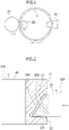
Fig. 1 is a plan view schematically showing an example of a ring-rolling device used in the ring-rolled member manufacturing method according to the present invention. -
Fig. 2 is a partially enlarged cross-sectional view schematically showing a main roll and a mandrel roll in the ring-rolling device inFig. 1 . -
Fig. 3 is a cross-sectional view showing in an enlarged manner a part showing an upper flange of the main roll inFig. 2 . -
Fig. 4 is a cross-sectional view showing, in an enlarged manner, a part showing a lower flange of the main roll inFig. 2 . -
Fig. 5 is a cross-sectional view schematically showing an example of a ring material used in the ring-rolled member manufacturing method according to the present invention. - Hereinafter, an embodiment of the ring-rolled member manufacturing method according to the present invention is explained with reference to the attached drawings. Note that the drawings put emphasis on clearly illustrating the embodiment of the present invention and are not necessarily drawn to scale.
- In the ring-rolled member manufacturing method according to the present embodiment, the ring-rolling device shown in
Fig. 1 to Fig. 4 is used, for example. The ring-rolling device is provided with amain roll 10 and amandrel roll 20 that are positioned respectively on an outer peripheral side and an inner peripheral side of aring material 1, which is a rolling target, having a ring-like shape. An outer peripheral face of themain roll 10 and an outer peripheral face of themandrel roll 20 face each other across thering material 1. Themain roll 10 is configured to be rotatable around acentral axis 10X thereof, and themandrel roll 20 is also configured to be rotatable around acentral axis 20X thereof. Thecentral axis 10X of themain roll 10 and thecentral axis 20X of themandrel roll 20 are substantially parallel. Themain roll 10 and themandrel roll 20 are configured to roll thering material 1 in a radial direction of the ring-like shape (hereinafter referred to as "ring radial direction") therebetween, and themandrel roll 20 is configured to be movable along the ring radial direction with respect to themain roll 10. Note that the central axis direction of the main roll and the central axis direction of the ring material correspond to each other. - In addition, the ring-rolling device is provided with a pair of
axial rolls 30 positioned to sandwich thering material 1 in the central axis direction of the ring-like shape (hereinafter referred to as "ring axis direction"). Note that, in the present specification, for the sake of simplicity of explanation, the upper side and the lower side inFig. 2 are referred to as "upper side" and "lower side", respectively, along thecentral axis 10X or thecentral axis 20X. Note that the pair ofaxial rolls 30 are positioned on the upper and lower sides of thering material 1. The pair ofaxial rolls 30 are configured to roll thering material 1 in the ring axis direction, and outer peripheral faces of the pair ofaxial rolls 30 face each other across thering material 1. The pair ofaxial rolls 30 are configured to be rotatable around the respective central axes thereof. - The outer peripheral face of the
main roll 10 includes a substantially U-shaped recessedportion 12 to accommodate thering material 1, which is the rolling target, and the outer peripheral face of themandrel roll 20, a first flange portion (hereinafter referred to as "upper flange portion") 11 positioned on one side in the central axis direction of the main roll, and a second flange portion (hereinafter referred to as "lower flange portion") 13 positioned on an opposite side of thefirst flange portion 11. In addition, an inner face of therecessed portion 12 of themain roll 10 includes a rollingface 12S to be in contact with the outer peripheral face of thering material 1, a first inner face (hereinafter referred to as "upper face") 11S on a side of theupper flange portion 11, and a second inner face (hereinafter referred to as "lower face") 13S on a side of thelower flange portion 13. - The rolling
face 12S of therecessed portion 12 of themain roll 10 is inclined to correspond to the outer peripheral face of the ring-rolled member after the rolling. In a similar manner, the outerperipheral face 20S of themandrel roll 20 is also inclined to correspond to the inner peripheral face of the ring-rolled member after the rolling. As shown inFig. 2 , a gap between therolling face 12S of therecessed portion 12 of themain roll 10 and the outerperipheral face 20S of themandrel roll 20 has a shape of the ring-rolled member after the rolling. As described above, the rollingface 12S of therecessed portion 12 of themain roll 10 and the outerperipheral face 20S of themandrel roll 20 correspond respectively to desired shapes of the outer peripheral face and the inner peripheral face of the ring-rolled member, and may be inclined in a linear shape, a curved shape, or a combination thereof. The thickness of the ring-rolled member is not required to be uniform, and therefore the inclinations of the outer peripheral face and the inner peripheral face of the ring-rolled member are not required to be at the same angle. - The
lower face 13S of therecessed portion 12 of themain roll 10 has, as shown inFig. 2 , a slope in such a way that the opening of therecessed portion 12 is enlarged toward the outer peripheral side of themain roll 10. Note that, inFig. 2 , since thelower face 13S is larger in area than theupper face 11S, thelower face 13S has the slope; however, depending on the desired shape of the ring-rolled member, in a case in which theupper face 11S is larger in area than thelower face 13S, theupper face 11S has a slope in such a way that the opening of therecessed portion 12 is enlarged toward the outer peripheral side. Alternatively, not only one of theupper face 11S and thelower face 13S, but both of theupper face 11S and thelower face 13S may have slopes. - The slope angle θa of the
upper face 11S is indicated by, as shown inFig. 3 , an angle between a perpendicular plane H perpendicularly intersecting the central axis direction of the main roll (typically a horizontal face in the ring radial direction) and theupper face 11S. The lower limit of the slope angle θa of theupper face 11S varies according to an inclination angle, which is described later, of the ring material, but is preferably greater than 0.3°, more preferably no less than 0.5°, still more preferably no less than 0.6°, and further more preferably no less than 1°. In addition, the upper limit of the slope angle θa of theupper face 11S is preferably no greater than 9°, more preferably less than 5°, still more preferably no greater than 3°, and further more preferably no greater than 2°. - In addition, the slope of the
upper face 11S is provided, as shown inFig. 3 , from a line of intersection V with the rollingface 12S of the recessedportion 12 of themain roll 10 to an end on the outer peripheral side (in other words, on an entire face of theupper face 11S); however, in order to produce the effects of the invention, it is only required to provide the slope, not from the line of intersection V with the rollingface 12S, but from a position Sa of the inner peripheral face of the desired ring-rolled member after rolling to the end on the outer peripheral side (in other words, a distance between the line of intersection V and the position Sa is a thickness Ra of an upper end portion of the desired ring-rolled member). In other words, a distance between the line of intersection V between theupper face 11S and the rollingface 12S and a terminal of the slope of theupper face 11S on the side of the rollingface 12S is less than the thickness Ra of the ring-rolled member. - The slope angle θb of the
lower face 13S is indicated by, as shown inFig. 4 , an angle between the perpendicular plane H perpendicularly intersecting the central axis direction of the main roll 10 (typically a horizontal face in the ring radial direction) and thelower face 13S. The lower limit of the slope angle θb of thelower face 13S varies according to an inclination angle, which is described later, of the ring material, but is preferably no less than 0.3°, more preferably no less than 0.5°, still more preferably no less than 0.6°, and further more preferably no less than 1°. The upper limit of the slope angle θb of thelower face 13 S varies according to an inclination angle, which is described later, of the ring material, but is preferably less than 9°, more preferably less than 5°, still more preferably less than 3°, and further more preferably less than 2°. - In addition, the slope of the
lower face 13S is provided, as shown inFig. 4 , from a line of intersection V with the rollingface 12S of the recessedportion 12 of themain roll 10 to an end on the outer peripheral side (in other words, on an entire face of thelower face 13S); however, in order to produce the effects of the invention, it is only required to provide the slope, not from the line of intersection V with the rollingface 12S, but from a position Sb of the inner peripheral face of the desired ring-rolled member after rolling to the end on the outer peripheral side (in other words, a distance between the line of intersection V and the position Sb is a thickness Rb of a lower end portion of the desired ring-rolled member). In other words, a distance between the line of intersection V between thelower face 13 S and the rollingface 12S and a terminal of the slope of thelower face 13S on the side of the rollingface 12S is less than the thickness Rb of the ring-rolled member. - In order to manufacture a ring-rolled member by using such a ring-rolling device, first, the
ring material 1 is loaded to the ring-rolling device. As thering material 1, a material formed from a heat-resistant alloy such as a Ni-based alloy, a Co-based alloy, and an Fe-based alloy is suitable. Since hot ductility of the heat-resistant alloy is significantly reduced due to a decrease in temperature, a temperature range in which the heat-resistant alloy can be plastically processed is extremely narrow. In other words, the heat-resistant alloy is rollable only for a short period of time. Therefore, the ring-rolling device according to the present embodiment enabling rolling in a stable attitude provides a profound effect. The heating temperature for thering material 1 loaded to the ring-rolling device varies according to the material of thering material 1. For example, in a case of thering material 1 being formed from Alloy 718, which is a Ni-based alloy, the heating temperature is preferably in a range from 1000 °C to 1050 °C; however, the heating temperature may vary according to a demand of a product and is not limited to this range. - In addition, the shape of the
ring material 1 to be loaded may be, for example, a so-called tapered ring with an outer peripheral face and an inner peripheral face being linearly inclined substantially uniformly, and a so-called odd-shaped ring being inclined in a curved shape or in a combination of a linear shape and a curved shape, or having a thickness which is partially different. The inclination angle θr of thering material 1 as described above is indicated by, even in the case in which the thickness of a part of the ring material is different as shown inFig. 5 , in the case of the tapered ring, an angle between a line D connecting an end face corner LD of a large-diameter outer periphery with an end face corner SD of a small-diameter outer periphery of thering material 1, and thecentral axis 1X of the ring shape of thering material 1. The lower limit of the inclination angle θr of thering material 1 is preferably no less than 5°, more preferably no less than 7°, still more preferably greater than 10°, and further more preferably no less than 15°. The upper limit of the inclination angle θr of thering material 1 is not particularly limited, and preferably no greater than 40°, more preferably no greater than 35°, and still more preferably no greater than 30°. Thering material 1 to be loaded may be, of course, a so-called rectangular ring without inclination. - Thereafter, the outer peripheral face of the
main roll 10 and the outer peripheral face of themandrel roll 20 are brought into contact with the outer peripheral face and the inner peripheral face of thering material 1, and the outer peripheral faces of the pair ofaxial rolls 30 are brought into contact with both of the upper and lower end faces of thering material 1 respectively. While themain roll 10 and themandrel roll 20 are rotated in the directions of the arrows shown inFig. 1 and Fig. 2 , themandrel roll 20 is moved toward themain roll 10, whereby themain roll 10 and themandrel roll 20 sandwich and compress thering material 1 in the ring radial direction. In addition, while the pair ofaxial rolls 30 are rotated in the direction of the arrow shown inFig. 1 , the pair ofaxial rolls 30 sandwich and compress thering material 1 in the ring axis direction. Thering material 1 is thus ring-rolled to yield a ring-rolled member. - In this case, even when the
ring material 1 is a tapered ring or an odd-shaped ring, since thelower face 13S of the recessedportion 12 of themain roll 10 has a slope in such a way that the opening of the recessedportion 12 is enlarged toward the outer peripheral side of themain roll 10 as shown inFig. 2 , the attitude of thering material 1 accommodated in the recessedportion 12 of themain roll 10 is stabilized by thelower face 13S and theupper face 11S of the recessedportion 12, whereby stable rotation of thering material 1 around thecentral axis 1X is enabled. This can suppress excessive contact of thering material 1 with theaxial roll 30 and the like, and in turn prevent generation of a defect. In particular, with thering material 1 in which the inclination angle θr is greater than 10°, stabilization of attitude during the ring-rolling is difficult due to a difference in peripheral speed between the die and the material, and therefore, the effect of the invention is remarkable. In addition, in a case in which the outer peripheral faces of themain roll 10 and themandrel roll 20 have predetermined shapes for obtaining an odd-shaped ring, stabilization of attitude during the ring-rolling is difficult due to a difference in an increase in diameter between a thick-walled portion and a thin-walled portion, and therefore, the effect of the invention is remarkable. - An Example of the present invention is described hereinafter. First, a test of providing an entire lower face of the recessed portion of the main roll of the ring-rolling device with a slope of a slope angle θb from 0° to 12° respectively, as shown in Table 1, and then ring-rolling the ring material was carried out. The test was carried out for two types of ring material: a tapered ring with an inclination angle of greater than 10°; and a tapered ring with an inclination angle of no greater than 10°. Then, stability of the ring material during the ring-rolling, and defects in a resulting ring-rolled member were evaluated. The results are also shown in Table 1.
- In addition, a test of providing an entire lower face of the recessed portion of the main roll of the ring-rolling device with a slope of a slope angle θb of 1.5°, providing an entire upper face of the recessed portion of the main roll with a slope of a slope angle θa from 0° to 12° respectively, as shown in Table 2, and then ring-rolling the ring material was carried out. In a similar manner to the foregoing, the test was carried out for two types of ring material: a tapered ring with an inclination angle of greater than 10°; and a tapered ring with an inclination angle of no greater than 10°. Then, stability of the ring material during the ring-rolling, and a defect in a resulting ring-rolled member were evaluated. The results are also shown in Table 2.
Table 1 Ring material with inclination angle no greater than 10° Ring material with inclination angle greater than 10° Slope angle θb of lower face Rolling stability Defects Slope angle θb of lower face Rolling stability Defect 0° Poor Poor 0° Poor Poor 0.1° Poor Fair 0.1° Poor Poor 0.3° Fair Good 0.3° Fair Fair 0.6° Excellent Excellent 0.6° Good Excellent 1° Excellent Excellent 1° Excellent Excellent 2° Good Good 2° Excellent Excellent 3° Fair Fair 3° Excellent Fair 5° Fair Fair 5° Good Fair 9° Fair Poor 9° Good Fair 12° Poor Poor 12° Poor Poor Table 2 Ring material with inclination angle no greater than 10° Ring material with inclination angle greater than 10° Slope angle θa of upper face Rolling stability Defects Slope angle θa of upper face Rolling stability Defect 0° Poor Poor 0° Poor Poor 0.1° Poor Good 0.1° Poor Poor 0.3° Fair Excellent 0.3° Poor Fair 0.6° Excellent Excellent 0.6° Good Excellent 1° Excellent Excellent 1° Excellent Excellent 2° Excellent Good 2° Excellent Excellent 3° Fair Fair 3° Excellent Fair 5° Fair Fair 5° Good Fair 9° Fair Poor 9° Good Fair 12° Poor Poor 12° Poor Poor - With regard to "Rolling Stability" in the Tables, behavior of the ring material during the ring-rolling was observed by shooting a video from an upper direction and a lateral direction of the ring material, and an evaluation of "Excellent" was given when abnormal behavior (slipping, heaving, vibrating) of the ring material was not observed during the ring-rolling, an evaluation of "Good" was given when a degree of the abnormal behavior was small, and an evaluation of "Poor" was given when a degree of the abnormal behavior was great (rolling to a desired diameter was not possible within a target period of time and rolling was stopped in the middle). An evaluation of "Fair" was given for a case between "Good" and "Poor".
- With regard to "Defects" in Tables, a defect in the resulting ring-rolled member was removed by a grinder, weight reduction after defect removal was measured, and an evaluation of "Excellent" was given when the weight loss was less than 0.1% with respect to the weight of the ring material, an evaluation of "Good" was given when the weight reduction was no less than 0.1% and less than 0.3%, an evaluation of "Fair" was given when the weight loss was no less than 0.3% and less than 1.5%, and an evaluation of "Poor" was given when the weight loss was no less than 1.5%.
- As shown in Table 1 and Table 2, when both of the lower face and the upper face of the recessed portion of the main roll had a very small slope angle of 0.1°, constriction of the ring material by the lower face and the upper face was too strong and caused resistance against rotation of the ring material, resulting in unstable rotation. In contrast, when the slope angle was far too greater of 10°, retention of the ring material was insufficient and the ring material had a tilted attitude, resulting in an increase in instability of rotation due to friction with the main roll.
- In addition, when the ring material having a great inclination angle was loaded, an attitude of the ring material was tilted during the ring-rolling due to a difference in peripheral speed between the main roll and the ring material; however, when the slope angle was in such a range that the tilt of the ring material is not constrained, stability of rotation of the ring material was achieved. The rolling stability and generation of a defect showed the same trend to a certain degree.
- Specifically, from the results shown in Table 1 and Table 2, it is observed that, regardless of the inclination angle of the ring material, when both of the lower face and the upper face formed on the main roll had the slope angle in a range of no less than 0.5° and less than 3°, the rolling stability was superior and the number of defects was small. In particular, in the case in which the inclination angle of the ring material was no greater than 10°, the rolling stability was superior when the slope angle was in a range of greater than 0.3° and less than 3°, and both of the rolling stability and defect prevention were remarkably superior when the slope angle was in a range of no less than 0.5° and less than 2°. In addition, in the case in which the inclination angle of the ring material was greater than 10°, the rolling stability was superior when the slope angle was in a range of no less than 0.6° and no greater than 9°, and both of the rolling stability and defect prevention were remarkably superior when the slope angle was in a range of no less than 1° and less than 3°.
-
- 1:
- Ring material
- 10:
- Main roll
- 11:
- First flange portion (Upper flange portion)
- 11S:
- First inner face (Upper face)
- 12:
- Recessed portion
- 12S:
- Rolling face
- 13:
- Second flange portion (Lower flange portion)
- 13S:
- Second inner face (Lower face)
- 20:
- Mandrel roll
- 30:
- Axial roll
Claims (5)
- A method of manufacturing a ring-rolled member by ring-rolling a ring material with a ring-rolling device, the ring-rolling device comprising a main roll and a mandrel roll, wherein an outer peripheral face of the main roll includes a recessed portion to accommodate the ring material and an outer peripheral face of the mandrel roll, a first flange portion positioned on one side in a central axis direction of the main roll with respect to the recessed portion, and a second flange portion positioned on an opposite side of the first flange portion; an inner face of the recessed portion includes a rolling face to be in contact with an outer peripheral face of the ring material, a first inner face on a side of the first flange portion, and a second inner face on a side of the second flange portion; at least one inner face among the first inner face and the second inner face has a slope in such a way that an opening of the recessed portion is enlarged, with reference to a perpendicular plane perpendicularly intersecting the central axis direction of the main roll; the slope starts from within a range of a distance corresponding to a thickness of the ring-rolled member from a line of intersection between the at least one inner face and the rolling face; and an angle of the slope is greater than 0.3° and no greater than 9° with reference to the perpendicular plane.
- The ring-rolled member manufacturing method according to claim 1, wherein the ring material is a heat-resistant alloy, which is a Ni-based alloy, a Co-based alloy, or an Fe-based alloy.
- The ring-rolled member manufacturing method according to claim 1 or 2, wherein the outer peripheral face of the ring material is at least partially inclined with respect to a central axis of the ring material; and an angle between a straight line connecting an end face corner of a large-diameter outer periphery with an end face corner of a small-diameter outer periphery of the ring material and the central axis of the ring material is greater than 10°.
- The ring-rolled member manufacturing method according to claim 3, wherein the angle of the slope of the inner face is no less than 0.6° and no greater than 9° with reference to the perpendicular plane.
- The ring-rolled member manufacturing method according to claim 1 or 2, wherein the outer peripheral face of the ring material is at least partially inclined with respect to a central axis of the ring material; and, when an angle between a straight line D connecting an end face corner LD of a large-diameter outer periphery with an end face corner SD of a small-diameter outer periphery of the ring material and the central axis of the ring material is no greater than 10°, the angle of the slope of the inner face is greater than 0.3° and less than 3° with reference to the perpendicular plane.
Applications Claiming Priority (2)
| Application Number | Priority Date | Filing Date | Title |
|---|---|---|---|
| JP2019234875A JP7121929B2 (en) | 2019-12-25 | 2019-12-25 | Method for manufacturing ring rolled material |
| PCT/JP2020/046953 WO2021131963A1 (en) | 2019-12-25 | 2020-12-16 | Method of manufacturing ring-rolled element |
Publications (3)
| Publication Number | Publication Date |
|---|---|
| EP4082684A1 true EP4082684A1 (en) | 2022-11-02 |
| EP4082684A4 EP4082684A4 (en) | 2023-06-14 |
| EP4082684B1 EP4082684B1 (en) | 2025-10-22 |
Family
ID=76575911
Family Applications (1)
| Application Number | Title | Priority Date | Filing Date |
|---|---|---|---|
| EP20908430.0A Active EP4082684B1 (en) | 2019-12-25 | 2020-12-16 | Method of manufacturing ring-rolled element |
Country Status (6)
| Country | Link |
|---|---|
| US (1) | US12168253B2 (en) |
| EP (1) | EP4082684B1 (en) |
| JP (1) | JP7121929B2 (en) |
| CN (2) | CN114845821A (en) |
| MX (1) | MX2022007170A (en) |
| WO (1) | WO2021131963A1 (en) |
Family Cites Families (18)
| Publication number | Priority date | Publication date | Assignee | Title |
|---|---|---|---|---|
| US1971027A (en) * | 1932-02-29 | 1934-08-21 | Edgewater Steel | Process of rolling rings |
| CN1253259C (en) * | 2004-09-21 | 2006-04-26 | 武汉理工大学 | Process for rolling and forming external step section ring piece |
| CN100506422C (en) * | 2007-06-14 | 2009-07-01 | 兰鹏光 | Forging and Rolling Forming Method of Wind Power Tower Flange |
| CN101279347A (en) | 2008-04-23 | 2008-10-08 | 贵州航宇科技发展有限公司 | Method for rolling and shaping stainless steel conical ring |
| CN100574925C (en) * | 2008-04-23 | 2009-12-30 | 贵州航宇科技发展有限公司 | Rolling forming method of titanium alloy conical ring forging |
| CN101279349A (en) | 2008-04-23 | 2008-10-08 | 贵州航宇科技发展有限公司 | Rolling forming method of nickel-base superalloy tapered ring forgings |
| CN101279346B (en) * | 2008-04-23 | 2010-07-14 | 贵州安大航空锻造有限责任公司 | Rolling forming method of special-shaped ring forgings of nickel-base superalloy |
| CN100569412C (en) * | 2008-04-23 | 2009-12-16 | 贵州航宇科技发展有限公司 | Rolling forming method of aluminum alloy tapered ring forging |
| JP5795838B2 (en) | 2009-09-10 | 2015-10-14 | 日立金属Mmcスーパーアロイ株式会社 | Method for producing ring-shaped molded body |
| JP2013169563A (en) * | 2012-02-20 | 2013-09-02 | Sanyo Special Steel Co Ltd | Ring rolling method |
| JP6292761B2 (en) | 2013-03-28 | 2018-03-14 | 日立金属Mmcスーパーアロイ株式会社 | Method for producing annular molded body |
| CN107255053B (en) | 2013-06-07 | 2019-11-05 | 株式会社理研 | Piston ring raw material |
| CN107206469B (en) * | 2014-09-01 | 2019-04-02 | 日立金属株式会社 | Manufacturing method of annular shaped body |
| CN205183628U (en) | 2015-09-02 | 2016-04-27 | 中航卓越锻造(无锡)有限公司 | Oblique boss annular forging of inside and outside dysmorphism and mould thereof |
| CN107127279A (en) | 2016-02-26 | 2017-09-05 | 陕西宏远航空锻造有限责任公司 | A kind of enclosed milling method of highly different ring |
| CN106903244B (en) * | 2017-04-21 | 2018-07-24 | 桂林电子科技大学 | A kind of hot rolling forming method of centrifugal casting bi-metal double abnormity ring |
| CN208083300U (en) | 2018-04-18 | 2018-11-13 | 苏州市木冶机械锻造有限公司 | A kind of ring rolls valve cover die |
| CN108907045B (en) * | 2018-09-21 | 2024-03-26 | 济南沃茨数控机械有限公司 | Roller axial adjusting mechanism and ring rolling machine |
-
2019
- 2019-12-25 JP JP2019234875A patent/JP7121929B2/en active Active
-
2020
- 2020-12-16 CN CN202080089438.5A patent/CN114845821A/en active Pending
- 2020-12-16 MX MX2022007170A patent/MX2022007170A/en unknown
- 2020-12-16 WO PCT/JP2020/046953 patent/WO2021131963A1/en not_active Ceased
- 2020-12-16 EP EP20908430.0A patent/EP4082684B1/en active Active
- 2020-12-16 US US17/787,865 patent/US12168253B2/en active Active
- 2020-12-16 CN CN202511416419.XA patent/CN121103976A/en active Pending
Also Published As
| Publication number | Publication date |
|---|---|
| MX2022007170A (en) | 2022-07-12 |
| US20230043008A1 (en) | 2023-02-09 |
| JP2021102222A (en) | 2021-07-15 |
| JP7121929B2 (en) | 2022-08-19 |
| US12168253B2 (en) | 2024-12-17 |
| WO2021131963A1 (en) | 2021-07-01 |
| EP4082684B1 (en) | 2025-10-22 |
| CN121103976A (en) | 2025-12-12 |
| EP4082684A4 (en) | 2023-06-14 |
| CN114845821A (en) | 2022-08-02 |
Similar Documents
| Publication | Publication Date | Title |
|---|---|---|
| EP2979774B1 (en) | Method for manufacturing annular formed body | |
| JP6650110B2 (en) | Ring rolling mill and method for producing rolled material | |
| EP2796264A1 (en) | Tire mold | |
| US20140157851A1 (en) | Method of manufacturing annular molding | |
| WO2015137340A1 (en) | Crucible and single crystal sapphire production method using same | |
| JP5855529B2 (en) | Hot rolling method for ring material | |
| US11208910B2 (en) | Ring molded article manufacturing method and ring material | |
| EP4082684B1 (en) | Method of manufacturing ring-rolled element | |
| EP2692453B1 (en) | Method for manufacturing roll for reducing, and roll for reducing | |
| KR20180027623A (en) | A frictionless forged aluminum alloy sputtering target with improved properties | |
| EP2839890A1 (en) | Round billet for seamless metal tube and method for producing seamless metal tube | |
| JP2009006336A (en) | Hot rolling method using cemented carbide work rolls | |
| JP5765757B2 (en) | Method for manufacturing annular shaped material | |
| JPWO1996021526A1 (en) | Piercing and rolling method for seamless metal pipes and apparatus therefor | |
| JP5163417B2 (en) | Rolling method for section steel with flange | |
| JPH0696161B2 (en) | Roll for reducing web thickness of profile | |
| JPS62263805A (en) | Structure of rolling roll | |
| JP2695029B2 (en) | Shaped steel edger rolling machine | |
| JP3484334B2 (en) | Cold rolling method | |
| JP3266062B2 (en) | Method and apparatus for manufacturing metal material having circular cross section | |
| JP2003039102A (en) | Precision rolling method for steel bars and wire rods | |
| KR20230093822A (en) | The device and method for manufacturing the slab | |
| JPS613601A (en) | Production of metallic material having circular section | |
| JP2022091249A (en) | Disk blank manufacturing method | |
| JPH0679301A (en) | Flexible rolling method of shaped steel with flange |
Legal Events
| Date | Code | Title | Description |
|---|---|---|---|
| STAA | Information on the status of an ep patent application or granted ep patent |
Free format text: STATUS: THE INTERNATIONAL PUBLICATION HAS BEEN MADE |
|
| PUAI | Public reference made under article 153(3) epc to a published international application that has entered the european phase |
Free format text: ORIGINAL CODE: 0009012 |
|
| STAA | Information on the status of an ep patent application or granted ep patent |
Free format text: STATUS: REQUEST FOR EXAMINATION WAS MADE |
|
| 17P | Request for examination filed |
Effective date: 20220621 |
|
| AK | Designated contracting states |
Kind code of ref document: A1 Designated state(s): AL AT BE BG CH CY CZ DE DK EE ES FI FR GB GR HR HU IE IS IT LI LT LU LV MC MK MT NL NO PL PT RO RS SE SI SK SM TR |
|
| DAV | Request for validation of the european patent (deleted) | ||
| DAX | Request for extension of the european patent (deleted) | ||
| RAP3 | Party data changed (applicant data changed or rights of an application transferred) |
Owner name: PROTERIAL, LTD. |
|
| REG | Reference to a national code |
Ref country code: DE Ipc: B21H0001060000 Ref country code: DE Ref legal event code: R079 Ref document number: 602020061021 Country of ref document: DE Free format text: PREVIOUS MAIN CLASS: B21B0005000000 Ipc: B21H0001060000 |
|
| A4 | Supplementary search report drawn up and despatched |
Effective date: 20230515 |
|
| RIC1 | Information provided on ipc code assigned before grant |
Ipc: B21H 1/06 20060101AFI20230509BHEP |
|
| RIC1 | Information provided on ipc code assigned before grant |
Ipc: B21H 1/06 20060101AFI20250423BHEP |
|
| GRAP | Despatch of communication of intention to grant a patent |
Free format text: ORIGINAL CODE: EPIDOSNIGR1 |
|
| STAA | Information on the status of an ep patent application or granted ep patent |
Free format text: STATUS: GRANT OF PATENT IS INTENDED |
|
| INTG | Intention to grant announced |
Effective date: 20250602 |
|
| GRAS | Grant fee paid |
Free format text: ORIGINAL CODE: EPIDOSNIGR3 |
|
| GRAA | (expected) grant |
Free format text: ORIGINAL CODE: 0009210 |
|
| STAA | Information on the status of an ep patent application or granted ep patent |
Free format text: STATUS: THE PATENT HAS BEEN GRANTED |
|
| AK | Designated contracting states |
Kind code of ref document: B1 Designated state(s): AL AT BE BG CH CY CZ DE DK EE ES FI FR GB GR HR HU IE IS IT LI LT LU LV MC MK MT NL NO PL PT RO RS SE SI SK SM TR |
|
| REG | Reference to a national code |
Ref country code: CH Ref legal event code: F10 Free format text: ST27 STATUS EVENT CODE: U-0-0-F10-F00 (AS PROVIDED BY THE NATIONAL OFFICE) Effective date: 20251022 Ref country code: GB Ref legal event code: FG4D |
|
| REG | Reference to a national code |
Ref country code: DE Ref legal event code: R096 Ref document number: 602020061021 Country of ref document: DE |
|
| REG | Reference to a national code |
Ref country code: IE Ref legal event code: FG4D |
|
| PGFP | Annual fee paid to national office [announced via postgrant information from national office to epo] |
Ref country code: GB Payment date: 20251216 Year of fee payment: 6 |
|
| PGFP | Annual fee paid to national office [announced via postgrant information from national office to epo] |
Ref country code: IT Payment date: 20251210 Year of fee payment: 6 |
|
| PGFP | Annual fee paid to national office [announced via postgrant information from national office to epo] |
Ref country code: FR Payment date: 20251205 Year of fee payment: 6 |
|
| P01 | Opt-out of the competence of the unified patent court (upc) registered |
Free format text: CASE NUMBER: UPC_APP_0018424_4082684/2025 Effective date: 20251219 |
|
| REG | Reference to a national code |
Ref country code: NL Ref legal event code: MP Effective date: 20251022 |
|
| PG25 | Lapsed in a contracting state [announced via postgrant information from national office to epo] |
Ref country code: NL Free format text: LAPSE BECAUSE OF FAILURE TO SUBMIT A TRANSLATION OF THE DESCRIPTION OR TO PAY THE FEE WITHIN THE PRESCRIBED TIME-LIMIT Effective date: 20251022 |
|
| PG25 | Lapsed in a contracting state [announced via postgrant information from national office to epo] |
Ref country code: ES Free format text: LAPSE BECAUSE OF FAILURE TO SUBMIT A TRANSLATION OF THE DESCRIPTION OR TO PAY THE FEE WITHIN THE PRESCRIBED TIME-LIMIT Effective date: 20251022 |
|
| REG | Reference to a national code |
Ref country code: LT Ref legal event code: MG9D |
|
| PG25 | Lapsed in a contracting state [announced via postgrant information from national office to epo] |
Ref country code: NO Free format text: LAPSE BECAUSE OF FAILURE TO SUBMIT A TRANSLATION OF THE DESCRIPTION OR TO PAY THE FEE WITHIN THE PRESCRIBED TIME-LIMIT Effective date: 20260122 |
|
| PGFP | Annual fee paid to national office [announced via postgrant information from national office to epo] |
Ref country code: DE Payment date: 20251217 Year of fee payment: 6 |
|
| PG25 | Lapsed in a contracting state [announced via postgrant information from national office to epo] |
Ref country code: HR Free format text: LAPSE BECAUSE OF FAILURE TO SUBMIT A TRANSLATION OF THE DESCRIPTION OR TO PAY THE FEE WITHIN THE PRESCRIBED TIME-LIMIT Effective date: 20251022 Ref country code: AT Free format text: LAPSE BECAUSE OF FAILURE TO SUBMIT A TRANSLATION OF THE DESCRIPTION OR TO PAY THE FEE WITHIN THE PRESCRIBED TIME-LIMIT Effective date: 20251022 Ref country code: FI Free format text: LAPSE BECAUSE OF FAILURE TO SUBMIT A TRANSLATION OF THE DESCRIPTION OR TO PAY THE FEE WITHIN THE PRESCRIBED TIME-LIMIT Effective date: 20251022 |
|
| REG | Reference to a national code |
Ref country code: AT Ref legal event code: MK05 Ref document number: 1848740 Country of ref document: AT Kind code of ref document: T Effective date: 20251022 |
|
| PG25 | Lapsed in a contracting state [announced via postgrant information from national office to epo] |
Ref country code: RS Free format text: LAPSE BECAUSE OF FAILURE TO SUBMIT A TRANSLATION OF THE DESCRIPTION OR TO PAY THE FEE WITHIN THE PRESCRIBED TIME-LIMIT Effective date: 20260122 |
|
| PG25 | Lapsed in a contracting state [announced via postgrant information from national office to epo] |
Ref country code: IS Free format text: LAPSE BECAUSE OF FAILURE TO SUBMIT A TRANSLATION OF THE DESCRIPTION OR TO PAY THE FEE WITHIN THE PRESCRIBED TIME-LIMIT Effective date: 20260222 |
|
| PG25 | Lapsed in a contracting state [announced via postgrant information from national office to epo] |
Ref country code: PT Free format text: LAPSE BECAUSE OF FAILURE TO SUBMIT A TRANSLATION OF THE DESCRIPTION OR TO PAY THE FEE WITHIN THE PRESCRIBED TIME-LIMIT Effective date: 20260223 |
|
| PG25 | Lapsed in a contracting state [announced via postgrant information from national office to epo] |
Ref country code: PL Free format text: LAPSE BECAUSE OF FAILURE TO SUBMIT A TRANSLATION OF THE DESCRIPTION OR TO PAY THE FEE WITHIN THE PRESCRIBED TIME-LIMIT Effective date: 20251022 |
|
| PG25 | Lapsed in a contracting state [announced via postgrant information from national office to epo] |
Ref country code: LV Free format text: LAPSE BECAUSE OF FAILURE TO SUBMIT A TRANSLATION OF THE DESCRIPTION OR TO PAY THE FEE WITHIN THE PRESCRIBED TIME-LIMIT Effective date: 20251022 |
|
| PG25 | Lapsed in a contracting state [announced via postgrant information from national office to epo] |
Ref country code: BG Free format text: LAPSE BECAUSE OF FAILURE TO SUBMIT A TRANSLATION OF THE DESCRIPTION OR TO PAY THE FEE WITHIN THE PRESCRIBED TIME-LIMIT Effective date: 20251022 |
|
| PG25 | Lapsed in a contracting state [announced via postgrant information from national office to epo] |
Ref country code: RO Free format text: LAPSE BECAUSE OF FAILURE TO SUBMIT A TRANSLATION OF THE DESCRIPTION OR TO PAY THE FEE WITHIN THE PRESCRIBED TIME-LIMIT Effective date: 20251022 |
|
| PG25 | Lapsed in a contracting state [announced via postgrant information from national office to epo] |
Ref country code: LT Free format text: LAPSE BECAUSE OF FAILURE TO SUBMIT A TRANSLATION OF THE DESCRIPTION OR TO PAY THE FEE WITHIN THE PRESCRIBED TIME-LIMIT Effective date: 20251022 |
|
| PG25 | Lapsed in a contracting state [announced via postgrant information from national office to epo] |
Ref country code: SM Free format text: LAPSE BECAUSE OF FAILURE TO SUBMIT A TRANSLATION OF THE DESCRIPTION OR TO PAY THE FEE WITHIN THE PRESCRIBED TIME-LIMIT Effective date: 20251022 |
|
| PG25 | Lapsed in a contracting state [announced via postgrant information from national office to epo] |
Ref country code: MC Free format text: LAPSE BECAUSE OF FAILURE TO SUBMIT A TRANSLATION OF THE DESCRIPTION OR TO PAY THE FEE WITHIN THE PRESCRIBED TIME-LIMIT Effective date: 20251022 |
|
| PG25 | Lapsed in a contracting state [announced via postgrant information from national office to epo] |
Ref country code: DK Free format text: LAPSE BECAUSE OF FAILURE TO SUBMIT A TRANSLATION OF THE DESCRIPTION OR TO PAY THE FEE WITHIN THE PRESCRIBED TIME-LIMIT Effective date: 20251022 |
|
| PG25 | Lapsed in a contracting state [announced via postgrant information from national office to epo] |
Ref country code: EE Free format text: LAPSE BECAUSE OF FAILURE TO SUBMIT A TRANSLATION OF THE DESCRIPTION OR TO PAY THE FEE WITHIN THE PRESCRIBED TIME-LIMIT Effective date: 20251022 |
|
| PG25 | Lapsed in a contracting state [announced via postgrant information from national office to epo] |
Ref country code: CZ Free format text: LAPSE BECAUSE OF FAILURE TO SUBMIT A TRANSLATION OF THE DESCRIPTION OR TO PAY THE FEE WITHIN THE PRESCRIBED TIME-LIMIT Effective date: 20251022 |
|
| REG | Reference to a national code |
Ref country code: CH Ref legal event code: H13 Free format text: ST27 STATUS EVENT CODE: U-0-0-H10-H13 (AS PROVIDED BY THE NATIONAL OFFICE) Effective date: 20260723 |
|
| PG25 | Lapsed in a contracting state [announced via postgrant information from national office to epo] |
Ref country code: SK Free format text: LAPSE BECAUSE OF FAILURE TO SUBMIT A TRANSLATION OF THE DESCRIPTION OR TO PAY THE FEE WITHIN THE PRESCRIBED TIME-LIMIT Effective date: 20251022 |
|
| PG25 | Lapsed in a contracting state [announced via postgrant information from national office to epo] |
Ref country code: SE Free format text: LAPSE BECAUSE OF FAILURE TO SUBMIT A TRANSLATION OF THE DESCRIPTION OR TO PAY THE FEE WITHIN THE PRESCRIBED TIME-LIMIT Effective date: 20251022 |