EP4080730A1 - Magnetic pole-piece device and magnetic gear - Google Patents
Magnetic pole-piece device and magnetic gear Download PDFInfo
- Publication number
- EP4080730A1 EP4080730A1 EP21744522.0A EP21744522A EP4080730A1 EP 4080730 A1 EP4080730 A1 EP 4080730A1 EP 21744522 A EP21744522 A EP 21744522A EP 4080730 A1 EP4080730 A1 EP 4080730A1
- Authority
- EP
- European Patent Office
- Prior art keywords
- magnetic pole
- electrical steel
- pole piece
- magnetic
- steel sheet
- Prior art date
- Legal status (The legal status is an assumption and is not a legal conclusion. Google has not performed a legal analysis and makes no representation as to the accuracy of the status listed.)
- Pending
Links
Images


Classifications
-
- H—ELECTRICITY
- H02—GENERATION; CONVERSION OR DISTRIBUTION OF ELECTRIC POWER
- H02K—DYNAMO-ELECTRIC MACHINES
- H02K49/00—Dynamo-electric clutches; Dynamo-electric brakes
- H02K49/10—Dynamo-electric clutches; Dynamo-electric brakes of the permanent-magnet type
- H02K49/102—Magnetic gearings, i.e. assembly of gears, linear or rotary, by which motion is magnetically transferred without physical contact
-
- H—ELECTRICITY
- H02—GENERATION; CONVERSION OR DISTRIBUTION OF ELECTRIC POWER
- H02K—DYNAMO-ELECTRIC MACHINES
- H02K1/00—Details of the magnetic circuit
- H02K1/06—Details of the magnetic circuit characterised by the shape, form or construction
-
- H—ELECTRICITY
- H02—GENERATION; CONVERSION OR DISTRIBUTION OF ELECTRIC POWER
- H02K—DYNAMO-ELECTRIC MACHINES
- H02K16/00—Machines with more than one rotor or stator
- H02K16/02—Machines with one stator and two or more rotors
-
- H—ELECTRICITY
- H02—GENERATION; CONVERSION OR DISTRIBUTION OF ELECTRIC POWER
- H02K—DYNAMO-ELECTRIC MACHINES
- H02K49/00—Dynamo-electric clutches; Dynamo-electric brakes
- H02K49/10—Dynamo-electric clutches; Dynamo-electric brakes of the permanent-magnet type
- H02K49/104—Magnetic couplings consisting of only two coaxial rotary elements, i.e. the driving element and the driven element
- H02K49/106—Magnetic couplings consisting of only two coaxial rotary elements, i.e. the driving element and the driven element with a radial air gap
-
- H—ELECTRICITY
- H02—GENERATION; CONVERSION OR DISTRIBUTION OF ELECTRIC POWER
- H02K—DYNAMO-ELECTRIC MACHINES
- H02K9/00—Arrangements for cooling or ventilating
- H02K9/22—Arrangements for cooling or ventilating by solid heat conducting material embedded in, or arranged in contact with, the stator or rotor, e.g. heat bridges
- H02K9/223—Heat bridges
-
- H—ELECTRICITY
- H02—GENERATION; CONVERSION OR DISTRIBUTION OF ELECTRIC POWER
- H02K—DYNAMO-ELECTRIC MACHINES
- H02K2201/00—Specific aspects not provided for in the other groups of this subclass relating to the magnetic circuits
- H02K2201/06—Magnetic cores, or permanent magnets characterised by their skew
-
- H—ELECTRICITY
- H02—GENERATION; CONVERSION OR DISTRIBUTION OF ELECTRIC POWER
- H02K—DYNAMO-ELECTRIC MACHINES
- H02K2213/00—Specific aspects, not otherwise provided for and not covered by codes H02K2201/00 - H02K2211/00
- H02K2213/03—Machines characterised by numerical values, ranges, mathematical expressions or similar information
Definitions
- the present disclosure relates to a magnetic pole piece device and a magnetic gear including the magnetic pole piece device.
- a flux-modulated type (harmonic type) magnetic gear of the magnetic gear includes an inner circumferential side magnet field and an outer circumferential side magnet field concentrically (coaxially) disposed, and a magnetic pole piece device which has a plurality of magnetic pole pieces (pole pieces) and a plurality of non-magnetic materials each being disposed with a gap (air gap) between these two magnet fields and alternately arranged in the circumferential direction (see Patent Documents 1 and 2).
- magnetic fluxes of magnets of the above-described two magnet fields are modulated by the above-described respective magnetic pole pieces to generate harmonic magnetic fluxes, and the above-described two magnet fields are synchronized with the harmonic magnetic fluxes, respectively, thereby operating the flux-modulated type magnetic gear.
- the above-described outer circumferential side magnet field is fixed to function as a stator, as well as the above-described inner circumferential side magnet field is functioned as a high-speed rotor and the above-described magnetic pole piece device is functioned as a low-speed rotor. Then, by rotating the high-speed rotor by a magnetomotive force of a coil, the low-speed rotor rotates according to the reduction ratio which is determined by the ratio of the number of pole pairs of the high-speed rotor and the number of pole pairs of the low-speed rotor.
- the magnetic geared motor for example, a type in which a permanent magnet is installed in a high-speed rotor and a stator, or a type in which a permanent magnet is installed only in a high-speed rotor is known.
- a plurality of magnetic pole pieces of the above-described magnetic pole piece device are usually formed by laminating steel sheets (electrical steel sheets) in a direction (axial direction) along a rotational axis of the magnetic pole piece device.
- the problem arises in that efficiency is decreased when an iron loss (eddy current loss) is caused due to an axial leakage magnetic flux at an end of the magnetic pole piece.
- an object of at least one embodiment of the present invention is to provide a magnetic pole piece device seeking to suppress the axial leakage magnetic flux at the end of the magnetic pole piece.
- a magnetic pole piece device is a magnetic pole piece device disposed between an inner diameter side magnet field and an outer diameter side magnet field of a magnetic gear, that includes a plurality of magnetic pole pieces disposed at intervals in a circumferential direction of the magnetic gear.
- Each of the plurality of magnetic pole pieces includes a plurality of plate-shaped electrical steel sheets having a longitudinal direction. The plurality of electrical steel sheets are laminated along the circumferential direction, with the longitudinal direction being along an axial direction of the magnetic gear.
- a magnetic gear includes: an inner diameter side magnet field; an outer diameter side magnet field disposed on an outer diameter side relative to the inner diameter side magnet field; and the above-described magnetic pole piece device disposed between the inner diameter side magnet field and the outer diameter side magnet field.
- a magnetic pole piece device which seeks to suppress an iron loss (eddy current loss) due to an axial leakage magnetic flux at an end of a magnetic pole piece.
- an expression of relative or absolute arrangement such as “in a direction”, “along a direction”, “parallel”, “orthogonal”, “centered”, “concentric” and “coaxial” shall not be construed as indicating only the arrangement in a strict literal sense, but also includes a state where the arrangement is relatively displaced by a tolerance, or by an angle or a distance whereby it is possible to achieve the same function.
- an expression of an equal state such as “same”, “equal”, and “uniform” shall not be construed as indicating only the state in which the feature is strictly equal, but also includes a state in which there is a tolerance or a difference that can still achieve the same function.
- an expression of a shape such as a rectangular shape or a tubular shape shall not be construed as only the geometrically strict shape, but also includes a shape with unevenness or chamfered corners within the range in which the same effect can be achieved.
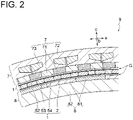
- FIG. 1 is a schematic view showing a cross section of a magnetic gear 9 orthogonal to an axial direction b according to an embodiment of the present invention. Further, FIG. 2 is a partially enlarged view of the cross section of the magnetic gear shown in FIG. 1 .
- FIGs. 3 , 4A , and 5 to 14 are each a schematic view of a magnetic pole piece 2 according to an embodiment of the present invention.
- a direction along a rotation direction of the magnetic gear 9 (magnetic pole piece device 1) being a circumferential direction a
- a direction along a rotational axis (axis 1) of the magnetic gear 9 (magnetic pole piece device 1) being the axial direction b
- a direction (radial direction) orthogonal to the circumferential direction a and the axial direction b described above being a radial direction c.
- the magnetic gear 9 is a device having a mechanism for transmitting torque in a non-contact manner by utilizing an attractive force and a repulsive force of a magnet.
- the magnetic gear 9 shown in FIGs. 1 and 2 is of a flux-modulated type (harmonic type) and as illustrated, includes an outer diameter side magnet field 7 (outer rotor) having a cylindrical shape (annular; the same applies hereinafter) as a whole, an inner diameter side magnet field 8 (inner rotor) having a cylindrical or columnar shape as a whole, and a magnetic pole piece device 1 (center rotor) having a cylindrical shape as a whole.
- the magnetic gear 9 has a structure where the outer diameter side magnet field 7, the inner diameter side magnet field 8, and the magnetic pole piece device 1 are disposed at intervals (air gaps G) of a constant distance from each other in the radial direction c on the same axis 1 (coaxial) when the magnetic pole piece device 1 is disposed between the outer diameter side magnet field 7 and the inner diameter side magnet field 8. That is, the outer diameter side magnet field 7 is disposed on the radially outer side (outer diameter side) relative to the inner diameter side magnet field 8. Further, the magnetic pole piece device 1 is disposed between the inner diameter side magnet field 8 and the outer diameter side magnet field 7. Then, the outer diameter side magnet field 7, the inner diameter side magnet field 8, and the magnetic pole piece device 1 are disposed concentrically.
- the outer diameter side magnet field 7 and the inner diameter side magnet field 8 described above, respectively, include magnetic pole pairs (71, 81) of a permanent magnet or the like which are composed of a plurality of N poles and S poles disposed at intervals (regular intervals) on the circumference in a cross section of the magnetic geared 9 cut along the radial direction c.
- the outer diameter side magnet field 7 includes the plurality of magnetic pole pairs 71 and a support member 72 for supporting the plurality of magnetic pole pairs 71.
- the plurality of magnetic pole pairs 71 are installed over the whole circumference in a state where the magnetic poles face the radial direction c and such that the N poles and the S poles are alternated along the circumferential direction.
- the above-described inner diameter side magnet field 8 includes the plurality of magnetic pole pairs 81 and a columnar support member 82 for supporting the plurality of magnetic pole pairs 81.
- the plurality of magnetic pole pairs 81 are installed over the whole circumference along the circumferential direction a in the same manner as above.
- the magnetic pole piece device 1 includes a plurality of magnetic pole pieces 2 (pole pieces) disposed at intervals (regular intervals) from each other over the whole circumference in the circumferential direction a. Then, for example, if the inner diameter side magnet field 8 is rotated, the magnetic flux of the inner diameter side magnet field 8 is modulated by the magnetic pole pieces of the magnetic pole piece device 1, and rotational torque is generated in the magnetic pole piece device 1 by the action of the modulated magnetic field and the outer diameter side magnet field 7.
- the above-described magnetic pole piece device 1 may include an outer circumferential cover member 52 and an inner circumferential cover member 53 disposed on the outer side and the inner side in the radial direction c so as to sandwich the above-described plurality of magnetic pole pieces 2.
- the outer circumferential cover member 52 and the inner circumferential cover member 53 are members each having a cylindrical shape, and the diameter of the inner circumferential cover member 53 is smaller than the diameter of the outer circumferential cover member 52.
- the inner circumferential cover member 53 is disposed coaxially on the inner side of the outer circumferential cover member 52, a cylindrical space is formed over the entire circumference between the inner circumferential surface of the outer circumferential cover member 52 and the outer circumferential surface of the inner circumferential cover member 53.
- the plurality of long magnetic pole pieces 2 are disposed at intervals in the circumferential direction a with a longitudinal direction of each of the magnetic pole pieces 2 oriented along the axial direction b.
- a section (interjacent space 54) between the plurality of magnetic pole pieces 2 may be a space, or a non-magnetic material may be installed in the section.
- the magnetic pole piece device 1 may not have the above-described two cover members, or may be configured to include the non-magnetic material installed between the plurality of magnetic pole pieces 2.
- the magnetic gear 9 (flux-modulated type magnetic gear) is integrated with a motor to form a magnetic geared motor.
- a plurality of coils 73 are installed in the outer diameter side magnet field 7 to each be used as a stator, and the inner diameter side magnet field 8 (high-speed rotor) is rotated by a magnetomotive force of the coils 73.
- the magnetic pole piece device 1 (low-speed rotor) rotates according to the reduction ratio which is determined by the ratio of the number of pole pairs of the magnetic pole pairs 71 of the outer diameter side magnet field 7 to the number of pole pairs of the magnetic pole pairs 81 of the inner diameter side magnet field 8.
- the magnetic geared motor is supplied with a cooling medium, such as air or water, in order to protect the above-described constituent elements from heat generated during operation.
- a cooling medium such as air or water
- the cooling medium is supplied to the above-described air gaps G, which are respectively formed on the inner circumferential side and the outer circumferential side of the magnetic pole piece device 1, so as to flow from one end side toward another end side.
- the cooling medium is similarly supplied to a gap formed between the outer diameter side magnet field 7 and a housing (not shown) located on the outer peripheral side thereof.
- a gas such as air may be supplied to the gap between the outer diameter side magnet field 7 and the housing (not shown) described above, or a water cooling tube may be installed to flow cooling water or the like through the water cooling tube.
- the magnetic gear 9 can also operate as a magnetic geared generator.
- the magnetic pole piece device 1 center rotor rotates with the rotation of the inner diameter side magnet field 8 (inner rotor).
- the operation of the magnetic pole piece device 1 differs depending on whether the magnetic pole piece device 1 is the magnetic geared motor or the magnetic geared generator, but the structure of the device is the same.
- each of the plurality of magnetic pole pieces 2 of the magnetic pole piece device 1 includes a plurality of plate-shaped electrical steel sheets 3 having a longitudinal direction. More specifically, each electrical steel sheet 3 is a plate member in which a soft magnetic material is processed into the plate shape, and has a long side of a predetermined length extending in the longitudinal direction, a short side of a predetermined length extending in the lateral direction, and a predetermined length (thickness) in a thickness direction orthogonal to each of the longitudinal direction and the lateral direction. At least a part of the surface of each electrical steel sheet 3 may be coated with an insulating film.
- each magnetic pole piece 2 the plurality of electrical steel sheets 3 are laminated along the circumferential direction a, with the longitudinal direction thereof being along the axial direction b. That is, a lamination direction of the plurality of electrical steel sheets 3 in each magnetic pole piece 2 is the direction along the circumferential direction a (the thickness direction of the electrical steel sheet 3) in the state of being disposed in the magnetic pole piece device 1. Consequently, in the state of being disposed in the magnetic pole piece device 1, the ends of each magnetic pole piece 2 in the axial direction b and the radial direction c are each formed into a slit shape by laminating the plurality of electrical steel sheets 3.
- each electrical steel sheet 3 has the above-described insulating film, the insulating film exists between the adjacent electrical steel sheets 3 in the laminated state, making it possible to further suppress the above-described iron loss.
- each electrical steel sheet 3 has the longitudinal direction and the lateral direction orthogonal to each other, and is a quadrangular plate member. Then, the length of each electrical steel sheet 3 in the longitudinal direction is a length corresponding to the lengths of the outer diameter side magnet field 7 and the inner diameter side magnet field 8 in the axial direction b.
- each electrical steel sheet 3 in the lateral direction is a length capable of forming the appropriate air gap G over the entire circumferences on the inner circumferential side and the outer circumferential side of the magnetic pole piece device 1, when each electrical steel sheet 3 is disposed between the outer diameter side magnet field 7 and the inner diameter side magnet field 8 with the lateral direction of each electrical steel sheet 3 being along the radial direction c.
- the thickness of each electrical steel sheet 3 is smaller than the lengths thereof in the longitudinal direction and the lateral direction. Then, each magnetic pole piece 2 is formed by integrating these plurality of electrical steel sheets 3 in the laminated state by, for example, welding or an adhesive agent.
- each magnetic pole piece 2 of the magnetic pole piece device 1 is formed of the plurality of electrical steel sheets 3 laminated along the circumferential direction of the magnetic gear 9 (magnetic pole piece device 1), with the longitudinal direction of each magnetic pole piece 2 being along the axial direction of the magnetic gear 9.
- iron loss eddy current loss
- the number of laminated electrical steel sheets 3 required to form the magnetic pole piece 2 can be reduced as compared with the case where the plurality of electrical steel sheets 3 are laminated along the axial direction.
- dimensional error after lamination error in length of electrical steel sheets in lamination directionxnumber of laminated electrical steel sheets.
- the number of laminated electrical steel sheets 3 is thus small, it is possible to reduce misalignment in end faces of the respective electrical steel sheets 3 when the plurality of electrical steel sheets 3 are superimposed during the production of the magnetic pole piece 2 and, for example, in the case of pressure clamping and fixing by line welding, line welding fixing can easily be applied.
- a non-magnetic long fastening bolt made from a titanium alloy or the like is used when the plurality of electrical steel sheets 3 are laminated along the axial direction, such bolt becomes unnecessary, and it is also possible to reduce the number of parts and a cost.
- each magnetic pole piece 2 is disposed such that the longitudinal direction, the lateral direction, and the thick direction of each electrical steel sheet 3 are along the axial direction b, the radial direction c, and the circumferential direction a, respectively.
- FIG. 4A is a schematic view of the magnetic pole piece 2 including highly thermal conductive plates 4 according to an embodiment of the present invention.
- FIG. 4B is a graph showing the relationship between the tensile modulus and the thermal conductivity of CRFP.
- each of the plurality of magnetic pole pieces 2 may further include the highly thermal conductive plates 4 which are disposed between at least a pair of adjacent electrical steel sheets 3 of the plurality of laminated electrical steel sheets 3 and have the higher thermal conductivity than the electrical steel sheets 3.
- the highly thermal conductive plates 4 each have a plate shape having the longitudinal direction.
- the highly thermal conductive plates 4 may be produced by a material, for example, a ceramic with a high thermal conductivity, such as aluminum, copper, silicon nitride, etc., which has a higher thermal conductivity than iron, or a pitch-based or PAN (polyacrylonitrile)-based carbon fiber reinforced plastic (hereinafter, referred to as CFRP).
- a material for example, a ceramic with a high thermal conductivity, such as aluminum, copper, silicon nitride, etc., which has a higher thermal conductivity than iron, or a pitch-based or PAN (polyacrylonitrile)-based carbon fiber reinforced plastic (hereinafter, referred to as CFRP).
- CFRP pitch-based or PAN (polyacrylonitrile)-based carbon fiber reinforced plastic
- each highly thermal conductive plate 4 has the longitudinal direction and the lateral direction orthogonal to each other, and is a quadrangular plate member with a long side and a short side each having the same length as the electrical steel sheet 3. Further, the thickness of the highly thermal conductive plate 4 is not greater than the thickness of the electrical steel sheet 3. However, the present invention is not limited to the present embodiment, and the dimension (the lengths, thicknesses of the long side and the short side) of the highly thermal conductive plate 4 may optionally be set.
- the highly thermal conductive plate 4 is formed of pitch-based CFRP.
- the thermal conductivity of CFRP is dependent on the tensile modulus (Young's modulus), and the greater the tensile modulus, the higher the thermal conductivity tends to be. More specifically, the thermal conductivity of pitch-based CFRP is higher than that of iron at a tensile modulus of about 400 GPa (gigapascal).
- the increase rate of the thermal conductivity of pitch-based CFRP further increases at the tensile modulus between about 600 GPa and about 800 Gpa, and increases more rapidly at the tensile modulus exceeding around 800 GPa to at least about 950 Gpa.
- the thermal conductivity of pitch-based CFRP is equivalent to that of aluminum at the tensile modulus of about 800 GPa and exceeds that of copper at the tensile modulus of about 900 GPa.
- the highly thermal conductive plate 4 may be formed of pitch-based CFRP. More specifically, the highly thermal conductive plate 4 may be formed of pitch-based CFRP having the tensile modulus of not less than 700 GPa, such as 700 GPa to 950 GPa or not less than 850 GPa. If pitch-based and PAN-based CFRPs are used as the highly thermal conductive plate 4, pitch-based and PAN-based CFRPs only need to have a tensile modulus at which the thermal conductivity higher than that of the electrical steel sheet 3 can be obtained, for example, pitch-based and PAN-based CFRPs have a tensile modulus of not less than 400 GPa.
- the cooling medium such as cooling air
- the cooling medium supplied to the air gaps G flows through the air gaps G along the axial direction
- the heated magnetic pole piece 2 is cooled from both ends of the magnetic pole piece 2 in contact with the air gaps G in the radial direction c.
- the thermal conductivity in the magnetic pole piece 2 is low, heat stays in the magnetic pole piece 2, resulting in a decrease in cooling performance.
- the highly thermal conductive plates 4 installed between the plurality of electrical steel sheets 3 actively conduct heat of the electrical steel sheets 3 in the radial direction c, making it possible to improve the cooling effect of the above-described two air gaps G.
- the plurality of electrical steel sheets 3 are laminated while sandwiching the at least one highly thermal conductive plate 4.
- the highly thermal conductive plate 4 installed between the plurality of electrical steel sheets 3 can more uniformly and efficiently cool the magnetic pole piece 2, and it is possible to more efficiently cool each magnetic pole piece 2 by the cooling medium passing through the respective air gaps G on the inner circumferential side and the outer circumferential side of the magnetic pole piece device 1.
- each highly thermal conductive plate 4 may at least partially include a section where an orientation direction of CFRP fibers (hereinafter, referred to as a fiber direction D) is along the radial direction c.
- a fiber direction D an orientation direction of CFRP fibers
- the highly thermal conductive plate 4 in any of the axial direction b, has the fiber direction D which is oriented from one end to another end of the highly thermal conductive plate 4 in the radial direction c along the radial direction c, and all the CFRP fibers are oriented along the radial direction c.
- the present invention is not limited to the present embodiment.
- at least the fiber direction D in a section including the center in the longitudinal direction may be oriented along the radial direction c.
- the fiber direction D may be along the axial direction b from at least one end, such as the end of the highly thermal conductive plate 4 on the side where the cooling medium is supplied in the axial direction b, to a predetermined range along the axial direction b.
- the CFRP fibers forming the highly thermal conductive plate 4 are oriented along the radial direction c at least in part. Heat is better conducted along the fiber direction D.
- the CFRP fiber direction D is along the radial direction in the highly thermal conductive plate 4, it is possible to cool the magnetic pole piece 2 more effectively as compared with the case where the fiber direction D is oriented along a direction other than the radial direction c.
- the fiber direction D of the highly thermal conductive plate 4 formed of CFRP may be other than the radial direction c.
- the fibers may be oriented in a mesh shape.
- FIG. 5 is a schematic view of the magnetic pole piece 2 having a round-shaped end according to an embodiment of the present invention.
- each of the plurality of electrical steel sheets 3 composing the magnetic pole piece 2 may include a body portion 31 having a predetermined radial height HI, and an end portion (hereinafter, referred to as a small height end portion 32) disposed on at least one side of the above-described body portion 31 in the longitudinal direction of the electrical steel sheets 3 and having a radial height H2 (H1>H2) smaller than the radial height H1 of the body portion 31 described above.
- H2 radial height
- the radial height H1 of the body portion 31 of each electrical steel sheet 3 is constant, and both end portions of each electrical steel sheet 3 connected to both sides of the body portion 31 in the longitudinal direction are the above-described small height end portions 32. More specifically, the both end portions of each electrical steel sheet 3 each have an arc-like shape (round shape) having a predetermined curvature radius when visually recognized from the circumferential direction a side. Then, by laminating these electrical steel sheets 3, the both ends of the magnetic pole piece 2 are formed into the arc shape.
- the present invention is not limited to the present embodiment.
- the small height end portion 32 of each electrical steel sheet 3 may have a shape obtained by linearly notching the corner of the end portion, when the case is assumed in which a shape visually recognized from the circumferential direction a side is rectangular.
- the small height end portion 32 of each electrical steel sheet 3 when visually recognized from the circumferential direction a side, may be formed to protrude toward the axial direction b, and by decreasing the area at the tip, it is possible to reduce the magnetic flux leakage in the axial direction.
- the radial height H2 of the end portion (small height end portion 32) on the at least one side in the longitudinal direction (axial direction b) is smaller than the radial height H1 of the body portion 31.
- At least one of the plurality of magnetic pole pieces 2 may be a first magnetic pole piece 2a composed of the plurality of electrical steel sheets 3 having the above-described small height end portions 32. Then, as shown in FIG. 5 , a cover member 33 having a higher thermal conductivity than the electrical steel sheets 3 may be mounted on the small height end portion 32 of the first magnetic pole piece 2a. Since the thermal conductivity of the cover member 33 is high, the heat of the electrical steel sheets 3 is easily conducted to the cover member 33, making it possible to promote cooling of the magnetic pole piece 2 (electrical steel sheets 3).
- the above-described cover member 33 has a quadrangular shape even when the magnetic pole piece 2 to which the first magnetic pole piece 2a is mounted is visually recognized from any of the circumferential direction a, the axial direction b, and the radial direction c. Further, the cover member 33 is produced by pitch-based CFRP, and is produced such that the fiber direction D is along the radial direction c when mounted on the first magnetic pole piece 2a.
- the cover member 33 can have any shape as long as the cover member 33 can be mounted on the small height end portion 32 of the first magnetic pole piece 2a, and the end of the first magnetic pole piece 2a may have a shape which is not visually recognized as the above-described quadrangular shape. Further, it is only necessary that the material of the cover member 33 has the higher thermal conductivity than the electrical steel sheet 3, and for example, the same material as the material of the highly thermal conductive plate 4 described above may be used, or in the case of CFRP, the fiber direction D may be a direction other than the radial direction c.
- the end of the magnetic pole piece 2, which is composed of the plurality of electrical steel sheets 3 having the small height end portions 32, on the small height end portion 32 side is mounted with the cover member 33 formed of, for example, a pitch-based CFRP block having the higher thermal conductivity than the electrical steel sheets 3.
- the cover member 33 formed of, for example, a pitch-based CFRP block having the higher thermal conductivity than the electrical steel sheets 3.
- FIG. 6 is a schematic view of the magnetic pole piece 2 having anisotropy of magnetic permeability according to an embodiment of the present invention.
- the magnetic permeability of each of the plurality of electrical steel sheets 3 composing the magnetic pole piece 2 may have anisotropy. More specifically, P1 ⁇ P2 is satisfied, where P1 is a magnetic permeability of each of the plurality of electrical steel sheets 3 along the longitudinal direction and P2 is a magnetic permeability of each of the plurality of electrical steel sheets 3 along the lateral direction.
- each electrical steel sheet 3 has anisotropy to have good magnetic characteristics (high magnetic permeability) in the radial direction c and have a lower magnetic permeability in the axial direction b, when installed in the magnetic gear 9 as the constituent member of the magnetic pole piece 2.
- the magnetic field directions of the outer diameter side magnet field 7 located on the outer circumferential side of the magnetic pole piece device 1 and the inner diameter side magnet field 8 located on the inner circumferential side of the magnetic pole piece device 1 are both in the radial direction c, and each electrical steel sheet 3 has the anisotropy of the magnetic permeability so as to follow these magnetic field directions, making it possible to further reduce the leakage magnetic flux in the axial direction b.
- FIG. 7 is a schematic view of the magnetic pole piece 2 including a divided electrical steel sheet 3a according to an embodiment of the present invention.
- FIG. 8 is a schematic view of the magnetic pole piece 2 including the divided electrical steel sheet 3a according to an embodiment of the present invention, where division positions are dispersed.
- At least one of the plurality of electrical steel sheets 3 composing the magnetic pole piece 2 may be the divided electrical steel sheet 3a which includes a plurality of plate-shaped electrical steel sheet pieces arranged along the axial direction b. That is, the divided electrical steel sheet 3a is constituted by a plurality of electrical steel sheet pieces 3p. Any number of electrical steel sheet pieces 3p may constitute the divided electrical steel sheet 3a.
- all the electrical steel sheets 3 composing any magnetic pole piece 2 may be the divided electrical steel sheets 3a.
- boundary positions (hereinafter, referred to as division positions) of the respective electrical steel sheet pieces 3p in each divided electrical steel sheet 3a may all be the same.
- the plurality of (four in FIG. 7 ) electrical steel sheet pieces 3p constituting the one divided electrical steel sheet 3a are integrated by welding or an adhesive material.
- each divided electrical steel sheet 3a is disposed between two electrical steel sheet pieces 3p adjacent in the axial direction b, and includes a connecting portion for connecting the two adjacent electrical steel sheet pieces 3p.
- the magnetic pole piece 2 may include at least two divided electrical steel sheets 3a whose division positions in the longitudinal direction are different from each other.
- the magnetic pole piece 2 includes at least two divided electrical steel sheets 3a in a relationship where the division position of the first divided electrical steel sheet 3a in the longitudinal direction is different from the division position of the second divided electrical steel sheet 3a in the longitudinal direction. It is only necessary that the division position in at least one divided electrical steel sheet 3a of the plurality of divided electrical steel sheets 3a is different from the division positions in the other divided electrical steel sheets 3a.
- the above-described division positions are different between the adjacent divided electrical steel sheets 3a.
- the division position in each divided electrical steel sheet 3a may randomly be determined.
- some of the electrical steel sheets 3 composing any magnetic pole piece 2 may be the divided electrical steel sheets 3a. That is, the magnetic pole piece 2 is composed of one or more divided electrical steel sheets 3a constituted by the plurality of electrical steel sheet pieces 3p, and one or more electrical steel sheets 3 which are not constituted by one electrical steel sheet piece 3p (hereinafter, referred to as the ordinary electrical steel sheets 3). Then, the above-described division positions may be different between the adjacent divided electrical steel sheets 3a. Lamination may be performed such that one or more divided electrical steel sheets 3a are sandwiched between two adjacent ordinary electrical steel sheets 3. In this case, if each divided electrical steel sheet 3a is fixed to the ordinary electrical steel sheet 3, the electrical steel sheet pieces 3p constituting each divided electrical steel sheet 3a can be integrated as the magnetic pole piece 2 without being connected by welding or the like.
- At least one electrical steel sheet 3 composing the magnetic pole piece 2 is constituted by the plurality of electrical steel sheet pieces 3p divided at one or more positions in the longitudinal direction.
- FIG. 9 is a schematic view of the magnetic pole piece 2 including a slit electrical steel sheet 3b according to an embodiment of the present invention.
- FIG. 10 is a schematic view of the magnetic pole piece 2 including the slit electrical steel sheet 3b according to an embodiment of the present invention, where notch 3n positions are dispersed.
- At least one of the plurality of electrical steel sheets 3 composing the magnetic pole piece 2 may include one or more notches 3n (slits) along the radial direction c as shown in FIGs. 9 and 10 , instead of dividing one electrical steel sheet 3 into the plurality of electrical steel sheet pieces 3p as in the above-described divided electrical steel sheet 3a.
- At least one of the plurality of electrical steel sheets 3 composing the magnetic pole piece 2 is the slit electrical steel sheet 3b in which the notches 3n are formed along the lateral direction.
- the magnetic pole piece 2 may include at least two slit electrical steel sheets 3b whose above-described notch 3n positions in the longitudinal direction are different from each other.
- the magnetic pole piece 2 includes at least two divided electrical steel sheets 3a in a relationship where the above-described notch 3n position of the first slit electrical steel sheet 3b in the longitudinal direction is different from the above-described notch 3n position of the second slit electrical steel sheet 3b in the longitudinal direction.
- the divided electrical steel sheet 3a and the division position in the description can, respectively, be replaced with the slit electrical steel sheet 3b and the notch 3n position, and the details are omitted.
- the notch 3n position is not the specific position of the slit electrical steel sheet 3b in the axial direction b, it is possible to reduce the decrease in rigidity of the laminated magnetic pole pieces 2.
- the notches 3n along the lateral direction are formed at one or more positions in the longitudinal direction.
- the electrical steel sheet 3 is not divided in the axial direction b by using the slit electrical steel sheet 3b, workability of the lamination can be improved or the number of parts can be reduced, making it possible to reduce the cost.
- FIG. 11 is a schematic view of the magnetic pole piece 2 obtained by lamination by line welding according to an embodiment of the present invention.
- At least one of the plurality of magnetic pole pieces 2 may further include linear weld portions 22 which are disposed on at least either of the outer circumferential surface or the inner circumferential surface of the magnetic pole piece 2, and extend along the lateral direction. That is, the plurality of electrical steel sheets 3 composing the magnetic pole piece 2 are integrated by the linear weld portions 22 along the thickness direction (circumferential direction a).
- the plurality of (six in total in FIG. 11 ) linear weld portions 22 are formed in the magnetic pole piece 2 by holding the plurality of electrical steel sheets in a state where a pressure is applied in the thickness direction (pressurized clamp) while disposing the plurality of electrical steel sheets to be superimposed, and in that state, linearly welding both the outer circumferential surface and the inner circumference of the magnetic pole piece 2 at the plurality of positions, respectively, in the longitudinal direction (axial direction b).
- These plurality of linear weld portions 22 are disposed at intervals in the longitudinal direction.
- the linear weld portion 22 can never be too thin, and it is preferable that the thickness and the number of linear weld portions 22 are set such that the entire area of the weld portions 22 is minimum within the range where the requirement for fixing is satisfied.
- the above-described linear weld portion 22 may be disposed at the division position or the notch 3n position, or may be disposed at a position different from these positions.
- the plurality of electrical steel sheets 3 composing the magnetic pole piece 2 are fixed by line welding separately in several places, for example, in a state where the plurality of laminated electrical steel sheets 3 are compressed.
- the welding area is reduced by line welding, it is possible to reduce an influence of welding on the iron loss (eddy current loss).
- FIG. 12 is a schematic view of the magnetic pole piece 2 including inclined portions 21 according to an embodiment of the present invention.
- FIG. 13 is a schematic view showing an inclination pattern of the inclined portions 21 according to an embodiment of the present invention.
- FIG. 14 is a schematic view showing an inclination pattern of the inclined portions 21 according to another embodiment of the present invention.
- each of the plurality (all) of magnetic pole pieces 2 of the magnetic pole piece device 1 may include the inclined portion 21 inclined with respect to the axial direction b.
- each of the plurality of magnetic pole pieces 2 of the magnetic pole piece device 1 is inclined by a predetermined inclination angle ⁇ (skew angle; the same applies hereinafter) in one direction with respect to the axial direction b (axis 1). That is, the entire magnetic pole piece 2 is the inclined portion 21.
- ⁇ skew angle; the same applies hereinafter
- the positions in the circumferential direction a of both ends of each magnetic pole piece 2 in the axial direction b are the same as each other.
- the present invention is not limited to the present embodiment.
- the inclination angle ⁇ 1 of the first inclined portion 21a and the inclination angle ⁇ 2 of the second inclined portion 21b may have different absolute values.
- ⁇ tan -1 (P/L) may be satisfied, where L is a length of the magnetic pole piece device 1 in the axial direction b, P is an interval (pitch) between the magnetic pole pieces 2 in the magnetic pole piece device 1, and ⁇ is the angle (inclination angle) between the axial direction b and the extension direction of the inclined portion 21 (the first inclined portion 21a or the second inclined portion 21b). Further, considering that the inclination angle ⁇ is greater than 0, 0 ⁇ 0 ⁇ 0 ⁇ tan -1 (P/L) may be satisfied.
- the inclination angles ⁇ ( ⁇ 1 , ⁇ 2 ) of both the first inclined portion 21a and the second inclined portion 21b may each satisfy the above relation.
- the inclination angle ⁇ (skew angle) of the inclined portion 21 with respect to the axial direction b corresponds to, at maximum, the interval (one pitch) between the plurality of magnetic pole pieces 2 disposed at intervals along the circumferential direction a.
- the present invention is not limited to the above-described embodiments, and also includes an embodiment obtained by modifying the above-described embodiments and an embodiment obtained by combining these embodiments as appropriate.
- each magnetic pole piece (2) (pole piece) of the magnetic pole piece device (1) is formed of the plurality of electrical steel sheets (3) laminated along the circumferential direction (a) of the magnetic gear (9) (magnetic pole piece device (1)), with the longitudinal direction being along the axial direction (b) of the magnetic gear (9). Consequently, in the state of being disposed in the magnetic pole piece device (1), the ends of each magnetic pole piece (2) in the axial direction (b) and the radial direction (c) are each formed into a slit shape by superimposing the plurality of electrical steel sheets (3). Thus, it is possible to reduce an iron loss (eddy current loss) due to a leakage flux at the end of each magnetic pole piece (2) in the axial direction (b). Thus, it is possible to improve efficiency of the magnetic gear (9) (flux-modulated type) including such magnetic pole piece device (1).
- the number of laminated electrical steel sheets (3) required to form the magnetic pole piece (2) can be reduced as compared with the case where the plurality of electrical steel sheets (3) are laminated along the axial direction (b).
- each of the plurality of magnetic pole pieces (2) further includes a highly thermal conductive plate (4) which is disposed between at least a pair of adjacent electrical steel sheets (3) of the plurality of electrical steel sheets (3) and has a higher thermal conductivity than the electrical steel sheets (3).
- the highly thermal conductive plate (4) is formed of carbon fiber reinforced plastic, and the highly thermal conductive plate (4) includes a section where a fiber orientation direction of the carbon fiber reinforced plastic is along a radial direction (c) of the magnetic gear (9).
- the fibers of the carbon fiber reinforced plastic (CFRP) forming the highly thermal conductive plate (4) are oriented along the radial direction (c) at least in part. Heat is better conducted along the fiber orientation direction (fiber direction (D)).
- the fiber direction (D) is along the radial direction (c)
- the carbon fiber reinforced plastic uses pitch-based carbon fiber.
- the highly thermal conductive plate (4) is formed of pitch-based carbon fiber reinforced plastic (CFRP), it is possible to obtain the appropriate highly thermal conductive plate (4).
- CFRP pitch-based carbon fiber reinforced plastic
- each of the plurality of electrical steel sheets (3) includes: a body portion (31) having a predetermined height in the radial direction (c); and a small height end portion (32) which is disposed on at least one side of the body portion (31) in the longitudinal direction and has a height in the radial direction (c) smaller than the height of the body portion (31) in the radial direction (c).
- the height of the end portion (32) in the radial direction (c) on the at least one side in the longitudinal direction (axial direction b) is smaller than the height of the body portion (31) in the radial direction (c).
- At least one of the plurality of magnetic pole pieces (2) is a first magnetic pole piece (2a) which is composed of the plurality of electrical steel sheets (3) each having the small height end portion (32), and the small height end portion (32) of the first magnetic pole piece (2a) is mounted with a cover member (33) having a higher thermal conductivity than the electrical steel sheets (3).
- the end of the magnetic pole piece (2) which is composed of the plurality of electrical steel sheets (3) having the small height end portions (32), on the small height end portion (32) side is mounted with the cover member (33) formed of, for example, a pitch-based CFRP block having the higher thermal conductivity than the electrical steel sheets (3).
- the cover member (33) formed of, for example, a pitch-based CFRP block having the higher thermal conductivity than the electrical steel sheets (3).
- P1 ⁇ P2 is satisfied, where P1 is a magnetic permeability of each of the plurality of electrical steel sheets (3) along the longitudinal direction and P2 is a magnetic permeability of each of the plurality of electrical steel sheets (3) along a lateral direction orthogonal to the longitudinal direction.
- each electrical steel sheet (3) has anisotropy to have good magnetic characteristics (high magnetic permeability) in the radial direction (c) and have a lower magnetic permeability in the axial direction (b), when installed in the magnetic gear (9) as the constituent member of the magnetic pole piece (2).
- the magnetic field directions of the outer diameter side magnet field (7) located on the outer circumferential side of the magnetic pole piece device (1) and the inner diameter side magnet field (8) located on the inner circumferential side of the magnetic pole piece device (1) are both in the radial direction (c), and each electrical steel sheet (3) has the anisotropy of the magnetic permeability so as to follow these magnetic field directions, making it possible to further reduce the leakage magnetic flux in the axial direction (b).
- At least one of the plurality of electrical steel sheets (3) is a divided electrical steel sheet (3a) which includes a plurality of plate-shaped electrical steel sheet (3) pieces arranged along the axial direction (b).
- At least one electrical steel sheet (3) composing the magnetic pole piece (2) is constituted by the plurality of electrical steel sheet (3) pieces divided at one or more positions in the longitudinal direction.
- the at least one divided electrical steel sheet (3a) includes a first divided electrical steel sheet (3a) and a second divided electrical steel sheet (3a), and a division position of the first divided electrical steel sheet (3a) in the longitudinal direction is different from a division position of the second divided electrical steel sheet (3a) in the longitudinal direction.
- At least one of the plurality of electrical steel sheets (3) is a slit electrical steel sheet (3b) which has a notch formed along a lateral direction orthogonal to the longitudinal direction.
- the notches along the lateral direction are formed at one or more positions in the longitudinal direction.
- the at least one slit electrical steel sheet (3b) includes a first slit electrical steel sheet (3b) and a second slit electrical steel sheet (3b), and a position of the notch in the first slit electrical steel sheet (3b) in the longitudinal direction is different from a position of the notch in the second slit electrical steel sheet (3b) in the longitudinal direction.
- At least one of the plurality of magnetic pole pieces (2) further includes a linear weld portion (22) which is disposed on at least either of an outer circumferential surface or an inner circumferential surface, and extends along a lateral direction orthogonal to the longitudinal direction
- the plurality of electrical steel sheets (3) composing the magnetic pole piece (2) are fixed by line welding separately in several places, for example, in a state where the plurality of laminated electrical steel sheets (3) are compressed. Since the welding area can be reduced by line welding, it is possible to reduce an influence of welding on the iron loss (eddy current loss).
- each of the plurality of magnetic pole pieces (2) includes an inclined portion (21) inclined with respect to the axial direction (b).
- the inclination angle (skew angle) of the inclined portion (21) with respect to the axial direction (b) corresponds to, at maximum, the interval (one pitch) between the plurality of magnetic pole pieces (2) disposed at intervals along the circumferential direction (a).
- the inclination angle (skew angle) of the inclined portion (21) with respect to the axial direction (b) corresponds to, at maximum, the interval (one pitch) between the plurality of magnetic pole pieces (2) disposed at intervals along the circumferential direction (a).
- a magnetic gear (9) includes: an inner diameter side magnet field (8); an outer diameter side magnet field (7) disposed on an outer diameter side relative to the inner diameter side magnet field (8); and the magnetic pole piece device (1) according to any one of claims 1 to 14 disposed between the inner diameter side magnet field (8) and the outer diameter side magnet field (7).
- the magnetic gear (9) includes the above-described magnetic pole piece device (1).
- the magnetic gear (9) for achieving the same effect as the above configurations (1) to (14).
Landscapes
- Engineering & Computer Science (AREA)
- Power Engineering (AREA)
- Dynamo-Electric Clutches, Dynamo-Electric Brakes (AREA)
- Iron Core Of Rotating Electric Machines (AREA)
- Laminated Bodies (AREA)
Abstract
Description
- The present disclosure relates to a magnetic pole piece device and a magnetic gear including the magnetic pole piece device.
- As one type of gear device, there is a magnetic gear which utilizes an attractive force and a repulsive force of a magnet to transmit torque or motion in a non-contact manner, thereby being able to avoid a problem such as wear, vibration, or noise caused by tooth contact. A flux-modulated type (harmonic type) magnetic gear of the magnetic gear includes an inner circumferential side magnet field and an outer circumferential side magnet field concentrically (coaxially) disposed, and a magnetic pole piece device which has a plurality of magnetic pole pieces (pole pieces) and a plurality of non-magnetic materials each being disposed with a gap (air gap) between these two magnet fields and alternately arranged in the circumferential direction (see
Patent Documents 1 and 2). Then, magnetic fluxes of magnets of the above-described two magnet fields are modulated by the above-described respective magnetic pole pieces to generate harmonic magnetic fluxes, and the above-described two magnet fields are synchronized with the harmonic magnetic fluxes, respectively, thereby operating the flux-modulated type magnetic gear. - For example, in a magnetic geared motor in which the flux-modulated type magnetic gear and a motor are integrated, the above-described outer circumferential side magnet field is fixed to function as a stator, as well as the above-described inner circumferential side magnet field is functioned as a high-speed rotor and the above-described magnetic pole piece device is functioned as a low-speed rotor. Then, by rotating the high-speed rotor by a magnetomotive force of a coil, the low-speed rotor rotates according to the reduction ratio which is determined by the ratio of the number of pole pairs of the high-speed rotor and the number of pole pairs of the low-speed rotor. As the magnetic geared motor, for example, a type in which a permanent magnet is installed in a high-speed rotor and a stator, or a type in which a permanent magnet is installed only in a high-speed rotor is known.
-
- Patent Document 1:
US Patent Application Publication No. 2018/0269770 - Patent Document 2:
JP5286373B - As described in
Patent Document 1, a plurality of magnetic pole pieces of the above-described magnetic pole piece device are usually formed by laminating steel sheets (electrical steel sheets) in a direction (axial direction) along a rotational axis of the magnetic pole piece device. However, the problem arises in that efficiency is decreased when an iron loss (eddy current loss) is caused due to an axial leakage magnetic flux at an end of the magnetic pole piece. - In view of the above, an object of at least one embodiment of the present invention is to provide a magnetic pole piece device seeking to suppress the axial leakage magnetic flux at the end of the magnetic pole piece.
- A magnetic pole piece device according to at least one embodiment of the present invention is a magnetic pole piece device disposed between an inner diameter side magnet field and an outer diameter side magnet field of a magnetic gear, that includes a plurality of magnetic pole pieces disposed at intervals in a circumferential direction of the magnetic gear. Each of the plurality of magnetic pole pieces includes a plurality of plate-shaped electrical steel sheets having a longitudinal direction. The plurality of electrical steel sheets are laminated along the circumferential direction, with the longitudinal direction being along an axial direction of the magnetic gear.
- A magnetic gear according to at least one embodiment of the present invention includes: an inner diameter side magnet field; an outer diameter side magnet field disposed on an outer diameter side relative to the inner diameter side magnet field; and the above-described magnetic pole piece device disposed between the inner diameter side magnet field and the outer diameter side magnet field.
- According to at least one embodiment of the present invention, a magnetic pole piece device is provided which seeks to suppress an iron loss (eddy current loss) due to an axial leakage magnetic flux at an end of a magnetic pole piece.
-
-
FIG. 1 is a schematic view showing a cross section of a magnetic gear orthogonal to the axial direction according to an embodiment of the present invention. -
FIG. 2 is a partially enlarged view of the cross section of the magnetic gear shown inFIG. 1 . -
FIG. 3 is a schematic view of a magnetic pole piece according to an embodiment of the present invention. -
FIG. 4A is a schematic view of the magnetic pole piece including highly thermal conductive plates according to an embodiment of the present invention. -
FIG. 4B is a graph showing the relationship between the tensile modulus and the thermal conductivity of CRFP. -
FIG. 5 is a schematic view of the magnetic pole piece having a round-shaped end according to an embodiment of the present invention. -
FIG. 6 is a schematic view of the magnetic pole piece having anisotropy of magnetic permeability according to an embodiment of the present invention. -
FIG. 7 is a schematic view of the magnetic pole piece including a divided electrical steel sheet according to an embodiment of the present invention. -
FIG. 8 is a schematic view of the magnetic pole piece including the divided electrical steel sheet according to an embodiment of the present invention, where division positions are dispersed. -
FIG. 9 is a schematic view of the magnetic pole piece including a slit electrical steel sheet according to an embodiment of the present invention. -
FIG. 10 is a schematic view of the magnetic pole piece including the slit electrical steel sheet according to an embodiment of the present invention, where notch positions are dispersed. -
FIG. 11 is a schematic view of the magnetic pole piece obtained by lamination by line welding according to an embodiment of the present invention. -
FIG. 12 is a schematic view of the magnetic pole piece including inclined portions according to an embodiment of the present invention. -
FIG. 13 is a schematic view showing an inclination pattern of the inclined portions according to an embodiment of the present invention. -
FIG. 14 is a schematic view showing an inclination pattern of the inclined portions according to another embodiment of the present invention. - Some embodiments of the present invention will be described below with reference to the accompanying drawings. It is intended, however, that unless particularly identified, dimensions, materials, shapes, relative positions and the like of components described or shown in the drawings as the embodiments shall be interpreted as illustrative only and not intended to limit the scope of the present invention.
- For instance, an expression of relative or absolute arrangement such as "in a direction", "along a direction", "parallel", "orthogonal", "centered", "concentric" and "coaxial" shall not be construed as indicating only the arrangement in a strict literal sense, but also includes a state where the arrangement is relatively displaced by a tolerance, or by an angle or a distance whereby it is possible to achieve the same function.
- For instance, an expression of an equal state such as "same", "equal", and "uniform" shall not be construed as indicating only the state in which the feature is strictly equal, but also includes a state in which there is a tolerance or a difference that can still achieve the same function.
- Further, for instance, an expression of a shape such as a rectangular shape or a tubular shape shall not be construed as only the geometrically strict shape, but also includes a shape with unevenness or chamfered corners within the range in which the same effect can be achieved.
- On the other hand, the expressions "comprising", "including", "having", "containing", and "constituting" one constituent component are not exclusive expressions that exclude the presence of other constituent components.
-
FIG. 1 is a schematic view showing a cross section of amagnetic gear 9 orthogonal to an axial direction b according to an embodiment of the present invention. Further,FIG. 2 is a partially enlarged view of the cross section of the magnetic gear shown inFIG. 1 .FIGs. 3 ,4A , and5 to 14 are each a schematic view of amagnetic pole piece 2 according to an embodiment of the present invention. In the following, a description will be given with a direction along a rotation direction of the magnetic gear 9 (magnetic pole piece device 1) being a circumferential direction a, a direction along a rotational axis (axis 1) of the magnetic gear 9 (magnetic pole piece device 1) being the axial direction b, and a direction (radial direction) orthogonal to the circumferential direction a and the axial direction b described above being a radial direction c. - The
magnetic gear 9 is a device having a mechanism for transmitting torque in a non-contact manner by utilizing an attractive force and a repulsive force of a magnet. Themagnetic gear 9 shown inFIGs. 1 and2 is of a flux-modulated type (harmonic type) and as illustrated, includes an outer diameter side magnet field 7 (outer rotor) having a cylindrical shape (annular; the same applies hereinafter) as a whole, an inner diameter side magnet field 8 (inner rotor) having a cylindrical or columnar shape as a whole, and a magnetic pole piece device 1 (center rotor) having a cylindrical shape as a whole. Then, themagnetic gear 9 has a structure where the outer diameterside magnet field 7, the inner diameterside magnet field 8, and the magneticpole piece device 1 are disposed at intervals (air gaps G) of a constant distance from each other in the radial direction c on the same axis 1 (coaxial) when the magneticpole piece device 1 is disposed between the outer diameterside magnet field 7 and the inner diameterside magnet field 8. That is, the outer diameterside magnet field 7 is disposed on the radially outer side (outer diameter side) relative to the inner diameterside magnet field 8. Further, the magneticpole piece device 1 is disposed between the inner diameterside magnet field 8 and the outer diameterside magnet field 7. Then, the outer diameterside magnet field 7, the inner diameterside magnet field 8, and the magneticpole piece device 1 are disposed concentrically. - Further, as shown in
FIG. 2 , the outer diameterside magnet field 7 and the inner diameterside magnet field 8 described above, respectively, include magnetic pole pairs (71, 81) of a permanent magnet or the like which are composed of a plurality of N poles and S poles disposed at intervals (regular intervals) on the circumference in a cross section of the magnetic geared 9 cut along the radial direction c. More specifically, the outer diameterside magnet field 7 includes the plurality ofmagnetic pole pairs 71 and asupport member 72 for supporting the plurality ofmagnetic pole pairs 71. Then, on the cylindrical inner circumferential surface of the outer diameterside magnet field 7, the plurality ofmagnetic pole pairs 71 are installed over the whole circumference in a state where the magnetic poles face the radial direction c and such that the N poles and the S poles are alternated along the circumferential direction. Likewise, the above-described inner diameterside magnet field 8 includes the plurality ofmagnetic pole pairs 81 and acolumnar support member 82 for supporting the plurality ofmagnetic pole pairs 81. Then, on the cylindrical outer circumferential surface of the inner diameterside magnet field 8, the plurality ofmagnetic pole pairs 81 are installed over the whole circumference along the circumferential direction a in the same manner as above. Further, the magneticpole piece device 1 includes a plurality of magnetic pole pieces 2 (pole pieces) disposed at intervals (regular intervals) from each other over the whole circumference in the circumferential direction a. Then, for example, if the inner diameterside magnet field 8 is rotated, the magnetic flux of the inner diameterside magnet field 8 is modulated by the magnetic pole pieces of the magneticpole piece device 1, and rotational torque is generated in the magneticpole piece device 1 by the action of the modulated magnetic field and the outer diameterside magnet field 7. - For example, as shown in
FIG. 2 , the above-described magneticpole piece device 1 may include an outercircumferential cover member 52 and an innercircumferential cover member 53 disposed on the outer side and the inner side in the radial direction c so as to sandwich the above-described plurality ofmagnetic pole pieces 2. The outercircumferential cover member 52 and the innercircumferential cover member 53 are members each having a cylindrical shape, and the diameter of the innercircumferential cover member 53 is smaller than the diameter of the outercircumferential cover member 52. Thus, if the innercircumferential cover member 53 is disposed coaxially on the inner side of the outercircumferential cover member 52, a cylindrical space is formed over the entire circumference between the inner circumferential surface of the outercircumferential cover member 52 and the outer circumferential surface of the innercircumferential cover member 53. Then, in the cylindrical space, the plurality of longmagnetic pole pieces 2 are disposed at intervals in the circumferential direction a with a longitudinal direction of each of themagnetic pole pieces 2 oriented along the axial direction b. At this time, a section (interjacent space 54) between the plurality ofmagnetic pole pieces 2 may be a space, or a non-magnetic material may be installed in the section. However, the magneticpole piece device 1 may not have the above-described two cover members, or may be configured to include the non-magnetic material installed between the plurality ofmagnetic pole pieces 2. - In the embodiments shown in
FIGs. 1 and2 , the magnetic gear 9 (flux-modulated type magnetic gear) is integrated with a motor to form a magnetic geared motor. In more details, a plurality ofcoils 73 are installed in the outer diameterside magnet field 7 to each be used as a stator, and the inner diameter side magnet field 8 (high-speed rotor) is rotated by a magnetomotive force of thecoils 73. Thus, the magnetic pole piece device 1 (low-speed rotor) rotates according to the reduction ratio which is determined by the ratio of the number of pole pairs of the magnetic pole pairs 71 of the outer diameterside magnet field 7 to the number of pole pairs of the magnetic pole pairs 81 of the inner diameterside magnet field 8. - Further, the magnetic geared motor is supplied with a cooling medium, such as air or water, in order to protect the above-described constituent elements from heat generated during operation. In the embodiments shown in
FIGs. 1 and2 , as shown inFIG. 2 , the cooling medium is supplied to the above-described air gaps G, which are respectively formed on the inner circumferential side and the outer circumferential side of the magneticpole piece device 1, so as to flow from one end side toward another end side. Further, the cooling medium is similarly supplied to a gap formed between the outer diameterside magnet field 7 and a housing (not shown) located on the outer peripheral side thereof. A gas such as air may be supplied to the gap between the outer diameterside magnet field 7 and the housing (not shown) described above, or a water cooling tube may be installed to flow cooling water or the like through the water cooling tube. - Although the case where the
magnetic gear 9 is the magnetic geared motor has been described as an example, themagnetic gear 9 can also operate as a magnetic geared generator. In this case, the magnetic pole piece device 1 (center rotor) rotates with the rotation of the inner diameter side magnet field 8 (inner rotor). The operation of the magneticpole piece device 1 differs depending on whether the magneticpole piece device 1 is the magnetic geared motor or the magnetic geared generator, but the structure of the device is the same. - In the magnetic gear 9 (flux-modulated type magnetic gear) having the above configuration, as shown in
FIGs. 3 to 14 , each of the plurality ofmagnetic pole pieces 2 of the magneticpole piece device 1 includes a plurality of plate-shapedelectrical steel sheets 3 having a longitudinal direction. More specifically, eachelectrical steel sheet 3 is a plate member in which a soft magnetic material is processed into the plate shape, and has a long side of a predetermined length extending in the longitudinal direction, a short side of a predetermined length extending in the lateral direction, and a predetermined length (thickness) in a thickness direction orthogonal to each of the longitudinal direction and the lateral direction. At least a part of the surface of eachelectrical steel sheet 3 may be coated with an insulating film. - Then, as shown in
FIG. 3 , in eachmagnetic pole piece 2, the plurality ofelectrical steel sheets 3 are laminated along the circumferential direction a, with the longitudinal direction thereof being along the axial direction b. That is, a lamination direction of the plurality ofelectrical steel sheets 3 in eachmagnetic pole piece 2 is the direction along the circumferential direction a (the thickness direction of the electrical steel sheet 3) in the state of being disposed in the magneticpole piece device 1. Consequently, in the state of being disposed in the magneticpole piece device 1, the ends of eachmagnetic pole piece 2 in the axial direction b and the radial direction c are each formed into a slit shape by laminating the plurality ofelectrical steel sheets 3. Thus, it is possible to reduce an iron loss (eddy current loss) due to a leakage magnetic flux at the end of eachmagnetic pole piece 2 in the axial direction b. If eachelectrical steel sheet 3 has the above-described insulating film, the insulating film exists between the adjacentelectrical steel sheets 3 in the laminated state, making it possible to further suppress the above-described iron loss. - In the embodiments shown in
FIGs. 3 to 14 , eachelectrical steel sheet 3 has the longitudinal direction and the lateral direction orthogonal to each other, and is a quadrangular plate member. Then, the length of eachelectrical steel sheet 3 in the longitudinal direction is a length corresponding to the lengths of the outer diameterside magnet field 7 and the inner diameterside magnet field 8 in the axial direction b. Further, the length of eachelectrical steel sheet 3 in the lateral direction is a length capable of forming the appropriate air gap G over the entire circumferences on the inner circumferential side and the outer circumferential side of the magneticpole piece device 1, when eachelectrical steel sheet 3 is disposed between the outer diameterside magnet field 7 and the inner diameterside magnet field 8 with the lateral direction of eachelectrical steel sheet 3 being along the radial direction c. Further, the thickness of eachelectrical steel sheet 3 is smaller than the lengths thereof in the longitudinal direction and the lateral direction. Then, eachmagnetic pole piece 2 is formed by integrating these plurality ofelectrical steel sheets 3 in the laminated state by, for example, welding or an adhesive agent. - With the above configuration, each
magnetic pole piece 2 of the magneticpole piece device 1 is formed of the plurality ofelectrical steel sheets 3 laminated along the circumferential direction of the magnetic gear 9 (magnetic pole piece device 1), with the longitudinal direction of eachmagnetic pole piece 2 being along the axial direction of themagnetic gear 9. Thus, it is possible to reduce the iron loss (eddy current loss) due to the leakage magnetic flux at the end of eachmagnetic pole piece 2 in the axial direction b, and it is possible to improve efficiency of themagnetic gear 9 including the magneticpole piece device 1 described above. - Further, the number of laminated
electrical steel sheets 3 required to form themagnetic pole piece 2 can be reduced as compared with the case where the plurality ofelectrical steel sheets 3 are laminated along the axial direction. Thus, it is possible to improve the dimensional accuracy of themagnetic pole piece 2 after the lamination (dimensional error after lamination=error in length of electrical steel sheets in lamination directionxnumber of laminated electrical steel sheets). Further, since the number of laminatedelectrical steel sheets 3 is thus small, it is possible to reduce misalignment in end faces of the respectiveelectrical steel sheets 3 when the plurality ofelectrical steel sheets 3 are superimposed during the production of themagnetic pole piece 2 and, for example, in the case of pressure clamping and fixing by line welding, line welding fixing can easily be applied. Although a non-magnetic long fastening bolt made from a titanium alloy or the like is used when the plurality ofelectrical steel sheets 3 are laminated along the axial direction, such bolt becomes unnecessary, and it is also possible to reduce the number of parts and a cost. - Next, some other embodiments related to the above-described magnetic pole piece 2 (pole piece) will be described with reference to
FIGs. 4A to 14 . In the magneticpole piece device 1 ofFIGs. 4A andFIGs 5 to 14 , eachmagnetic pole piece 2 is disposed such that the longitudinal direction, the lateral direction, and the thick direction of eachelectrical steel sheet 3 are along the axial direction b, the radial direction c, and the circumferential direction a, respectively. -
FIG. 4A is a schematic view of themagnetic pole piece 2 including highly thermalconductive plates 4 according to an embodiment of the present invention.FIG. 4B is a graph showing the relationship between the tensile modulus and the thermal conductivity of CRFP. In some embodiments, as shown inFIG. 4A , each of the plurality ofmagnetic pole pieces 2 may further include the highly thermalconductive plates 4 which are disposed between at least a pair of adjacentelectrical steel sheets 3 of the plurality of laminatedelectrical steel sheets 3 and have the higher thermal conductivity than theelectrical steel sheets 3. As shown inFIG. 4A , the highly thermalconductive plates 4 each have a plate shape having the longitudinal direction. The highly thermalconductive plates 4 may be produced by a material, for example, a ceramic with a high thermal conductivity, such as aluminum, copper, silicon nitride, etc., which has a higher thermal conductivity than iron, or a pitch-based or PAN (polyacrylonitrile)-based carbon fiber reinforced plastic (hereinafter, referred to as CFRP). - In the embodiment shown in
FIG. 4A , each highly thermalconductive plate 4 has the longitudinal direction and the lateral direction orthogonal to each other, and is a quadrangular plate member with a long side and a short side each having the same length as theelectrical steel sheet 3. Further, the thickness of the highly thermalconductive plate 4 is not greater than the thickness of theelectrical steel sheet 3. However, the present invention is not limited to the present embodiment, and the dimension (the lengths, thicknesses of the long side and the short side) of the highly thermalconductive plate 4 may optionally be set. - Further, in the embodiment shown in
FIG. 4A , the highly thermalconductive plate 4 is formed of pitch-based CFRP. As shown inFIG. 4B , the thermal conductivity of CFRP is dependent on the tensile modulus (Young's modulus), and the greater the tensile modulus, the higher the thermal conductivity tends to be. More specifically, the thermal conductivity of pitch-based CFRP is higher than that of iron at a tensile modulus of about 400 GPa (gigapascal). In the range of about 400 GPa to about 600 GPa, there is no big difference in thermal conductivity between pitch-based CFRP and PAN-based CFRP, and the increase rate (inclination) of the thermal conductivity with respect to the tensile modulus has a substantially constant magnitude. However, it is found that the increase rate of the thermal conductivity of pitch-based CFRP further increases at the tensile modulus between about 600 GPa and about 800 Gpa, and increases more rapidly at the tensile modulus exceeding around 800 GPa to at least about 950 Gpa. For example, the thermal conductivity of pitch-based CFRP is equivalent to that of aluminum at the tensile modulus of about 800 GPa and exceeds that of copper at the tensile modulus of about 900 GPa. - Thus, in some embodiments, the highly thermal
conductive plate 4 may be formed of pitch-based CFRP. More specifically, the highly thermalconductive plate 4 may be formed of pitch-based CFRP having the tensile modulus of not less than 700 GPa, such as 700 GPa to 950 GPa or not less than 850 GPa. If pitch-based and PAN-based CFRPs are used as the highly thermalconductive plate 4, pitch-based and PAN-based CFRPs only need to have a tensile modulus at which the thermal conductivity higher than that of theelectrical steel sheet 3 can be obtained, for example, pitch-based and PAN-based CFRPs have a tensile modulus of not less than 400 GPa. - As described already, in the
magnetic gear 9, the cooling medium, such as cooling air, may be supplied to the respective air gaps G between the magneticpole piece device 1 and the outer diameterside magnet field 7 and between the magneticpole piece device 1 and the inner diameterside magnet field 8. In this case, since the cooling medium supplied to the air gaps G flows through the air gaps G along the axial direction, the heatedmagnetic pole piece 2 is cooled from both ends of themagnetic pole piece 2 in contact with the air gaps G in the radial direction c. However, if the thermal conductivity in themagnetic pole piece 2 is low, heat stays in themagnetic pole piece 2, resulting in a decrease in cooling performance. However, the highly thermalconductive plates 4 installed between the plurality ofelectrical steel sheets 3 actively conduct heat of theelectrical steel sheets 3 in the radial direction c, making it possible to improve the cooling effect of the above-described two air gaps G. - With the above configuration, in each of the plurality of
magnetic pole pieces 2, the plurality ofelectrical steel sheets 3 are laminated while sandwiching the at least one highly thermalconductive plate 4. Thus, the highly thermalconductive plate 4 installed between the plurality ofelectrical steel sheets 3 can more uniformly and efficiently cool themagnetic pole piece 2, and it is possible to more efficiently cool eachmagnetic pole piece 2 by the cooling medium passing through the respective air gaps G on the inner circumferential side and the outer circumferential side of the magneticpole piece device 1. - Further, for example, if the highly thermal
conductive plate 4 is formed of CFRP as described above, in some embodiments, as shown inFIG. 4A , each highly thermalconductive plate 4 may at least partially include a section where an orientation direction of CFRP fibers (hereinafter, referred to as a fiber direction D) is along the radial direction c. In the embodiment shown inFIG. 4A , in any of the axial direction b, the highly thermalconductive plate 4 has the fiber direction D which is oriented from one end to another end of the highly thermalconductive plate 4 in the radial direction c along the radial direction c, and all the CFRP fibers are oriented along the radial direction c. - However, the present invention is not limited to the present embodiment. In some other embodiments, in the highly thermal
conductive plate 4, at least the fiber direction D in a section including the center in the longitudinal direction may be oriented along the radial direction c. For example, the fiber direction D may be along the axial direction b from at least one end, such as the end of the highly thermalconductive plate 4 on the side where the cooling medium is supplied in the axial direction b, to a predetermined range along the axial direction b. Thus, it is possible to easily conduct the heat of themagnetic pole piece 2 along the axial direction b. - With the above configuration, the CFRP fibers forming the highly thermal
conductive plate 4 are oriented along the radial direction c at least in part. Heat is better conducted along the fiber direction D. Thus, since the CFRP fiber direction D is along the radial direction in the highly thermalconductive plate 4, it is possible to cool themagnetic pole piece 2 more effectively as compared with the case where the fiber direction D is oriented along a direction other than the radial direction c. - However, the present invention is not limited to the present embodiment. In some other embodiments, the fiber direction D of the highly thermal
conductive plate 4 formed of CFRP may be other than the radial direction c. For example, the fibers may be oriented in a mesh shape. -
FIG. 5 is a schematic view of themagnetic pole piece 2 having a round-shaped end according to an embodiment of the present invention. - In some embodiments, as shown in
FIG. 5 , each of the plurality ofelectrical steel sheets 3 composing themagnetic pole piece 2 may include abody portion 31 having a predetermined radial height HI, and an end portion (hereinafter, referred to as a small height end portion 32) disposed on at least one side of the above-describedbody portion 31 in the longitudinal direction of theelectrical steel sheets 3 and having a radial height H2 (H1>H2) smaller than the radial height H1 of thebody portion 31 described above. With such configuration, outward expansion of magnetic flux lines from the end of themagnetic pole piece 2 formed by laminating the smallheight end portions 32 of the plurality ofelectrical steel sheets 3 is reduced, making it possible to reduce the leakage magnetic flux in the axial direction b. - In the embodiment shown in
FIG. 5 , the radial height H1 of thebody portion 31 of eachelectrical steel sheet 3 is constant, and both end portions of eachelectrical steel sheet 3 connected to both sides of thebody portion 31 in the longitudinal direction are the above-described smallheight end portions 32. More specifically, the both end portions of eachelectrical steel sheet 3 each have an arc-like shape (round shape) having a predetermined curvature radius when visually recognized from the circumferential direction a side. Then, by laminating theseelectrical steel sheets 3, the both ends of themagnetic pole piece 2 are formed into the arc shape. - However, the present invention is not limited to the present embodiment. In some other embodiments, the small
height end portion 32 of eachelectrical steel sheet 3 may have a shape obtained by linearly notching the corner of the end portion, when the case is assumed in which a shape visually recognized from the circumferential direction a side is rectangular. In some other embodiments, when visually recognized from the circumferential direction a side, the smallheight end portion 32 of eachelectrical steel sheet 3 may be formed to protrude toward the axial direction b, and by decreasing the area at the tip, it is possible to reduce the magnetic flux leakage in the axial direction. - With the above configuration, in each
electrical steel sheet 3, the radial height H2 of the end portion (small height end portion 32) on the at least one side in the longitudinal direction (axial direction b) is smaller than the radial height H1 of thebody portion 31. Thus, it is possible to reduce the leakage magnetic flux at the end of themagnetic pole piece 2, and it is possible to suppress the iron loss (eddy current loss) at the end of themagnetic pole piece 2. - In some embodiments of the above-described embodiments, at least one of the plurality of
magnetic pole pieces 2 may be a first magnetic pole piece 2a composed of the plurality ofelectrical steel sheets 3 having the above-described smallheight end portions 32. Then, as shown inFIG. 5 , acover member 33 having a higher thermal conductivity than theelectrical steel sheets 3 may be mounted on the smallheight end portion 32 of the first magnetic pole piece 2a. Since the thermal conductivity of thecover member 33 is high, the heat of theelectrical steel sheets 3 is easily conducted to thecover member 33, making it possible to promote cooling of the magnetic pole piece 2 (electrical steel sheets 3). - In the embodiment shown in
FIG. 5 , the above-describedcover member 33 has a quadrangular shape even when themagnetic pole piece 2 to which the first magnetic pole piece 2a is mounted is visually recognized from any of the circumferential direction a, the axial direction b, and the radial direction c. Further, thecover member 33 is produced by pitch-based CFRP, and is produced such that the fiber direction D is along the radial direction c when mounted on the first magnetic pole piece 2a. - However, the present invention is not limited to the present embodiment. In some other embodiments, the
cover member 33 can have any shape as long as thecover member 33 can be mounted on the smallheight end portion 32 of the first magnetic pole piece 2a, and the end of the first magnetic pole piece 2a may have a shape which is not visually recognized as the above-described quadrangular shape. Further, it is only necessary that the material of thecover member 33 has the higher thermal conductivity than theelectrical steel sheet 3, and for example, the same material as the material of the highly thermalconductive plate 4 described above may be used, or in the case of CFRP, the fiber direction D may be a direction other than the radial direction c. - With the above configuration, the end of the
magnetic pole piece 2, which is composed of the plurality ofelectrical steel sheets 3 having the smallheight end portions 32, on the smallheight end portion 32 side is mounted with thecover member 33 formed of, for example, a pitch-based CFRP block having the higher thermal conductivity than theelectrical steel sheets 3. Thus, it is possible to further improve coolability of themagnetic pole piece 2. -
FIG. 6 is a schematic view of themagnetic pole piece 2 having anisotropy of magnetic permeability according to an embodiment of the present invention. - In some embodiments, as shown in
FIG. 6 , the magnetic permeability of each of the plurality ofelectrical steel sheets 3 composing themagnetic pole piece 2 may have anisotropy. More specifically, P1<P2 is satisfied, where P1 is a magnetic permeability of each of the plurality ofelectrical steel sheets 3 along the longitudinal direction and P2 is a magnetic permeability of each of the plurality ofelectrical steel sheets 3 along the lateral direction. - With the above configuration, each
electrical steel sheet 3 has anisotropy to have good magnetic characteristics (high magnetic permeability) in the radial direction c and have a lower magnetic permeability in the axial direction b, when installed in themagnetic gear 9 as the constituent member of themagnetic pole piece 2. The magnetic field directions of the outer diameterside magnet field 7 located on the outer circumferential side of the magneticpole piece device 1 and the inner diameterside magnet field 8 located on the inner circumferential side of the magneticpole piece device 1 are both in the radial direction c, and eachelectrical steel sheet 3 has the anisotropy of the magnetic permeability so as to follow these magnetic field directions, making it possible to further reduce the leakage magnetic flux in the axial direction b. Thus, it is possible to further improve the torque or efficiency of themagnetic gear 9. -
FIG. 7 is a schematic view of themagnetic pole piece 2 including a dividedelectrical steel sheet 3a according to an embodiment of the present invention. Further,FIG. 8 is a schematic view of themagnetic pole piece 2 including the dividedelectrical steel sheet 3a according to an embodiment of the present invention, where division positions are dispersed. - In some embodiments, as shown in
FIGs. 7 and8 , at least one of the plurality ofelectrical steel sheets 3 composing themagnetic pole piece 2 may be the dividedelectrical steel sheet 3a which includes a plurality of plate-shaped electrical steel sheet pieces arranged along the axial direction b. That is, the dividedelectrical steel sheet 3a is constituted by a plurality of electricalsteel sheet pieces 3p. Any number of electricalsteel sheet pieces 3p may constitute the dividedelectrical steel sheet 3a. - With such configuration, it is possible to reduce a loop (vortex) of an eddy current generated in any face (an end face and a cross section) orthogonal to the magnetic flux (radial direction c) that passes through the
electrical steel sheets 3 laminated in the circumferential direction a, and it is possible to reduce the in-plane iron loss (eddy current loss) of theelectrical steel sheets 3. That is, the eddy current is generated in each plane orthogonal to the magnetic flux in themagnetic pole piece 2 according to the change in the magnetic flux along the radial direction c, but since the lamination direction of theelectrical steel sheets 3 is the circumferential direction a, the loop of the eddy current is formed in eachmagnetic pole piece 2. Thus, it is possible to reduce each loop of the eddy current, and it is possible to reduce the above-described iron loss. - More specifically, in some embodiments, as shown in
FIGs. 7 and8 , all theelectrical steel sheets 3 composing anymagnetic pole piece 2 may be the dividedelectrical steel sheets 3a. - At this time, in some embodiments, as shown in
FIG. 7 , boundary positions (hereinafter, referred to as division positions) of the respective electricalsteel sheet pieces 3p in each dividedelectrical steel sheet 3a may all be the same. In the embodiment shown inFIG. 7 , the plurality of (four inFIG. 7 ) electricalsteel sheet pieces 3p constituting the one dividedelectrical steel sheet 3a are integrated by welding or an adhesive material. In other words, each dividedelectrical steel sheet 3a is disposed between two electricalsteel sheet pieces 3p adjacent in the axial direction b, and includes a connecting portion for connecting the two adjacent electricalsteel sheet pieces 3p. - In some other embodiments, as shown in
FIG. 8 , themagnetic pole piece 2 may include at least two dividedelectrical steel sheets 3a whose division positions in the longitudinal direction are different from each other. In other words, themagnetic pole piece 2 includes at least two dividedelectrical steel sheets 3a in a relationship where the division position of the first dividedelectrical steel sheet 3a in the longitudinal direction is different from the division position of the second dividedelectrical steel sheet 3a in the longitudinal direction. It is only necessary that the division position in at least one dividedelectrical steel sheet 3a of the plurality of dividedelectrical steel sheets 3a is different from the division positions in the other dividedelectrical steel sheets 3a. Thus, by preventing the division position from becoming the specific position of the dividedelectrical steel sheet 3a in the axial direction b, it is possible to reduce a decrease in rigidity of the laminatedmagnetic pole pieces 2. In the embodiment shown inFIG. 8 , the above-described division positions are different between the adjacent dividedelectrical steel sheets 3a. The division position in each dividedelectrical steel sheet 3a may randomly be determined. - In some other embodiments, some of the
electrical steel sheets 3 composing anymagnetic pole piece 2 may be the dividedelectrical steel sheets 3a. That is, themagnetic pole piece 2 is composed of one or more dividedelectrical steel sheets 3a constituted by the plurality of electricalsteel sheet pieces 3p, and one or moreelectrical steel sheets 3 which are not constituted by one electricalsteel sheet piece 3p (hereinafter, referred to as the ordinary electrical steel sheets 3). Then, the above-described division positions may be different between the adjacent dividedelectrical steel sheets 3a. Lamination may be performed such that one or more dividedelectrical steel sheets 3a are sandwiched between two adjacent ordinaryelectrical steel sheets 3. In this case, if each dividedelectrical steel sheet 3a is fixed to the ordinaryelectrical steel sheet 3, the electricalsteel sheet pieces 3p constituting each dividedelectrical steel sheet 3a can be integrated as themagnetic pole piece 2 without being connected by welding or the like. - With the above configuration, at least one
electrical steel sheet 3 composing themagnetic pole piece 2 is constituted by the plurality of electricalsteel sheet pieces 3p divided at one or more positions in the longitudinal direction. Thus, it is possible to reduce the eddy current loss by reducing the loop of the eddy current generated in the plane of theelectrical steel sheets 3. -
FIG. 9 is a schematic view of themagnetic pole piece 2 including a slitelectrical steel sheet 3b according to an embodiment of the present invention. Further,FIG. 10 is a schematic view of themagnetic pole piece 2 including the slitelectrical steel sheet 3b according to an embodiment of the present invention, wherenotch 3n positions are dispersed. - In some embodiments, at least one of the plurality of
electrical steel sheets 3 composing themagnetic pole piece 2 may include one ormore notches 3n (slits) along the radial direction c as shown inFIGs. 9 and10 , instead of dividing oneelectrical steel sheet 3 into the plurality of electricalsteel sheet pieces 3p as in the above-described dividedelectrical steel sheet 3a. - That is, in some embodiments, as shown in
FIGs. 9 and10 , at least one of the plurality ofelectrical steel sheets 3 composing themagnetic pole piece 2 is the slitelectrical steel sheet 3b in which thenotches 3n are formed along the lateral direction. Further, in some other embodiments, as shown inFIG. 10 , themagnetic pole piece 2 may include at least two slitelectrical steel sheets 3b whose above-describednotch 3n positions in the longitudinal direction are different from each other. In other words, themagnetic pole piece 2 includes at least two dividedelectrical steel sheets 3a in a relationship where the above-describednotch 3n position of the first slitelectrical steel sheet 3b in the longitudinal direction is different from the above-describednotch 3n position of the second slitelectrical steel sheet 3b in the longitudinal direction. - The details are the same as in the case of the above-described divided
electrical steel sheet 3a, the dividedelectrical steel sheet 3a and the division position in the description can, respectively, be replaced with the slitelectrical steel sheet 3b and thenotch 3n position, and the details are omitted. Thus, since thenotch 3n position is not the specific position of the slitelectrical steel sheet 3b in the axial direction b, it is possible to reduce the decrease in rigidity of the laminatedmagnetic pole pieces 2. - With the above configuration, in at least one
electrical steel sheet 3 composing themagnetic pole piece 2, thenotches 3n along the lateral direction are formed at one or more positions in the longitudinal direction. Thus, it is possible to reduce the eddy current loss by reducing the loop of the eddy current generated in the plane of theelectrical steel sheet 3. Further, since theelectrical steel sheet 3 is not divided in the axial direction b by using the slitelectrical steel sheet 3b, workability of the lamination can be improved or the number of parts can be reduced, making it possible to reduce the cost. -
FIG. 11 is a schematic view of themagnetic pole piece 2 obtained by lamination by line welding according to an embodiment of the present invention. - In some embodiments, as shown in
FIG. 11 , at least one of the plurality ofmagnetic pole pieces 2 may further includelinear weld portions 22 which are disposed on at least either of the outer circumferential surface or the inner circumferential surface of themagnetic pole piece 2, and extend along the lateral direction. That is, the plurality ofelectrical steel sheets 3 composing themagnetic pole piece 2 are integrated by thelinear weld portions 22 along the thickness direction (circumferential direction a). - In the embodiment shown in
FIG. 11 , the plurality of (six in total inFIG. 11 )linear weld portions 22 are formed in themagnetic pole piece 2 by holding the plurality of electrical steel sheets in a state where a pressure is applied in the thickness direction (pressurized clamp) while disposing the plurality of electrical steel sheets to be superimposed, and in that state, linearly welding both the outer circumferential surface and the inner circumference of themagnetic pole piece 2 at the plurality of positions, respectively, in the longitudinal direction (axial direction b). These plurality oflinear weld portions 22 are disposed at intervals in the longitudinal direction. Thelinear weld portion 22 can never be too thin, and it is preferable that the thickness and the number oflinear weld portions 22 are set such that the entire area of theweld portions 22 is minimum within the range where the requirement for fixing is satisfied. - In the case of the above-described divided
electrical steel sheet 3a or slitelectrical steel sheet 3b, the above-describedlinear weld portion 22 may be disposed at the division position or thenotch 3n position, or may be disposed at a position different from these positions. - With the above configuration, the plurality of
electrical steel sheets 3 composing themagnetic pole piece 2 are fixed by line welding separately in several places, for example, in a state where the plurality of laminatedelectrical steel sheets 3 are compressed. By the welding area is reduced by line welding, it is possible to reduce an influence of welding on the iron loss (eddy current loss). -
FIG. 12 is a schematic view of themagnetic pole piece 2 includinginclined portions 21 according to an embodiment of the present invention.FIG. 13 is a schematic view showing an inclination pattern of theinclined portions 21 according to an embodiment of the present invention. Further,FIG. 14 is a schematic view showing an inclination pattern of theinclined portions 21 according to another embodiment of the present invention. - In the above-described embodiments, the
magnetic pole piece 2 is linearly disposed along the axial direction b, but in some other embodiments, as shown inFIGs. 12 to 14 , each of the plurality (all) ofmagnetic pole pieces 2 of the magneticpole piece device 1 may include theinclined portion 21 inclined with respect to the axial direction b. - In the embodiments shown in
FIGs. 12 and13 , each of the plurality ofmagnetic pole pieces 2 of the magneticpole piece device 1 is inclined by a predetermined inclination angle θ (skew angle; the same applies hereinafter) in one direction with respect to the axial direction b (axis 1). That is, the entiremagnetic pole piece 2 is theinclined portion 21. Thus, the positions in the circumferential direction a of both ends of eachmagnetic pole piece 2 in the axial direction b are different from each other. - On the other hand, in the embodiment shown in
FIG. 14 , each of the plurality ofmagnetic pole pieces 2 of the magneticpole piece device 1 includes theinclined portions 21 inclined oppositely to each other in one direction with respect to the axial direction b (axis 1). That is, eachmagnetic pole piece 2 includes a firstinclined portion 21a inclined from one end in the axial direction b to the vicinity of the center of themagnetic pole piece 2 by a predetermined angle (inclination angle θ1) in one direction with respect to the axial direction b (axis 1), and a secondinclined portion 21b oppositely inclined from the vicinity of the center to another end by the same angle (inclination angle θ2 (θ1=θ1)) in one direction. Thus, the positions in the circumferential direction a of both ends of eachmagnetic pole piece 2 in the axial direction b are the same as each other. - However, the present invention is not limited to the present embodiment. In some other embodiments, the inclination angle θ1 of the first
inclined portion 21a and the inclination angle θ2 of the secondinclined portion 21b may have different absolute values. - Further, as for the above-described inclination angle θ, as shown in
FIG. 13 , θ≤tan-1(P/L) may be satisfied, where L is a length of the magneticpole piece device 1 in the axial direction b, P is an interval (pitch) between themagnetic pole pieces 2 in the magneticpole piece device 1, and θ is the angle (inclination angle) between the axial direction b and the extension direction of the inclined portion 21 (the firstinclined portion 21a or the secondinclined portion 21b). Further, considering that the inclination angle θ is greater than 0, 0<0≤0≤tan-1(P/L) may be satisfied. - More specifically, since the length of the magnetic
pole piece device 1 in the circumferential direction a is 2πr if the length is the distance (radius r) from theaxis 1, P=2πr/N holds, where N is the number of plurality ofmagnetic pole pieces 2 of the magneticpole piece device 1. Therefore, θ≤tan-1(2πr/N/L) holds. In the embodiment as shown inFIG. 14 as well, the inclination angles θ (θ1, θ2) of both the firstinclined portion 21a and the secondinclined portion 21b may each satisfy the above relation. - With the above configuration, the inclination angle θ (skew angle) of the
inclined portion 21 with respect to the axial direction b corresponds to, at maximum, the interval (one pitch) between the plurality ofmagnetic pole pieces 2 disposed at intervals along the circumferential direction a. Thus, it is possible to suppress harmonics more effectively. - The present invention is not limited to the above-described embodiments, and also includes an embodiment obtained by modifying the above-described embodiments and an embodiment obtained by combining these embodiments as appropriate.
-
- (1) A magnetic pole piece device (1) according to at least one embodiment of the present invention is a magnetic pole piece device (1) disposed between an inner diameter side magnet field (8) and an outer diameter side magnet field (7) of a magnetic gear (9), that includes a plurality of magnetic pole pieces (2) disposed at intervals in a circumferential direction (a) of the magnetic gear (9). Each of the plurality of magnetic pole pieces (2) includes a plurality of plate-shaped electrical steel sheets (3) having a longitudinal direction. The plurality of electrical steel sheets (3) are laminated along the circumferential direction (a), with the longitudinal direction being along an axial direction (b) of the magnetic gear (9).
- With the above configuration (1), each magnetic pole piece (2) (pole piece) of the magnetic pole piece device (1) is formed of the plurality of electrical steel sheets (3) laminated along the circumferential direction (a) of the magnetic gear (9) (magnetic pole piece device (1)), with the longitudinal direction being along the axial direction (b) of the magnetic gear (9). Consequently, in the state of being disposed in the magnetic pole piece device (1), the ends of each magnetic pole piece (2) in the axial direction (b) and the radial direction (c) are each formed into a slit shape by superimposing the plurality of electrical steel sheets (3). Thus, it is possible to reduce an iron loss (eddy current loss) due to a leakage flux at the end of each magnetic pole piece (2) in the axial direction (b). Thus, it is possible to improve efficiency of the magnetic gear (9) (flux-modulated type) including such magnetic pole piece device (1).
- Further, the number of laminated electrical steel sheets (3) required to form the magnetic pole piece (2) can be reduced as compared with the case where the plurality of electrical steel sheets (3) are laminated along the axial direction (b). Thus, it is possible to improve the dimensional accuracy of the magnetic pole piece (2) after the lamination (dimensional error after lamination=error in sheet thicknessxnumber of laminated sheets). Further, since the number of laminated electrical steel sheets (3) is thus small, it is possible to reduce misalignment in end faces of the respective electrical steel sheets (3) when the plurality of electrical steel sheets (3) are superimposed during the production of the magnetic pole piece (2) and, for example, in the case of pressure clamping and fixing by line welding, line welding fixing can easily be applied. Although a non-magnetic long fastening bolt made from a titanium alloy or the like is used when the plurality of electrical steel sheets (3) are laminated along the axial direction (b), such bolt becomes unnecessary, and it is also possible to reduce the number of parts and a cost.
- (2) In some embodiments, in the above configuration (1), each of the plurality of magnetic pole pieces (2) further includes a highly thermal conductive plate (4) which is disposed between at least a pair of adjacent electrical steel sheets (3) of the plurality of electrical steel sheets (3) and has a higher thermal conductivity than the electrical steel sheets (3).
- With the above configuration (2), in each of the plurality of magnetic pole pieces (2), the plurality of electrical steel sheets (3) are laminated while sandwiching the at least one highly thermal conductive plate (4). By causing heat conduction between the above-described two air gaps (G) with such highly thermal conductive plate (4), it is possible to cool the magnetic pole piece (2) more uniformly and efficiently. Thus, it is possible to more efficiently cool each magnetic pole piece (2) by the cooling medium supplied to the respective air gaps (G) on the inner circumferential side and the outer circumferential side of the magnetic pole piece device (1).
- (3) In some embodiments, in the above configuration (2), the highly thermal conductive plate (4) is formed of carbon fiber reinforced plastic, and the highly thermal conductive plate (4) includes a section where a fiber orientation direction of the carbon fiber reinforced plastic is along a radial direction (c) of the magnetic gear (9). With the above configuration (3), the fibers of the carbon fiber reinforced plastic (CFRP) forming the highly thermal conductive plate (4) are oriented along the radial direction (c) at least in part. Heat is better conducted along the fiber orientation direction (fiber direction (D)). Thus, since the fiber direction (D) is along the radial direction (c), it is possible to cool the magnetic pole piece (2) more effectively as compared with the case where the fiber direction (D) is along a direction other than the radial direction (c).
- (4) In some embodiments, in the above configuration (3), the carbon fiber reinforced plastic uses pitch-based carbon fiber.
- With the above configuration (4), since the highly thermal conductive plate (4) is formed of pitch-based carbon fiber reinforced plastic (CFRP), it is possible to obtain the appropriate highly thermal conductive plate (4).
- (5) In some embodiments, in the above configurations (1) to (4), each of the plurality of electrical steel sheets (3) includes: a body portion (31) having a predetermined height in the radial direction (c); and a small height end portion (32) which is disposed on at least one side of the body portion (31) in the longitudinal direction and has a height in the radial direction (c) smaller than the height of the body portion (31) in the radial direction (c).
- With the above configuration (5), in each electrical steel sheet (3), the height of the end portion (32) in the radial direction (c) on the at least one side in the longitudinal direction (axial direction b) is smaller than the height of the body portion (31) in the radial direction (c). Thus, it is possible to reduce the axial leakage flux at the end of the magnetic pole piece (2), and it is possible to suppress the iron loss (eddy current loss).
- (6) In some embodiments, in the above configuration (5), at least one of the plurality of magnetic pole pieces (2) is a first magnetic pole piece (2a) which is composed of the plurality of electrical steel sheets (3) each having the small height end portion (32), and the small height end portion (32) of the first magnetic pole piece (2a) is mounted with a cover member (33) having a higher thermal conductivity than the electrical steel sheets (3).
- With the above configuration (6), the end of the magnetic pole piece (2), which is composed of the plurality of electrical steel sheets (3) having the small height end portions (32), on the small height end portion (32) side is mounted with the cover member (33) formed of, for example, a pitch-based CFRP block having the higher thermal conductivity than the electrical steel sheets (3). Thus, it is possible to further improve coolability of the magnetic pole piece (2).
- (7) In some embodiments, in the above configurations (1) to (6), P1<P2 is satisfied, where P1 is a magnetic permeability of each of the plurality of electrical steel sheets (3) along the longitudinal direction and P2 is a magnetic permeability of each of the plurality of electrical steel sheets (3) along a lateral direction orthogonal to the longitudinal direction.
- With the above configuration, each electrical steel sheet (3) has anisotropy to have good magnetic characteristics (high magnetic permeability) in the radial direction (c) and have a lower magnetic permeability in the axial direction (b), when installed in the magnetic gear (9) as the constituent member of the magnetic pole piece (2). The magnetic field directions of the outer diameter side magnet field (7) located on the outer circumferential side of the magnetic pole piece device (1) and the inner diameter side magnet field (8) located on the inner circumferential side of the magnetic pole piece device (1) are both in the radial direction (c), and each electrical steel sheet (3) has the anisotropy of the magnetic permeability so as to follow these magnetic field directions, making it possible to further reduce the leakage magnetic flux in the axial direction (b). Thus, it is possible to further improve the torque or efficiency of the magnetic gear (9).
- (8) In some embodiments, in the above configurations (1) to (7), at least one of the plurality of electrical steel sheets (3) is a divided electrical steel sheet (3a) which includes a plurality of plate-shaped electrical steel sheet (3) pieces arranged along the axial direction (b).
- With the above configuration (8), at least one electrical steel sheet (3) composing the magnetic pole piece (2) is constituted by the plurality of electrical steel sheet (3) pieces divided at one or more positions in the longitudinal direction. Thus, it is possible to reduce the eddy current loss generated in the plane of the electrical steel sheet (3).
- (9) In some embodiments, in the above configuration (8), the at least one divided electrical steel sheet (3a) includes a first divided electrical steel sheet (3a) and a second divided electrical steel sheet (3a), and a division position of the first divided electrical steel sheet (3a) in the longitudinal direction is different from a division position of the second divided electrical steel sheet (3a) in the longitudinal direction.
- With the above configuration (9), since the division position is not the specific position of the divided electrical steel sheet (3a) in the axial direction (b), it is possible to reduce a decrease in rigidity of the laminated magnetic pole pieces (2).
- (10) In some embodiments, in the above configurations (1) to (9), at least one of the plurality of electrical steel sheets (3) is a slit electrical steel sheet (3b) which has a notch formed along a lateral direction orthogonal to the longitudinal direction.
- With the above configuration (10), in at least one electrical steel sheet (3) composing the magnetic pole piece (2), the notches along the lateral direction are formed at one or more positions in the longitudinal direction. Thus, it is possible to reduce the eddy current loss generated in the plane of the electrical steel sheet (3).
- (11) In some embodiments, in the above configuration (10), the at least one slit electrical steel sheet (3b) includes a first slit electrical steel sheet (3b) and a second slit electrical steel sheet (3b), and a position of the notch in the first slit electrical steel sheet (3b) in the longitudinal direction is different from a position of the notch in the second slit electrical steel sheet (3b) in the longitudinal direction.
- With the above configuration (11), since the notch position is not the specific position of the slit electrical steel sheet (3b) in the axial direction (b), it is possible to reduce the decrease in rigidity of the laminated magnetic pole pieces (2).
- (12) In some embodiments, in the above configurations (1) to (11), at least one of the plurality of magnetic pole pieces (2) further includes a linear weld portion (22) which is disposed on at least either of an outer circumferential surface or an inner circumferential surface, and extends along a lateral direction orthogonal to the longitudinal direction
- With the above configuration (12), the plurality of electrical steel sheets (3) composing the magnetic pole piece (2) are fixed by line welding separately in several places, for example, in a state where the plurality of laminated electrical steel sheets (3) are compressed. Since the welding area can be reduced by line welding, it is possible to reduce an influence of welding on the iron loss (eddy current loss).
- (13) In some embodiments, in the above configurations (1) to (12), each of the plurality of magnetic pole pieces (2) includes an inclined portion (21) inclined with respect to the axial direction (b).
- With the above configuration (13), it is possible to cancel harmonics peculiar to a magnetic geared generator (motor) in which the magnetic gear (9) and a generator (motor) are integrated, and it is possible to reduce a vibration or noise.
- (14) In some embodiments, in the above configuration (13), θ≤tan-1(P/L) is satisfied, where P is an interval between the plurality of magnetic pole pieces (2) in the magnetic pole piece device (1), L is a length of the magnetic pole piece device (1) in the axial direction (b), and θ is an angle between the axial direction (b) and an extension direction of the inclined portion (21).
- With the above configuration (14), the inclination angle (skew angle) of the inclined portion (21) with respect to the axial direction (b) corresponds to, at maximum, the interval (one pitch) between the plurality of magnetic pole pieces (2) disposed at intervals along the circumferential direction (a). Thus, it is possible to suppress harmonics more effectively.
- (15) A magnetic gear (9) according to at least one embodiment of the present invention includes: an inner diameter side magnet field (8); an outer diameter side magnet field (7) disposed on an outer diameter side relative to the inner diameter side magnet field (8); and the magnetic pole piece device (1) according to any one of
claims 1 to 14 disposed between the inner diameter side magnet field (8) and the outer diameter side magnet field (7). - With the above configuration (15), the magnetic gear (9) includes the above-described magnetic pole piece device (1). Thus, it is possible to provide the magnetic gear (9) for achieving the same effect as the above configurations (1) to (14).
-
- 1
- Magnetic pole piece device
- 2
- Magnetic pole piece
- 2a
- First magnetic pole piece
- 21
- Inclined portion
- 21a
- First inclined portion
- 21b
- Second inclined portion
- 22
- Weld portion
- 3
- Electrical steel sheet
- 31
- Body portion
- 32
- Small height end portion
- 33
- Cover member
- 3a
- Divided electrical steel sheet
- 3p
- Electrical steel sheet piece
- 3b
- Slit electrical steel sheet
- 4
- Highly thermal conductive plate
- 52
- Outer circumferential cover member
- 53
- Inner circumferential cover member
- 54
- Interjacent space
- 7
- Outer diameter side magnet field
- 71
- Magnetic pole pair
- 72
- Support member
- 73
- Coil
- 8
- Inner diameter side magnet field
- 81
- Magnetic pole pair
- 82
- Support member
- 9
- Magnetic gear
- G
- Air gap
- a
- Circumferential direction
- b
- Axial direction
- c
- Radial direction
- 1
- Axis
- D
- Fiber direction (CFRP)
Claims (15)
- A magnetic pole piece device disposed between an inner diameter side magnet field and an outer diameter side magnet field of a magnetic gear, comprising:a plurality of magnetic pole pieces disposed at intervals in a circumferential direction of the magnetic gear,wherein each of the plurality of magnetic pole pieces includes a plurality of plate-shaped electrical steel sheets having a longitudinal direction, andwherein the plurality of electrical steel sheets are laminated along the circumferential direction, with the longitudinal direction being along an axial direction of the magnetic gear.
- The magnetic pole piece device according to claim 1,
wherein each of the plurality of magnetic pole pieces further includes a highly thermal conductive plate which is disposed between at least a pair of adjacent electrical steel sheets of the plurality of electrical steel sheets and has a higher thermal conductivity than the electrical steel sheets. - The magnetic pole piece device according to claim 2,wherein the highly thermal conductive plate is formed of carbon fiber reinforced plastic, andwherein the highly thermal conductive plate includes a section where a fiber orientation direction of the carbon fiber reinforced plastic is along a radial direction of the magnetic gear.
- The magnetic pole piece device according to claim 3,
wherein the carbon fiber reinforced plastic uses pitch-based carbon fiber. - The magnetic pole piece device according to any one of claims 1 to 4,
wherein each of the plurality of electrical steel sheets includes:a body portion having a predetermined height in the radial direction; anda small height end portion which is disposed on at least one side of the body portion in the longitudinal direction and has a height in the radial direction smaller than the height of the body portion in the radial direction. - The magnetic pole piece device according to claim 5,wherein at least one of the plurality of magnetic pole pieces is a first magnetic pole piece which is composed of the plurality of electrical steel sheets each having the small height end portion, andwherein the small height end portion of the first magnetic pole piece is mounted with a cover member having a higher thermal conductivity than the electrical steel sheets.
- The magnetic pole piece device according to any one of claims 1 to 6,
wherein P1<P2 is satisfied, where P1 is a magnetic permeability of each of the plurality of electrical steel sheets along the longitudinal direction and P2 is a magnetic permeability of each of the plurality of electrical steel sheets along a lateral direction orthogonal to the longitudinal direction. - The magnetic pole piece device according to any one of claims 1 to 7,
wherein at least one of the plurality of electrical steel sheets is a divided electrical steel sheet which includes a plurality of plate-shaped electrical steel sheet pieces arranged along the axial direction. - The magnetic pole piece device according to claim 8,wherein the at least one divided electrical steel sheet includes a first divided electrical steel sheet and a second divided electrical steel sheet, andwherein a division position of the first divided electrical steel sheet in the longitudinal direction is different from a division position of the second divided electrical steel sheet in the longitudinal direction.
- The magnetic pole piece device according to any one of claims 1 to 9,
wherein at least one of the plurality of electrical steel sheets is a slit electrical steel sheet which has a notch formed along a lateral direction orthogonal to the longitudinal direction. - The magnetic pole piece device according to claim 10,wherein the at least one slit electrical steel sheet includes a first slit electrical steel sheet and a second slit electrical steel sheet, andwherein a position of the notch in the first slit electrical steel sheet in the longitudinal direction is different from a position of the notch in the second slit electrical steel sheet in the longitudinal direction.
- The magnetic pole piece device according to any one of claims 1 to 11,
wherein at least one of the plurality of magnetic pole pieces further includes a linear weld portion which is disposed on at least either of an outer circumferential surface or an inner circumferential surface, and extends along a lateral direction orthogonal to the longitudinal direction. - The magnetic pole piece device according to any one of claims 1 to 12,
wherein each of the plurality of magnetic pole pieces includes an inclined portion inclined with respect to the axial direction. - The magnetic pole piece device according to claim 13,wherein θ≤tan-1(P/L) is satisfied,where P is an interval between the plurality of magnetic pole pieces in the magnetic pole piece device,L is a length of the magnetic pole piece device in the axial direction, andθ is an angle between the axial direction and an extension direction of the inclined portion.
- A magnetic gear, comprising:an inner diameter side magnet field;an outer diameter side magnet field disposed on an outer diameter side relative to the inner diameter side magnet field; andthe magnetic pole piece device according to any one of claims 1 to 14 disposed between the inner diameter side magnet field and the outer diameter side magnet field.
Applications Claiming Priority (2)
| Application Number | Priority Date | Filing Date | Title |
|---|---|---|---|
| JP2020009718A JP7339170B2 (en) | 2020-01-24 | 2020-01-24 | Magnetic pole piece device and magnetic gear |
| PCT/JP2021/001201 WO2021149603A1 (en) | 2020-01-24 | 2021-01-15 | Magnetic pole-piece device and magnetic gear |
Publications (2)
| Publication Number | Publication Date |
|---|---|
| EP4080730A1 true EP4080730A1 (en) | 2022-10-26 |
| EP4080730A4 EP4080730A4 (en) | 2023-06-21 |
Family
ID=76992751
Family Applications (1)
| Application Number | Title | Priority Date | Filing Date |
|---|---|---|---|
| EP21744522.0A Pending EP4080730A4 (en) | 2020-01-24 | 2021-01-15 | Magnetic pole-piece device and magnetic gear |
Country Status (5)
| Country | Link |
|---|---|
| US (1) | US20230046584A1 (en) |
| EP (1) | EP4080730A4 (en) |
| JP (1) | JP7339170B2 (en) |
| CN (1) | CN114982094A (en) |
| WO (1) | WO2021149603A1 (en) |
Families Citing this family (1)
| Publication number | Priority date | Publication date | Assignee | Title |
|---|---|---|---|---|
| KR20220080503A (en) * | 2020-12-07 | 2022-06-14 | 현대자동차주식회사 | Magnetic gear |
Family Cites Families (8)
| Publication number | Priority date | Publication date | Assignee | Title |
|---|---|---|---|---|
| US6259347B1 (en) * | 1997-09-30 | 2001-07-10 | The United States Of America As Represented By The Secretary Of The Navy | Electrical power cooling technique |
| KR100421388B1 (en) | 2001-10-22 | 2004-03-09 | 엘지전자 주식회사 | Stator laminating structure and method in reciprocating motor |
| GB0312871D0 (en) * | 2003-06-05 | 2003-07-09 | Rolls Royce Plc | A stator core |
| JP5286373B2 (en) | 2011-01-28 | 2013-09-11 | 株式会社日立製作所 | Magnetic gear |
| JP2012182926A (en) | 2011-03-02 | 2012-09-20 | Toyota Motor Corp | Stator and rotary electric machine |
| JP2013115537A (en) * | 2011-11-28 | 2013-06-10 | Ge Medical Systems Global Technology Co Llc | Backing member, ultrasonic probe and ultrasonic image display device |
| GB2545154B (en) * | 2015-08-24 | 2021-12-01 | Magnomatics Ltd | Magnetically geared apparatus and a pole piece for such apparatus |
| CN108418393B (en) | 2018-05-02 | 2023-09-26 | 盐城永安科技有限公司 | Magnetic gear with improved magnetic ring structure |
-
2020
- 2020-01-24 JP JP2020009718A patent/JP7339170B2/en active Active
-
2021
- 2021-01-15 EP EP21744522.0A patent/EP4080730A4/en active Pending
- 2021-01-15 CN CN202180009716.6A patent/CN114982094A/en active Pending
- 2021-01-15 WO PCT/JP2021/001201 patent/WO2021149603A1/en unknown
- 2021-01-15 US US17/794,086 patent/US20230046584A1/en active Pending
Also Published As
| Publication number | Publication date |
|---|---|
| CN114982094A (en) | 2022-08-30 |
| JP2021118595A (en) | 2021-08-10 |
| WO2021149603A1 (en) | 2021-07-29 |
| JP7339170B2 (en) | 2023-09-05 |
| US20230046584A1 (en) | 2023-02-16 |
| EP4080730A4 (en) | 2023-06-21 |
Similar Documents
| Publication | Publication Date | Title |
|---|---|---|
| JP5108236B2 (en) | Rotor for motor | |
| US11456633B2 (en) | Permanent magnet rotating electric machine | |
| US9774223B2 (en) | Permanent magnet synchronous machine | |
| JP5250692B2 (en) | Permanent magnet rotating electric machine | |
| JP2007104888A (en) | Rotary electric machine | |
| JP2011211882A (en) | Rotating electric machine | |
| EP2894767B1 (en) | Improved electric machine couplable to a fluid-dynamic machine, and corresponding fluid-dynamic machine | |
| JP4775760B2 (en) | Cylinder type linear motor and its guide device | |
| EP4080730A1 (en) | Magnetic pole-piece device and magnetic gear | |
| JP2010004634A (en) | Axial-gap type rotating electrical machine | |
| US20230025203A1 (en) | Rotary electric machine | |
| JP2008219965A (en) | Rotary machine | |
| JP2006320100A (en) | Stator of dynmo-electric machine | |
| JP2007336624A (en) | Multi-phase claw tooth type permanent magnet motor | |
| EP4071987A1 (en) | Magnetic field generation device and magnetic gear | |
| CN108110928B (en) | High-voltage ultra-high-speed permanent magnet synchronous motor | |
| EP4080740A1 (en) | Outer diameter-side magnet field and magnetic gear | |
| US11742711B1 (en) | Rotor for a high speed electrical machine | |
| TW201631868A (en) | Interior magnet rotary electric machine | |
| JP5609514B2 (en) | Ring coil motor | |
| JP5819216B2 (en) | Rotating electric machine | |
| JPWO2020054469A1 (en) | Stator and motor using it | |
| WO2018159349A1 (en) | Motor, power device, and bulldozer | |
| JP2021069186A (en) | Rotary electric machine | |
| JP6886803B2 (en) | Rotor for magnet-embedded motor and magnet-embedded motor |
Legal Events
| Date | Code | Title | Description |
|---|---|---|---|
| STAA | Information on the status of an ep patent application or granted ep patent |
Free format text: STATUS: THE INTERNATIONAL PUBLICATION HAS BEEN MADE |
|
| PUAI | Public reference made under article 153(3) epc to a published international application that has entered the european phase |
Free format text: ORIGINAL CODE: 0009012 |
|
| STAA | Information on the status of an ep patent application or granted ep patent |
Free format text: STATUS: REQUEST FOR EXAMINATION WAS MADE |
|
| 17P | Request for examination filed |
Effective date: 20220720 |
|
| AK | Designated contracting states |
Kind code of ref document: A1 Designated state(s): AL AT BE BG CH CY CZ DE DK EE ES FI FR GB GR HR HU IE IS IT LI LT LU LV MC MK MT NL NO PL PT RO RS SE SI SK SM TR |
|
| DAV | Request for validation of the european patent (deleted) | ||
| DAX | Request for extension of the european patent (deleted) | ||
| REG | Reference to a national code |
Ref country code: DE Ref legal event code: R079 Free format text: PREVIOUS MAIN CLASS: H02K0001020000 Ipc: H02K0049100000 |
|
| A4 | Supplementary search report drawn up and despatched |
Effective date: 20230524 |
|
| RIC1 | Information provided on ipc code assigned before grant |
Ipc: H02K 9/22 20060101ALI20230517BHEP Ipc: H02K 1/06 20060101ALI20230517BHEP Ipc: F16H 49/00 20060101ALI20230517BHEP Ipc: B32B 15/08 20060101ALI20230517BHEP Ipc: B32B 5/02 20060101ALI20230517BHEP Ipc: H02K 1/02 20060101ALI20230517BHEP Ipc: H02K 49/10 20060101AFI20230517BHEP |