EP4080378B1 - Verfahren und vorrichtung zur ortsaktualisierung eines fotovoltaischen strangs - Google Patents
Verfahren und vorrichtung zur ortsaktualisierung eines fotovoltaischen strangs Download PDFInfo
- Publication number
- EP4080378B1 EP4080378B1 EP20915266.9A EP20915266A EP4080378B1 EP 4080378 B1 EP4080378 B1 EP 4080378B1 EP 20915266 A EP20915266 A EP 20915266A EP 4080378 B1 EP4080378 B1 EP 4080378B1
- Authority
- EP
- European Patent Office
- Prior art keywords
- photovoltaic
- photovoltaic string
- string
- physical location
- location
- Prior art date
- Legal status (The legal status is an assumption and is not a legal conclusion. Google has not performed a legal analysis and makes no representation as to the accuracy of the status listed.)
- Active
Links
Images


Classifications
-
- G—PHYSICS
- G06—COMPUTING OR CALCULATING; COUNTING
- G06F—ELECTRIC DIGITAL DATA PROCESSING
- G06F16/00—Information retrieval; Database structures therefor; File system structures therefor
- G06F16/20—Information retrieval; Database structures therefor; File system structures therefor of structured data, e.g. relational data
- G06F16/29—Geographical information databases
-
- G—PHYSICS
- G06—COMPUTING OR CALCULATING; COUNTING
- G06F—ELECTRIC DIGITAL DATA PROCESSING
- G06F16/00—Information retrieval; Database structures therefor; File system structures therefor
- G06F16/20—Information retrieval; Database structures therefor; File system structures therefor of structured data, e.g. relational data
- G06F16/23—Updating
-
- G—PHYSICS
- G06—COMPUTING OR CALCULATING; COUNTING
- G06Q—INFORMATION AND COMMUNICATION TECHNOLOGY [ICT] SPECIALLY ADAPTED FOR ADMINISTRATIVE, COMMERCIAL, FINANCIAL, MANAGERIAL OR SUPERVISORY PURPOSES; SYSTEMS OR METHODS SPECIALLY ADAPTED FOR ADMINISTRATIVE, COMMERCIAL, FINANCIAL, MANAGERIAL OR SUPERVISORY PURPOSES, NOT OTHERWISE PROVIDED FOR
- G06Q10/00—Administration; Management
- G06Q10/06—Resources, workflows, human or project management; Enterprise or organisation planning; Enterprise or organisation modelling
- G06Q10/063—Operations research, analysis or management
-
- G—PHYSICS
- G06—COMPUTING OR CALCULATING; COUNTING
- G06Q—INFORMATION AND COMMUNICATION TECHNOLOGY [ICT] SPECIALLY ADAPTED FOR ADMINISTRATIVE, COMMERCIAL, FINANCIAL, MANAGERIAL OR SUPERVISORY PURPOSES; SYSTEMS OR METHODS SPECIALLY ADAPTED FOR ADMINISTRATIVE, COMMERCIAL, FINANCIAL, MANAGERIAL OR SUPERVISORY PURPOSES, NOT OTHERWISE PROVIDED FOR
- G06Q10/00—Administration; Management
- G06Q10/20—Administration of product repair or maintenance
-
- G—PHYSICS
- G06—COMPUTING OR CALCULATING; COUNTING
- G06Q—INFORMATION AND COMMUNICATION TECHNOLOGY [ICT] SPECIALLY ADAPTED FOR ADMINISTRATIVE, COMMERCIAL, FINANCIAL, MANAGERIAL OR SUPERVISORY PURPOSES; SYSTEMS OR METHODS SPECIALLY ADAPTED FOR ADMINISTRATIVE, COMMERCIAL, FINANCIAL, MANAGERIAL OR SUPERVISORY PURPOSES, NOT OTHERWISE PROVIDED FOR
- G06Q50/00—Information and communication technology [ICT] specially adapted for implementation of business processes of specific business sectors, e.g. utilities or tourism
- G06Q50/06—Energy or water supply
-
- G—PHYSICS
- G06—COMPUTING OR CALCULATING; COUNTING
- G06T—IMAGE DATA PROCESSING OR GENERATION, IN GENERAL
- G06T7/00—Image analysis
- G06T7/0002—Inspection of images, e.g. flaw detection
-
- H—ELECTRICITY
- H02—GENERATION; CONVERSION OR DISTRIBUTION OF ELECTRIC POWER
- H02J—CIRCUIT ARRANGEMENTS OR SYSTEMS FOR SUPPLYING OR DISTRIBUTING ELECTRIC POWER; SYSTEMS FOR STORING ELECTRIC ENERGY
- H02J3/00—Circuit arrangements for AC mains or AC distribution networks
- H02J3/004—Generation forecast, e.g. methods or systems for forecasting future energy generation
-
- H—ELECTRICITY
- H02—GENERATION; CONVERSION OR DISTRIBUTION OF ELECTRIC POWER
- H02S—GENERATION OF ELECTRIC POWER BY CONVERSION OF INFRARED RADIATION, VISIBLE LIGHT OR ULTRAVIOLET LIGHT, e.g. USING PHOTOVOLTAIC [PV] MODULES
- H02S50/00—Monitoring or testing of PV systems, e.g. load balancing or fault identification
- H02S50/10—Testing of PV devices, e.g. of PV modules or single PV cells
- H02S50/15—Testing of PV devices, e.g. of PV modules or single PV cells using optical means, e.g. using electroluminescence
-
- H02J2101/24—
-
- Y—GENERAL TAGGING OF NEW TECHNOLOGICAL DEVELOPMENTS; GENERAL TAGGING OF CROSS-SECTIONAL TECHNOLOGIES SPANNING OVER SEVERAL SECTIONS OF THE IPC; TECHNICAL SUBJECTS COVERED BY FORMER USPC CROSS-REFERENCE ART COLLECTIONS [XRACs] AND DIGESTS
- Y02—TECHNOLOGIES OR APPLICATIONS FOR MITIGATION OR ADAPTATION AGAINST CLIMATE CHANGE
- Y02E—REDUCTION OF GREENHOUSE GAS [GHG] EMISSIONS, RELATED TO ENERGY GENERATION, TRANSMISSION OR DISTRIBUTION
- Y02E10/00—Energy generation through renewable energy sources
- Y02E10/50—Photovoltaic [PV] energy
-
- Y—GENERAL TAGGING OF NEW TECHNOLOGICAL DEVELOPMENTS; GENERAL TAGGING OF CROSS-SECTIONAL TECHNOLOGIES SPANNING OVER SEVERAL SECTIONS OF THE IPC; TECHNICAL SUBJECTS COVERED BY FORMER USPC CROSS-REFERENCE ART COLLECTIONS [XRACs] AND DIGESTS
- Y04—INFORMATION OR COMMUNICATION TECHNOLOGIES HAVING AN IMPACT ON OTHER TECHNOLOGY AREAS
- Y04S—SYSTEMS INTEGRATING TECHNOLOGIES RELATED TO POWER NETWORK OPERATION, COMMUNICATION OR INFORMATION TECHNOLOGIES FOR IMPROVING THE ELECTRICAL POWER GENERATION, TRANSMISSION, DISTRIBUTION, MANAGEMENT OR USAGE, i.e. SMART GRIDS
- Y04S10/00—Systems supporting electrical power generation, transmission or distribution
- Y04S10/50—Systems or methods supporting the power network operation or management, involving a certain degree of interaction with the load-side end user applications
Definitions
- This disclosure generally relates to photovoltaic technologies, and the invention in particular relates to a photovoltaic string location update method and a photovoltaic string location system for a photovoltaic power station comprising at least one inverter connected to a plurality of photovoltaic strings.
- a solar photovoltaic module is a basic unit of an optoelectronic system (or an optoelectronic apparatus) for implementing optical-to-electrical conversion, and can convert sunlight energy to direct-current electrical energy.
- the photovoltaic module converts the sunlight energy to the direct-current electrical energy, the following problem may occur: Output power of the photovoltaic module is low. Therefore, operation and maintenance need to be regularly performed on the photovoltaic module.
- a photovoltaic string in which the photovoltaic module is located needs to be first determined.
- An actual physical location of the photovoltaic string is inconsistent with a physical location in a physical map. As a result, the operation and maintenance cannot be accurately performed on the photovoltaic module subsequently.
- CN 108390645 A discloses a photovoltaic panel fault positioning method based on an unmanned aerial vehicle (UAV) and a thermal imaging technology.
- the method includes the steps of adopting a thermal imaging camera carried by a multi-rotor UAV to obtain an infrared image of a photovoltaic panel in the air, and adopting an onboard processor to process the infrared image and judge whether theinfrared image has a hot spot fault; calculating an optimal inspection path of the U A V, and ensuring that the UAV is on a planned inspection path by correcting the location during the flight; acquiring the real-time location of the UAV through onboard positioning equipment, and when the fault is found, combining the location of the UAV (latitude and longitude information) and the location of the fault in the image to position the fault location, and storing and uploading relevant information; and implementing precise spot landing and automatic charging of the UAV through a ground marker, and further achieving the automation of the whole process.
- WO 2018/211427 A1 discloses a mobile laboratory for testing photovoltaic (PV) modules.
- the mobile laboratory comprises an enclosure, a testing unit, a GPS unit, and a power supply unit.
- the enclosure is configured to provide a controlled environment for testing of PV modules with the help of an air conditioning unit.
- the GPS unit is configured to identify the location of the PV modules being tested and is further configured to transmit location information to the testing unit.
- the testing unit is configured to test a plurality of parameters associated with the PV modules and, generate an evaluation report based on the tested plurality of parameters in order to assess operational viability of the PV modules.
- the object of the present invention is to provide a photovoltaic string location update method and a photovoltaic string location system for a photovoltaic power station comprising at least one inverter connected to a plurality of photovoltaic strings such that the following case is avoided:
- An actual physical location of a photovoltaic string is inconsistent with a physical location in a physical map, to prepare for subsequent operation and maintenance accurately performed on a photovoltaic module.
- the invention provides the following photovoltaic string location update method.
- the method is applied to a photovoltaic power station management system, a chip.
- the method according to the invention includes:
- the first logical location is an identifier corresponding to the first photovoltaic string.
- the first logical location may be a number corresponding to the first photovoltaic string.
- the physical map is updated when the actual physical location of the photovoltaic string is inconsistent with the physical location in the physical map.
- the following case is avoided: The actual physical location of the photovoltaic string is inconsistent with the physical location in the physical map, to prepare for subsequent operation and maintenance accurately performed on a photovoltaic module.
- the method further includes:
- the physical map is further used to indicate a relative physical location relationship between the plurality of photovoltaic strings.
- the obtaining, based on the first infrared image, a physical location of a photovoltaic string whose image feature is different from the image feature corresponding to the another photovoltaic string, to obtain the first actual physical location includes: obtaining the first actual physical location based on the relative physical location relationship between the plurality of photovoltaic strings and the first infrared image.
- the method before the receiving a first infrared image from an image collection terminal, the method further includes: sending a control indication to an inverter, where the control indication is used to indicate the inverter to control detectable light intensity of the first photovoltaic string to be higher than or lower than detectable light intensity of the another photovoltaic string.
- the first infrared image is an infrared image obtained after the image collection terminal photographs the plurality of photovoltaic strings when the detectable light intensity of the first photovoltaic string is higher than or lower than the detectable light intensity of the another photovoltaic string.
- the detectable light intensity of the first photovoltaic string is controlled to be higher than or lower than the detectable light intensity of the another photovoltaic string, so that the image collection terminal obtains the infrared image through photographing, to prepare for obtaining the actual physical location of the first photovoltaic string based on the infrared image.
- the method further includes: receiving the first actual physical location sent from the first photovoltaic string.
- the first photovoltaic string includes a plurality of photovoltaic modules connected in series.
- a communication module is disposed on each of the plurality of photovoltaic modules.
- the first actual physical location is sent by a communication module corresponding to a first photovoltaic module.
- the first photovoltaic module is one of the plurality of photovoltaic modules.
- the method further includes:
- the method further includes: receiving a fault type of a faulty photovoltaic module from the image collection terminal, where the faulty photovoltaic module is at least one photovoltaic module of the faulty photovoltaic string, the fault type of the faulty photovoltaic module is obtained by the image collection terminal based on a second infrared image including the faulty photovoltaic module, and the second infrared image is obtained through photographing performed by the image collection terminal based on the physical location of the faulty photovoltaic string.
- the faulty photovoltaic module is finely determined, and the fault type of the faulty photovoltaic module is obtained, to prepare for subsequent operation and maintenance.
- this application provides a photovoltaic string location update method.
- the method may be applied to an electronic apparatus.
- the electronic apparatus may be, for example, a photovoltaic power station management system, a chip, or an apparatus including the chip.
- the method includes:
- the obtaining a physical location of the faulty photovoltaic string based on the logical location of the faulty photovoltaic string includes: obtaining the physical location of the faulty photovoltaic string based on the logical location of the faulty photovoltaic string and a correspondence between a logical location of a photovoltaic string and a physical location.
- the method before the obtaining the physical location of the faulty photovoltaic string based on the logical location of the faulty photovoltaic string and a first correspondence between a logical location of a photovoltaic string and a physical location, the method further includes:
- the physical map is updated when the actual physical location of the photovoltaic string is inconsistent with the physical location in the physical map.
- the following case is avoided:
- the actual physical location of the photovoltaic string is inconsistent with the physical location in the physical map, to prepare for subsequent operation and maintenance accurately performed on the photovoltaic module.
- the logical location of the faulty photovoltaic string is subsequently roughly determined, the physical location of the faulty photovoltaic string is obtained based on the correspondence between a logical location of a photovoltaic string and a physical location.
- the method further includes:
- the actual physical location of the photovoltaic string is obtained based on the infrared image, to prepare for subsequent update of the physical map based on the actual physical location of the photovoltaic string.
- the physical map is further used to indicate a relative physical location relationship between the plurality of photovoltaic strings.
- the obtaining, based on the first infrared image, a physical location of a photovoltaic string whose image feature is different from the image feature corresponding to the another photovoltaic string, to obtain the first actual physical location includes: obtaining the first actual physical location based on the relative physical location relationship between the plurality of photovoltaic strings and the first infrared image.
- the method before the receiving a first infrared image from the image collection terminal, the method further includes: sending a control indication to the inverter, where the control indication is used to indicate the inverter to control detectable light intensity of the first photovoltaic string to be higher than or lower than detectable light intensity of the another photovoltaic string.
- the first infrared image is an infrared image obtained after the image collection terminal photographs the plurality of photovoltaic strings when the detectable light intensity of the first photovoltaic string is higher than or lower than the detectable light intensity of the another photovoltaic string.
- the detectable light intensity of the first photovoltaic string is controlled to be higher than or lower than the detectable light intensity of the another photovoltaic string, so that the image collection terminal obtains the infrared image through photographing, to prepare for obtaining the actual physical location of the first photovoltaic string based on the physical map and the infrared image.
- the method further includes: receiving the first actual physical location sent from the first photovoltaic string.
- the first photovoltaic string includes a plurality of photovoltaic modules connected in series.
- a communication module is disposed on each of the plurality of photovoltaic modules.
- the first actual physical location is sent by a communication module corresponding to the first photovoltaic module.
- the first photovoltaic module is one of the plurality of photovoltaic modules.
- the method further includes: receiving a fault type of a faulty photovoltaic module from the image collection terminal, where the faulty photovoltaic module is at least one photovoltaic module of the faulty photovoltaic string, the fault type of the faulty photovoltaic module is obtained by the image collection terminal based on a second infrared image including the faulty photovoltaic module, and the second infrared image is obtained through photographing performed by the image collection terminal based on the physical location of the faulty photovoltaic string.
- the faulty photovoltaic module is finely determined, and the fault type of the faulty photovoltaic module is obtained, to prepare for subsequent operation and maintenance.
- this application provides a photovoltaic string location update apparatus, including: a processing module, configured to obtain, based on a physical map, a physical location of a first photovoltaic string corresponding to a first logical location in the physical map, where the physical map is used to indicate a correspondence between a logical location of a photovoltaic string and a physical location of the photovoltaic string in the physical map, and the photovoltaic string includes the first photovoltaic string.
- a processing module configured to obtain, based on a physical map, a physical location of a first photovoltaic string corresponding to a first logical location in the physical map, where the physical map is used to indicate a correspondence between a logical location of a photovoltaic string and a physical location of the photovoltaic string in the physical map, and the photovoltaic string includes the first photovoltaic string.
- the processing module is further configured to: when the physical location of the first photovoltaic string in the physical map is different from a first actual physical location of the first photovoltaic string, update the physical location of the photovoltaic string in the physical map to the first actual physical location, to obtain the updated physical map.
- the apparatus further includes a transceiver module.
- the transceiver module is configured to receive a first infrared image from an image collection terminal.
- the first infrared image includes a plurality of photovoltaic strings.
- the first photovoltaic string is one of the plurality of photovoltaic strings.
- An image feature corresponding to the first photovoltaic string in the first infrared image is different from an image feature corresponding to another photovoltaic string.
- the processing module is further configured to obtain, based on the first infrared image, a physical location of a photovoltaic string whose image feature is different from the image feature corresponding to the another photovoltaic string, to obtain the first actual physical location.
- the physical map is further used to indicate a relative physical location relationship between the plurality of photovoltaic strings.
- the processing module is specifically configured to obtain the first actual physical location based on the relative physical location relationship between the plurality of photovoltaic strings and the first infrared image.
- the transceiver module before receiving the first infrared image sent by the image collection terminal, is further configured to send a control indication to an inverter, where the control indication is used to indicate the inverter to control detectable light intensity of the first photovoltaic string to be higher than or lower than detectable light intensity of the another photovoltaic string.
- the first infrared image is an infrared image obtained after the image collection terminal photographs the plurality of photovoltaic strings when the detectable light intensity of the first photovoltaic string is higher than or lower than the detectable light intensity of the another photovoltaic string.
- the apparatus further includes the transceiver module.
- the transceiver module is configured to receive the first actual physical location sent from the first photovoltaic string.
- the transceiver module is further configured to receive a logical location of a faulty photovoltaic string that is sent by the inverter.
- the processing module is further configured to obtain a physical location of the faulty photovoltaic string based on the updated physical map and the logical location of the faulty photovoltaic string.
- the transceiver module is further configured to send the physical location of the faulty photovoltaic string to the image collection terminal.
- the physical location of the faulty photovoltaic string is used by the image collection terminal to perform photographing.
- the transceiver module is further configured to receive a fault type of the faulty photovoltaic module from the image collection terminal.
- the faulty photovoltaic module is at least one photovoltaic module of the faulty photovoltaic string.
- the fault type of the faulty photovoltaic module is obtained by the image collection terminal based on a second infrared image including the faulty photovoltaic module.
- the second infrared image is obtained through photographing performed by the image collection terminal based on the physical location of the faulty photovoltaic string.
- this application provides a photovoltaic string location update apparatus, including:
- the transceiver module is further configured to send the physical location of the faulty photovoltaic string to an image collection terminal.
- the physical location of the faulty photovoltaic string is used by the image collection terminal to perform photographing.
- the processing module is specifically configured to obtain the physical location of the faulty photovoltaic string based on the logical location of the faulty photovoltaic string and a correspondence between a logical location of a photovoltaic string and a physical location.
- the processing module before obtaining the physical location of the faulty photovoltaic string based on the logical location of the faulty photovoltaic string and the first correspondence between a logical location of a photovoltaic string and a physical location, is further configured to obtain, based on a physical map, a physical location of a first photovoltaic string corresponding to a first logical location in the physical map.
- the physical map is used to indicate a correspondence between a logical location of a photovoltaic string and a physical location of the photovoltaic string in the physical map.
- the photovoltaic string includes the first photovoltaic string.
- the processing module is further configured to: when the physical location of the first photovoltaic string in the physical map is different from a first actual physical location of the first photovoltaic string, update the physical location of the photovoltaic string in the physical map to the first actual physical location, to obtain the updated physical map.
- the transceiver module is further configured to receive a first infrared image from the image collection terminal.
- the first infrared image includes a plurality of photovoltaic strings.
- the first photovoltaic string is one of the plurality of photovoltaic strings.
- An image feature corresponding to the first photovoltaic string in the first infrared image is different from an image feature corresponding to another photovoltaic string.
- the processing module is further configured to obtain, based on the first infrared image, a physical location of a photovoltaic string whose image feature is different from the image feature corresponding to the another photovoltaic string, to obtain the first actual physical location.
- the physical map is further used to indicate a relative physical location relationship between the plurality of photovoltaic strings.
- the processing module is specifically configured to obtain the first actual physical location based on the relative physical location relationship between the plurality of photovoltaic strings and the first infrared image.
- the transceiver module before receiving the first infrared image from the image collection terminal, is further configured to send a control indication to the inverter.
- the control indication is used to indicate the inverter to control detectable light intensity of the first photovoltaic string to be higher than or lower than detectable light intensity of the another photovoltaic string.
- the first infrared image is an infrared image obtained after the image collection terminal photographs the plurality of photovoltaic strings when the detectable light intensity of the first photovoltaic string is higher than or lower than the detectable light intensity of the another photovoltaic string.
- the transceiver module is further configured to receive the first actual physical location sent from the first photovoltaic string.
- the transceiver module is further configured to receive a fault type of a faulty photovoltaic module from the image collection terminal, where the faulty photovoltaic module is at least one photovoltaic module of the faulty photovoltaic string, the fault type of the faulty photovoltaic module is obtained by the image collection terminal based on a second infrared image including the faulty photovoltaic module, and the second infrared image is obtained through photographing performed by the image collection terminal based on the physical location of the faulty photovoltaic string.
- an embodiment of this application provides a computer readable storage medium.
- the computer readable storage medium stores a computer program.
- the program is executed by a processor to perform the method according to any one of the first aspect, the second aspect, or any possible implementation of the first aspect and the second aspect.
- an embodiment of this application provides a computer program product including instructions.
- the computer program product runs on a computer, the computer is enabled to perform the method according to any one of the first aspect, the second aspect, or any possible implementation of the first aspect and the second aspect.
- the computer program product may be all or partially stored in a storage medium encapsulated inside the processor, or may be all or a partially stored in a storage medium encapsulated outside the processor.
- an embodiment of this application provides an electronic apparatus.
- the electronic apparatus may be a chip or an apparatus including the chip.
- the chip includes a processor and a data interface.
- the processor uses the data interface to read instructions stored in a memory, to perform the method according to any one of the first aspect, the second aspect, or any possible implementation of the first aspect and the second aspect.
- the chip may further include a memory.
- the memory stores the instructions.
- the processor is configured to execute the instructions stored in the memory. When the instructions are executed, the processor is configured to perform the method according to any one of the first aspect, the second aspect, or any possible implementation of the first aspect and the second aspect.
- the invention provides the following photovoltaic string location update system.
- the photovoltaic string location update system includes a photovoltaic power station management system.
- the photovoltaic power station management system is configured to perform the method according to any one of the first aspect, the second aspect, or any possible implementation of the first aspect and the second aspect.
- FIG. 1 is a diagram of an architecture of a photovoltaic string location update system according to an embodiment of this application.
- the photovoltaic string location update system includes a photovoltaic power station management system 101, a communication apparatus 102, n inverters 103, and an image collection terminal 104.
- the photovoltaic power station management system 101 according to the claimed invention is a device having a data processing capability and a data storage capability.
- the communication apparatus 102 is separately connected to the photovoltaic power station management system 101, each of the n inverters 103, and the image collection terminal 104, to implement transmission of data, instructions, and the like.
- the photovoltaic power station management system 101 may send instructions to an inverter 1 in the n inverters 103 by using the communication apparatus 102.
- the image collection terminal 104 may send data and the like to the photovoltaic power station management system 101 by using the communication apparatus 102. It may be understood that the communication apparatus 102 may be, for example, a data collector.
- the n inverters 103 include the inverter 1 to an inverter n.
- Each of the n inverters 103 is connected to a plurality of photovoltaic strings.
- the inverter 1 is connected to a plurality of photovoltaic strings
- the inverter n is connected to a plurality of photovoltaic strings.
- the image collection terminal 104 is a removable device capable of data processing, data storage, and infrared image photographing.
- the image collection terminal 104 is a drone capable of data processing, data storage, and infrared image photographing.
- FIG. 2 is a schematic diagram of an actual physical location of a photovoltaic string and a physical location in a physical map according to an embodiment of this application.
- the physical map includes a plurality of photovoltaic strings.
- Each of the plurality of photovoltaic strings includes five photovoltaic modules connected in series.
- a physical location corresponding to a photovoltaic string PV1 in the physical map is Row 1 and Column 1.
- Each of the plurality of photovoltaic strings includes five photovoltaic modules connected in series.
- an actual physical location corresponding to the photovoltaic string PV1 is Row 1 and Column 3. Therefore, the actual physical location of the photovoltaic string PV1 is inconsistent with the physical location in the physical map. As a result, subsequent operation and maintenance cannot be accurately performed on the photovoltaic module.
- an embodiment of this application provides a photovoltaic string location update method to resolve the foregoing problem.
- the photovoltaic string location update method provided in this embodiment of this application may be applied to an electronic apparatus.
- the electronic apparatus may be, for example, a photovoltaic power station management system, a chip, or an apparatus including the chip.
- the following uses the photovoltaic power station management system as an example.
- FIG. 3 is a schematic flowchart of a photovoltaic string location update method according to an embodiment of this application. As shown in FIG. 3 , the method includes the following steps:
- a photovoltaic power station management system obtains according to the claimed invention, based on a physical map, a physical location of a first photovoltaic string corresponding to a first logical location in the physical map.
- the physical map is used to indicate a correspondence between a logical location of a photovoltaic string and a physical location of the photovoltaic string in the physical map.
- the photovoltaic string includes the first photovoltaic string.
- the first logical location is an identifier corresponding to the first photovoltaic string.
- the first logical location may be a number corresponding to the first photovoltaic string. Further, the number corresponding to the first photovoltaic string is obtained through coding.
- the photovoltaic power station management system updates according to the claimed invention the physical location of the photovoltaic string in the physical map to the first actual physical location, to obtain the updated physical map.
- FIG. 4 is a schematic diagram of a physical map before being updated and a physical map after being updated according to an embodiment of this application.
- the physical map before being updated includes a plurality of photovoltaic strings.
- Each of the plurality of photovoltaic strings includes five photovoltaic modules connected in series.
- a physical location corresponding to a photovoltaic string PV1 in the physical map before being updated is Row 1 and Column 1.
- the first logical location of the photovoltaic string in the physical map before being updated is PV1.
- the physical map before being updated includes a correspondence between PV 1 and Row 1 and Column 1.
- the physical map after being updated includes a plurality of photovoltaic strings.
- Each of the plurality of photovoltaic strings includes five photovoltaic modules connected in series.
- a physical location of the photovoltaic string PV 1 in the physical map after being updated is Row 1 and Column 3.
- a first actual physical location of the photovoltaic string PV 1 is Row 1 and Column 3.
- the physical map after being updated includes a correspondence between PV1 and Row 1 and Column 3.
- the physical map is updated when the actual physical location of the photovoltaic string is inconsistent with the physical location in the physical map.
- the following case is avoided: The actual physical location of the photovoltaic string is inconsistent with the physical location in the physical map, to prepare for subsequent operation and maintenance accurately performed on the photovoltaic module.
- FIG. 5 is a schematic flowchart of another photovoltaic string location update method according to an embodiment of this application. As shown in FIG. 5 , the method further includes the following steps:
- the physical map is further used to indicate a relative location relationship between the plurality of photovoltaic strings.
- the obtaining, based on the first infrared image, a physical location of a photovoltaic string whose image feature is different from the image feature corresponding to the another photovoltaic string, to obtain the first actual physical location includes: obtaining the first actual physical location based on the relative physical location relationship between the plurality of photovoltaic strings and the first infrared image.
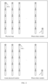
- FIG. 6 is a schematic diagram of a first infrared image and a physical map according to an embodiment of this application.
- the first infrared image includes a plurality of photovoltaic strings.
- Each of the plurality of photovoltaic strings includes five photovoltaic modules connected in series. Because the detectable light intensity of the first photovoltaic string is higher than or lower than the detectable light intensity of the another photovoltaic string, the image feature corresponding to the first photovoltaic string in the first infrared image is different from the image feature corresponding to the another photovoltaic string.
- the first photovoltaic string may be distinguished from the plurality of photovoltaic strings based on the first infrared image.
- the physical map includes a relative location relationship between the plurality of photovoltaic strings.
- a relative location relationship between a photovoltaic string 1 and a photovoltaic string 2 is that the photovoltaic string 2 is located on a right side of the photovoltaic string 1. It may be understood that, based on the relative location relationship between the plurality of photovoltaic strings and the first infrared image, it can be learned that the first photovoltaic string is located in Row 1 and Column 3. In other words, the first actual physical location of the first photovoltaic string is Row 1 and Column 3.
- the actual physical location of the photovoltaic string is obtained based on the infrared image, to prepare for subsequent update of the physical map based on the actual physical location of the photovoltaic string.
- the method before the first infrared image is received from the image collection terminal, the method further includes: sending a control indication to an inverter.
- the control indication is used to indicate the inverter to control the detectable light intensity of the first photovoltaic string to be higher than or lower than the detectable light intensity of the another photovoltaic string.
- the first infrared image is an infrared image obtained after the image collection terminal photographs the plurality of photovoltaic strings when the detectable light intensity of the first photovoltaic string is higher than or lower than the detectable light intensity of the another photovoltaic string.
- the inverter is connected to the plurality of photovoltaic strings.
- the control indication carries a threshold.
- the control indication is used to indicate the inverter to control the detectable light intensity of the first photovoltaic string to be higher than or lower than the threshold.
- the detectable light intensity of the another photovoltaic string is lower than the threshold.
- control indication is used to indicate the inverter to control the detectable light intensity of the first photovoltaic string to be higher than or lower than the threshold through adjusting an electrical performance parameter of the first photovoltaic string, and control the detectable light intensity of the another photovoltaic string to be lower than the threshold through adjusting an electrical performance parameter of the another photovoltaic string.
- the electrical performance parameter includes a current or a voltage.
- control indication is used to indicate the inverter to control the detectable light intensity of the first photovoltaic string to be higher than or lower than the threshold through switching an operation mode of the first photovoltaic string, and control the detectable light intensity of the another photovoltaic string to be lower than the threshold through switching an operation mode of the another photovoltaic string.
- the operation mode of the first photovoltaic string includes an open circuit, a short circuit, and a closed circuit.
- the control indication is used to indicate the inverter to control the detectable light intensity of the first photovoltaic string to be higher than or lower than the threshold through switching the first photovoltaic string from a closed circuit to an open circuit, and control the detectable light intensity of the another photovoltaic string to be lower than the threshold through switching the operation mode of the another photovoltaic string to a closed circuit.
- the detectable light intensity of the first photovoltaic string may be higher than or lower than the threshold in a current backflow manner, or the detectable light intensity of the first photovoltaic string may be higher than or lower than the threshold in a voltage backflow manner. This is not limited in this application.
- maximum power point tracking maximum power point tracking, MPPT
- the first photovoltaic string is connected to a first MPPT in the plurality of MPPTs.
- the control indication is used to indicate the first MPPT in the inverter to control the detectable light intensity of the first photovoltaic string to be higher than or lower than the threshold, and another MPPT in the inverter to control the detectable light intensity of the another photovoltaic string to be lower than the threshold.
- control indication is used to indicate the first MPPT in the inverter to control the detectable light intensity of the first photovoltaic string to be higher than or lower than the threshold through adjusting the electrical performance parameter of the first photovoltaic string, and the another MPPT in the inverter to control the detectable light intensity of the another photovoltaic string to be lower than the threshold through adjusting the electrical performance parameter of the another photovoltaic string.
- control indication is used to indicate the first MPPT in the inverter to control the detectable light intensity of the first photovoltaic string to be higher than or lower than the threshold through switching the operation mode of the first photovoltaic string, and the another MPPT in the inverter to control the detectable light intensity of the another photovoltaic string to be lower than the threshold through switching the operation mode of the another photovoltaic string.
- control indication is used to indicate the first MPPT in the inverter to control the detectable light intensity of the first photovoltaic string to be higher than or lower than the threshold through switching the first photovoltaic string from a closed circuit to an open circuit, and the another MPPT in the inverter to control the detectable light intensity of the another photovoltaic string to be lower than the threshold through switching the operation mode of the another photovoltaic string to a closed circuit.
- the method before the first infrared image is received from the image collection terminal, the method further includes: sending a control indication to a combiner box.
- the control indication is used to indicate the inverter to control the detectable light intensity of the first photovoltaic string to be higher than or lower than the detectable light intensity of the another photovoltaic string.
- the first infrared image is an infrared image obtained after the image collection terminal photographs the plurality of photovoltaic strings when the detectable light intensity of the first photovoltaic string is higher than or lower than the detectable light intensity of the another photovoltaic string.
- the combiner box is connected to the plurality of photovoltaic strings. Further, the control indication is used to indicate the combiner box to control the detectable light intensity of the first photovoltaic string to be higher than or lower than the threshold through adjusting an electrical performance parameter of the first photovoltaic string, and control the detectable light intensity of the another photovoltaic string to be lower than the threshold through adjusting an electrical performance parameter of the another photovoltaic string.
- the electrical performance parameter includes a current or a voltage.
- control indication is used to indicate the combiner box to control the detectable light intensity of the first photovoltaic string to be higher than or lower than the threshold through switching an operation mode of the first photovoltaic string, and control the detectable light intensity of the another photovoltaic string to be lower than the threshold through switching an operation mode of the another photovoltaic string.
- the operation mode of the first photovoltaic string includes an open circuit, a short circuit, and a closed circuit.
- control indication is used to indicate the combiner box to control the detectable light intensity of the first photovoltaic string to be higher than or lower than the threshold through switching the first photovoltaic string from a closed circuit to an open circuit, and control the detectable light intensity of the another photovoltaic string to be lower than the threshold through switching the operation mode of the another photovoltaic string to a closed circuit.
- an operation may be performed on the combiner box in a manual manner, so that the detectable light intensity of the first photovoltaic string is higher than or lower than the detectable light intensity of the another photovoltaic string.
- the another photovoltaic string is in a closed circuit; or at night, the another photovoltaic string is in a closed state.
- the detectable light intensity of the first photovoltaic string is higher than or lower than the detectable light intensity of the another photovoltaic string.
- a related operation does not need to be performed on the another photovoltaic string.
- control indication further carries a preset detection sequence.
- the control indication is used to indicate the inverter to perform actual physical location detection on the plurality of photovoltaic strings according to the preset detection sequence.
- the inverter controls detectable light intensity of a photovoltaic string in the plurality of photovoltaic strings to be higher than or lower than the threshold, and detectable light intensity of a photovoltaic string other than the photovoltaic string in the plurality of photovoltaic strings to be lower than the threshold.
- the image collection terminal obtains an infrared image through photographing when the detectable light intensity of the photovoltaic string in the plurality of photovoltaic strings is higher than or lower than the threshold, and the detectable light intensity of the photovoltaic string other than the photovoltaic string in the plurality of photovoltaic strings is lower than the threshold.
- the detectable light intensity of the first photovoltaic string is controlled to be higher than or lower than the detectable light intensity of the another photovoltaic string, so that the image collection terminal obtains the infrared image through photographing, to prepare for obtaining the actual physical location of the first photovoltaic string based on the physical map and the infrared image.
- the method further includes: receiving the first actual physical location sent from the first photovoltaic string.
- the first photovoltaic string includes a plurality of photovoltaic modules connected in series.
- a communication module is disposed on each of the plurality of photovoltaic modules.
- the first actual physical location is sent by a communication module corresponding to the first photovoltaic module.
- the first photovoltaic module is one of the plurality of photovoltaic modules.
- FIG. 7 is a schematic flowchart of another photovoltaic string location update method according to an embodiment of this application. As shown in FIG. 7 , the method further includes the following steps: 701: An inverter sends a logical location of a faulty photovoltaic string to a photovoltaic power station management system.
- the logical location of the faulty photovoltaic string is an identifier corresponding to the faulty photovoltaic string.
- the logical location of the faulty photovoltaic string may be a number corresponding to the faulty photovoltaic string. Further, the number corresponding to the faulty photovoltaic string is obtained through coding.
- the method before the logical location of the faulty photovoltaic string is received from the inverter, the method further includes: sending a fault detection indication to the inverter.
- the fault detection indication is used to indicate the inverter to perform fault detection on each of the plurality of photovoltaic strings.
- the inverter obtains a current value and a voltage value of each of the plurality of photovoltaic strings, and then processes the current value and the voltage value of each of the plurality of photovoltaic strings by using a first fault identification algorithm, to obtain a faulty photovoltaic string from the plurality of photovoltaic strings.
- a photovoltaic string having a current value and a voltage value different from a standard current value and a standard voltage value is screened by using the first fault identification algorithm.
- the fault detection indication may carry the standard current value and the standard voltage value.
- the photovoltaic power station management system obtains a physical location of the faulty photovoltaic string based on an updated physical map and the logical location of the faulty photovoltaic string.
- the second photovoltaic string is any one of the another photovoltaic string.
- the updated physical map is further used to indicate a correspondence between a second logical location of a second photovoltaic string and a second actual physical location.
- the updated physical map is further used to indicate a correspondence between a second logical location of the second photovoltaic string and a physical location of the second photovoltaic string in the physical map.
- the second logical location is an identifier corresponding to the second photovoltaic string.
- the second logical location may be a number corresponding to the second photovoltaic string.
- the second actual physical location of the another photovoltaic string may be the same as or different from the physical location in the physical map.
- the correspondence between the second logical location of the another photovoltaic string and the physical location does not need to be updated in the physical map.
- the correspondence between the second logical location of the another photovoltaic string and the physical location needs to be updated in the physical map.
- An image collection terminal receives the physical location of the faulty photovoltaic string sent by the photovoltaic power station management system.
- the physical location of the faulty photovoltaic string is used by the image collection terminal to perform photographing.
- the method further includes: receiving a fault type of the faulty photovoltaic module from the image collection terminal.
- the faulty photovoltaic module is at least one photovoltaic module of the faulty photovoltaic string.
- the fault type of the faulty photovoltaic module is obtained by the image collection terminal based on a second infrared image including the faulty photovoltaic module.
- the second infrared image is obtained through photographing performed by the image collection terminal based on the physical location of the faulty photovoltaic string.
- the fault type of the faulty photovoltaic module is obtained through processing the second infrared image by using a second fault identification algorithm by the image collection terminal.
- the second fault identification algorithm is used to compare the second infrared image with a plurality of template images, to set at least one fault type in one-to-one correspondence with at least one template image in the plurality of template images to the fault type corresponding to the second infrared image.
- Each of the plurality of template images corresponds to one fault type.
- the fault type of the faulty photovoltaic module includes at least one of the following: abnormal attenuation of output power of a photovoltaic module, potential induced degradation PID of a photovoltaic module, a failure of a battery unit in a photovoltaic module, a current mismatch of a photovoltaic module, a hot spot of a photovoltaic module, a short circuit of a diode in a photovoltaic module, a broken glass panel of a photovoltaic module, an open circuit in a photovoltaic module, or blocking of a photovoltaic module.
- the faulty photovoltaic module is finely determined, and the fault type of the faulty photovoltaic module is obtained, to prepare for subsequent operation and maintenance.
- the method may be applied to an electronic apparatus.
- the electronic apparatus may be, for example, a photovoltaic power station management system, a chip, or an apparatus including the chip.
- the method includes: receiving a logical location of a faulty photovoltaic string that is sent from an inverter; and obtaining a physical location of a faulty photovoltaic string based on the logical location of the faulty photovoltaic string; sending a physical location of the faulty photovoltaic string to an image collection terminal, where the physical location of the faulty photovoltaic string is used by the image collection terminal to perform photographing.
- the logical location of the faulty photovoltaic string that is sent from the inverter is received. For this process, refer to step 701 in FIG. 7 .
- the physical location of the faulty photovoltaic string is sent to the image collection terminal. For this process, refer to step 703 in FIG. 7 .
- the obtaining a physical location of a faulty photovoltaic string based on the logical location of the faulty photovoltaic string includes: obtaining the physical location of the faulty photovoltaic string based on the logical location of the faulty photovoltaic string and a correspondence between a logical location of a photovoltaic string and a physical location.
- the method before obtaining the physical location of the faulty photovoltaic string based on the logical location of the faulty photovoltaic string and the first correspondence between a logical location of a photovoltaic string and a physical location, the method further includes: obtaining, based on a physical map, a physical location of a first photovoltaic string corresponding to a first logical location in the physical map.
- the physical map is used to indicate a correspondence between a logical location of a photovoltaic string and a physical location of the photovoltaic string in the physical map.
- the photovoltaic string includes the first photovoltaic string.
- the physical location of the first photovoltaic string in the physical map is different from a first actual physical location of the first photovoltaic string, the physical location of the photovoltaic string in the physical map is updated to the first actual physical location, to obtain the updated physical map.
- the physical location of the first photovoltaic string corresponding to the first logical location in the physical map is obtained based on the physical map. For this process, refer to step 301 in FIG. 3 .
- the physical location of the photovoltaic string in the physical map is updated to the first actual physical location, to obtain the updated physical map. For this process, refer to step 302 in FIG. 3 .
- the physical map is updated when the actual physical location of the photovoltaic string is inconsistent with the physical location in the physical map.
- the following case is avoided:
- the actual physical location of the photovoltaic string is inconsistent with the physical location in the physical map, to prepare for subsequent operation and maintenance accurately performed on the photovoltaic module.
- the logical location of the faulty photovoltaic string is subsequently roughly determined, the physical location of the faulty photovoltaic string is obtained based on the correspondence between a logical location of a photovoltaic string and a physical location.
- the method further includes: receiving a first infrared image from an image collection terminal, where the first infrared image includes a plurality of photovoltaic strings, the first photovoltaic string is one of the plurality of photovoltaic strings, and an image feature corresponding to the first photovoltaic string in the first infrared image is different from an image feature corresponding to another photovoltaic string; and obtaining, based on the first infrared image, a physical location of a photovoltaic string whose image feature is different from the image feature corresponding to the another photovoltaic string, to obtain the first actual physical location.
- the first infrared image is received from the image collection terminal.
- step 501 in FIG. 5 The physical location of the photovoltaic string whose image feature is different from the image feature corresponding to the another photovoltaic string is obtained based on the first infrared image, to obtain the first actual physical location.
- step 502 in FIG. 5 refers to step 502 in FIG. 5 .
- the actual physical location of the photovoltaic string is obtained based on the infrared image, to prepare for subsequent update of the physical map based on the actual physical location of the photovoltaic string.
- the physical map is further used to indicate a relative physical location relationship between the plurality of photovoltaic strings.
- the obtaining, based on the first infrared image, a physical location of the photovoltaic string whose image feature is different from the image feature corresponding to the another photovoltaic string, to obtain the first actual physical location includes: obtaining the first actual physical location based on the relative physical location relationship between the plurality of photovoltaic strings and the first infrared image.
- the method before the first infrared image is received from the image collection terminal, the method further includes: sending a control indication to an inverter.
- the control indication is used to indicate the inverter to control the detectable light intensity of the first photovoltaic string to be higher than or lower than the detectable light intensity of the another photovoltaic string.
- the first infrared image is an infrared image obtained after the image collection terminal photographs the plurality of photovoltaic strings when the detectable light intensity of the first photovoltaic string is higher than or lower than the detectable light intensity of the another photovoltaic string.
- the control indication is sent to the inverter.
- the detectable light intensity of the first photovoltaic string is controlled to be higher than or lower than the detectable light intensity of the another photovoltaic string, so that the image collection terminal obtains the infrared image through photographing, to prepare for obtaining the actual physical location of the first photovoltaic string based on the physical map and the infrared image.
- the method further includes: receiving the first actual physical location sent from the first photovoltaic string.
- the first photovoltaic string includes a plurality of photovoltaic modules connected in series.
- a communication module is disposed on each of the plurality of photovoltaic modules.
- the first actual physical location is sent by a communication module corresponding to the first photovoltaic module.
- the first photovoltaic module is one of the plurality of photovoltaic modules.
- the method further includes: receiving a fault type of the faulty photovoltaic module from the image collection terminal, where the faulty photovoltaic module is at least one photovoltaic module of the faulty photovoltaic string, the fault type of the faulty photovoltaic module is obtained by the image collection terminal based on a second infrared image including the faulty photovoltaic module, and the second infrared image is obtained through photographing performed by the image collection terminal based on the physical location of the faulty photovoltaic string.
- the faulty photovoltaic module is finely determined, and the fault type of the faulty photovoltaic module is obtained, to prepare for subsequent operation and maintenance.
- FIG. 8 is a schematic diagram of a structure of a photovoltaic string location update apparatus according to an embodiment of this application.
- the apparatus 800 may be applied to the methods shown in FIG. 3 to FIG. 7 .
- the apparatus 800 includes a processing module 801 and a transceiver module 802.
- the processing module 801 is configured to obtain, based on a physical map, a physical location of a first photovoltaic string corresponding to a first logical location in the physical map.
- the physical map is used to indicate a correspondence between a logical location of a photovoltaic string and a physical location of the photovoltaic string in the physical map.
- the photovoltaic string includes the first photovoltaic string.
- the processing module 801 is further configured to: when the physical location of the first photovoltaic string in the physical map is different from a first actual physical location of the first photovoltaic string, update the physical location of the photovoltaic string in the physical map to the first actual physical location, to obtain the updated physical map.
- the physical location of the first photovoltaic string corresponding to the first logical location in the physical map is obtained based on the physical map. For this process, refer to step 301 in FIG. 3 .
- the physical location of the photovoltaic string in the physical map is updated to the first actual physical location, to obtain the updated physical map. For this process, refer to step 302 in FIG. 3 .
- the apparatus further includes a transceiver module.
- the transceiver module 802 is configured to receive a first infrared image from an image collection terminal.
- the first infrared image includes a plurality of photovoltaic strings.
- the first photovoltaic string is one of the plurality of photovoltaic strings.
- An image feature corresponding to the first photovoltaic string in the first infrared image is different from an image feature corresponding to another photovoltaic string.
- the processing module 801 is further configured to obtain, based on the first infrared image, a physical location of a photovoltaic string whose image feature is different from the image feature corresponding to the another photovoltaic string, to obtain the first actual physical location.
- the first infrared image is received from the image collection terminal.
- step 501 in FIG. 5 The physical location of the photovoltaic string whose image feature is different from the image feature corresponding to the another photovoltaic string is obtained based on the first infrared image, to obtain the first actual physical location.
- step 502 in FIG. 5 refers to step 502 in FIG. 5 .
- the physical map is further used to indicate a relative physical location relationship between the plurality of photovoltaic strings.
- the processing module 801 is specifically configured to obtain the first actual physical location based on the relative physical location relationship between the plurality of photovoltaic strings and the first infrared image.
- the transceiver module 802 before receiving the first infrared image sent by the image collection terminal, is further configured to send a control indication to an inverter, where the control indication is used to indicate the inverter to control detectable light intensity of the first photovoltaic string to be higher than or lower than detectable light intensity of the another photovoltaic string.
- the first infrared image is an infrared image obtained after the image collection terminal photographs the plurality of photovoltaic strings when the detectable light intensity of the first photovoltaic string is higher than or lower than the detectable light intensity of the another photovoltaic string.
- the control indication is sent to the inverter.
- the apparatus further includes the transceiver module 802.
- the transceiver module 802 is configured to receive the first actual physical location sent from the first photovoltaic string.
- the transceiver module 802 is further configured to receive a logical location of a faulty photovoltaic string that is sent by the inverter.
- the processing module 801 is further configured to obtain a physical location of the faulty photovoltaic string based on the updated physical map and the logical location of the faulty photovoltaic string.
- the transceiver module 802 is further configured to send the physical location of the faulty photovoltaic string to the image collection terminal.
- the physical location of the faulty photovoltaic string is used by the image collection terminal to perform photographing.
- the logical location of the faulty photovoltaic string that is sent from the inverter is received. For this process, refer to step 701 in FIG. 7 .
- the physical location of the faulty photovoltaic string is sent to the image collection terminal. For this process, refer to step 703 in FIG. 7 .
- the transceiver module 802 is further configured to receive a fault type of the faulty photovoltaic module from the image collection terminal.
- the faulty photovoltaic module is at least one photovoltaic module of the faulty photovoltaic string.
- the fault type of the faulty photovoltaic module is obtained by the image collection terminal based on a second infrared image including the faulty photovoltaic module.
- the second infrared image is obtained through photographing performed by the image collection terminal based on the physical location of the faulty photovoltaic string.
- FIG. 9 is a schematic diagram of a structure of another photovoltaic string location update apparatus according to an embodiment of this application.
- the apparatus 900 may be applied to the methods shown in FIG. 3 to FIG. 7 .
- the apparatus 900 includes a transceiver module 901 and a processing module 902.
- the transceiver module 901 is further configured to receive a logical location of a faulty photovoltaic string that is sent from an inverter.
- the processing module 902 is configured to obtain a physical location of the faulty photovoltaic string based on the logical location of the faulty photovoltaic string.
- the transceiver module 901 is further configured to send the physical location of the faulty photovoltaic string to the image collection terminal.
- the physical location of the faulty photovoltaic string is used by the image collection terminal to perform photographing.
- the logical location of the faulty photovoltaic string that is sent from the inverter is received.
- the physical location of the faulty photovoltaic string is sent to the image collection terminal.
- the processing module 902 is specifically configured to obtain the physical location of the faulty photovoltaic string based on the logical location of the faulty photovoltaic string and a correspondence between a logical location of a photovoltaic string and a physical location.
- the processing module 902 before obtaining the physical location of the faulty photovoltaic string based on the logical location of the faulty photovoltaic string and the first correspondence between a logical location of a photovoltaic string and a physical location, is further configured to obtain, based on a physical map, a physical location of a first photovoltaic string corresponding to a first logical location in the physical map.
- the physical map is used to indicate a correspondence between a logical location of a photovoltaic string and a physical location of the photovoltaic string in the physical map.
- the photovoltaic string includes the first photovoltaic string.
- the processing module 902 is further configured to: when the physical location of the first photovoltaic string in the physical map is different from a first actual physical location of the first photovoltaic string, update the physical location of the photovoltaic string in the physical map to the first actual physical location, to obtain the updated physical map.
- the physical location of the first photovoltaic string corresponding to the first logical location in the physical map is obtained based on the physical map. For this process, refer to step 301 in FIG. 3 .
- the physical location of the photovoltaic string in the physical map is updated to the first actual physical location, to obtain the updated physical map. For this process, refer to step 302 in FIG. 3 .
- the transceiver module 901 is further configured to receive a first infrared image from the image collection terminal.
- the first infrared image includes a plurality of photovoltaic strings.
- the first photovoltaic string is one of the plurality of photovoltaic strings.
- An image feature corresponding to the first photovoltaic string in the first infrared image is different from an image feature corresponding to another photovoltaic string.
- the processing module 902 is further configured to obtain, based on the first infrared image, a physical location of a photovoltaic string whose image feature is different from the image feature corresponding to the another photovoltaic string, to obtain the first actual physical location.
- the first infrared image is received from the image collection terminal.
- step 501 in FIG. 5 The physical location of the photovoltaic string whose image feature is different from the image feature corresponding to the another photovoltaic string is obtained based on the first infrared image, to obtain the first actual physical location.
- step 502 in FIG. 5 refers to step 502 in FIG. 5 .
- the physical map is further used to indicate a relative physical location relationship between the plurality of photovoltaic strings.
- the processing module 902 is specifically configured to obtain the first actual physical location based on the relative physical location relationship between the plurality of photovoltaic strings and the first infrared image.
- the transceiver module before receiving the first infrared image from the image collection terminal, is further configured to send a control indication to the inverter.
- the control indication is used to indicate the inverter to control detectable light intensity of the first photovoltaic string to be higher than or lower than detectable light intensity of the another photovoltaic string.
- the first infrared image is an infrared image obtained after the image collection terminal photographs the plurality of photovoltaic strings when the detectable light intensity of the first photovoltaic string is higher than or lower than the detectable light intensity of the another photovoltaic string.
- the control indication is sent to the inverter.
- the transceiver module 901 is further configured to receive the first actual physical location sent from the first photovoltaic string.
- the first photovoltaic string includes a plurality of photovoltaic modules connected in series.
- a communication module is disposed on each of the plurality of photovoltaic modules.
- the first actual physical location is sent by a communication module corresponding to the first photovoltaic module.
- the first photovoltaic module is one of the plurality of photovoltaic modules.
- the transceiver module 901 is further configured to receive a fault type of a faulty photovoltaic module from the image collection terminal.
- the faulty photovoltaic module is at least one photovoltaic module of the faulty photovoltaic string.
- the fault type of the faulty photovoltaic module is obtained by the image collection terminal based on a second infrared image including the faulty photovoltaic module.
- the second infrared image is obtained through photographing performed by the image collection terminal based on the physical location of the faulty photovoltaic string.
- FIG. 10 is a schematic diagram of a structure of another photovoltaic string location update apparatus according to an embodiment of this application.
- the apparatus 1000 includes at least one processor 1001, at least one memory 1002, and at least one communication interface 1003.
- the processor 1001, the memory 1002, and the communication interface 1003 are connected and communicate with each other by using a communication bus.
- the processor 1001 may be a general-purpose central processing unit (CPU), a microprocessor, an application-specific integrated circuit (application-specific integrated circuit, ASIC), or one or more integrated circuits configured to control execution of the foregoing solution program.
- CPU central processing unit
- ASIC application-specific integrated circuit
- the memory 1002 may be, but is not limited to, a read-only memory (read-only memory, ROM) or another type of static storage device capable of storing static information and instructions, a random access memory (random access memory, RAM) or another type of dynamic storage device capable of storing information and instructions, an electrically erasable programmable read-only memory (Electrically Erasable Programmable Read-Only Memory, EEPROM), a compact disc read-only memory (Compact Disc Read-Only Memory, CD-ROM) or another compact disc storage, an optical disc storage (including a compact disc, a laser disc, an optical disc, a digital versatile disc, a Blu-ray disc, and the like), a magnetic disk storage medium or another magnetic storage device, or any other medium that can be used to carry or store expected program code in an instruction or data structure form and that can be accessed by a computer.
- the memory may exist independently, and is connected to the processor through the bus. The memory may alternatively be integrated with the processor.
- the memory 1002 is configured to store application program code for performing a photovoltaic string location update method.
- the application program code is controlled and executed by the processor 1001.
- the processor 1001 is configured to execute the application program code stored in the memory 1002.
- the communication interface 1003 is configured to communicate with another device or a communication network, for example, the Ethernet, a radio access network (RAN), and a wireless local area network (Wireless Local Area Networks, WLAN).
- a communication network for example, the Ethernet, a radio access network (RAN), and a wireless local area network (Wireless Local Area Networks, WLAN).
- RAN radio access network
- WLAN Wireless Local Area Networks
- An embodiment of this application further provides a computer storage medium.
- the computer storage medium may store a program. When the program is executed, some or all steps of any photovoltaic string location update method recorded in the foregoing method embodiments are performed.
- the photovoltaic string location update system includes a photovoltaic power station management system.
- the photovoltaic power station management system is configured to obtain, based on a physical map, a physical location of a first photovoltaic string corresponding to a first logical location in the physical map.
- the physical map is used to indicate a correspondence between a logical location of a photovoltaic string and a physical location of the photovoltaic string in the physical map.
- the photovoltaic string includes the first photovoltaic string.
- the photovoltaic power station management system is further configured to: when the physical location of the first photovoltaic string in the physical map is different from a first actual physical location of the first photovoltaic string, update the physical location of the photovoltaic string in the physical map to the first actual physical location, to obtain the updated physical map.
- the physical location of the first photovoltaic string corresponding to the first logical location in the physical map is obtained based on the physical map. For this process, refer to step 301 in FIG. 3 .
- the physical location of the photovoltaic string in the physical map is updated to the first actual physical location, to obtain the updated physical map. For this process, refer to step 302 in FIG. 3 .
- the physical map is updated when the actual physical location of the photovoltaic string is inconsistent with the physical location in the physical map.
- the following case is avoided: The actual physical location of the photovoltaic string is inconsistent with the physical location in the physical map, to prepare for subsequent operation and maintenance accurately performed on a photovoltaic module.
- the photovoltaic string location update system further includes an image collection terminal.
- the image collection terminal is configured to send a first infrared image to the photovoltaic power station management system.
- the first infrared image includes a plurality of photovoltaic strings.
- the first photovoltaic string is one of the plurality of photovoltaic strings.
- An image feature corresponding to the first photovoltaic string in the first infrared image is different from an image feature corresponding to another photovoltaic string.
- the photovoltaic power station management system is configured to obtain, based on the first infrared image, a physical location of a photovoltaic string whose image feature is different from the image feature corresponding to the another photovoltaic string, to obtain the first actual physical location.
- the first infrared image is sent to the photovoltaic power station management system.
- step 501 in FIG. 5 The physical location of the photovoltaic string whose image feature is different from the image feature corresponding to the another photovoltaic string is obtained based on the first infrared image, to obtain the first actual physical location.
- step 502 in FIG. 5 refers to step 502 in FIG. 5 .
- the physical map is further used to indicate a relative physical location relationship between the plurality of photovoltaic strings.
- the photovoltaic station management system is specifically configured to obtain the first actual physical location based on the relative physical location relationship between the plurality of photovoltaic strings and the first infrared image.
- the photovoltaic string location update system further includes an inverter.
- the inverter is configured to receive a control indication from the photovoltaic power station management system.
- the control indication is used to indicate the inverter to control detectable light intensity of the first photovoltaic string to be higher than or lower than detectable light intensity of the another photovoltaic string.
- the first infrared image is an infrared image obtained after the image collection terminal photographs the plurality of photovoltaic strings when the detectable light intensity of the first photovoltaic string is higher than or lower than the detectable light intensity of the another photovoltaic string.
- the control indication is received from the photovoltaic power station management system. For this process, refer to related content of the control indication in FIG. 5 .
- the detectable light intensity of the first photovoltaic string is controlled to be higher than or lower than the detectable light intensity of the another photovoltaic string, so that the image collection terminal obtains the infrared image through photographing, to prepare for obtaining the actual physical location of the first photovoltaic string based on the infrared image.
- the photovoltaic power station management system is configured to receive the first actual physical location sent from the first photovoltaic string.
- the first photovoltaic string includes a plurality of photovoltaic modules connected in series.
- a communication module is disposed on each of the plurality of photovoltaic modules.
- the first actual physical location is sent by a communication module corresponding to the first photovoltaic module.
- the first photovoltaic module is one of the plurality of photovoltaic modules.
- the inverter is further configured to send a logical location of a faulty photovoltaic string to the photovoltaic power station management system.
- the photovoltaic power station management system is further configured to obtain a physical location of the faulty photovoltaic string based on the updated physical map and the logical location of the faulty photovoltaic string.
- the image collection terminal is further configured to receive the physical location of the faulty photovoltaic string from the photovoltaic power station management system. The physical location of the faulty photovoltaic string is used by the image collection terminal to perform photographing.
- the logical location of the faulty photovoltaic string is sent to the photovoltaic power station management system. For this process, refer to step 701 in FIG. 7 .
- the physical location of the faulty photovoltaic string is received from the photovoltaic power station management system. For this process, refer to step 703 in FIG. 7 .
- the photovoltaic power station management system is further configured to receive a fault type of a faulty photovoltaic module from the image collection terminal.
- the faulty photovoltaic module is at least one photovoltaic module of the faulty photovoltaic string.
- the fault type of the faulty photovoltaic module is obtained by the image collection terminal based on a second infrared image including the faulty photovoltaic module.
- the second infrared image is obtained through photographing performed by the image collection terminal based on the physical location of the faulty photovoltaic string.
- the faulty photovoltaic module is finely determined, and the fault type of the faulty photovoltaic module is obtained, to prepare for subsequent operation and maintenance.
- the photovoltaic string location update system includes a photovoltaic power station management system, an inverter, and an image collection terminal.
- the inverter is configured to send a logical location of a faulty photovoltaic string to the photovoltaic power station management system.
- the photovoltaic power station management system is configured to obtain a physical location of the faulty photovoltaic string based on the logical location of the faulty photovoltaic string.
- the image collection terminal is configured to receive the physical location of the faulty photovoltaic string from the photovoltaic power station management system. The physical location of the faulty photovoltaic string is used by the image collection terminal to perform photographing.
- the logical location of the faulty photovoltaic string is sent to the photovoltaic power station management system. For this process, refer to step 701 in FIG. 7 .
- the physical location of the faulty photovoltaic string is received from the photovoltaic power station management system. For this process, refer to step 703 in FIG. 7 .
- the photovoltaic power station management system is specifically configured to obtain the physical location of the faulty photovoltaic string based on the logical location of the faulty photovoltaic string and a correspondence between a logical location of a photovoltaic string and a physical location.
- the photovoltaic power station management system is further configured to obtain, based on a physical map, a physical location of a first photovoltaic string corresponding to a first logical location in the physical map.
- the physical map is used to indicate a correspondence between a logical location of a photovoltaic string and a physical location of the photovoltaic string in the physical map.
- the photovoltaic string includes the first photovoltaic string.
- the photovoltaic power station management system is further configured to: when the physical location of the first photovoltaic string in the physical map is different from a first actual physical location of the first photovoltaic string, update the physical location of the photovoltaic string in the physical map to the first actual physical location, to obtain the updated physical map.
- the physical location of the first photovoltaic string corresponding to the first logical location in the physical map is obtained based on the physical map. For this process, refer to step 301 in FIG. 3 .
- the physical location of the photovoltaic string in the physical map is updated to the first actual physical location, to obtain the updated physical map. For this process, refer to step 302 in FIG. 3 .
- the physical map is updated when the actual physical location of the photovoltaic string is inconsistent with the physical location in the physical map.
- the following case is avoided:
- the actual physical location of the photovoltaic string is inconsistent with the physical location in the physical map, to prepare for subsequent operation and maintenance accurately performed on the photovoltaic module.
- the logical location of the faulty photovoltaic string is subsequently roughly determined, the physical location of the faulty photovoltaic string is obtained based on the correspondence between a logical location of a photovoltaic string and a physical location.
- the image collection terminal is further configured to send a first infrared image to the photovoltaic power station management system.
- the first infrared image includes a plurality of photovoltaic strings.
- the first photovoltaic string is one of the plurality of photovoltaic strings.
- An image feature corresponding to the first photovoltaic string in the first infrared image is different from an image feature corresponding to another photovoltaic string.
- the photovoltaic power station management system is further configured to obtain, based on the first infrared image, a physical location of a photovoltaic string whose image feature is different from the image feature corresponding to the another photovoltaic string, to obtain the first actual physical location.
- the first infrared image is sent to the photovoltaic power station management system.
- step 501 in FIG. 5 The physical location of the photovoltaic string whose image feature is different from the image feature corresponding to the another photovoltaic string is obtained based on the first infrared image, to obtain the first actual physical location.
- step 502 in FIG. 5 refers to step 502 in FIG. 5 .
- the actual physical location of the photovoltaic string is obtained based on the infrared image, to prepare for subsequent update of the physical map based on the actual physical location of the photovoltaic string.
- the photovoltaic power station management system is specifically configured to obtain the first actual physical location based on the relative physical location relationship between the plurality of photovoltaic strings and the first infrared image.
- the photovoltaic string location update system further includes the inverter.
- the inverter is configured to receive a control indication from the photovoltaic power station management system.
- the control indication is used to indicate the inverter to control detectable light intensity of the first photovoltaic string to be higher than or lower than detectable light intensity of the another photovoltaic string.
- the first infrared image is an infrared image obtained after the image collection terminal photographs the plurality of photovoltaic strings when the detectable light intensity of the first photovoltaic string is higher than or lower than the detectable light intensity of the another photovoltaic string.
- the control indication is received from the photovoltaic power station management system. For this process, refer to related content of the control indication in FIG. 5 .
- the detectable light intensity of the first photovoltaic string is controlled to be higher than or lower than the detectable light intensity of the another photovoltaic string, so that the image collection terminal obtains the infrared image through photographing, to prepare for obtaining the actual physical location of the first photovoltaic string based on the physical map and the infrared image.
- the photovoltaic power station management system is further configured to receive the first actual physical location sent from the first photovoltaic string.
- the first photovoltaic string includes a plurality of photovoltaic modules connected in series.
- a communication module is disposed on each of the plurality of photovoltaic modules.
- the first actual physical location is sent by a communication module corresponding to the first photovoltaic module.
- the first photovoltaic module is one of the plurality of photovoltaic modules.
- the photovoltaic power station management system is further configured to receive a fault type of a faulty photovoltaic module from the image collection terminal.
- the faulty photovoltaic module is at least one photovoltaic module of the faulty photovoltaic string.
- the fault type of the faulty photovoltaic module is obtained by the image collection terminal based on a second infrared image including the faulty photovoltaic module.
- the second infrared image is obtained through photographing performed by the image collection terminal based on the physical location of the faulty photovoltaic string.
- the faulty photovoltaic module is finely determined, and the fault type of the faulty photovoltaic module is obtained, to prepare for subsequent operation and maintenance.
- division into the units is merely logical function division and may be another division in actual implementation.
- a plurality of units or components may be combined or integrated into another system, or some features may be ignored or not performed.
- the displayed or discussed mutual couplings or direct couplings or communication connections may be implemented through some interfaces.
- the indirect couplings or communication connections between the apparatuses or units may be implemented in electronic, mechanical, or other forms.
- the units described as separate parts may or may not be physically separate, and parts displayed as units may or may not be physical units. In other words, the units or the parts may be located in one location, or may be distributed on a plurality of network units. Some or all of the units may be selected based on actual requirements to achieve the objectives of the solutions of embodiments.
- All or some of the foregoing embodiments may be implemented through software, hardware, firmware, or any combination thereof.
- the embodiments may be implemented completely or partially in a form of a computer program product.
- the computer program product includes one or more computer instructions.
- the computer may be a general-purpose computer, a special-purpose computer, a computer network, or another programmable apparatus.
- the computer instructions may be stored in a computer-readable storage medium, or may be transmitted by using the computer-readable storage medium.
- the computer instructions may be transmitted from one website, computer, server, or data center to another website, computer, server, or data center in a wired (for example, a coaxial cable, an optical fiber, or a digital subscriber line (digital subscriber line, DSL)) or wireless (for example, infrared, radio, or microwave) manner.
- the computer-readable storage medium may be any usable medium accessible by a computer, or a data storage device, such as a server or a data center, integrating one or more usable media.
- the usable medium may be a read-only memory (read-only memory, ROM); a random access memory (random access memory, RAM); or a magnetic medium, for example, a floppy disk, a hard disk, a magnetic tape, or a magnetic disk; an optical medium, for example, a digital versatile disc (digital versatile disc, DVD); a semiconductor medium, for example, a solid-state disk (solid-state disk, SSD); or the like
Landscapes
- Engineering & Computer Science (AREA)
- Business, Economics & Management (AREA)
- Theoretical Computer Science (AREA)
- General Physics & Mathematics (AREA)
- Physics & Mathematics (AREA)
- Human Resources & Organizations (AREA)
- Economics (AREA)
- Strategic Management (AREA)
- General Business, Economics & Management (AREA)
- Marketing (AREA)
- Health & Medical Sciences (AREA)
- Tourism & Hospitality (AREA)
- Quality & Reliability (AREA)
- Entrepreneurship & Innovation (AREA)
- Databases & Information Systems (AREA)
- Public Health (AREA)
- Primary Health Care (AREA)
- General Health & Medical Sciences (AREA)
- Operations Research (AREA)
- Water Supply & Treatment (AREA)
- General Engineering & Computer Science (AREA)
- Data Mining & Analysis (AREA)
- Computer Vision & Pattern Recognition (AREA)
- Power Engineering (AREA)
- Game Theory and Decision Science (AREA)
- Educational Administration (AREA)
- Development Economics (AREA)
- Remote Sensing (AREA)
- Photovoltaic Devices (AREA)
Claims (10)
- Verfahren zur Ortsaktualisierung eines fotovoltaischen Strangs für ein Fotovoltaik-Kraftwerk, das mindestens einen Wechselrichter (103) umfasst, der mit einer Vielzahl von fotovoltaischen Strängen verbunden ist, umfassend:Erlangen (301), basierend auf einer physischen Karte, die Zeilen und Spalten aufweist und die Vielzahl von fotovoltaischen Strängen anzeigt, die in Spaltenrichtung angeordnet sind und jeweils eine Vielzahl von fotovoltaischen Modulen beinhalten, die in Zeilenrichtung in Reihe verbunden sind, eines physischen Orts eines ersten fotovoltaischen Strangs (PV1), der einem ersten logischen Ort in der physischen Karte entspricht, wobei der logische Ort des ersten fotovoltaischen Strangs eine Kennung ist, die dem ersten fotovoltaischen Strang entspricht, und wobei der physische Ort eine Zeile/Spalte ist, wo sich der erste fotovoltaische Strang in der physischen Karte befindet, wobei die physische Karte verwendet wird, um eine Entsprechung zwischen einem logischen Ort eines fotovoltaischen Strangs und einem physischen Ort des fotovoltaischen Strangs in der physischen Karte anzugeben, und der fotovoltaische Strang den ersten fotovoltaischen Strang umfasst; undwenn sich der physische Ort des ersten fotovoltaischen Strangs in der physischen Karte von einem ersten tatsächlichen physischen Ort des ersten fotovoltaischen Strangs unterscheidet, Aktualisieren (302) des physischen Orts des fotovoltaischen Strangs in der physischen Karte auf den ersten tatsächlichen physischen Ort, um eine aktualisierte physische Karte zu erlangen;Empfangen (501) eines ersten Infrarotbildes von einem Bilderfassungsendgerät (104), wobei das erste Infrarotbild eine Vielzahl von fotovoltaischen Strängen umfasst, der erste fotovoltaische Strang einer der Vielzahl von fotovoltaischen Strängen ist und ein Bildmerkmal, das dem ersten fotovoltaischen Strang in dem ersten Infrarotbild entspricht, sich von einem Bildmerkmal unterscheidet, das einem anderen fotovoltaischen Strang entspricht; undErlangen (502), basierend auf dem ersten Infrarotbild, eines physischen Orts eines fotovoltaischen Strangs, dessen Bildmerkmal sich von dem Bildmerkmal unterscheidet, das dem anderen fotovoltaischen Strang entspricht, um den ersten tatsächlichen physischen Ort zu erlangen.
- Verfahren nach Anspruch 1, wobei das Verfahren vor dem Empfangen des ersten Infrarotbildes von einem Bilderfassungsendgerät (104) ferner Folgendes umfasst:Senden einer Steueranzeige an den Wechselrichter (103), wobei die Steueranzeige verwendet wird, um dem Wechselrichter (103) anzuzeigen, die erkennbare Lichtintensität des ersten fotovoltaischen Strangs so zu steuern, dass sie höher oder niedriger als die erkennbare Lichtintensität des anderen fotovoltaischen Strangs ist, wobeidas erste Infrarotbild ein Infrarotbild ist, das erlangt wird, nachdem das Bilderfassungsendgerät (104) die Vielzahl von fotovoltaischen Strängen fotografiert hat, wenn die erkennbare Lichtintensität des ersten fotovoltaischen Strangs höher oder niedriger als die erkennbare Lichtintensität des anderen fotovoltaischen Strangs ist.
- Verfahren nach Anspruch 1, wobei das Verfahren ferner Folgendes umfasst:
Empfangen (703) des ersten tatsächlichen physischen Orts, der von dem ersten fotovoltaischen Strang gesendet wird. - Verfahren nach Anspruch 3, wobei das Verfahren ferner Folgendes umfasst:Empfangen (701) eines logischen Orts eines fehlerhaften fotovoltaischen Strangs von dem Wechselrichter (103);Erlangen (702) eines physischen Orts des fehlerhaften fotovoltaischen Strangs basierend auf der aktualisierten physischen Karte und dem logischen Ort des fehlerhaften fotovoltaischen Strangs; undSenden (703) des physischen Orts des fehlerhaften fotovoltaischen Strangs an das Bilderfassungsendgerät (104), wobei der physische Ort des fehlerhaften fotovoltaischen Strangs durch das Bilderfassungsendgerät (104) zum Durchführen des Fotografierens verwendet wird.
- Verfahren nach Anspruch 4, wobei das Verfahren ferner Folgendes umfasst:
Empfangen eines Fehlertyps eines fehlerhaften fotovoltaischen Moduls von dem Bilderfassungsendgerät (104), wobei das fehlerhafte fotovoltaische Modul mindestens ein fotovoltaisches Modul des fehlerhaften fotovoltaischen Strangs ist, der Fehlertyp des fehlerhaften fotovoltaischen Moduls durch das Bilderfassungsendgerät (104) basierend auf einem zweiten Infrarotbild erlangt wird, das das fehlerhafte fotovoltaische Modul umfasst, und das zweite Infrarotbild durch Fotografieren erlangt wird, das durch das Bilderfassungsendgerät (104) basierend auf dem physischen Ort des fehlerhaften fotovoltaischen Strangs durchgeführt wird. - System (101) zur Ortsaktualisierung eines fotovoltaischen Strangs für ein Fotovoltaik-Kraftwerk, das mindestens einen Wechselrichter (103) umfasst, der mit einer Vielzahl von fotovoltaischen Strängen verbunden ist, wobei das System (101) zur Ortsaktualisierung eines fotovoltaischen Strangs ein Managementsystem (101) für das Fotovoltaik-Kraftwerk umfasst; wobei das Managementsystem (101) für das Fotovoltaik-Kraftwerk zu Folgendem konfiguriert ist: Erlangen, basierend auf einer physischen Karte, die Zeilen und Spalten aufweist und die Vielzahl von fotovoltaischen Strängen anzeigt, die in Spaltenrichtung angeordnet sind und jeweils eine Vielzahl von fotovoltaischen Modulen beinhalten, die in Zeilenrichtung in Reihe verbunden sind, eines physischen Orts eines ersten fotovoltaischen Strangs (PV1), der einem ersten logischen Ort in der physischen Karte entspricht, wobei der logische Ort des ersten fotovoltaischen Strangs eine Kennung ist, die dem ersten fotovoltaischen Strang entspricht, und wobei der physische Ort eine Zeile/Spalte ist, wo der erste fotovoltaische Strang in der physischen Karte angezeigt wird, wobei die physische Karte verwendet wird, um eine Entsprechung zwischen einem logischen Ort eines fotovoltaischen Strangs und einem physischen Ort des fotovoltaischen Strangs in der physischen Karte anzugeben, und der fotovoltaische Strang den ersten fotovoltaischen Strang umfasst; undwobei das Managementsystem (101) für das Fotovoltaik-Kraftwerk ferner zu Folgendem konfiguriert ist: wenn sich der physische Ort des ersten fotovoltaischen Strangs in der physischen Karte von einem ersten tatsächlichen physischen Ort des ersten fotovoltaischen Strangs unterscheidet, Aktualisieren des physischen Orts des fotovoltaischen Strangs in der physischen Karte auf den ersten tatsächlichen physischen Ort, um eine aktualisierte physische Karte zu erlangen; undwobei das System (101) zur Ortsaktualisierung eines fotovoltaischen Strangs ferner ein Bilderfassungsendgerät (104) umfasst;wobei das Bilderfassungsendgerät (104) zum Senden eines ersten Infrarotbildes an das Managementsystem (101) für das Fotovoltaik-Kraftwerk konfiguriert ist, wobei das erste Infrarotbild eine Vielzahl von fotovoltaischen Strängen umfasst, der erste fotovoltaische Strang einer der Vielzahl von fotovoltaischen Strängen ist und ein Bildmerkmal, das dem ersten fotovoltaischen Strang in dem ersten Infrarotbild entspricht, sich von einem Bildmerkmal unterscheidet, das einem anderen fotovoltaischen Strang entspricht; unddas Managementsystem (101) für das Fotovoltaik-Kraftwerk ferner zum Erlangen, basierend auf dem ersten Infrarotbild, eines physischen Orts eines fotovoltaischen Strangs konfiguriert ist, dessen Bildmerkmal sich von dem Bildmerkmal unterscheidet, das dem anderen fotovoltaischen Strang entspricht, um den ersten tatsächlichen physischen Ort zu erlangen.
- System (101) nach Anspruch 6, wobei das System (101) zur Ortsaktualisierung eines fotovoltaischen Strangs ferner den Wechselrichter (103) umfasst;wobei der Wechselrichter (103) zum Empfangen einer Steueranzeige von dem Managementsystem (101) für das Fotovoltaik-Kraftwerk konfiguriert ist, wobei die Steueranzeige verwendet wird, um dem Wechselrichter (103) anzuzeigen, die erkennbare Lichtintensität des ersten fotovoltaischen Strangs so zu steuern, dass sie höher oder niedriger als die erkennbare Lichtintensität des anderen fotovoltaischen Strangs ist; unddas erste Infrarotbild ein Infrarotbild ist, das erlangt wird, nachdem das Bilderfassungsendgerät (104) die Vielzahl von fotovoltaischen Strängen fotografiert hat, wenn die erkennbare Lichtintensität des ersten fotovoltaischen Strangs höher oder niedriger als die erkennbare Lichtintensität des anderen fotovoltaischen Strangs ist.
- System (101) nach Anspruch 6, wobei das Managementsystem (101) für das Fotovoltaik-Kraftwerk dazu konfiguriert ist, den ersten tatsächlichen physischen Ort zu empfangen, der von dem ersten fotovoltaischen Strang gesendet wird.
- System (101) nach Anspruch 7, wobeider Wechselrichter (103) ferner zum Senden eines logischen Orts eines fehlerhaften fotovoltaischen Strangs an das Managementsystem (101) für das Fotovoltaik-Kraftwerk konfiguriert ist;das Managementsystem (101) für das Fotovoltaik-Kraftwerk ferner zum Erlangen eines physischen Orts des fehlerhaften fotovoltaischen Strangs basierend auf der aktualisierten physischen Karte und dem logischen Ort des fehlerhaften fotovoltaischen Strangs konfiguriert ist; unddas Bilderfassungsendgerät (104) ferner zum Empfangen des physischen Orts des fehlerhaften fotovoltaischen Strangs von dem Managementsystem (101) für das Fotovoltaik-Kraftwerk konfiguriert ist, wobei der physische Ort des fehlerhaften fotovoltaischen Strangs durch das Bilderfassungsendgerät (104) zum Durchführen des Fotografierens verwendet wird.
- System (102, 800, 900, 1000) nach Anspruch 9, wobei das Managementsystem (101) für das Fotovoltaik-Kraftwerk ferner zum Empfangen eines Fehlertyps eines fehlerhaften fotovoltaischen Moduls von dem Bilderfassungsendgerät (104) konfiguriert ist, wobei das fehlerhafte fotovoltaische Modul mindestens ein fotovoltaisches Modul des fehlerhaften fotovoltaischen Strangs ist, der Fehlertyp des fehlerhaften fotovoltaischen Moduls durch das Bilderfassungsendgerät (104) basierend auf einem zweiten Infrarotbild erlangt wird, das das fehlerhafte fotovoltaische Modul umfasst, und das zweite Infrarotbild durch das Bilderfassungsendgerät (104) basierend auf dem physischen Ort des fehlerhaften fotovoltaischen Strangs fotografiert wird.
Applications Claiming Priority (2)
| Application Number | Priority Date | Filing Date | Title |
|---|---|---|---|
| CN202010075397.6A CN113157830B (zh) | 2020-01-22 | 2020-01-22 | 一种光伏组串的位置更新方法和装置 |
| PCT/CN2020/113622 WO2021147329A1 (zh) | 2020-01-22 | 2020-09-04 | 一种光伏组串的位置更新方法和装置 |
Publications (3)
| Publication Number | Publication Date |
|---|---|
| EP4080378A1 EP4080378A1 (de) | 2022-10-26 |
| EP4080378A4 EP4080378A4 (de) | 2023-02-08 |
| EP4080378B1 true EP4080378B1 (de) | 2024-11-06 |
Family
ID=76881786
Family Applications (1)
| Application Number | Title | Priority Date | Filing Date |
|---|---|---|---|
| EP20915266.9A Active EP4080378B1 (de) | 2020-01-22 | 2020-09-04 | Verfahren und vorrichtung zur ortsaktualisierung eines fotovoltaischen strangs |
Country Status (5)
| Country | Link |
|---|---|
| US (1) | US12531510B2 (de) |
| EP (1) | EP4080378B1 (de) |
| CN (1) | CN113157830B (de) |
| ES (1) | ES2998839T3 (de) |
| WO (1) | WO2021147329A1 (de) |
Families Citing this family (2)
| Publication number | Priority date | Publication date | Assignee | Title |
|---|---|---|---|---|
| CN113963370B (zh) * | 2021-10-27 | 2025-08-12 | 阳光智维科技股份有限公司 | 一种光伏电站中光伏设备的编号方法及编号装置 |
| US12475416B2 (en) | 2023-09-26 | 2025-11-18 | Hanwha Solutions Corporation | Self-discovery of PV array installation mapping using wireless communication methods |
Family Cites Families (20)
| Publication number | Priority date | Publication date | Assignee | Title |
|---|---|---|---|---|
| US10193347B2 (en) * | 2013-03-29 | 2019-01-29 | Enphase Energy, Inc. | Method and apparatus for improved burst mode during power conversion |
| US11099008B2 (en) * | 2014-12-15 | 2021-08-24 | Sony Corporation | Capture device assembly, three-dimensional shape measurement device, and motion detection device |
| CN104796082A (zh) * | 2015-04-22 | 2015-07-22 | 中国科学院广州能源研究所 | 一种光伏发电系统在线故障诊断系统及方法 |
| CN104917460B (zh) * | 2015-06-03 | 2017-06-06 | 华为技术有限公司 | 一种光伏电池组件的监测方法及装置 |
| CN104899936B (zh) * | 2015-06-16 | 2017-06-13 | 深圳市联翼风电技术有限公司 | 一种基于图像识别的光伏组件故障提示方法及系统 |
| CN205249118U (zh) * | 2015-09-25 | 2016-05-18 | 日月元科技(深圳)有限公司 | 双路最大功率点追踪离网型太阳能逆变器装置 |
| US9588058B1 (en) * | 2015-12-29 | 2017-03-07 | Lawrence Livermore National Security, Llc | Non-destructive evaluation of water ingress in photovoltaic modules |
| CN105743439B (zh) * | 2016-02-29 | 2019-02-26 | 华为技术有限公司 | 光伏电池组串运行参数的检测方法及相关装置 |
| CN106052700A (zh) * | 2016-07-13 | 2016-10-26 | 四川九阵妙凰科技集团有限公司 | 一种室内导航地图及导航方法 |
| CN107782764B (zh) * | 2016-08-25 | 2021-02-23 | 成都鼎桥通信技术有限公司 | 一种光伏组件的故障识别方法 |
| US20200099335A1 (en) * | 2017-05-17 | 2020-03-26 | Mahindra Susten Pvt. Ltd. | A mobile laboratory for testing photovoltaic (pv) modules |
| CN107769250B (zh) * | 2017-11-07 | 2019-12-17 | 华为数字技术(苏州)有限公司 | 物理地址确定方法、装置、设备及存储介质 |
| CN108092622B (zh) * | 2017-12-14 | 2023-09-05 | 中国计量大学 | 一种基于电阻计算的光伏组串故障诊断方法 |
| CN108390645A (zh) * | 2018-02-11 | 2018-08-10 | 同济大学 | 基于无人机和热成像技术的光伏板故障定位方法 |
| WO2019212981A1 (en) * | 2018-04-30 | 2019-11-07 | The Southern Company | Systems and methods for ultraviolet imaging of photovoltaic modules |
| CN108919821A (zh) * | 2018-06-12 | 2018-11-30 | 浙江大学 | 一种面向规模化集中式光伏电站的无人机自动巡检系统及方法 |
| CN110022123A (zh) * | 2019-03-07 | 2019-07-16 | 王成 | 光伏电站智能清洁管理系统 |
| CN110277961B (zh) * | 2019-06-18 | 2021-07-13 | 合肥阳光新能源科技有限公司 | 光伏组串故障检测方法及装置 |
| CN110719038B (zh) * | 2019-09-09 | 2021-02-12 | 华为数字技术(苏州)有限公司 | 组串式逆变器的控制方法、装置、系统及存储介质 |
| CN210640852U (zh) * | 2019-11-29 | 2020-05-29 | 广州城市用电服务有限公司 | 一种具有组件故障检测和排除功能的光伏发电系统 |
-
2020
- 2020-01-22 CN CN202010075397.6A patent/CN113157830B/zh active Active
- 2020-09-04 ES ES20915266T patent/ES2998839T3/es active Active
- 2020-09-04 WO PCT/CN2020/113622 patent/WO2021147329A1/zh not_active Ceased
- 2020-09-04 EP EP20915266.9A patent/EP4080378B1/de active Active
-
2022
- 2022-07-19 US US17/868,105 patent/US12531510B2/en active Active
Also Published As
| Publication number | Publication date |
|---|---|
| WO2021147329A1 (zh) | 2021-07-29 |
| CN113157830A (zh) | 2021-07-23 |
| ES2998839T3 (en) | 2025-02-21 |
| EP4080378A1 (de) | 2022-10-26 |
| EP4080378A4 (de) | 2023-02-08 |
| US12531510B2 (en) | 2026-01-20 |
| CN113157830B (zh) | 2024-05-17 |
| US20220352849A1 (en) | 2022-11-03 |
Similar Documents
| Publication | Publication Date | Title |
|---|---|---|
| US10850840B2 (en) | Drone and rover preplacement for remote autonomous inspection of utility system components | |
| US11561251B2 (en) | Remote autonomous inspection of utility system components utilizing drones and rovers | |
| US11275376B2 (en) | Large scale unmanned monitoring device assessment of utility system components | |
| CN106468918B (zh) | 一种线路巡检的标准化数据采集方法及系统 | |
| CN113311861B (zh) | 光伏组件隐裂特性的自动化检测方法及其系统 | |
| US20230260097A1 (en) | Power station inspection system and power station inspection method | |
| KR102377859B1 (ko) | 태양광 패널 관리 시스템. | |
| KR101548272B1 (ko) | 태양광발전설비의 모듈에 관한 영상 데이터를 수집하기 위한 시스템 | |
| KR102250247B1 (ko) | 무인비행체를 이용한 태양광 패널 관리장치 및 시스템 | |
| KR20220055082A (ko) | 열화상 이미지의 태양광 모듈 단위 데이터 학습을 통한 딥러닝 기반 결함 검출 시스템 및 방법 | |
| EP4080378B1 (de) | Verfahren und vorrichtung zur ortsaktualisierung eines fotovoltaischen strangs | |
| KR101832454B1 (ko) | 드론 기반 열적외선 센서를 이용한 태양광 셀 발열 위치 분석 방법 | |
| CN112087528B (zh) | 一种基于深度学习的水环境智能监测系统及方法 | |
| WO2020189492A1 (ja) | 情報処理装置及び情報処理方法 | |
| CN115720080A (zh) | 一种光伏电站发电区巡检控制系统及巡检控制方法 | |
| JP7378564B1 (ja) | 風力発電装置のスマートパトロールシステム及び方法 | |
| CN109194284A (zh) | 光伏电站巡检系统、地面终端及航拍设备 | |
| KR20200099267A (ko) | 고장자가감지 신호송출 스마트 태양광발전 시스템 | |
| KR20230026890A (ko) | 태양광 발전 설비의 태양광 패널 오염도 정보 공유 장치 및 그 방법 | |
| CN209447231U (zh) | 一种用于配网设备巡检的高精度移动作业终端 | |
| CN113325877B (zh) | 一种基于rtk定位的无人机平台的光伏组件定位方法 | |
| JP2019140886A (ja) | 太陽電池モジュール劣化診断システム | |
| KR102874836B1 (ko) | 태양광 패널 이상 진단 시스템 | |
| CN113902976A (zh) | 一种故障电池板位置标识处理方法和系统 | |
| KR20210099764A (ko) | 비정형데이터를 활용한 태양광발전설비 유지관리 방법 |
Legal Events
| Date | Code | Title | Description |
|---|---|---|---|
| STAA | Information on the status of an ep patent application or granted ep patent |
Free format text: STATUS: THE INTERNATIONAL PUBLICATION HAS BEEN MADE |
|
| PUAI | Public reference made under article 153(3) epc to a published international application that has entered the european phase |
Free format text: ORIGINAL CODE: 0009012 |
|
| STAA | Information on the status of an ep patent application or granted ep patent |
Free format text: STATUS: REQUEST FOR EXAMINATION WAS MADE |
|
| 17P | Request for examination filed |
Effective date: 20220722 |
|
| AK | Designated contracting states |
Kind code of ref document: A1 Designated state(s): AL AT BE BG CH CY CZ DE DK EE ES FI FR GB GR HR HU IE IS IT LI LT LU LV MC MK MT NL NO PL PT RO RS SE SI SK SM TR |
|
| A4 | Supplementary search report drawn up and despatched |
Effective date: 20230112 |
|
| RIC1 | Information provided on ipc code assigned before grant |
Ipc: H02S 50/15 20140101ALI20230105BHEP Ipc: G06Q 50/06 20120101ALI20230105BHEP Ipc: G06F 16/23 20190101ALI20230105BHEP Ipc: G06F 16/29 20190101AFI20230105BHEP |
|
| DAV | Request for validation of the european patent (deleted) | ||
| DAX | Request for extension of the european patent (deleted) | ||
| STAA | Information on the status of an ep patent application or granted ep patent |
Free format text: STATUS: EXAMINATION IS IN PROGRESS |
|
| 17Q | First examination report despatched |
Effective date: 20230525 |
|
| GRAP | Despatch of communication of intention to grant a patent |
Free format text: ORIGINAL CODE: EPIDOSNIGR1 |
|
| STAA | Information on the status of an ep patent application or granted ep patent |
Free format text: STATUS: GRANT OF PATENT IS INTENDED |
|
| INTG | Intention to grant announced |
Effective date: 20240528 |
|
| GRAS | Grant fee paid |
Free format text: ORIGINAL CODE: EPIDOSNIGR3 |
|
| P01 | Opt-out of the competence of the unified patent court (upc) registered |
Free format text: CASE NUMBER: APP_44270/2024 Effective date: 20240730 |
|
| GRAA | (expected) grant |
Free format text: ORIGINAL CODE: 0009210 |
|
| STAA | Information on the status of an ep patent application or granted ep patent |
Free format text: STATUS: THE PATENT HAS BEEN GRANTED |
|
| AK | Designated contracting states |
Kind code of ref document: B1 Designated state(s): AL AT BE BG CH CY CZ DE DK EE ES FI FR GB GR HR HU IE IS IT LI LT LU LV MC MK MT NL NO PL PT RO RS SE SI SK SM TR |
|
| REG | Reference to a national code |
Ref country code: GB Ref legal event code: FG4D |
|
| REG | Reference to a national code |
Ref country code: CH Ref legal event code: EP |
|
| REG | Reference to a national code |
Ref country code: DE Ref legal event code: R096 Ref document number: 602020041099 Country of ref document: DE |
|
| REG | Reference to a national code |
Ref country code: IE Ref legal event code: FG4D |
|
| REG | Reference to a national code |
Ref country code: ES Ref legal event code: FG2A Ref document number: 2998839 Country of ref document: ES Kind code of ref document: T3 Effective date: 20250221 |
|
| REG | Reference to a national code |
Ref country code: LT Ref legal event code: MG9D |
|
| REG | Reference to a national code |
Ref country code: NL Ref legal event code: MP Effective date: 20241106 |
|
| PG25 | Lapsed in a contracting state [announced via postgrant information from national office to epo] |
Ref country code: IS Free format text: LAPSE BECAUSE OF FAILURE TO SUBMIT A TRANSLATION OF THE DESCRIPTION OR TO PAY THE FEE WITHIN THE PRESCRIBED TIME-LIMIT Effective date: 20250306 Ref country code: HR Free format text: LAPSE BECAUSE OF FAILURE TO SUBMIT A TRANSLATION OF THE DESCRIPTION OR TO PAY THE FEE WITHIN THE PRESCRIBED TIME-LIMIT Effective date: 20241106 Ref country code: PT Free format text: LAPSE BECAUSE OF FAILURE TO SUBMIT A TRANSLATION OF THE DESCRIPTION OR TO PAY THE FEE WITHIN THE PRESCRIBED TIME-LIMIT Effective date: 20250306 |
|
| PG25 | Lapsed in a contracting state [announced via postgrant information from national office to epo] |
Ref country code: FI Free format text: LAPSE BECAUSE OF FAILURE TO SUBMIT A TRANSLATION OF THE DESCRIPTION OR TO PAY THE FEE WITHIN THE PRESCRIBED TIME-LIMIT Effective date: 20241106 Ref country code: NL Free format text: LAPSE BECAUSE OF FAILURE TO SUBMIT A TRANSLATION OF THE DESCRIPTION OR TO PAY THE FEE WITHIN THE PRESCRIBED TIME-LIMIT Effective date: 20241106 |
|
| REG | Reference to a national code |
Ref country code: AT Ref legal event code: MK05 Ref document number: 1740148 Country of ref document: AT Kind code of ref document: T Effective date: 20241106 |
|
| PG25 | Lapsed in a contracting state [announced via postgrant information from national office to epo] |
Ref country code: BG Free format text: LAPSE BECAUSE OF FAILURE TO SUBMIT A TRANSLATION OF THE DESCRIPTION OR TO PAY THE FEE WITHIN THE PRESCRIBED TIME-LIMIT Effective date: 20241106 |
|
| PG25 | Lapsed in a contracting state [announced via postgrant information from national office to epo] |
Ref country code: NO Free format text: LAPSE BECAUSE OF FAILURE TO SUBMIT A TRANSLATION OF THE DESCRIPTION OR TO PAY THE FEE WITHIN THE PRESCRIBED TIME-LIMIT Effective date: 20250206 |
|
| PG25 | Lapsed in a contracting state [announced via postgrant information from national office to epo] |
Ref country code: GR Free format text: LAPSE BECAUSE OF FAILURE TO SUBMIT A TRANSLATION OF THE DESCRIPTION OR TO PAY THE FEE WITHIN THE PRESCRIBED TIME-LIMIT Effective date: 20250207 Ref country code: LV Free format text: LAPSE BECAUSE OF FAILURE TO SUBMIT A TRANSLATION OF THE DESCRIPTION OR TO PAY THE FEE WITHIN THE PRESCRIBED TIME-LIMIT Effective date: 20241106 Ref country code: AT Free format text: LAPSE BECAUSE OF FAILURE TO SUBMIT A TRANSLATION OF THE DESCRIPTION OR TO PAY THE FEE WITHIN THE PRESCRIBED TIME-LIMIT Effective date: 20241106 |
|
| PG25 | Lapsed in a contracting state [announced via postgrant information from national office to epo] |
Ref country code: PL Free format text: LAPSE BECAUSE OF FAILURE TO SUBMIT A TRANSLATION OF THE DESCRIPTION OR TO PAY THE FEE WITHIN THE PRESCRIBED TIME-LIMIT Effective date: 20241106 |
|
| PG25 | Lapsed in a contracting state [announced via postgrant information from national office to epo] |
Ref country code: RS Free format text: LAPSE BECAUSE OF FAILURE TO SUBMIT A TRANSLATION OF THE DESCRIPTION OR TO PAY THE FEE WITHIN THE PRESCRIBED TIME-LIMIT Effective date: 20250206 |
|
| PG25 | Lapsed in a contracting state [announced via postgrant information from national office to epo] |
Ref country code: SM Free format text: LAPSE BECAUSE OF FAILURE TO SUBMIT A TRANSLATION OF THE DESCRIPTION OR TO PAY THE FEE WITHIN THE PRESCRIBED TIME-LIMIT Effective date: 20241106 |
|
| PG25 | Lapsed in a contracting state [announced via postgrant information from national office to epo] |
Ref country code: DK Free format text: LAPSE BECAUSE OF FAILURE TO SUBMIT A TRANSLATION OF THE DESCRIPTION OR TO PAY THE FEE WITHIN THE PRESCRIBED TIME-LIMIT Effective date: 20241106 |
|
| PG25 | Lapsed in a contracting state [announced via postgrant information from national office to epo] |
Ref country code: EE Free format text: LAPSE BECAUSE OF FAILURE TO SUBMIT A TRANSLATION OF THE DESCRIPTION OR TO PAY THE FEE WITHIN THE PRESCRIBED TIME-LIMIT Effective date: 20241106 |
|
| PG25 | Lapsed in a contracting state [announced via postgrant information from national office to epo] |
Ref country code: RO Free format text: LAPSE BECAUSE OF FAILURE TO SUBMIT A TRANSLATION OF THE DESCRIPTION OR TO PAY THE FEE WITHIN THE PRESCRIBED TIME-LIMIT Effective date: 20241106 |
|
| PG25 | Lapsed in a contracting state [announced via postgrant information from national office to epo] |
Ref country code: SK Free format text: LAPSE BECAUSE OF FAILURE TO SUBMIT A TRANSLATION OF THE DESCRIPTION OR TO PAY THE FEE WITHIN THE PRESCRIBED TIME-LIMIT Effective date: 20241106 |
|
| PG25 | Lapsed in a contracting state [announced via postgrant information from national office to epo] |
Ref country code: CZ Free format text: LAPSE BECAUSE OF FAILURE TO SUBMIT A TRANSLATION OF THE DESCRIPTION OR TO PAY THE FEE WITHIN THE PRESCRIBED TIME-LIMIT Effective date: 20241106 |
|
| PG25 | Lapsed in a contracting state [announced via postgrant information from national office to epo] |
Ref country code: IT Free format text: LAPSE BECAUSE OF FAILURE TO SUBMIT A TRANSLATION OF THE DESCRIPTION OR TO PAY THE FEE WITHIN THE PRESCRIBED TIME-LIMIT Effective date: 20241106 |
|
| REG | Reference to a national code |
Ref country code: DE Ref legal event code: R097 Ref document number: 602020041099 Country of ref document: DE |
|
| PG25 | Lapsed in a contracting state [announced via postgrant information from national office to epo] |
Ref country code: SE Free format text: LAPSE BECAUSE OF FAILURE TO SUBMIT A TRANSLATION OF THE DESCRIPTION OR TO PAY THE FEE WITHIN THE PRESCRIBED TIME-LIMIT Effective date: 20241106 |
|
| PLBE | No opposition filed within time limit |
Free format text: ORIGINAL CODE: 0009261 |
|
| STAA | Information on the status of an ep patent application or granted ep patent |
Free format text: STATUS: NO OPPOSITION FILED WITHIN TIME LIMIT |
|
| PGFP | Annual fee paid to national office [announced via postgrant information from national office to epo] |
Ref country code: DE Payment date: 20250730 Year of fee payment: 6 |
|
| 26N | No opposition filed |
Effective date: 20250807 |
|
| PGFP | Annual fee paid to national office [announced via postgrant information from national office to epo] |
Ref country code: ES Payment date: 20251017 Year of fee payment: 6 |