EP4080163B1 - Light source device for optical fiber gyroscope - Google Patents
Light source device for optical fiber gyroscope Download PDFInfo
- Publication number
- EP4080163B1 EP4080163B1 EP20902358.9A EP20902358A EP4080163B1 EP 4080163 B1 EP4080163 B1 EP 4080163B1 EP 20902358 A EP20902358 A EP 20902358A EP 4080163 B1 EP4080163 B1 EP 4080163B1
- Authority
- EP
- European Patent Office
- Prior art keywords
- light
- fiber optic
- laser light
- light source
- optic gyroscope
- Prior art date
- Legal status (The legal status is an assumption and is not a legal conclusion. Google has not performed a legal analysis and makes no representation as to the accuracy of the status listed.)
- Active
Links
Images


Classifications
-
- H—ELECTRICITY
- H01—ELECTRIC ELEMENTS
- H01S—DEVICES USING THE PROCESS OF LIGHT AMPLIFICATION BY STIMULATED EMISSION OF RADIATION [LASER] TO AMPLIFY OR GENERATE LIGHT; DEVICES USING STIMULATED EMISSION OF ELECTROMAGNETIC RADIATION IN WAVE RANGES OTHER THAN OPTICAL
- H01S3/00—Lasers, i.e. devices using stimulated emission of electromagnetic radiation in the infrared, visible or ultraviolet wave range
- H01S3/10—Controlling the intensity, frequency, phase, polarisation or direction of the emitted radiation, e.g. switching, gating, modulating or demodulating
- H01S3/13—Stabilisation of laser output parameters, e.g. frequency or amplitude
- H01S3/1303—Stabilisation of laser output parameters, e.g. frequency or amplitude by using a passive reference, e.g. absorption cell
-
- G—PHYSICS
- G01—MEASURING; TESTING
- G01C—MEASURING DISTANCES, LEVELS OR BEARINGS; SURVEYING; NAVIGATION; GYROSCOPIC INSTRUMENTS; PHOTOGRAMMETRY OR VIDEOGRAMMETRY
- G01C19/00—Gyroscopes; Turn-sensitive devices using vibrating masses; Turn-sensitive devices without moving masses; Measuring angular rate using gyroscopic effects
- G01C19/58—Turn-sensitive devices without moving masses
- G01C19/64—Gyrometers using the Sagnac effect, i.e. rotation-induced shifts between counter-rotating electromagnetic beams
- G01C19/72—Gyrometers using the Sagnac effect, i.e. rotation-induced shifts between counter-rotating electromagnetic beams with counter-rotating light beams in a passive ring, e.g. fibre laser gyrometers
- G01C19/721—Details, e.g. optical or electronical details
-
- G—PHYSICS
- G02—OPTICS
- G02F—OPTICAL DEVICES OR ARRANGEMENTS FOR THE CONTROL OF LIGHT BY MODIFICATION OF THE OPTICAL PROPERTIES OF THE MEDIA OF THE ELEMENTS INVOLVED THEREIN; NON-LINEAR OPTICS; FREQUENCY-CHANGING OF LIGHT; OPTICAL LOGIC ELEMENTS; OPTICAL ANALOGUE/DIGITAL CONVERTERS
- G02F1/00—Devices or arrangements for the control of the intensity, colour, phase, polarisation or direction of light arriving from an independent light source, e.g. switching, gating or modulating; Non-linear optics
- G02F1/35—Non-linear optics
- G02F1/39—Non-linear optics for parametric generation or amplification of light, infrared or ultraviolet waves
-
- H—ELECTRICITY
- H01—ELECTRIC ELEMENTS
- H01S—DEVICES USING THE PROCESS OF LIGHT AMPLIFICATION BY STIMULATED EMISSION OF RADIATION [LASER] TO AMPLIFY OR GENERATE LIGHT; DEVICES USING STIMULATED EMISSION OF ELECTROMAGNETIC RADIATION IN WAVE RANGES OTHER THAN OPTICAL
- H01S5/00—Semiconductor lasers
- H01S5/06—Arrangements for controlling the laser output parameters, e.g. by operating on the active medium
- H01S5/068—Stabilisation of laser output parameters
- H01S5/0683—Stabilisation of laser output parameters by monitoring the optical output parameters
- H01S5/0687—Stabilising the frequency of the laser
-
- G—PHYSICS
- G02—OPTICS
- G02F—OPTICAL DEVICES OR ARRANGEMENTS FOR THE CONTROL OF LIGHT BY MODIFICATION OF THE OPTICAL PROPERTIES OF THE MEDIA OF THE ELEMENTS INVOLVED THEREIN; NON-LINEAR OPTICS; FREQUENCY-CHANGING OF LIGHT; OPTICAL LOGIC ELEMENTS; OPTICAL ANALOGUE/DIGITAL CONVERTERS
- G02F1/00—Devices or arrangements for the control of the intensity, colour, phase, polarisation or direction of light arriving from an independent light source, e.g. switching, gating or modulating; Non-linear optics
- G02F1/35—Non-linear optics
- G02F1/37—Non-linear optics for second-harmonic generation
-
- G—PHYSICS
- G02—OPTICS
- G02F—OPTICAL DEVICES OR ARRANGEMENTS FOR THE CONTROL OF LIGHT BY MODIFICATION OF THE OPTICAL PROPERTIES OF THE MEDIA OF THE ELEMENTS INVOLVED THEREIN; NON-LINEAR OPTICS; FREQUENCY-CHANGING OF LIGHT; OPTICAL LOGIC ELEMENTS; OPTICAL ANALOGUE/DIGITAL CONVERTERS
- G02F2203/00—Function characteristic
- G02F2203/56—Frequency comb synthesizer
-
- H—ELECTRICITY
- H01—ELECTRIC ELEMENTS
- H01S—DEVICES USING THE PROCESS OF LIGHT AMPLIFICATION BY STIMULATED EMISSION OF RADIATION [LASER] TO AMPLIFY OR GENERATE LIGHT; DEVICES USING STIMULATED EMISSION OF ELECTROMAGNETIC RADIATION IN WAVE RANGES OTHER THAN OPTICAL
- H01S5/00—Semiconductor lasers
- H01S5/005—Optical components external to the laser cavity, specially adapted therefor, e.g. for homogenisation or merging of the beams or for manipulating laser pulses, e.g. pulse shaping
- H01S5/0078—Optical components external to the laser cavity, specially adapted therefor, e.g. for homogenisation or merging of the beams or for manipulating laser pulses, e.g. pulse shaping for frequency filtering
-
- H—ELECTRICITY
- H01—ELECTRIC ELEMENTS
- H01S—DEVICES USING THE PROCESS OF LIGHT AMPLIFICATION BY STIMULATED EMISSION OF RADIATION [LASER] TO AMPLIFY OR GENERATE LIGHT; DEVICES USING STIMULATED EMISSION OF ELECTROMAGNETIC RADIATION IN WAVE RANGES OTHER THAN OPTICAL
- H01S5/00—Semiconductor lasers
- H01S5/005—Optical components external to the laser cavity, specially adapted therefor, e.g. for homogenisation or merging of the beams or for manipulating laser pulses, e.g. pulse shaping
- H01S5/0085—Optical components external to the laser cavity, specially adapted therefor, e.g. for homogenisation or merging of the beams or for manipulating laser pulses, e.g. pulse shaping for modulating the output, i.e. the laser beam is modulated outside the laser cavity
-
- H—ELECTRICITY
- H01—ELECTRIC ELEMENTS
- H01S—DEVICES USING THE PROCESS OF LIGHT AMPLIFICATION BY STIMULATED EMISSION OF RADIATION [LASER] TO AMPLIFY OR GENERATE LIGHT; DEVICES USING STIMULATED EMISSION OF ELECTROMAGNETIC RADIATION IN WAVE RANGES OTHER THAN OPTICAL
- H01S5/00—Semiconductor lasers
- H01S5/005—Optical components external to the laser cavity, specially adapted therefor, e.g. for homogenisation or merging of the beams or for manipulating laser pulses, e.g. pulse shaping
- H01S5/0092—Optical components external to the laser cavity, specially adapted therefor, e.g. for homogenisation or merging of the beams or for manipulating laser pulses, e.g. pulse shaping for nonlinear frequency conversion, e.g. second harmonic generation [SHG] or sum- or difference-frequency generation outside the laser cavity
Definitions
- the present invention relates to a light source device for a fiber optic gyroscope, and more particularly to a light source device for a fiber optic gyroscope capable of enhancing the stability of a scale factor.
- GNSS Global Navigation Satellite System
- INS Intelligent Navigation System
- a fiber optic gyroscope As a sensor for use in the INS, a fiber optic gyroscope (FOG) is known (see, for example, Patent Document 1).
- the fiber optic gyroscope is a rotation angular velocity sensor utilizing the Sagnac effect of light.
- the fiber optic gyroscope uses a fiber optic coil and has advantages of having no moving element, being smaller in size than conventional mechanical gyros, and being maintenance free and thus has attracted attention.
- a phase difference ⁇ generated according to the rotation angular velocity of the fiber optic gyroscope is calculated by multiplying an angular velocity ⁇ by a scale factor (SF) as a coefficient. That is, the coefficient of the angular velocity ⁇ in the right side of the below described equation for the phase difference ⁇ is called as a scale factor.
- SF scale factor
- R is the radius of the fiber optic coil
- N is the number of turns of the fiber optic coil
- ⁇ is the wavelength
- c is the light speed.
- the scale factor corresponds to the ratio between angular velocity and an output signal and, as understood from Numeral 1, the scale factor is subject to variations in wavelength ⁇ . Unless the scale factor is temporally stabilized, the phase difference fluctuates even under a constant angular velocity, resulting in fluctuation of a sensor output. As a result, no matter how high sensitivity (output signal) is, the Allan deviation which is the index of the accuracy of the gyroscope deteriorates as the time elapses. Thus, to improve the Allan deviation, it is necessary to enhance the stability of the scale factor.
- Patent Document 2 as a stabilized light source for driving a fiber optic gyroscope.
- the purpose of Patent Document 2 is to solve spectral asymmetry between orthogonal axes of wavelength that may cause instability of the scale factor.
- Patent Document 2 relates to a symmetrical wavelength multiplexor configured to mitigate the spectral asymmetry between orthogonal axes of wavelength so as to reduce scale factor errors.
- Patent Document 4 describes an optical system having a laser configured to generate light having a first laser spectrum with a first linewidth, a waveform generator configured to produce a noise waveform, and an electro-optic phase modulator in optical communication with the laser and in electrical communication with the waveform generator.
- the electro-optic phase modulator is configured to receive the light having the first laser spectrum, to receive the noise waveform, and to respond to the noise waveform by modulating the light to produce light having a second laser spectrum with a second linewidth broader than the first linewidth.
- Patent Document 5 describes a symmetrical wavelength multiplexor (SWM) that includes a first port that receives a depolarized beam of light of a first center wavelength for a first wavelength range.
- a second port of the SWM receives a second center wavelength of light for a second wavelength range that is greater than the first wavelength range.
- a third port of the SWM provides a substantially symmetrical wavelength output to drive a fiber optic gyroscope (FOG) in accordance with the second center wavelength.
- the depolarized beam of light of the first center wavelength travels from the first port to the second port of the SWM and light of the second center wavelength travels from the second port to the third port of the SWM.
- Patent Document 6 describes a resonator fiber optic gyroscope that comprises a master laser device that emits a reference optical signal, a first slave laser device that emits a clockwise optical signal, and a second slave laser device that emits a counter-clockwise optical signal.
- a resonator ring cavity is in communication with the master laser device and the slave laser devices.
- a sine wave generator is coupled to the resonator ring cavity and outputs a common cavity modulation frequency comprising in-phase and quadrature signals.
- a laser stabilization servo receives a clockwise reflection signal that includes the common cavity modulation frequency from the resonator ring cavity.
- a modulation stripper coupled to the servo receives the in-phase and quadrature signals, receives a net error signal from the servo, demodulates the net error signal at the common cavity modulation frequency, and transmits a stripper signal to the servo to remove the signal at the common cavity modulation frequency.
- a fiber optic gyroscope like the one disclosed in Patent Document 1 has a scale factor with low stability.
- a stabilized light source like the one disclosed in Patent Document 2 has a good scale factor stability but has a narrow laser light bandwidth, so that when used as a light source for a fiber optic gyroscope, performance degradation due to such as light backscattering and polarization coupling, in the fiber optic coil cannot be avoided.
- a broadband laser light needs to be used; in this case, however, the center frequency (center wavelength) is not stabilized to result in instability of the scale factor.
- a ring laser gyroscope like the one disclosed in Patent Document 3 has a good and highly accurate Allan deviation to a certain degree but is large in size and expensive. Further, there is also a demand for gyroscopes with higher accuracy.
- an object of the present invention is to provide a light source device for a fiber optic gyroscope capable of broadening the bandwidth of a laser light and improving the stability of a scale factor and a fiber optic gyroscope using the same.
- the invention provides light source devices for a fiber optic gyroscope as defined in claim 1 and claim 2, which include: a laser light source that emits a laser light of a predetermined frequency; a stabilizing part that stabilizes the predetermined frequency of the laser light emitted from the laser light source; and a bandwidth broadening part that makes the laser light stabilized by the stabilizing part into a light having a continuous broadband spectrum.
- the stabilizing part may lock the laser light emitted from the laser light source to a reference frequency source for stabilization.
- the laser light source may be a continuous laser light source that emits a continuous light.
- the laser light source may be a pulse laser light source that emits a light of pulse-like spectra equally spaced at predetermined intervals.
- the bandwidth broadening part may include a white noise modulation part to which the laser light stabilized by the stabilizing part is inputted and which performs frequency modulation using white noise for making a continuous spectrum with a modulation width equal to or more than a predetermined interval of the pulse-like spectra.
- the bandwidth broadening part includes: an optical comb generation part to which the laser light stabilized by the stabilizing part is inputted and which emits a light having a plurality of spectra equally spaced at predetermined intervals with a predetermined frequency as a center; and a white noise modulation part to which the light emitted from the optical comb generation part is inputted and which performs frequency modulation using white noise for making a continuous spectrum with a modulation width equal to or more than a predetermined interval of a plurality of spectra; or a white noise modulation part to which the laser light stabilized by the stabilizing part is inputted and which performs frequency modulation using white noise for making a continuous spectrum with a predetermined modulation width; and an optical comb generation part to which the light emitted from the white noise modulation part is inputted and which emits a light having a plurality of spectra equally spaced at predetermined intervals that is equal to or less than a predetermined modulation width by using white noise,
- the bandwidth broadening part includes: a parametric down-conversion part that emits a photon pair using the laser light stabilized by the stabilizing part as excitation light; or an optical comb generation part to which the laser light stabilized by the stabilizing part is inputted and which emits a light having a plurality of spectra equally spaced at predetermined intervals with a predetermined frequency as a center; and a parametric down-conversion part that emits a photon pair using the light emitted from the optical comb generation part as excitation light.
- a fiber optic gyroscope according to the present invention using the above light source device for a fiber optic gyroscope includes: an optical circulator that separates between the light having a continuous broadband spectrum from the bandwidth broadening part and an interference light obtained by recombining a counterclockwise light and a clockwise light that have passed through a fiber optic coil; a multifunctional integrated optical circuit including a polarizer to which the light having a continuous broadband spectrum is inputted from the bandwidth broadening part through the optical circulator and which allows a single polarized light to pass therethrough, a Y-branch/recombiner that branches the light from the polarizer and makes the resultant lights enter both ends of the fiber optic coil and recombines counterclockwise light and clockwise light that have passed through the fiber optic coil as interference light, a first phase modulator that modulates the light to enter one end of the fiber optic coil, and a second phase modulator that modulates the light to enter the other end of the fiber optic coil; a phase modulation signal generator that generates, in
- a fiber optic gyroscope according to the present invention using the above light source device for a fiber optic gyroscope includes: an optical circulator that separates between the light having a continuous broadband spectrum from the bandwidth broadening part and interference a light obtained by recombining a counterclockwise light and a clockwise light that have passed through a fiber optic coil; a multifunctional integrated optical circuit including a polarizer to which the light having a continuous broadband spectrum is inputted from the bandwidth broadening part through the optical circulator and which allows a single polarized light to pass therethrough, a Y-branch/recombiner that branches the light from the polarizer and makes the resultant lights enter both ends of the fiber optic coil and recombines counterclockwise light and clockwise light that have passed through the fiber optic coil as interference light, a first phase modulator that modulates the light to enter one end of the fiber optic coil, and a second phase modulator that modulates the light to enter the other end of the fiber optic coil; a phase modulation signal generator that generate
- a fiber optic gyroscope according to the present invention using the above light source device for a fiber optic gyroscope includes: an optical circulator that separates between the light having a continuous broadband spectrum from the bandwidth broadening part and an interference light obtained by recombining a counterclockwise light and a clockwise light that have passed through a fiber optic coil; a multifunctional integrated optical circuit including a polarizer to which the light having a continuous broadband spectrum is inputted from the bandwidth broadening part through the optical circulator and which allows a single polarized light to pass therethrough, a Y-branch/recombiner that branches the light from the polarizer and makes the resultant lights enter both ends of the fiber optic coil and recombines counterclockwise light and clockwise light that have passed through the fiber optic coil as interference light, a first phase modulator that modulates the light to enter one end of the fiber optic coil, and a second phase modulator that modulates the light to enter the other end of the fiber optic coil; a phase modulation signal generator that generates
- the phase modulation signal generator generates, in order to reduce thermal phase noise and relative phase noise, a phase modulation signal for performing phase modulation at integral multiples of the eigenfrequency of the fiber optic coil to the first and second phase modulators of the multifunctional integrated optical circuit.
- the synchronous detector may synchronously detect a phase modulation signal from the phase modulation signal generator, whereby the synchronous detector further outputs a signal canceling a phase difference between the counterclockwise light and the clockwise light generated by input angular velocity to the fiber optic coil, to the phase modulation signal generator, as a feedback control signal for feedback control of the phase modulation signal generator.
- the light source device for a fiber optic gyroscope according to the present invention has advantages of being capable of broadening the bandwidth of the laser light and enhancing stability of the scale factor.
- Alight source device for a fiber optic gyroscope according to the present invention is a device for driving a fiber optic gyroscope 1 having a fiber optic coil.
- the fiber optic gyroscope 1 is a sensor utilizing the Sagnac effect.
- the Sagnac effect is a phenomenon in which the length of an optical path appears to change due to movement of the fiber optic coil as the optical path.
- the fiber optic gyroscope 1 uses a fiber optic coil having a length of, for example, 1 km.
- the fiber optic gyroscope 1 to be driven is not particularly limited in structure, and the light source device for a fiber optic gyroscope according to the present invention can drive any existing or future fiber optic gyroscope.
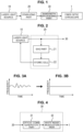
- FIG. 1 is a schematic block diagram for explaining the configuration of the light source device for a fiber optic gyroscope according to the present invention.
- the light source device for a fiber optic gyroscope according to the present invention is mainly constituted by a laser light source 10, a stabilizing part 20, and a bandwidth broadening part 30. That is, the light source device for a fiber optic gyroscope according to the present invention uses the stabilizing part 20 to stabilize the laser light from the laser light source 10, uses the bandwidth broadening part 30 to broaden the bandwidth of the laser light, and drives the fiber optic gyroscope 1.
- the laser light source 10 emits a laser light of a predetermined frequency.
- the laser light from the laser light source 10 may be a continuous wave (CW) light.
- CW continuous wave
- a semiconductor laser, a solid-state laser, a gas laser, and a dye laser, etc. are available as the laser light source 10.
- the wavelength of the laser light emitted from the laser light source 10 is not limited to a specific one. That is, the laser light source 10 may emit at least a laser light of a 1560 nm wavelength at which light propagation loss of the optical fiber is small or a 780 nm wavelength which is the second harmonic thereof.
- the laser light source of the light source device for a fiber optic gyroscope according to the present invention is not limited to a continuous wave laser light source and may be a pulse laser light source that emits a light of pulse-like spectra equally spaced at predetermined intervals.
- a specific example may be an optical comb light source.
- the stabilizing part 20 stabilizes a predetermined frequency (wavelength) of the laser light emitted from the laser light source 10.
- the stabilizing part 20 may lock the laser light emitted from the laser light source 10 to a reference frequency source for stabilization.
- the predetermined frequency is a 1560 nm wavelength
- the laser light may be stabilized with the stability of frequency in the order of kHz or MHz (up to about 0.001 ppm).
- the frequency spectral line width of the laser light is originally narrow to a certain degree, so that the stabilizing part 20 of the light source device for a fiber optic gyroscope according to the present invention may enhance the long-term frequency stability (i.e., relatively slow fluctuation) of the laser light. Therefore, it is not always necessary to reduce short-term phase noise and the like with high accuracy so as to narrow the frequency spectral line width.
- the configuration of the stabilizing part 20 will be described later more specifically.
- the bandwidth broadening part 30 makes the laser light stabilized by the stabilizing part 20 into a light having a continuous broadband spectrum.
- the bandwidth broadening part 30 may function to convert the laser light into, for example, light having a plurality of spectra continuously arranged with equally spaced at predetermined intervals with a predetermined frequency as a center. Specifically, when the predetermined frequency is a 1560 nm wavelength, a frequency band is broadened in THz order (nm order in wavelength).
- the resultant light is a light having continuous broadband spectrum obtained by conversion based on the stabilized laser light, and thus the center frequency (center wavelength) thereof is also stabilized. Accordingly, the scale factor is also stabilized.
- the configuration of the bandwidth broadening part 30 will be described later more specifically.
- the wavelength of the laser light is stabilized to thereby enhance the stability of the scale factor. Then, the laser light can be broadened in bandwidth with the stabilized scale factor, so that it is possible to avoid performance degradation due to such as light backscattering and polarization coupling in the fiber optic coil.
- FIG. 2 is a schematic block diagram for explaining a specific example of the stabilizing part of the light source device for a fiber optic gyroscope according to the present invention.
- FIG. 3 is graphs schematically illustrating a state where the frequency of the laser light is stabilized by the stabilizing part of the light source device for a fiber optic gyroscope according to the present invention; FIG. 3A illustrating frequency characteristics with respect to the time before stabilization, and FIG. 3B illustrating frequency characteristics with respect to the time after stabilization. As illustrated in FIG.
- the stabilizing part 20 serves as a feedback circuit for locking the laser light emitted from the laser light source 10 to a reference frequency source for stabilization.
- the illustrated feedback circuit uses a second harmonic generation (SHG) part 21 to convert the wavelength into 1/2 of the original frequency and then locks the resultant laser light to an atomic cell 22 as the reference frequency source, followed by feedback to the laser light source 10.
- the SHG part 21 may be a nonlinear crystal that converts the wavelength into, for example, 1/2 of the original frequency.
- the atomic cell 22 may be a cell enclosing a rubidium (Rb) atomic gas, when, for example, a wavelength of 780 nm is used.
- the laser light source 10 a semiconductor laser light source that outputs a continuous wave (CW) light of a 1560 nm wavelength is used as the laser light source 10.
- the frequency characteristics of the laser light from the semiconductor laser light source is illustrated in FIG. 3A .
- the laser light from the semiconductor laser light source relatively slowly fluctuates in frequency.
- the wavelength of this laser light is converted into 780 nm by the SHG part 21.
- the resultant laser light of 780 nm is made to pass through the atomic cell 22 enclosing the Rb atomic gas to be separated using various absorption spectroscopy methods such as linear absorption spectroscopy and saturated absorption spectroscopy.
- the spectra thus obtained are used to perform feedback to the semiconductor laser light source. This stabilizes the frequency of the laser light from the laser light source 10 by means of the Rb atoms of the atomic cell 22 as the reference frequency source. That is, as illustrated in FIG. 3B , long-term frequency stability is enhanced.
- the stabilizing part 20 of the light source device for a fiber optic gyroscope according to the present invention is not limited to the one that uses the above SHG and atomic spectroscopy.
- absorption lines for molecules such as C 2 H 2 and HCN exist around 1560 nm, so that it is also possible to stabilize the frequency of the laser light from the laser light source 10 by using a glass cell enclosing these molecular gases to separate the laser light of a 1560 nm wavelength according to various absorption spectroscopy methods such as linear absorption spectroscopy and saturated absorption spectroscopy. That is, the stabilizing part 20 may stabilize the frequency of the laser light by separating the laser light using one enclosing, in a glass cell, atoms or molecules for which the absorption lines exist in a desired frequency band as the reference frequency source.
- an optical resonator is applicable as the stabilizing part 20. That is a Fabry-Perot optical resonator constituted by two mutually facing mirrors. This optical resonator resonates with a light of a specific frequency, so that feedback is performed using the optical resonator as the reference frequency source to lock the frequency of the light.
- any existing or future type as long as it can stabilize a predetermined frequency of the inputted laser light are applicable as the stabilizing part 20 of the light source device for a fiber optic gyroscope according to the present invention.
- FIG. 4 is a schematic block diagram for explaining a specific example of the bandwidth broadening part of the light source device for a fiber optic gyroscope according to the present invention.
- FIG. 5 is graphs schematically illustrating the frequency spectrum of the laser light processed by the bandwidth broadening part of the light source device for a fiber optic gyroscope according to the present invention; FIG. 5A illustrating a frequency spectrum in an output from an optical comb generation part, and FIG. 5B illustrating a frequency spectrum in an output from a white noise modulation part.
- the bandwidth broadening part 30 makes the laser light stabilized by the stabilizing part 20 have a broadband spectrum and a continuous spectrum.
- the bandwidth broadening part 30 is constituted by an optical comb generation part 31 and a white noise modulation part 32.
- the optical comb generation part 31 is to which the laser light stabilized by the stabilizing part 20 is inputted, and emits a light having a plurality of spectra equally spaced at predetermined intervals with a predetermined frequency as a center. That is, when the stabilized laser light is inputted, the optical comb generation part 31 outputs light having a plurality of highly stable spectra equally spaced intervals on the left and right sides with a predetermined frequency as a center, as illustrated in FIG. 5A . Since the laser light stabilized in frequency is inputted, the spectra of the generated optical comb are also highly stabilized. Incidentally, any existing or future type as long as it can generate an optical comb are applicable as the optical comb generation part 31.
- the white noise modulation part 32 is to which the light emitted from the optical comb generation part 31 is inputted, and performs frequency modulation using white noise for making a continuous spectrum with a modulation width equal to or more than a predetermined interval of a plurality of spectra. That is, when an optical comb having stabilized spectra as illustrated in FIG. 5A is inputted, the white noise modulation part 32 performs frequency modulation with white noise so as to fill the interval between the plurality of spectra to obtain a continuous spectrum (uniform spectrum) as illustrated in FIG. 5B .
- the white noise modulation part 32 can generate a light of a continuous spectrum over a broad bandwidth.
- any existing or future type as long as it can perform frequency modulation using white noise are applicable as the white noise modulation part 32.
- the spectra of the optical comb are highly stabilized, and a predetermined frequency (wavelength) is kept stable.
- a predetermined frequency is a 1560 nm wavelength
- the laser light is stabilized with the stability of frequency in the order of kHz or MHz (up to about 0.001 ppm). As a result, the stability of the scale factor is enhanced.
- the stabilized laser light is spread by the optical comb such that a plurality of spectra is continuously arranged at even intervals over a broad bandwidth, and the plurality of spectra is made into a continuous spectrum by white noise, with the result that the light is broadened in bandwidth.
- the frequency of the laser light from the laser light source 10 is a 1560 nm wavelength, for example, the frequency band is broadened in the order of THz (nm order in wavelength).
- the light source device for a fiber optic gyroscope according to the present invention can improve the scale factor while preventing performance degradation due to such as light backscattering and polarization coupling in the fiber optic coil.
- FIG. 6 is a schematic block diagram for explaining another specific example of the bandwidth broadening part of the light source device for a fiber optic gyroscope according to the present invention.
- the same reference numerals as those in FIG. 4 denote the same parts.
- FIG. 7 is graphs schematically illustrating the frequency spectrum of the laser light processed by the bandwidth broadening part of the light source device for a fiber optic gyroscope according to the present invention; FIG. 7 Aillustrating a frequency spectrum in an output from the white noise modulation part, and FIG.
- frequency modulation is performed by the white noise modulation part 32 first, and then a plurality of spectrization is performed by the optical comb generation part 31. That is, the bandwidth broadening part 30 is constituted by the white noise modulation part 32 and optical comb generation part 31.
- the white noise modulation part 32 is to which the laser light stabilized by the stabilizing part 20 is inputted, and performs frequency modulation using white noise for making a continuous spectrum with a predetermined modulation width.
- the white noise modulation part 32 performs frequency modulation using white noise for making a continuous spectrum as illustrated in FIG. 7A with a predetermined modulation width thereby achieving a continuous spectrum (uniform spectrum) having a predetermined modulation width.
- the optical comb generation part 31 is to which the light emitted from the white noise modulation part 32 is inputted, and emits a light having a plurality of spectra equally spaced at predetermined intervals that is equal to or less than a predetermined modulation width by using white noise, with a predetermined frequency as a center. That is, when the laser light having a continuous spectrum with a predetermined modulation width as illustrated in FIG. 7A is inputted, the optical comb generation part 31 outputs light having a plurality of spectra equally spaced intervals on the left and right sides with a predetermined frequency of the inputted laser light as a center, as illustrated in FIG. 7B . As a result, as in the example illustrated in FIG. 4 , it is possible to generate light of a continuous spectrum over a broad bandwidth.
- FIG. 8 is a schematic block diagram for explaining another example of the light source device for a fiber optic gyroscope according to the present invention.
- the illustrated bandwidth broadening part 30 is constituted by a parametric down-conversion part 33.
- the parametric down-conversion part 33 uses a nonlinear optical crystal and emits a photon pair using the laser light stabilized by the stabilizing part 20 as excitation light.
- the output frequency of the light source device for a fiber optic gyroscope according to the present invention is set to 1560 nm at which the propagation loss of an optical fiber is small.
- the laser light source 10 a semiconductor laser that can emit a laser light of 780 nm is used.
- the stabilizing part 20 may perform feedback using only the atomic cell 22. That is, an absorption spectroscopy method, etc. is used to lock the 780 nm light to the atomic cell 22 enclosing an Rb atomic gas, and the obtained spectrum is used to perform feedback to the semiconductor laser.
- the thus stabilized laser light is inputted to the parametric down-conversion part 33.
- the parametric down-conversion part 33 generates a photon pair with the stabilized laser light as excitation light. That is, the laser light inputted to the parametric down-conversion part 33 has a continuous spectrum (uniform spectrum) spreading to the left and right with 1/2 frequency (twice in wavelength) of a predetermined frequency of the inputted laser light. Specifically, when a light of stabilized wavelength of 780 nm is inputted to the parametric down-conversion part 33, the frequency band of the laser light of 1560 nm wavelength is broadened in the order of THz (nm order in wavelength). This allows light having a continuous broadband spectrum to be obtained.
- the laser light source 10 may be a continuous laser light source that emits a continuous light and may alternatively be a pulse laser light source that emits a light of pulse-like spectra equally spaced at predetermined intervals.
- a pulse laser light is locked to a predetermined frequency by the stabilizing part 20 for stabilization, whereby the pulse-like spectra are each stabilized.
- the bandwidth broadening part 30 is not limited to the parametric down-conversion part 33 illustrated in FIG. 8 . That is, in place of the parametric down-conversion part 33, the white noise modulation part 32 may be used as the bandwidth broadening part 30.
- the pulse-like spectra equally spaced at predetermined intervals from the pulse laser light source are stabilized by the stabilizing part 20 and inputted to the white noise modulation part 32.
- the white noise modulation part 32 uses white noise to perform frequency modulation with a modulation width equal to or more than a predetermined interval of pulse-like spectra to obtain a continuous spectrum (uniform spectrum).
- FIG. 9 is a schematic block diagram for explaining still another example of the light source device for a fiber optic gyroscope according to the present invention.
- the illustrated bandwidth broadening part 30 is constituted by the optical comb generation part 31 and parametric down-conversion part 33. That is, the bandwidth broadening part 30 has a configuration combining the optical comb generation part 31 illustrated in FIG. 4 and the parametric down-conversion part 33 illustrated in FIG. 8 .
- the output frequency of the light source device for a fiber optic gyroscope according to the present invention is 1560 nm at which the propagation loss of an optical fiber is small.
- the laser light source 10 a semiconductor laser that can emit a laser light of 780 nm is used.
- the stabilizing part 20 may perform feedback using only the atomic cell 22. That is, an absorption spectroscopy method, etc. is used to lock the light of 780 nm of the laser light source 10 to the atomic cell 22 enclosing an Rb atomic gas, and the obtained spectrum is used to perform feedback to the semiconductor laser.
- the thus stabilized laser light is inputted to the optical comb generation part 31.
- the optical comb generation part 31 emits a light having a plurality of spectra equally spaced intervals on the left and right sides with a predetermined frequency of the inputted stabilized laser light as a center. Then, the light of a plurality of spectra equally spaced intervals is inputted to the parametric down-conversion part 33, and the parametric down-conversion part 33 generates a photon pair with the stabilized laser light as excitation light. That is, the laser light inputted to the parametric down-conversion part 33 has a continuous spectrum (uniform spectrum) spreading to the left and right with 1/2 frequency (twice in wavelength) of a predetermined frequency of the inputted laser light.
- the frequency band of the laser light of 1560 nm wavelength is broadened in the order of THz (nm order in wavelength). This allows light having a continuous broadband spectrum to be obtained.
- the light is pulsed by the optical comb generation part 31, so that conversion efficiency by the parametric down-conversion part 33 is enhanced as compared to the example illustrated in FIG. 8 .
- a fiber optic gyroscope suitable for the light source device for a fiber optic gyroscope according to the present invention is not limited in use only to a specific fiber optic gyroscope but is versatile. However, when being used in combination of a fiber optic gyroscope to be described below, intensity noise associated with broadening of bandwidth can be reduced. In addition, thermal phase noise caused by heat of a fiber optic coil can be reduced.
- light from a light source can be broadened in bandwidth, thereby allowing enhancement of stability of the scale factor.
- broadening of bandwidth may cause intensity noise due to mutual interference between lights of different frequencies. This noise is referred to as "RIN (Relative Intensity Noise)".
- the light source device for a fiber optic gyroscope according to the present invention can be applied to a fiber optic gyroscope having a configuration that can reduce RIN.
- the optical fiber of the fiber optic coil is formed of quartz, and the atoms constituting quartz are in thermal motion at room temperature.
- the thermal motion of the atoms causes a variation in the refractive index of the optical fiber, so that phase noise is superimposed on the light that has passed through the fiber optic coil. This noise is referred to as "Thermal Phase Noise”.
- the thermal phase noise has a property of being reduced when being subjected to phase modulation at integral multiples of an eigenfrequency of the fiber optic coil.
- the thermal phase noise can be reduced.
- FIG. 10 is a schematic block diagram for explaining the configuration of a fiber optic gyroscope suitably using the light source device for a fiber optic gyroscope according to the present invention.
- the same reference numerals as those in FIG. 1 , etc. denote the same parts.
- the fiber optic gyroscope in the illustrated example can reduce the thermal phase noise.
- a fiber optic gyroscope 1 uses, as a light source, the above-described light source device (10, 20, 30) for a fiber optic gyroscope according to the present invention.
- the fiber optic gyroscope 1 is driven by using a light having a continuous broadband spectrum generated by the light source device for a fiber optic gyroscope according to the present invention.
- the fiber optic gyroscope 1 is mainly constituted by an optical circulator 40, a multifunctional integrated optical circuit 50, a phase modulation signal generator 60, an optical detector 70, and a synchronous detector 80.
- the multifunctional integrated optical circuit 50 is connected with a fiber optic coil 2.
- the optical circulator 40 separates between the light having a continuous broadband spectrum from the bandwidth broadening part 30 and an interference light obtained by recombining a counterclockwise light and a clockwise light that have passed through the fiber optic coil 2. That is, the optical circulator 40 outputs the light from the bandwidth broadening part 30 to the multifunctional integrated optical circuit 50 to be described later and outputs the interference light returned thereto to the optical detector 70.
- the light having a continuous broadband spectrum from the bandwidth broadening part 30 enters the optical circulator 40 from the left side thereof and is outputted from the right side thereof.
- the returned interference light obtained by recombining the counterclockwise light and clockwise light that have passed through the fiber optic coil 2 enters the optical circulator 40 from the right side thereof and is outputted downward therefrom to the optical detector 70 to be described later.
- the multifunctional integrated optical circuit 50 is constituted by a polarizer 51, a Y-branch/recombiner 52, a first phase modulator 53, and a second phase modulator 54.
- the polarizer 51 receives the light having a continuous broadband spectrum from the bandwidth broadening part 30 through the optical circulator 40. Then, the polarizer 51 allows a single polarized light to pass therethrough.
- the Y-branch/recombiner 52 branches the light, i.e., the single polarized light, from the polarizer 51 and makes the resultant lights enter both ends of the fiber optic coil 2. The lights entering the both ends of the fiber optic coil 2 become the counterclockwise light and clockwise light, respectively.
- the Y-branch/recombiner 52 recombines the counterclockwise light and clockwise light that have passed through the fiber optic coil 2 and outputs the resultant light to the optical circulator 40 as an interference light.
- the first phase modulator 53 modulates one of the incident lights which enters one end of the fiber optic coil 2. For example, the light which becomes the clockwise light may be modulated.
- the second phase modulator 54 modulates the other of the incident lights which enters the other end of the fiber optic coil 2. For example, the light which becomes the counterclockwise light light may be modulated.
- the phase modulation signal generator 60 is configured to generate a phase modulation signal so as to reduce thermal phase noise.
- the phase modulation signal generator 60 outputs the phase modulation signal to the first phase modulator 53 and second phase modulator 54 of the multifunctional integrated optical circuit 50.
- the phase modulation signal generator 60 generates the phase modulation signal for the multifunctional integrated optical circuit 50 so as to perform phase modulation at integral multiples of the eigenfrequency of the fiber optic coil 2. Specifically, the phase modulation may be performed to be at integral multiples of about 10 to 100 times of the eigenfrequency. This can reduce thermal phase noise.
- the optical detector 70 to which the interference light recombining the counterclockwise light and clockwise light that have passed through the fiber optic coil 2 from the optical circulator 40 is entered, detects the light intensity signal of the interference light.
- the synchronous detector 80 uses the phase modulation signal from the phase modulation signal generator 60 as a reference signal to synchronously detect the light intensity signal detected by the optical detector 70 and outputs the detected light intensity signal as a detection signal of input angular velocity to the fiber optic coil 2.
- the thus configured fiber optic gyroscope using the light source device for a fiber optic gyroscope according to the present invention performs phase modulation at integral multiples of the eigenfrequency of the fiber optic coil 2 to thereby make it possible to reduce thermal phase noise.
- FIG. 11 is a schematic block diagram for explaining the configuration of a fiber optic gyroscope suitably using the light source device for a fiber optic gyroscope according to the present invention.
- the same reference numerals as those in FIG. 10 denote the same parts, and overlapping description will be omitted.
- the fiber optic gyroscope in the illustrated example can reduce relative intensity noise (RIN).
- the fiber optic gyroscope 1 in this example is driven by using a light having a continuous broadband spectrum generated by the light source device (10, 20, 30) for a fiber optic gyroscope according to the present invention.
- the fiber optic gyroscope 1 is mainly constituted by the optical circulator 40, multifunctional integrated optical circuit 50, a phase modulation signal generator 61, optical detector 70, a synchronous detector 81, and a reference light detector 90.
- the light having a continuous broadband spectrum from the bandwidth broadening part 30 may be separated by a beam splitter 45 or the like for also outputting to the reference light detector 90 to be described later apart from a light to be directed to the optical circulator 40.
- the phase modulation signal generator 61 is configured to generate a phase modulation signal so as to reduce relative intensity noise.
- the phase modulation signal generator 61 outputs the phase modulation signal to the first phase modulator 52 and second phase modulator 54 of the multifunctional integrated optical circuit 50.
- the phase modulation signal generator 61 generates the phase modulation signal for the multifunctional integrated optical circuit 50 so as to perform phase modulation at odd multiples of the eigenfrequency of the fiber optic coil 2. Specifically, the phase modulation may be performed to be at odd multiples of one time, three times, five times, etc. of the eigenfrequency. This can reduce relative intensity noise.
- the reference light detector 90 detects a reference light intensity signal of the light having a continuous broadband spectrum from the bandwidth broadening part 30. That is, the reference light detector 90 uses the light having a continuous broadband spectrum from the bandwidth broadening part 30 as a reference light to detect the reference light intensity signal thereof.
- the synchronous detector 81 uses the phase modulation signal from the phase modulation signal generator 61 as a reference signal to synchronously detect a sum signal of the light intensity signal detected by the optical detector 70 and the reference light intensity signal detected by the reference light detector 90 and outputs the detected sum signal as a detection signal of input angular velocity to the fiber optic coil 2.
- the thus configured fiber optic gyroscope using the light source device for a fiber optic gyroscope according to the present invention performs phase modulation at odd multiples of the eigenfrequency of the fiber optic coil 2 to thereby make it possible to reduce relative intensity noise. Further, when phase modulation is performed at odd multiples and integral multiples of the eigenfrequency, it is possible to reduce thermal phase noise in addition to the relative intensity noise.
- the phase modulation is performed at odd multiples, and the sum signal of the light intensity signal detected by the optical detector 70 and the reference light intensity signal detected by the reference light detector 90 is synchronously detected; alternatively, in place of this, a configuration may be possible, in which the phase modulation is performed at even multiples, and a difference signal between the light intensity signal detected by the optical detector 70 and the reference light intensity signal detected by the reference light detector 90 is synchronously detected. That is, the phase modulation signal generator 61 may generate the phase modulation signal for the multifunctional integrated optical circuit 50 so as to perform the phase modulation at even multiples of the eigenfrequency of the fiber optic coil 2. Accordingly, the synchronous detector 81 may synchronously detect the difference signal between the light intensity signal detected by the optical detector 70 and the reference light intensity signal detected by the reference light detector 90.
- the synchronous detector 80 illustrated in FIG. 10 or the synchronous detector 81 illustrated in FIG. 11 may use the phase modulation signal from the phase modulation signal generator 60 (61) as a reference signal to perform the synchronous detection. Further, a signal for canceling a phase difference between the counterclockwise light and the clockwise light generated by input angular velocity to the fiber optic coil 2 can be output to the phase modulation signal generator 60 (61) as a feedback control signal for feedback control of the phase modulation signal generator 60 (61). This can increase the dynamic range of the input angular velocity.
- the light source device for a fiber optic gyroscope according to the present invention and the fiber optic gyroscope using the same are not limited to the illustrated examples but may be variously modified within the scope of the present invention as defined by the appended claims.
Landscapes
- Physics & Mathematics (AREA)
- Nonlinear Science (AREA)
- Optics & Photonics (AREA)
- General Physics & Mathematics (AREA)
- Electromagnetism (AREA)
- Engineering & Computer Science (AREA)
- Power Engineering (AREA)
- Radar, Positioning & Navigation (AREA)
- Remote Sensing (AREA)
- Plasma & Fusion (AREA)
- Condensed Matter Physics & Semiconductors (AREA)
- Gyroscopes (AREA)
- Optical Modulation, Optical Deflection, Nonlinear Optics, Optical Demodulation, Optical Logic Elements (AREA)
Applications Claiming Priority (2)
| Application Number | Priority Date | Filing Date | Title |
|---|---|---|---|
| JP2019230925 | 2019-12-20 | ||
| PCT/JP2020/043273 WO2021124790A1 (ja) | 2019-12-20 | 2020-11-19 | 光ファイバジャイロスコープ用光源装置及びそれを用いた光ファイバジャイロスコープ |
Publications (3)
| Publication Number | Publication Date |
|---|---|
| EP4080163A1 EP4080163A1 (en) | 2022-10-26 |
| EP4080163A4 EP4080163A4 (en) | 2024-04-10 |
| EP4080163B1 true EP4080163B1 (en) | 2025-06-11 |
Family
ID=76477220
Family Applications (1)
| Application Number | Title | Priority Date | Filing Date |
|---|---|---|---|
| EP20902358.9A Active EP4080163B1 (en) | 2019-12-20 | 2020-11-19 | Light source device for optical fiber gyroscope |
Country Status (5)
| Country | Link |
|---|---|
| US (1) | US12266900B2 (https=) |
| EP (1) | EP4080163B1 (https=) |
| JP (1) | JP7296151B2 (https=) |
| AU (1) | AU2020408508B2 (https=) |
| WO (1) | WO2021124790A1 (https=) |
Families Citing this family (4)
| Publication number | Priority date | Publication date | Assignee | Title |
|---|---|---|---|---|
| WO2024024032A1 (ja) * | 2022-07-28 | 2024-02-01 | 国立大学法人東京工業大学 | 光ファイバジャイロスコープ用光源装置 |
| US20260009644A1 (en) | 2022-10-07 | 2026-01-08 | Institute Of Science Tokyo | Phase modulation signal generating device for fiber-optic gyroscope |
| US12535320B2 (en) | 2023-05-11 | 2026-01-27 | Honeywell International Inc. | Resonant optical gyroscope with a broadband light source and RIN reduction techniques |
| US12546603B2 (en) | 2023-07-21 | 2026-02-10 | Honeywell International Inc. | Optical gyroscope with broadband comb interrogation |
Family Cites Families (15)
| Publication number | Priority date | Publication date | Assignee | Title |
|---|---|---|---|---|
| GB8921460D0 (en) | 1989-09-22 | 1990-05-30 | British Aerospace | Electronic compensation in ring laser gyros |
| JPH07324938A (ja) | 1994-05-31 | 1995-12-12 | Tokimec Inc | 光ファイバジャイロ |
| JP2005172651A (ja) | 2003-12-12 | 2005-06-30 | Nippon Telegr & Teleph Corp <Ntt> | 光ジャイロ |
| GB2449290B (en) | 2007-05-17 | 2010-09-22 | Toshiba Res Europ Ltd | An optical system |
| US8514400B2 (en) * | 2010-03-23 | 2013-08-20 | Oewaves, Inc. | Optical gyroscope sensors based on optical whispering gallery mode resonators |
| US9354064B2 (en) | 2014-07-07 | 2016-05-31 | Honeywell International Inc. | Resonator fiber optic gyroscope employing common cavity length modulation along with high bandwidth laser stabilization |
| JP2016017952A (ja) * | 2014-07-11 | 2016-02-01 | 株式会社東芝 | 超音波流量計 |
| US10741989B2 (en) * | 2015-01-23 | 2020-08-11 | Arizona Board Of Regents On Behalf Of The University Of Arizona | All-fiber bidirectional synchronously pumped ultrafast ring oscillator for precision sensing |
| FR3052859B1 (fr) | 2016-06-20 | 2018-11-23 | Ixblue | Systeme de mesure et gyrometre comportant un tel systeme |
| GB201611046D0 (en) | 2016-06-24 | 2016-08-10 | Npl Man Ltd | Optical resonator systems |
| WO2018057468A1 (en) | 2016-09-20 | 2018-03-29 | The Board Of Trustees Of The Leland Stanford Junior University | Optical system and method utilizing a laser-driven light source with white noise modulation |
| WO2019191647A1 (en) * | 2018-03-29 | 2019-10-03 | The Trustees Of Columbia University In The City Of New York | Fully integrated chip platform for electrically pumped frequency comb generation |
| US10337867B1 (en) | 2018-04-13 | 2019-07-02 | Northrop Grumman Systems Corporation | Symmetrical wavelength multiplexor for fiber optic gyro source |
| US11011882B2 (en) * | 2018-09-05 | 2021-05-18 | Government Of The United States Of America, As Represented By The Secretary Of Commerce | Ultrafast electro-optic laser |
| US11681200B2 (en) * | 2019-05-10 | 2023-06-20 | Purdue Research Foundation | Optical quantum logic for use in large operational spaces |
-
2020
- 2020-11-19 AU AU2020408508A patent/AU2020408508B2/en active Active
- 2020-11-19 WO PCT/JP2020/043273 patent/WO2021124790A1/ja not_active Ceased
- 2020-11-19 EP EP20902358.9A patent/EP4080163B1/en active Active
- 2020-11-19 JP JP2021565392A patent/JP7296151B2/ja active Active
- 2020-11-19 US US17/786,646 patent/US12266900B2/en active Active
Also Published As
| Publication number | Publication date |
|---|---|
| US12266900B2 (en) | 2025-04-01 |
| EP4080163A1 (en) | 2022-10-26 |
| JP7296151B2 (ja) | 2023-06-22 |
| AU2020408508B2 (en) | 2023-09-21 |
| JPWO2021124790A1 (https=) | 2021-06-24 |
| WO2021124790A1 (ja) | 2021-06-24 |
| EP4080163A4 (en) | 2024-04-10 |
| AU2020408508A1 (en) | 2022-07-28 |
| US20230030335A1 (en) | 2023-02-02 |
Similar Documents
| Publication | Publication Date | Title |
|---|---|---|
| EP4080163B1 (en) | Light source device for optical fiber gyroscope | |
| US8514400B2 (en) | Optical gyroscope sensors based on optical whispering gallery mode resonators | |
| JP5096858B2 (ja) | 光学式共振器ジャイロスコープ、および共振非対称誤差を低減するための方法 | |
| US8237514B2 (en) | Quantum interference device, atomic oscillator, and magnetic sensor | |
| EP2650644B1 (en) | Resonator fiber optic gyroscope utilizing laser frequency combs | |
| JP6445468B2 (ja) | リング共振器を備えた光ファイバ干渉計測装置、かかる装置を含むジャイロメータ及び慣性姿勢又は航法ユニット | |
| EP1857779B1 (en) | Integrated optical rotation rate sensor and method for sensing rotation rate | |
| EP3048420A1 (en) | Systems and methods for an optical frequency comb stimulated brillouin scattering gyroscope with rigid optical waveguide resonator | |
| EP3875903B1 (en) | Bidirectional optical-carrying microwave resonance system based on circulator structure and method for detecting angular velocity by said system | |
| US7362443B2 (en) | Optical gyro with free space resonator and method for sensing inertial rotation rate | |
| EP3999837B1 (en) | Chirped laser dispersion spectrometer and method | |
| US20120050745A1 (en) | Resonator fiber optic gyroscopes with reduced rotation rate instability from back reflections | |
| US11378401B2 (en) | Polarization-maintaining fully-reciprocal bi-directional optical carrier microwave resonance system and angular velocity measurement method thereof | |
| US11920933B2 (en) | Optical gyroscope with a resonator having bias error reduction | |
| EP4600607A1 (en) | Phase modulation signal generating device for fiber-optic gyroscope | |
| US9267799B2 (en) | Method and apparatus of monitoring and tracking optical frequency differences of modulated beams | |
| US12618674B2 (en) | Interferometric resonator optical gyroscope with optical frequency comb | |
| US20250093158A1 (en) | Interferometric resonator optical gyroscope with optical frequency comb | |
| JPH06235641A (ja) | 光ファイバジャイロスコープ | |
| CN119309560A (zh) | 具有双宽带光源的谐振式光学陀螺仪 | |
| JPH09318366A (ja) | 波長モニタ装置及び光ファイバジャイロ |
Legal Events
| Date | Code | Title | Description |
|---|---|---|---|
| STAA | Information on the status of an ep patent application or granted ep patent |
Free format text: STATUS: THE INTERNATIONAL PUBLICATION HAS BEEN MADE |
|
| PUAI | Public reference made under article 153(3) epc to a published international application that has entered the european phase |
Free format text: ORIGINAL CODE: 0009012 |
|
| STAA | Information on the status of an ep patent application or granted ep patent |
Free format text: STATUS: REQUEST FOR EXAMINATION WAS MADE |
|
| 17P | Request for examination filed |
Effective date: 20220622 |
|
| AK | Designated contracting states |
Kind code of ref document: A1 Designated state(s): AL AT BE BG CH CY CZ DE DK EE ES FI FR GB GR HR HU IE IS IT LI LT LU LV MC MK MT NL NO PL PT RO RS SE SI SK SM TR |
|
| DAV | Request for validation of the european patent (deleted) | ||
| DAX | Request for extension of the european patent (deleted) | ||
| RIC1 | Information provided on ipc code assigned before grant |
Ipc: H01S 5/0687 20060101ALI20231208BHEP Ipc: H01S 5/00 20060101ALI20231208BHEP Ipc: H01S 3/137 20060101ALI20231208BHEP Ipc: H01S 3/00 20060101ALI20231208BHEP Ipc: G02F 1/39 20060101ALI20231208BHEP Ipc: G02F 1/37 20060101ALI20231208BHEP Ipc: G01C 19/72 20060101AFI20231208BHEP |
|
| A4 | Supplementary search report drawn up and despatched |
Effective date: 20240307 |
|
| RIC1 | Information provided on ipc code assigned before grant |
Ipc: H01S 5/0687 20060101ALI20240301BHEP Ipc: H01S 5/00 20060101ALI20240301BHEP Ipc: H01S 3/137 20060101ALI20240301BHEP Ipc: H01S 3/00 20060101ALI20240301BHEP Ipc: G02F 1/39 20060101ALI20240301BHEP Ipc: G02F 1/37 20060101ALI20240301BHEP Ipc: G01C 19/72 20060101AFI20240301BHEP |
|
| GRAP | Despatch of communication of intention to grant a patent |
Free format text: ORIGINAL CODE: EPIDOSNIGR1 |
|
| STAA | Information on the status of an ep patent application or granted ep patent |
Free format text: STATUS: GRANT OF PATENT IS INTENDED |
|
| INTG | Intention to grant announced |
Effective date: 20250116 |
|
| RAP3 | Party data changed (applicant data changed or rights of an application transferred) |
Owner name: INSTITUTE OF SCIENCE TOKYO |
|
| P01 | Opt-out of the competence of the unified patent court (upc) registered |
Free format text: CASE NUMBER: APP_15931/2025 Effective date: 20250401 |
|
| GRAS | Grant fee paid |
Free format text: ORIGINAL CODE: EPIDOSNIGR3 |
|
| GRAA | (expected) grant |
Free format text: ORIGINAL CODE: 0009210 |
|
| STAA | Information on the status of an ep patent application or granted ep patent |
Free format text: STATUS: THE PATENT HAS BEEN GRANTED |
|
| AK | Designated contracting states |
Kind code of ref document: B1 Designated state(s): AL AT BE BG CH CY CZ DE DK EE ES FI FR GB GR HR HU IE IS IT LI LT LU LV MC MK MT NL NO PL PT RO RS SE SI SK SM TR |
|
| REG | Reference to a national code |
Ref country code: GB Ref legal event code: FG4D |
|
| REG | Reference to a national code |
Ref country code: CH Ref legal event code: EP |
|
| REG | Reference to a national code |
Ref country code: IE Ref legal event code: FG4D |
|
| REG | Reference to a national code |
Ref country code: DE Ref legal event code: R096 Ref document number: 602020052758 Country of ref document: DE |
|
| PG25 | Lapsed in a contracting state [announced via postgrant information from national office to epo] |
Ref country code: ES Free format text: LAPSE BECAUSE OF FAILURE TO SUBMIT A TRANSLATION OF THE DESCRIPTION OR TO PAY THE FEE WITHIN THE PRESCRIBED TIME-LIMIT Effective date: 20250611 Ref country code: FI Free format text: LAPSE BECAUSE OF FAILURE TO SUBMIT A TRANSLATION OF THE DESCRIPTION OR TO PAY THE FEE WITHIN THE PRESCRIBED TIME-LIMIT Effective date: 20250611 |
|
| REG | Reference to a national code |
Ref country code: LT Ref legal event code: MG9D |
|
| PG25 | Lapsed in a contracting state [announced via postgrant information from national office to epo] |
Ref country code: NO Free format text: LAPSE BECAUSE OF FAILURE TO SUBMIT A TRANSLATION OF THE DESCRIPTION OR TO PAY THE FEE WITHIN THE PRESCRIBED TIME-LIMIT Effective date: 20250911 Ref country code: GR Free format text: LAPSE BECAUSE OF FAILURE TO SUBMIT A TRANSLATION OF THE DESCRIPTION OR TO PAY THE FEE WITHIN THE PRESCRIBED TIME-LIMIT Effective date: 20250912 |
|
| REG | Reference to a national code |
Ref country code: NL Ref legal event code: MP Effective date: 20250611 |
|
| PG25 | Lapsed in a contracting state [announced via postgrant information from national office to epo] |
Ref country code: BG Free format text: LAPSE BECAUSE OF FAILURE TO SUBMIT A TRANSLATION OF THE DESCRIPTION OR TO PAY THE FEE WITHIN THE PRESCRIBED TIME-LIMIT Effective date: 20250611 |
|
| PGFP | Annual fee paid to national office [announced via postgrant information from national office to epo] |
Ref country code: GB Payment date: 20250925 Year of fee payment: 6 |
|
| PG25 | Lapsed in a contracting state [announced via postgrant information from national office to epo] |
Ref country code: HR Free format text: LAPSE BECAUSE OF FAILURE TO SUBMIT A TRANSLATION OF THE DESCRIPTION OR TO PAY THE FEE WITHIN THE PRESCRIBED TIME-LIMIT Effective date: 20250611 |
|
| PGFP | Annual fee paid to national office [announced via postgrant information from national office to epo] |
Ref country code: FR Payment date: 20250908 Year of fee payment: 6 |
|
| PG25 | Lapsed in a contracting state [announced via postgrant information from national office to epo] |
Ref country code: RS Free format text: LAPSE BECAUSE OF FAILURE TO SUBMIT A TRANSLATION OF THE DESCRIPTION OR TO PAY THE FEE WITHIN THE PRESCRIBED TIME-LIMIT Effective date: 20250911 |
|
| PG25 | Lapsed in a contracting state [announced via postgrant information from national office to epo] |
Ref country code: LV Free format text: LAPSE BECAUSE OF FAILURE TO SUBMIT A TRANSLATION OF THE DESCRIPTION OR TO PAY THE FEE WITHIN THE PRESCRIBED TIME-LIMIT Effective date: 20250611 |
|
| PG25 | Lapsed in a contracting state [announced via postgrant information from national office to epo] |
Ref country code: NL Free format text: LAPSE BECAUSE OF FAILURE TO SUBMIT A TRANSLATION OF THE DESCRIPTION OR TO PAY THE FEE WITHIN THE PRESCRIBED TIME-LIMIT Effective date: 20250611 |
|
| PG25 | Lapsed in a contracting state [announced via postgrant information from national office to epo] |
Ref country code: PT Free format text: LAPSE BECAUSE OF FAILURE TO SUBMIT A TRANSLATION OF THE DESCRIPTION OR TO PAY THE FEE WITHIN THE PRESCRIBED TIME-LIMIT Effective date: 20251013 |
|
| REG | Reference to a national code |
Ref country code: AT Ref legal event code: MK05 Ref document number: 1802576 Country of ref document: AT Kind code of ref document: T Effective date: 20250611 |
|
| PG25 | Lapsed in a contracting state [announced via postgrant information from national office to epo] |
Ref country code: IS Free format text: LAPSE BECAUSE OF FAILURE TO SUBMIT A TRANSLATION OF THE DESCRIPTION OR TO PAY THE FEE WITHIN THE PRESCRIBED TIME-LIMIT Effective date: 20251011 |
|
| PGFP | Annual fee paid to national office [announced via postgrant information from national office to epo] |
Ref country code: DE Payment date: 20250923 Year of fee payment: 6 |
|
| PG25 | Lapsed in a contracting state [announced via postgrant information from national office to epo] |
Ref country code: AT Free format text: LAPSE BECAUSE OF FAILURE TO SUBMIT A TRANSLATION OF THE DESCRIPTION OR TO PAY THE FEE WITHIN THE PRESCRIBED TIME-LIMIT Effective date: 20250611 Ref country code: SM Free format text: LAPSE BECAUSE OF FAILURE TO SUBMIT A TRANSLATION OF THE DESCRIPTION OR TO PAY THE FEE WITHIN THE PRESCRIBED TIME-LIMIT Effective date: 20250611 |
|
| PG25 | Lapsed in a contracting state [announced via postgrant information from national office to epo] |
Ref country code: CZ Free format text: LAPSE BECAUSE OF FAILURE TO SUBMIT A TRANSLATION OF THE DESCRIPTION OR TO PAY THE FEE WITHIN THE PRESCRIBED TIME-LIMIT Effective date: 20250611 |
|
| PG25 | Lapsed in a contracting state [announced via postgrant information from national office to epo] |
Ref country code: PL Free format text: LAPSE BECAUSE OF FAILURE TO SUBMIT A TRANSLATION OF THE DESCRIPTION OR TO PAY THE FEE WITHIN THE PRESCRIBED TIME-LIMIT Effective date: 20250611 |
|
| PG25 | Lapsed in a contracting state [announced via postgrant information from national office to epo] |
Ref country code: EE Free format text: LAPSE BECAUSE OF FAILURE TO SUBMIT A TRANSLATION OF THE DESCRIPTION OR TO PAY THE FEE WITHIN THE PRESCRIBED TIME-LIMIT Effective date: 20250611 |
|
| PG25 | Lapsed in a contracting state [announced via postgrant information from national office to epo] |
Ref country code: SK Free format text: LAPSE BECAUSE OF FAILURE TO SUBMIT A TRANSLATION OF THE DESCRIPTION OR TO PAY THE FEE WITHIN THE PRESCRIBED TIME-LIMIT Effective date: 20250611 |
|
| PG25 | Lapsed in a contracting state [announced via postgrant information from national office to epo] |
Ref country code: RO Free format text: LAPSE BECAUSE OF FAILURE TO SUBMIT A TRANSLATION OF THE DESCRIPTION OR TO PAY THE FEE WITHIN THE PRESCRIBED TIME-LIMIT Effective date: 20250611 |
|
| REG | Reference to a national code |
Ref country code: DE Ref legal event code: R097 Ref document number: 602020052758 Country of ref document: DE |
|
| PG25 | Lapsed in a contracting state [announced via postgrant information from national office to epo] |
Ref country code: DK Free format text: LAPSE BECAUSE OF FAILURE TO SUBMIT A TRANSLATION OF THE DESCRIPTION OR TO PAY THE FEE WITHIN THE PRESCRIBED TIME-LIMIT Effective date: 20250611 |
|
| PG25 | Lapsed in a contracting state [announced via postgrant information from national office to epo] |
Ref country code: IT Free format text: LAPSE BECAUSE OF FAILURE TO SUBMIT A TRANSLATION OF THE DESCRIPTION OR TO PAY THE FEE WITHIN THE PRESCRIBED TIME-LIMIT Effective date: 20250611 |
|
| PLBE | No opposition filed within time limit |
Free format text: ORIGINAL CODE: 0009261 |
|
| STAA | Information on the status of an ep patent application or granted ep patent |
Free format text: STATUS: NO OPPOSITION FILED WITHIN TIME LIMIT |
|
| REG | Reference to a national code |
Ref country code: CH Ref legal event code: L10 Free format text: ST27 STATUS EVENT CODE: U-0-0-L10-L00 (AS PROVIDED BY THE NATIONAL OFFICE) Effective date: 20260423 |