EP4080048B1 - Drucklufterzeugungssystem - Google Patents
Drucklufterzeugungssystem Download PDFInfo
- Publication number
- EP4080048B1 EP4080048B1 EP22169497.9A EP22169497A EP4080048B1 EP 4080048 B1 EP4080048 B1 EP 4080048B1 EP 22169497 A EP22169497 A EP 22169497A EP 4080048 B1 EP4080048 B1 EP 4080048B1
- Authority
- EP
- European Patent Office
- Prior art keywords
- compressed air
- compression stage
- reciprocating compression
- generation system
- reciprocating
- Prior art date
- Legal status (The legal status is an assumption and is not a legal conclusion. Google has not performed a legal analysis and makes no representation as to the accuracy of the status listed.)
- Active
Links
Images

Classifications
-
- F—MECHANICAL ENGINEERING; LIGHTING; HEATING; WEAPONS; BLASTING
- F04—POSITIVE - DISPLACEMENT MACHINES FOR LIQUIDS; PUMPS FOR LIQUIDS OR ELASTIC FLUIDS
- F04B—POSITIVE-DISPLACEMENT MACHINES FOR LIQUIDS; PUMPS
- F04B37/00—Pumps having pertinent characteristics not provided for in, or of interest apart from, groups F04B25/00 - F04B35/00
- F04B37/10—Pumps having pertinent characteristics not provided for in, or of interest apart from, groups F04B25/00 - F04B35/00 for special use
- F04B37/12—Pumps having pertinent characteristics not provided for in, or of interest apart from, groups F04B25/00 - F04B35/00 for special use to obtain high pressure
-
- F—MECHANICAL ENGINEERING; LIGHTING; HEATING; WEAPONS; BLASTING
- F04—POSITIVE - DISPLACEMENT MACHINES FOR LIQUIDS; PUMPS FOR LIQUIDS OR ELASTIC FLUIDS
- F04B—POSITIVE-DISPLACEMENT MACHINES FOR LIQUIDS; PUMPS
- F04B25/00—Multi-stage pumps
-
- F—MECHANICAL ENGINEERING; LIGHTING; HEATING; WEAPONS; BLASTING
- F04—POSITIVE - DISPLACEMENT MACHINES FOR LIQUIDS; PUMPS FOR LIQUIDS OR ELASTIC FLUIDS
- F04B—POSITIVE-DISPLACEMENT MACHINES FOR LIQUIDS; PUMPS
- F04B39/00—Component parts, details, or accessories, of pumps or pumping systems specially adapted for elastic fluids, not otherwise provided for in, or of interest apart from, groups F04B25/00 - F04B37/00
- F04B39/06—Cooling; Heating; Prevention of freezing
- F04B39/064—Cooling by a cooling jacket in the pump casing
-
- F—MECHANICAL ENGINEERING; LIGHTING; HEATING; WEAPONS; BLASTING
- F04—POSITIVE - DISPLACEMENT MACHINES FOR LIQUIDS; PUMPS FOR LIQUIDS OR ELASTIC FLUIDS
- F04B—POSITIVE-DISPLACEMENT MACHINES FOR LIQUIDS; PUMPS
- F04B39/00—Component parts, details, or accessories, of pumps or pumping systems specially adapted for elastic fluids, not otherwise provided for in, or of interest apart from, groups F04B25/00 - F04B37/00
- F04B39/12—Casings; Cylinders; Cylinder heads; Fluid connections
- F04B39/123—Fluid connections
-
- F—MECHANICAL ENGINEERING; LIGHTING; HEATING; WEAPONS; BLASTING
- F04—POSITIVE - DISPLACEMENT MACHINES FOR LIQUIDS; PUMPS FOR LIQUIDS OR ELASTIC FLUIDS
- F04B—POSITIVE-DISPLACEMENT MACHINES FOR LIQUIDS; PUMPS
- F04B41/00—Pumping installations or systems specially adapted for elastic fluids
- F04B41/06—Combinations of two or more pumps
-
- F—MECHANICAL ENGINEERING; LIGHTING; HEATING; WEAPONS; BLASTING
- F04—POSITIVE - DISPLACEMENT MACHINES FOR LIQUIDS; PUMPS FOR LIQUIDS OR ELASTIC FLUIDS
- F04D—NON-POSITIVE-DISPLACEMENT PUMPS
- F04D25/00—Pumping installations or systems
- F04D25/02—Units comprising pumps and their driving means
- F04D25/08—Units comprising pumps and their driving means the working fluid being air, e.g. for ventilation
-
- F—MECHANICAL ENGINEERING; LIGHTING; HEATING; WEAPONS; BLASTING
- F04—POSITIVE - DISPLACEMENT MACHINES FOR LIQUIDS; PUMPS FOR LIQUIDS OR ELASTIC FLUIDS
- F04D—NON-POSITIVE-DISPLACEMENT PUMPS
- F04D29/00—Details, component parts, or accessories
- F04D29/26—Rotors specially for elastic fluids
- F04D29/32—Rotors specially for elastic fluids for axial flow pumps
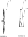
- F04D29/38—Blades
- F04D29/388—Blades characterised by construction
-
- F—MECHANICAL ENGINEERING; LIGHTING; HEATING; WEAPONS; BLASTING
- F28—HEAT EXCHANGE IN GENERAL
- F28D—HEAT-EXCHANGE APPARATUS, NOT PROVIDED FOR IN ANOTHER SUBCLASS, IN WHICH THE HEAT-EXCHANGE MEDIA DO NOT COME INTO DIRECT CONTACT
- F28D9/00—Heat-exchange apparatus having stationary plate-like or laminated conduit assemblies for both heat-exchange media, the media being in contact with different sides of a conduit wall
- F28D9/0093—Multi-circuit heat-exchangers, e.g. integrating different heat exchange sections in the same unit or heat-exchangers for more than two fluids
-
- F—MECHANICAL ENGINEERING; LIGHTING; HEATING; WEAPONS; BLASTING
- F05—INDEXING SCHEMES RELATING TO ENGINES OR PUMPS IN VARIOUS SUBCLASSES OF CLASSES F01-F04
- F05D—INDEXING SCHEME FOR ASPECTS RELATING TO NON-POSITIVE-DISPLACEMENT MACHINES OR ENGINES, GAS-TURBINES OR JET-PROPULSION PLANTS
- F05D2240/00—Components
- F05D2240/20—Rotors
- F05D2240/30—Characteristics of rotor blades, i.e. of any element transforming dynamic fluid energy to or from rotational energy and being attached to a rotor
- F05D2240/307—Characteristics of rotor blades, i.e. of any element transforming dynamic fluid energy to or from rotational energy and being attached to a rotor related to the tip of a rotor blade
-
- F—MECHANICAL ENGINEERING; LIGHTING; HEATING; WEAPONS; BLASTING
- F28—HEAT EXCHANGE IN GENERAL
- F28F—DETAILS OF HEAT-EXCHANGE AND HEAT-TRANSFER APPARATUS, OF GENERAL APPLICATION
- F28F2250/00—Arrangements for modifying the flow of the heat exchange media, e.g. flow guiding means; Particular flow patterns
- F28F2250/08—Fluid driving means, e.g. pumps, fans
Definitions
- the present disclosure relates to a compressed air generation system.
- a multi-stage compressor with one or more stages of intercooling is required.
- a multi-stage reciprocating compressor is incorporated for achieving high pressure ratios, which also generates high temperatures after compression.
- Water cooling of multi-stage reciprocating compressed air is to achieve desired cooling effect of the compressed air is well known, which require a separate plant for the cooling.
- Water cooling of compressed air require more space to build the heat-exchanger plant and complicated piping and valve arrangements to control the flow of water to the heat-exchanger plant. Hence more space required.
- the pressure ratio per stage is usually in the range 3-4 bar, and the adiabatically cooled air gets heated to high temperatures. Hence, an intercooler is placed immediately after the compression stage.
- An object of the present disclosure is to ameliorate one or more problems of the prior art or to at least provide a useful alternative.
- Yet another object of the present disclosure is to provide a compressed air generation system having multi-stage compression that is a standalone unit.
- Yet another object of the present disclosure is to provide a compressed air generation system having multi-stage compression that generates noise within the stipulated limits.
- Another object of the present disclosure is to provide a compressed air generation system having multi-stage compression that provides ease of installation by minimizing the requirement for cooling ducts.
- Embodiments are provided so as to thoroughly and fully convey the scope of the present disclosure as defined by the appended claims to the person skilled in the art. Numerous details are set forth. relating to specific components, and methods, to provide a complete understanding of embodiments of the present disclosure. It will be apparent to the person skilled in the art that the details provided in the embodiments should not be construed to limit the scope of the present disclosure, that is defined by the appended claims. In some embodiments, well-known processes, well-known apparatus structures, and well-known techniques are not described in detail.
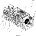
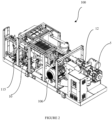
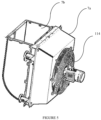
- a compressed air generation system 100 of the present disclosure will now be described in detail with reference to Figure 1 through Figure 8 .
- the compressed air generation system 100 comprises a multi-stage reciprocating compressor 1 and a combi-cooler assembly 7.
- the multi-stage compressor is a multi-stage reciprocating compressor 1, and includes a first reciprocating compression stage 102a, a second reciprocating compression stage 102b and a third reciprocating compression stage 102c.
- the first reciprocating compression stage 102a is configured to receive air at ambient pressure conditions.
- the first reciprocating compression stage 102a is configured to compress air to a first predetermined pressure value.
- the second reciprocating compression stage 102b is configured to be in fluid communication with the first reciprocating compression stage 102a.
- the second reciprocating compression stage 102b is configured to receive compressed air from the first reciprocating compression stage 102a,and is further configured to further compress air to a second predetermined pressure value.
- the third reciprocating compression stage 102c is configured to be in fluid communication with the second reciprocating compression stage 102b.
- the third reciprocating compression stage 102c is configured to receive compressed air from the second reciprocating compression stage 102b,and is further configured to further compress air to a third predetermined pressure value.
- Compression of air by the reciprocating compression stages 102a, 102b, 102c increases the temperature of the air.
- the resultant product of the compression thus is hot compressed air.
- the first predetermined pressure value ranges from 2.5 to 4 bar. In another embodiment, the second predetermined pressure value ranges from 12 to 16 bar. In yet another embodiment, the third predetermined pressure value ranges from 25 to 42 bar.
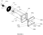
- the combi-cooler assembly 7 has at least two intercoolers 104a, 104b.
- the intercoolers 104a, 104b are configured to fluidly communicate with the reciprocating compression stages 102a, 102bto receive hot compressed air from the first reciprocating compression stage 102a and the second reciprocating compression stage 102b.
- the intercoolers 104a, 104b are configured to dissipate heat of the compressed air by passing the hot compressed air therethrough to generate relatively cooler compressed air.
- the compressed air generation system 100 is configured as a standalone plug-n-play unit.
- the multistage reciprocating compressor 1 and the combi-cooler assembly 7 are housed in a single enclosure.
- the compressed air generation system 100 is mounted on a primary mounting platform 2 having a secondary mounting platform 3 provided thereon, upon which the multi-stage reciprocating compressor 1 is configured to be mounted.
- a plurality of anti-vibrational mounts 4 is provided on the secondary mounting platform 3.
- the anti-vibrational mounts 4 are configured to allow mounting of the multi-stage reciprocating compressor 1 thereon, and are further configured to dissipate the vibrations exerted by the multi-stage reciprocating compressor 1.
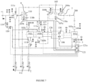
- An air distribution circuit 200 connecting the multistage reciprocating compressor 1 and the combi-cooler assembly 7, is configured to facilitate fluid communication between the multistage reciprocating compressor 1 and the combi-cooler assembly 7. More specifically, the air distribution circuit 200 allows the hot compressed air to flow from the first reciprocating compression stage 102a to the first inter-cooler (104a) of the combi-cooler assembly 7, then the cooled compressed air from the first inter-cooler (104a) of the combi-cooler assembly 7 to the second reciprocating compression stage 102b, hot compressed air from the second reciprocating compression stage 102b to the second inter-cooler (104b) of the combi-cooler assembly 7, and thereafter cooled compressed air from the second inter-cooler (104b) of the combi-cooler assembly 7 to the third reciprocating compression stage 102c.
- the air distribution circuit 200 is a closed loop circuit, and recirculates the air therewithin during unloading stage. In another embodiment, the air distribution circuit 200 is an open loop circuit which continuously takes in air and discharges compressed air.
- the multistage reciprocating compressor 1 includes a piston passing through each of the first reciprocating compression stage 102a, the second reciprocating compression stage 102b, and the third reciprocating compression stage 102c, the three pistons being mounted on a crankshaft that is driven by a prime mover.
- the pistons are configured to be linearly displaced in corresponding cylinders in a reciprocating manner to facilitate compression of air in the compression stages 102a, 102b, 102c.
- the multistage reciprocating compressor 1 includes a crank case 130 crankshaft that supports the pistons and the cylinders of the three compression stages 102a, 102b, 102c.
- the compressed air generation system 100 includes a radiator circuit 300.
- the radiator circuit 300 is configured to be in fluid communication with the first reciprocating compression stage 102a, the second reciprocating compression stage 102b, the third reciprocating compression stage 102c, and the crank case 130.
- the radiator circuit 300 is configured to carry a coolant fluid therein to facilitate dissipation of heat from the first reciprocating compression stage 102a, the second reciprocating compression stage 102b, the third reciprocating compression stage 102c and the crank case 130.
- crank case 130 contains oil which not only aids in lubrication of the crankshaft but also helps in cooling of the crankshaft with the help of the radiator circuit 300 passing through the case.
- the radiator circuit 300 is a closed loop circuit.
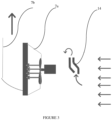
- each of the intercoolers 104a, 104b and radiator 105 includes a plurality of channels that are configured to allow the hot compressed air and coolant fluid therethrough.
- the channels carrying the coolant fluid and the hot compressed air are positioned alternately, to facilitate heat exchange therebetween. More specifically, the channels carrying the coolant fluid is disposed between channels carrying the hot compressed air inside the combi-cooler (7) assembly.
- Each of the intercoolers 104a, 104b includes an inlet of intercooler 108a provided thereon to allow hot compressed air to flow in, and an outlet of intercooler 108b configured thereon allow cool compressed air to flow out.
- the combi-cooler assembly 7 includes a radiator 105 configured to be fluid communication with the radiator circuit 300 to receive the hot coolant fluid from a casing channels of the first reciprocating compression stage 102a, the second reciprocating compression stage 102b, the third reciprocating compression stage 102c and the crank case 130.
- the radiator 105 is configured to facilitate heat dissipation of the coolant fluid of the radiator circuit 300.
- the radiator 105 includes a plurality of channels mounted along the walls thereof. The channels are configured to allow the coolant fluid to pass therethrough.
- an inlet of radiator 105a and an outlet of radiator 105b are provided on the radiator 105 to allow the coolant fluid to flow through the radiator 105.
- the radiator 105 includes a pump 10 for facilitating circulation of the coolant therethrough.
- the radiator 105 is fluidly connected to a surge tank 115 storing the coolant therein, and the pump 10 allows the flow of the coolant to the radiator 105.
- the coolant fluid inside the radiator 105 circuit may be water, glycol mixed with water or any other composition with water .
- the compressed air generation system 100 includes a compressor suction filter 5 provided at the inlet of each of the first compression stage 102a to provide filtered air thereto.
- the compressor suction filter 5 filters out all the unwanted particles from the air to prevent clogging of the various components of the compressed air generation system 100.
- a buffer vessels 103a, 103b, 103c are provided at the outlet of each of the first reciprocating compression stage 102a, the second reciprocating compression stage 102b and the third reciprocating compression stage 102c.
- the buffer vessels 103a, 103b, 103c are configured to provide buffer gas to compensate the flow from the first reciprocating compression stage 102a, the second reciprocating compression stage 102b and the third reciprocating compression stage 103c, thereby regulating the output flow of the compressed air.
- the combi-cooler assembly 7 is located at a lateral end of the enclosure.
- the compressed air generation system 100 includes an after-cooler assembly 8 provided downstream of the final stage of compression of the third reciprocating compression stage 102c.
- the after-cooler assembly 8 comprises an after-cooler heat exchanger 110 and an after-cooler fan 118b configured to reduce the temperature of the hot compressed air let out from the third reciprocating compression stage 102c.
- a condensate recovery units 111a, 111b, 111c are provided downstream of the first inter-cooler (104a), the second inter-cooler (104b) and after-cooler assembly 8.
- the condensate recovery units 111a,111b,111c are configured to remove condensate matter formed as a result of cooling the hot compressed air in the inter-cooler 7 and after-cooler assembly 8.
- the condensate recovery units 111a, 111b, 111c are also helps in minimizing the pulsations during the compression in each stage of the compressed air.
- a pressure regulator 119 is provided downstream of the condensate recovery unit 111c to regulate the pressure of the compressed air during unloading stage and reduce to ambient conditions before passing it back to the first reciprocating compression stage 102a, thereby completing the closed loop.
- a solenoid valve 120 is provided downstream of the pressure regulator 119 to allow or stop the flow of the air from the pressure regulator 119 to the first reciprocating compression stage 102a during unload conditions.
- the compressed air generation system 100 includes a first drive motor 106 connected to the crankcase.
- the first drive motor 106 is configured to drive the crankshaft.
- the compressed air generation system 100 includes a blower fan 118a provided in the combi-cooler assembly 7.
- the blower fan 118a is configured to dissipate heat from the hot compressed air and the hot coolant fluid passing through the intercoolers 104a, 104b and the radiator 105.
- a second drive motor 107a is provided to drive the blower fan 118a.
- the second drive motor 107a is arranged inside the combi-cooler assembly 7.
- the compressed air generation system 100 includes a third drive motor 107b connected to the after-cooler assembly 8.
- the third drive motor 107b is configured to drive the after-cooler fan 118b.
- the after-cooler fan configured to dissipate heat from the hot compressed air passing through after-cooler heat exchanger 110 from the third reciprocating compression stage 102c.
- Both the combi-cooler assembly 7 and after-cooler heat exchanger 110 are air cooled by blowing atmospheric air over the combi-cooler assembly 7 and after-cooler heat exchanger 110 with the help of the blower fan 118a and after-cooler fan 118b.
- the compressed air generation system 100 includes an electronic control panel 121, 121a configured to control the operation of the compressed air generation system 100, by controlling the power supplied to the various drive motors, controlling the solenoid valves at various locations to maintain the flow uniform throughout the circuit.
- air at ambient conditions is supplied to the first reciprocating compression stage 102a after passing the air through the compressor suction filter 5.
- the crankshaft displaces the piston to facilitate compression of air in the first reciprocating compression stage 102a.
- Hot compressed air at a first predetermined value is discharged from the first compression stage 102a.
- the buffer vessels 103a, 103b, 103c compensate the flow of the discharged compressed air from each reciprocating compression stage to the subsequent stage of compressor. Since, the temperature of the compressed air is very high, it is passed to the combi-cooler assembly 7, wherein the compressed air is lead through the first intercooler 104a to help dissipation of the heat from the hot compressed air.
- the cooled compressed air is then passed to the condensate recovery unit 111a, helps in removing the condensate matter from the air before it enter into the second reciprocating compression stage 102b, where it is again compressed to a second predetermined value.
- the compressed air from the second reciprocating compression stage 102b is passed then to the combi-cooler assembly 7, wherein it is passed through the second intercooler 104b to help in dissipation of heat.
- the cooled compressed air is thereafter passed to the condensate recovery unit 111b, helps in removing the condensate matter from the air before it enter into the third reciprocating compression stage 102c , wherein it is further compressed to a third predetermined value.
- the resultant compressed air is then passed through the after-cooler assembly 8 where it is cooled to a desired temperature value. Thereafter, the cooled compressed air is passed through a condensate recovery unit 111c to allow removal of condensate matter from the air, and then discharged for a particular application. If there is no requirement of compressed air discharge, i.e., at a noload condition, the pressure of the compressed air is reduced to ambient conditions and again passed to the first reciprocating compression stage 102a through the pressure regulator 119 and the solenoid valve 120.
- the coolant fluid flows from through the radiator circuit 300 to cool the components of the compressed air generation system 100 namely, the crank case 130, the first reciprocating compression stage 102a, the second reciprocating compression stage 102b, and the third reciprocating compression stage 102c of the multi-stage reciprocating compressor 1.
- the coolant fluid flows into the crank case 130 where it exchanges heat with the oil contained in the crank case 130, thereby cooling the oil.
- the coolant fluid passes through the multi-stage reciprocating compressor 1 to dissipate heat therefrom.
- the coolant fluid is thereafter made to pass through the radiator circuit 300, and passed into the inlet of radiator 105a.
- the heat of the coolant fluid while flowing through the radiator 105 is dissipated by the air blown by the blower fan 118a over the radiator 105.
- the coolant fluid condenses.
- the condensed coolant fluid flows out through the radiator exit and passed to the surge tank 115, from where it is passed back to the crank case 130, the first reciprocating compression stage 102a, the second reciprocating compression stage 102b, and the third reciprocating compression stage 102c of the multi-stage reciprocating compressor 1.
- vents 126 are provided at predetermined locations on the pistons.
- the vents 126 allow passage of any air content that may be leaked from the compressor during compression.
Landscapes
- Engineering & Computer Science (AREA)
- Mechanical Engineering (AREA)
- General Engineering & Computer Science (AREA)
- Physics & Mathematics (AREA)
- Thermal Sciences (AREA)
- Compressor (AREA)
- Compressors, Vaccum Pumps And Other Relevant Systems (AREA)
Claims (13)
- Drucklufterzeugungssystem (100), umfassend:einen mehrstufigen Kolbenkompressor (1), einschließend:eine erste Kolbenkompressionsstufe (102a), die konfiguriert ist, um bei Umgebungsdruckbedingungen Luft zu empfangen, wobei die erste Kolbenkompressionsstufe (102a) konfiguriert ist, um Luft auf einen ersten vorbestimmten Druckwert zu komprimieren;eine zweite Kolbenkompressionsstufe (102b), die in Fluidverbindung mit der ersten Kolbenkompressionsstufe (102a) steht, wobei die zweite Kolbenkompressionsstufe (102b) konfiguriert ist, um Druckluft von der ersten Kolbenkompressionsstufe (102a) zu empfangen, und wobei die zweite Kolbenkompressionsstufe (102b) konfiguriert ist, um von der ersten Kolbenkompressionsstufe (102a) empfangene Druckluft auf einen zweiten vorbestimmten Druckwert zu komprimieren; undeine dritte Kolbenkompressionsstufe (102c), die in Fluidverbindung mit der zweiten Kolbenkompressionsstufe (102b) steht, wobei die dritte Kolbenkompressionsstufe (102c) konfiguriert ist, um Druckluft von der zweiten Kolbenkompressionsstufe (102b) zu empfangen, und wobei die dritte Kolbenkompressionsstufe (102c) konfiguriert ist, um von der zweiten Kolbenkompressionsstufe (102b) empfangene Druckluft auf einen dritten vorbestimmten Druckwert zu komprimieren;eine Kombikühleranordnung (7), die mindestens zwei Zwischenkühler (104a, 104b) umfasst, wobei die Zwischenkühler (104a, 104b) in Fluidverbindung mit der ersten und der zweiten Kolbenkompressionsstufe (102a, 102b) stehen, um heiße Druckluft von der ersten Kolbenkompressionsstufe (102a) und der zweiten Kolbenkompressionsstufe (102b) zu empfangen, wobei die Zwischenkühler (104a, 104b) konfiguriert sind, um Wärme der Druckluft abzuleiten, indem die heiße Druckluft dort hindurch geleitet wird, um relativ kühlere Druckluft für eine nächste nachfolgende Stufe zu erzeugen;eine Nachkühleranordnung (8), die konfiguriert ist, um mit der dritten Kolbenkompressionsstufe (102c) in Verbindung zu stehen, wobei die Nachkühleranordnung (8) konfiguriert ist, um die Temperatur der heißen Druckluft, die aus der dritten Kolbenkompressionsstufe (102c) herauskommt, zu verringern;dadurch gekennzeichnet, dass das Drucklufterzeugungssystem (100) weiter einschließt:einen Radiatorkreislauf (300), der in Fluidverbindung mit der ersten Kolbenkompressionsstufe (102a), der zweiten Kolbenkompressionsstufe (102b), der dritten Kolbenkompressionsstufe (102c) und einem Kurbelgehäuse (130), das einen Teil des mehrstufigen Kolbenkompressors (1) bildet, steht; unddass der Radiatorkreislauf (300) konfiguriert ist, um darin ein Kühlmittelfluid zu befördern, um die Wärmeableitung von der ersten Kolbenkompressionsstufe (102a), der zweiten Kolbenkompressionsstufe (102b), der dritten Kolbenkompressionsstufe (102c) und dem Kurbelgehäuse (130) zu erleichtern; unddass die Kombikühleranordnung (7) einen Radiator (105) einschließt, der in Fluidverbindung mit dem Radiatorkreislauf (300) steht oder einen Teil davon bildet, um das heiße Kühlmittelfluid zu empfangen, wobei der Radiator (105) konfiguriert ist, um die Wärmeableitung von dem Kühlmittelfluid des Radiatorkreislaufs (300) zu erleichtern; unddass das Drucklufterzeugungssystem weiter ein Gebläse (118a) einschließt, das innerhalb der Kombikühleranordnung (7) angeordnet ist, wobei das Gebläse (118a) konfiguriert ist, um Wärme von der Druckluft, die durch die Zwischenkühler (104a, 104b) und den Radiator (105) hindurch geleitet wird, abzuleiten.
- Drucklufterzeugungssystem (100) nach Anspruch 1, dadurch gekennzeichnet, dass der mehrstufige Kolbenkompressor (1), die Kombikühleranordnung (7) und die Nachkühleranordnung (8) in einem einzigen Gehäuse untergebracht sind.
- Drucklufterzeugungssystem (100) nach Anspruch 1 oder 2, dadurch gekennzeichnet, dass das Drucklufterzeugungssystem (100) einen Luftverteilungskreislauf (200) einschließt, der konfiguriert ist, um die Fluidverbindung zwischen dem mehrstufigen Kolbenkompressor (1) und der Kombikühleranordnung (7) zu erleichtern.
- Drucklufterzeugungssystem (100) nach Anspruch 3, dadurch gekennzeichnet, dass der Luftverteilungskreislauf (200) ein geschlossener Kreislauf ist.
- Drucklufterzeugungssystem (100) nach Anspruch 1, dadurch gekennzeichnet, dass der Radiatorkreislauf (300) ein geschlossener Kreislauf ist.
- Drucklufterzeugungssystem (100) nach Anspruch 1 oder 5, dadurch gekennzeichnet, dass jeder der Zwischenkühler (104a, 104b) und ein Radiator (105), der in Fluidverbindung mit dem Radiatorkreislauf steht oder einen Teil davon bildet, eine Vielzahl von Kanälen einschließen, die konfiguriert sind, um der heißen Druckluft und dem Kühlmittelfluid zu ermöglichen, abwechselnd dort hindurch geleitet zu werden, um den Wärmeaustausch dazwischen zu erleichtern.
- Drucklufterzeugungssystem (100) nach Anspruch 1 oder 6, dadurch gekennzeichnet, dass der Radiator (105) eine Vielzahl von Kanälen einschließt, die entlang der Wände davon montiert sind, wobei die Kanäle konfiguriert sind, um dem Kühlmittelfluid zu ermöglichen, dort hindurch geleitet zu werden.
- Drucklufterzeugungssystem (100) nach Anspruch 1 oder 6, dadurch gekennzeichnet, dass der Radiator (105) eine Pumpe (10) einschließt, die die Zirkulation des Kühlmittelfluids dort hindurch erleichtert.
- Drucklufterzeugungssystem (100) nach Anspruch 1, dadurch gekennzeichnet, dass das Kühlmittelfluid eins oder mehreres umfasst, ausgewählt aus der Gruppe, umfassend: Wasser, mit Glykol gemischt mit Waser und eine beliebige andere Zusammensetzung mit Wasser.
- Drucklufterzeugungssystem (100) nach einem der vorstehenden Ansprüche, dadurch gekennzeichnet, dass das Drucklufterzeugungssystem weiter einen Pufferbehälter (103a, 103b, 103c) umfasst, der am Auslass jeder der ersten Kolbenkompressionsstufe (102a) und der zweiten Kolbenkompressionsstufe (102b) und der dritten Kolbenkompressionsstufe (102c) bereitgestellt ist, wobei die Pufferbehälter (103a, 103b, 103c) konfiguriert sind, einen Strömungsausgleich von der ersten Kolbenkompressionsstufe (102a) und der zweiten Kolbenkompressionsstufe (102b) und der dritten Kolbenkompressionsstufe (102c) bereitzustellen.
- Drucklufterzeugungssystem (100) nach Anspruch 2, dadurch gekennzeichnet, dass sich die Kombikühleranordnung (7) an einem seitlichen Ende des Gehäuses befindet.
- Drucklufterzeugungssystem (100) nach einem der vorstehenden Ansprüche, dadurch gekennzeichnet, dass Kondensatrückgewinnungseinheiten (111a, 111b, 111c) stromabwärts der Zwischenkühler (104a, 104b) und der Nachkühleranordnung (8) bereitgestellt sind, wobei die Kondensatrückgewinnungseinheiten (111a, 111b, 111c) konfiguriert sind, um Kondensatstoffe zu entfernen, die infolge des Kühlens der heißen Druckluft in den Zwischenkühlern (104a, 104b) und der Nachkühleranordnung (8) gebildet werden.
- Drucklufterzeugungssystem (100) nach einem der vorstehenden Ansprüche, dadurch gekennzeichnet, dass das Drucklufterzeugungssystem weiter einen Ausgleichsbehälter (115) einschließt, der konfiguriert ist, um das Kühlmittelfluid darin zu speichern.
Applications Claiming Priority (1)
| Application Number | Priority Date | Filing Date | Title |
|---|---|---|---|
| IN202121018988 | 2021-04-24 |
Publications (3)
| Publication Number | Publication Date |
|---|---|
| EP4080048A1 EP4080048A1 (de) | 2022-10-26 |
| EP4080048B1 true EP4080048B1 (de) | 2025-04-09 |
| EP4080048C0 EP4080048C0 (de) | 2025-04-09 |
Family
ID=81346323
Family Applications (1)
| Application Number | Title | Priority Date | Filing Date |
|---|---|---|---|
| EP22169497.9A Active EP4080048B1 (de) | 2021-04-24 | 2022-04-22 | Drucklufterzeugungssystem |
Country Status (3)
| Country | Link |
|---|---|
| US (1) | US12123407B2 (de) |
| EP (1) | EP4080048B1 (de) |
| CN (1) | CN114738236B (de) |
Families Citing this family (1)
| Publication number | Priority date | Publication date | Assignee | Title |
|---|---|---|---|---|
| US20240318786A1 (en) * | 2023-03-23 | 2024-09-26 | Clean Recompression, LLC | Method and System For Compact and Hyper Mobile Recompression |
Family Cites Families (43)
| Publication number | Priority date | Publication date | Assignee | Title |
|---|---|---|---|---|
| US1473314A (en) * | 1923-06-16 | 1923-11-06 | Poccia Loreto | Air compressor |
| US2738659A (en) * | 1952-11-03 | 1956-03-20 | Karl G Heed | Air compressor and cooler |
| US3096927A (en) * | 1959-10-13 | 1963-07-09 | Wahl Hermann | Relieving device for multiple stage compressors |
| US3216648A (en) * | 1962-04-02 | 1965-11-09 | Stephen H Ford | Automatic blowdown system for compressors |
| US3462074A (en) * | 1968-02-23 | 1969-08-19 | John E Grimmer | Air compressor apparatus and method |
| US4022550A (en) * | 1976-03-19 | 1977-05-10 | Gardner-Denver Company | Enclosed compressor unit |
| US4097202A (en) * | 1976-06-21 | 1978-06-27 | Billy Frank Price | Auxiliary compressor assembly |
| JPS61145887U (de) * | 1985-03-04 | 1986-09-09 | ||
| US5203680A (en) * | 1989-10-27 | 1993-04-20 | Gas Jack, Inc. | Integral gas compressor and internal combustion engine |
| US5106270A (en) * | 1991-01-10 | 1992-04-21 | Westinghouse Air Brake Company | Air-cooled air compressor |
| US5386873A (en) * | 1993-06-09 | 1995-02-07 | Ingersoll-Rand Company | Cooling system for engine-driven multi-stage centrifugal compressor |
| JP3474704B2 (ja) * | 1996-03-29 | 2003-12-08 | アネスト岩田株式会社 | 二段空冷往復圧縮機の冷却構造 |
| US5947711A (en) * | 1997-04-16 | 1999-09-07 | Gardner Denver Machinery, Inc. | Rotary screw air compressor having a separator and a cooler fan assembly |
| US6203285B1 (en) * | 1998-05-18 | 2001-03-20 | Westinghouse Air Brake Company | Compressor intercooler unloader arrangement |
| JP4003378B2 (ja) * | 2000-06-30 | 2007-11-07 | 株式会社日立プラントテクノロジー | スクリュー圧縮機 |
| US6447264B1 (en) * | 2001-02-05 | 2002-09-10 | Ingersoll-Rand Company | Compressor system |
| US6692235B2 (en) * | 2001-07-30 | 2004-02-17 | Cooper Cameron Corporation | Air cooled packaged multi-stage centrifugal compressor system |
| US6629825B2 (en) * | 2001-11-05 | 2003-10-07 | Ingersoll-Rand Company | Integrated air compressor |
| US6695591B2 (en) | 2002-05-20 | 2004-02-24 | Grimmer Industries, Inc. | Multi-stage gas compressor system |
| CN1916410B (zh) * | 2005-08-19 | 2010-10-06 | 科拉克集团公开公司 | 多级无油式气体压缩机 |
| US20070044938A1 (en) * | 2005-08-26 | 2007-03-01 | Farley Mary L | Dual surge tank for vehicle cooling system |
| CA2759121C (en) * | 2008-04-16 | 2021-07-27 | Mitja Victor Hinderks | New reciprocating machines and other devices |
| US20090297368A1 (en) * | 2008-06-03 | 2009-12-03 | Wabtec Holding Corp. | Single Piece Water Over Air Intercooler for a Reciprocating Air Compressor |
| JP5248373B2 (ja) * | 2009-03-11 | 2013-07-31 | 株式会社日立産機システム | 水噴射式空気圧縮機 |
| JP2010275939A (ja) * | 2009-05-29 | 2010-12-09 | Hitachi Industrial Equipment Systems Co Ltd | 水冷式オイルフリー空気圧縮機 |
| DE102010008063A1 (de) * | 2010-02-16 | 2011-08-18 | WABCO GmbH, 30453 | Druckluftkompressor und Verfahren zum Betrieb eines Druckluftkompressors |
| EP2564130B1 (de) * | 2010-04-29 | 2018-07-11 | Carrier Corporation | Kältedampfkompressionssystem mit zwischenkühler |
| KR101237972B1 (ko) * | 2010-10-25 | 2013-02-28 | 삼성테크윈 주식회사 | 압축 장치 |
| US8826893B2 (en) * | 2011-01-14 | 2014-09-09 | General Electric Company | Thermal management systems and methods |
| US9897082B2 (en) * | 2011-09-15 | 2018-02-20 | General Electric Company | Air compressor prognostic system |
| GB2500871B (en) * | 2012-04-05 | 2017-03-01 | Ford Global Tech Llc | An Air to Liquid Heat Exchanger |
| US8534039B1 (en) * | 2012-04-16 | 2013-09-17 | TAS Energy, Inc. | High performance air-cooled combined cycle power plant with dual working fluid bottoming cycle and integrated capacity control |
| DE202013104306U1 (de) * | 2013-09-20 | 2013-10-31 | Gardner Denver Deutschland Gmbh | Trockenlaufender Kompressor zur Erzeugung von Druckluft |
| EP3069024A4 (de) * | 2013-10-18 | 2017-08-23 | Steven L. Wilhelm | Kompressoren |
| US20150285264A1 (en) * | 2014-04-07 | 2015-10-08 | Union Pacific Railroad Company | Air compressor with self contained cooling system |
| US9951763B2 (en) * | 2014-05-09 | 2018-04-24 | Westinghouse Air Brake Technologies Corporation | Compressor cooled by a temperature controlled fan |
| WO2017161118A1 (en) * | 2016-03-17 | 2017-09-21 | Powerphase Llc | Gas turbine modular air cooling system |
| EP3456966B1 (de) * | 2016-05-09 | 2020-11-18 | Hitachi Industrial Equipment Systems Co., Ltd. | Paketverdichter |
| US10153524B2 (en) * | 2016-06-30 | 2018-12-11 | Faraday&Future Inc. | Vehicle cooling system using gravity based fluid flow |
| BE1024396B1 (nl) | 2016-10-25 | 2018-02-13 | Atlas Copco Airpower Naamloze Vennootschap | Compressorinstallatie met drooginrichting voor samengeperst gas en werkwijze voor het drogen van samengeperst gas. |
| US10900499B2 (en) * | 2017-02-06 | 2021-01-26 | Ford Global Technologies, Llc | Cooling fans for engine cooling system |
| DE102017107602B3 (de) * | 2017-04-10 | 2018-09-20 | Gardner Denver Deutschland Gmbh | Kompressoranlage mit interner Luft-Wasser-Kühlung |
| US11913445B2 (en) * | 2018-03-20 | 2024-02-27 | Enersize Oy | Method for designing, gauging and optimizing a multiple compressor system with respect to energy efficiency |
-
2022
- 2022-03-31 CN CN202210344674.8A patent/CN114738236B/zh active Active
- 2022-04-05 US US17/713,272 patent/US12123407B2/en active Active
- 2022-04-22 EP EP22169497.9A patent/EP4080048B1/de active Active
Also Published As
| Publication number | Publication date |
|---|---|
| CN114738236B (zh) | 2024-04-26 |
| US20220341412A1 (en) | 2022-10-27 |
| CN114738236A (zh) | 2022-07-12 |
| EP4080048A1 (de) | 2022-10-26 |
| US12123407B2 (en) | 2024-10-22 |
| EP4080048C0 (de) | 2025-04-09 |
Similar Documents
| Publication | Publication Date | Title |
|---|---|---|
| US7717069B2 (en) | Engine cooling system having two cooling circuits | |
| US6551082B2 (en) | Oil free type screw compressor | |
| BE1013692A3 (nl) | Hogedruk, meertraps-centrifugaalcompressor. | |
| US10359044B2 (en) | Compressor system | |
| US6692235B2 (en) | Air cooled packaged multi-stage centrifugal compressor system | |
| US6374612B1 (en) | Interstage cooling of a multi-compressor turbocharger | |
| CN101542215A (zh) | 压缩机 | |
| EP3064866A1 (de) | Modulierte überdimensionierte verdichterkonfiguration für einen flash-gas-bypass in einem kohlendioxidkühlsystem | |
| EP4080048B1 (de) | Drucklufterzeugungssystem | |
| US6609484B2 (en) | Engine cooling system | |
| EP3904815B1 (de) | Verfahren für ein verbessertes kühlsystem mit geschlossenem kreislauf | |
| EP1284402A2 (de) | Vorrichtung und Verfahren zur Kühlung | |
| US4279574A (en) | Energy recovery system | |
| EP0397760B1 (de) | Verfahren und Vorrichtung zur Rückgewinnung von Kältemittel | |
| US10760490B2 (en) | Gas turbine efficiency and power augmentation system's modular air cooling system and methods of using the same | |
| JP2011153760A (ja) | 2段圧縮装置 | |
| CN220343282U (zh) | 一种压缩空气制冷增氧设备 | |
| CN215333650U (zh) | 一种用于离心压缩机的多功能冷却系统 | |
| US11846457B2 (en) | Transportation refrigeration modular unit | |
| JPH07217579A (ja) | スクリュー圧縮機の冷却システム | |
| JPH01310189A (ja) | オイルフリースクリュ圧縮機の冷却装置 | |
| CN119452214A (zh) | 用于hvac&r系统的压缩机系统 | |
| CN119497809A (zh) | 用于供暖、通风、空气调节和/或制冷系统的压缩机系统 | |
| HK1238315A1 (en) | Piston compressor | |
| HK1238315B (zh) | 活塞式压缩机 |
Legal Events
| Date | Code | Title | Description |
|---|---|---|---|
| PUAI | Public reference made under article 153(3) epc to a published international application that has entered the european phase |
Free format text: ORIGINAL CODE: 0009012 |
|
| STAA | Information on the status of an ep patent application or granted ep patent |
Free format text: STATUS: THE APPLICATION HAS BEEN PUBLISHED |
|
| AK | Designated contracting states |
Kind code of ref document: A1 Designated state(s): AL AT BE BG CH CY CZ DE DK EE ES FI FR GB GR HR HU IE IS IT LI LT LU LV MC MK MT NL NO PL PT RO RS SE SI SK SM TR |
|
| STAA | Information on the status of an ep patent application or granted ep patent |
Free format text: STATUS: REQUEST FOR EXAMINATION WAS MADE |
|
| 17P | Request for examination filed |
Effective date: 20230425 |
|
| RBV | Designated contracting states (corrected) |
Designated state(s): AL AT BE BG CH CY CZ DE DK EE ES FI FR GB GR HR HU IE IS IT LI LT LU LV MC MK MT NL NO PL PT RO RS SE SI SK SM TR |
|
| GRAP | Despatch of communication of intention to grant a patent |
Free format text: ORIGINAL CODE: EPIDOSNIGR1 |
|
| STAA | Information on the status of an ep patent application or granted ep patent |
Free format text: STATUS: GRANT OF PATENT IS INTENDED |
|
| INTG | Intention to grant announced |
Effective date: 20241030 |
|
| GRAS | Grant fee paid |
Free format text: ORIGINAL CODE: EPIDOSNIGR3 |
|
| RAP3 | Party data changed (applicant data changed or rights of an application transferred) |
Owner name: ATLAS COPCO (INDIA) PRIVATE LIMITED |
|
| GRAA | (expected) grant |
Free format text: ORIGINAL CODE: 0009210 |
|
| STAA | Information on the status of an ep patent application or granted ep patent |
Free format text: STATUS: THE PATENT HAS BEEN GRANTED |
|
| RAP1 | Party data changed (applicant data changed or rights of an application transferred) |
Owner name: ATLAS COPCO AIRPOWER, NAAMLOZE VENNOOTSCHAP |
|
| AK | Designated contracting states |
Kind code of ref document: B1 Designated state(s): AL AT BE BG CH CY CZ DE DK EE ES FI FR GB GR HR HU IE IS IT LI LT LU LV MC MK MT NL NO PL PT RO RS SE SI SK SM TR |
|
| REG | Reference to a national code |
Ref country code: GB Ref legal event code: FG4D |
|
| REG | Reference to a national code |
Ref country code: CH Ref legal event code: EP |
|
| REG | Reference to a national code |
Ref country code: DE Ref legal event code: R096 Ref document number: 602022012775 Country of ref document: DE |
|
| REG | Reference to a national code |
Ref country code: IE Ref legal event code: FG4D |
|
| U01 | Request for unitary effect filed |
Effective date: 20250505 |
|
| U07 | Unitary effect registered |
Designated state(s): AT BE BG DE DK EE FI FR IT LT LU LV MT NL PT RO SE SI Effective date: 20250522 |
|
| U20 | Renewal fee for the european patent with unitary effect paid |
Year of fee payment: 4 Effective date: 20250527 |
|
| PG25 | Lapsed in a contracting state [announced via postgrant information from national office to epo] |
Ref country code: ES Free format text: LAPSE BECAUSE OF FAILURE TO SUBMIT A TRANSLATION OF THE DESCRIPTION OR TO PAY THE FEE WITHIN THE PRESCRIBED TIME-LIMIT Effective date: 20250409 |
|
| PG25 | Lapsed in a contracting state [announced via postgrant information from national office to epo] |
Ref country code: NO Free format text: LAPSE BECAUSE OF FAILURE TO SUBMIT A TRANSLATION OF THE DESCRIPTION OR TO PAY THE FEE WITHIN THE PRESCRIBED TIME-LIMIT Effective date: 20250709 Ref country code: GR Free format text: LAPSE BECAUSE OF FAILURE TO SUBMIT A TRANSLATION OF THE DESCRIPTION OR TO PAY THE FEE WITHIN THE PRESCRIBED TIME-LIMIT Effective date: 20250710 |
|
| PG25 | Lapsed in a contracting state [announced via postgrant information from national office to epo] |
Ref country code: PL Free format text: LAPSE BECAUSE OF FAILURE TO SUBMIT A TRANSLATION OF THE DESCRIPTION OR TO PAY THE FEE WITHIN THE PRESCRIBED TIME-LIMIT Effective date: 20250409 |
|
| PG25 | Lapsed in a contracting state [announced via postgrant information from national office to epo] |
Ref country code: HR Free format text: LAPSE BECAUSE OF FAILURE TO SUBMIT A TRANSLATION OF THE DESCRIPTION OR TO PAY THE FEE WITHIN THE PRESCRIBED TIME-LIMIT Effective date: 20250409 |
|
| PG25 | Lapsed in a contracting state [announced via postgrant information from national office to epo] |
Ref country code: RS Free format text: LAPSE BECAUSE OF FAILURE TO SUBMIT A TRANSLATION OF THE DESCRIPTION OR TO PAY THE FEE WITHIN THE PRESCRIBED TIME-LIMIT Effective date: 20250709 |
|
| PG25 | Lapsed in a contracting state [announced via postgrant information from national office to epo] |
Ref country code: IS Free format text: LAPSE BECAUSE OF FAILURE TO SUBMIT A TRANSLATION OF THE DESCRIPTION OR TO PAY THE FEE WITHIN THE PRESCRIBED TIME-LIMIT Effective date: 20250809 |
|
| REG | Reference to a national code |
Ref country code: CH Ref legal event code: H13 Free format text: ST27 STATUS EVENT CODE: U-0-0-H10-H13 (AS PROVIDED BY THE NATIONAL OFFICE) Effective date: 20251125 |
|
| PG25 | Lapsed in a contracting state [announced via postgrant information from national office to epo] |
Ref country code: SM Free format text: LAPSE BECAUSE OF FAILURE TO SUBMIT A TRANSLATION OF THE DESCRIPTION OR TO PAY THE FEE WITHIN THE PRESCRIBED TIME-LIMIT Effective date: 20250409 |
|
| PG25 | Lapsed in a contracting state [announced via postgrant information from national office to epo] |
Ref country code: CH Free format text: LAPSE BECAUSE OF NON-PAYMENT OF DUE FEES Effective date: 20250430 |
|
| PG25 | Lapsed in a contracting state [announced via postgrant information from national office to epo] |
Ref country code: CZ Free format text: LAPSE BECAUSE OF FAILURE TO SUBMIT A TRANSLATION OF THE DESCRIPTION OR TO PAY THE FEE WITHIN THE PRESCRIBED TIME-LIMIT Effective date: 20250409 |
|
| PG25 | Lapsed in a contracting state [announced via postgrant information from national office to epo] |
Ref country code: SK Free format text: LAPSE BECAUSE OF FAILURE TO SUBMIT A TRANSLATION OF THE DESCRIPTION OR TO PAY THE FEE WITHIN THE PRESCRIBED TIME-LIMIT Effective date: 20250409 |
|
| PG25 | Lapsed in a contracting state [announced via postgrant information from national office to epo] |
Ref country code: MC Free format text: LAPSE BECAUSE OF FAILURE TO SUBMIT A TRANSLATION OF THE DESCRIPTION OR TO PAY THE FEE WITHIN THE PRESCRIBED TIME-LIMIT Effective date: 20250409 |
|
| PLBE | No opposition filed within time limit |
Free format text: ORIGINAL CODE: 0009261 |
|
| STAA | Information on the status of an ep patent application or granted ep patent |
Free format text: STATUS: NO OPPOSITION FILED WITHIN TIME LIMIT |