EP4080001B1 - Panic bar device - Google Patents
Panic bar device Download PDFInfo
- Publication number
- EP4080001B1 EP4080001B1 EP20842591.8A EP20842591A EP4080001B1 EP 4080001 B1 EP4080001 B1 EP 4080001B1 EP 20842591 A EP20842591 A EP 20842591A EP 4080001 B1 EP4080001 B1 EP 4080001B1
- Authority
- EP
- European Patent Office
- Prior art keywords
- bar device
- panic bar
- rotating shaft
- arm
- bearing assembly
- Prior art date
- Legal status (The legal status is an assumption and is not a legal conclusion. Google has not performed a legal analysis and makes no representation as to the accuracy of the status listed.)
- Active
Links
Images


Classifications
-
- E—FIXED CONSTRUCTIONS
- E05—LOCKS; KEYS; WINDOW OR DOOR FITTINGS; SAFES
- E05B—LOCKS; ACCESSORIES THEREFOR; HANDCUFFS
- E05B65/00—Locks or fastenings for special use
- E05B65/10—Locks or fastenings for special use for panic or emergency doors
- E05B65/1046—Panic bars
- E05B65/106—Panic bars pivoting
- E05B65/1066—Panic bars pivoting the pivot axis being substantially parallel to the longitudinal axis of the bar
-
- E—FIXED CONSTRUCTIONS
- E05—LOCKS; KEYS; WINDOW OR DOOR FITTINGS; SAFES
- E05B—LOCKS; ACCESSORIES THEREFOR; HANDCUFFS
- E05B3/00—Fastening knobs or handles to lock or latch parts
- E05B3/04—Fastening the knob or the handle shank to the spindle by screws, springs or snap bolts
-
- E—FIXED CONSTRUCTIONS
- E05—LOCKS; KEYS; WINDOW OR DOOR FITTINGS; SAFES
- E05B—LOCKS; ACCESSORIES THEREFOR; HANDCUFFS
- E05B63/00—Locks or fastenings with special structural characteristics
- E05B63/0056—Locks with adjustable or exchangeable lock parts
-
- E—FIXED CONSTRUCTIONS
- E05—LOCKS; KEYS; WINDOW OR DOOR FITTINGS; SAFES
- E05B—LOCKS; ACCESSORIES THEREFOR; HANDCUFFS
- E05B63/00—Locks or fastenings with special structural characteristics
- E05B63/04—Locks or fastenings with special structural characteristics for alternative use on the right-hand or left-hand side of wings
- E05B63/042—Locks or fastenings with special structural characteristics for alternative use on the right-hand or left-hand side of wings constructed symmetrically
-
- E—FIXED CONSTRUCTIONS
- E05—LOCKS; KEYS; WINDOW OR DOOR FITTINGS; SAFES
- E05C—BOLTS OR FASTENING DEVICES FOR WINGS, SPECIALLY FOR DOORS OR WINDOWS
- E05C21/00—Arrangements or combinations of wing fastening, securing, or holding devices, not covered by a single preceding main group; Locking kits
Definitions
- the present invention relates to a panic bar device for a door.
- EP2820209B1 discloses a mechanism with an operating handle in the form of a bar for a door, window, or the like, with a leaf mounted on a fixed frame.
- the mechanism comprises a bearing device on which the bar is supported, a lock with a lock mechanism, and a connecting device for connecting the lock.
- the bearing device comprises a bearing plate configured for fixing the bearing device to the door.
- the bearing device further comprises a bearing body with a U-shaped section.
- the bearing body has two U-shaped arms protruding from the bearing plate.
- Each U-shaped arm comprises a bearing receptor, the bearing receptors of both arms being aligned with one another.
- the bearing shaft of the bar is arranged in each of the bearing receptors.
- the connecting device comprises a driving lever attached to the bearing shaft of the bar in a rotation-resistant manner, and upon rotation it pushes a projection of an element which rotates about a shaft acting on the lock.
- DE102009045440A1 describes a panic bar device for an escape door with a door lock and a bar handle which is mounted on the inside of a door leaf via at least one pivoted lever arm.
- the lever arm is connected via a lock mechanism to the door lock, which can be opened by pressing the bar handle.
- the lock mechanism has a projecting element, and the lever arm has a mounting slot such that when the projecting element is inserted into the mounting slot, both get positively interlocked.
- a locking screw is provided to secure the connection between the projecting element and the mounting slot.
- EP491486A1 describes a panic bar device which comprises a housing comprising a back plate for mounting on a door and providing guide means for the rack of a rack-and-pinion mechanism, the rack being free to move, to a limited extent, in a plane parallel to the plane of the back plate.
- the pinion is adapted to receive the spindle of an anti-panic mortise lock.
- the panic bar device further comprises a lever handle pivotally mounted on the housing and comprising a projection which cooperates with another projection attached to the rack, such that operation of the lever handle drives the rack within the guide means.
- the panic bar device comprises biassing means tending to urge the rack in the direction opposed to that in which it is driven by the lever handle.
- the panic bar device can be adjusted by means of an adjustment screw located in a threaded aperture in the lever handle, such that when the screw is screwed so that its point projects beyond the handle, the angle between the handle and the door is reduced.
- EP3406829A1 describes a panic bar device having an actuating rod pivotably mounted about an actuating shaft by means of pivoting levers.
- the pivot levers are adjustable in length.
- the pivot levers are designed to be telescopic.
- the pivot levers have first and second sections which are guided displaceably relative to one another in the longitudinal direction of the pivot lever.
- EP3018272B1 describes a panic bar device with a shaft for transmitting a torque and a bearing block for supporting the shaft, the shaft being mounted in a single bearing point of the bearing block.
- the panic bar device has a base plate associated to the bearing block such that a square receptacle is held in a rotationally movable manner between the base plate and the bearing block.
- the bearing block has adjustable stop means for limiting the rotational movement of the square receptacle.
- the object of the invention is to provide a panic bar device, as defined in the claims.
- the panic bar device of the invention comprises a first bearing assembly and a second bearing assembly configured for being fixed to a door, a first arm pivotally coupled at a first end to the first bearing assembly by means of a first operating shaft, a second arm pivotally coupled at a first end to the second bearing assembly by means of a second operating shaft, and a bar coupled to a second end of the first arm and to a second end of the second arm, such that the bar, the first arm, and the second arm pivot with respect to the bearing assemblies when the bar is pushed.
- the bearing assembly comprises a rotating shaft comprising a housing for the operating shaft, the rotating shaft being configured for rotating together with the operating shaft and the respective arm of the panic bar device.
- the panic bar device further comprises a plurality of pairs of arms configured for having different inclinations in the panic bar device with respect to a front surface of the door in a standby state of the panic bar device in which the bar is not pushed, the different inclinations being obtained by varying the angular orientation of the operating shaft with respect to the arms, the first arm and the second arm being selected from the plurality of pairs of arms.
- the same panic bar device can be used with different pairs of arms makes it possible that the same panic bar device can be used with different locks existing on the market, such that depending on the characteristics of the lock to be used with the panic bar device and the force that needs to be exerted on the pair of arms to open the lock, the pair of arms can be selected such that they have the suitable length and inclination with respect to the front surface of the door.
- FIGS 1 to 15 show an embodiment of the panic bar device 100 of the invention.
- the panic bar device 100 of the invention comprises a first bearing assembly 1 and a second bearing assembly 1' configured for being fixed to a door 101, a first arm 2 pivotally coupled at a first end to the first bearing assembly 1 by means of a first operating shaft 81, a second arm 2' pivotally coupled at a first end to the second bearing assembly 1' by means of a second operating shaft 81, and a bar 3 coupled to a second end of the first arm 2 and to a second end of the second arm 2', such that the bar 3, the first arm 2, and the second arm 2' pivot with respect to the bearing assemblies 1, 1' when the bar 3 is pushed.
- the bearing assembly 1, 1' comprises a rotating shaft 21 comprising a housing 22 for the operating shaft 81, the rotating shaft 21 being configured for rotating together with the operating shaft 81 and the respective arm 2, 2' of the panic bar device 100.
- the first arm 2 and the second arm 2' are selected from a plurality of pairs of arms 2, 2' configured for having different inclinations in the panic bar device 100 with respect to a front surface 104 of the door 101 in a standby state of the panic bar device 100 in which the bar 3 is not pushed, the different inclinations being obtained by varying the angular orientation of the operating shaft 81 with respect to the arms 2, 2'.
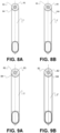
- Figures 8A and 8B show arm 2 and arm 2' of a first pair of arms 2, 2' of this embodiment of the panic bar device 100, wherein the operating shaft 81 is coupled to arm 2 and to arm 2' with a first angular orientation.
- arm 2 Upon coupling arm 2 to bearing assembly 1, in the standby state, arm 2 has an inclination with respect to the front surface 104 of the door 101 equal to angle ⁇ , as shown in Figure 7A .
- arm 2' upon coupling arm 2' to bearing assembly 1', in the standby state, arm 2' has an inclination with respect to the front surface 104 of the door 101 also equal to angle ⁇ , that is, once arms 2, 2' of the first pair of arms are coupled to respective bearing assemblies 1, 1', they are both positioned with respect to the front surface of the door 101 with the same inclination, angle ⁇ .
- Figures 9A and 9B show arm 2 and arm 2' of a second pair of arms 2, 2' of this embodiment of the panic bar device 100, wherein the operating shaft 81 is coupled to arm 2 and to arm 2' with a second angular orientation.
- arm 2 Upon coupling arm 2 to bearing assembly 1, in the standby state, arm 2 has an inclination with respect to the front surface 104 of the door 101 equal to angle ⁇ , as shown in Figure 7B .
- arm 2' has an inclination with respect to the front surface 104 of the door 101 also equal to angle ⁇ .
- the panic bar device 100 of this embodiment can be used with other pairs of arms 2, 2' in which as the angular orientation of the operating shaft 81 is varied with respect to the arms 2, 2' different inclinations will be obtained.
- arm 2 of each pair of arms 2, 2' is coupled to bearing assembly 1 from one end of the rotating shaft 21 and arm 2' of said pair of arms 2, 2' is coupled to bearing assembly 1' from another end of the rotating shaft 21.
- the angular orientation of the operating shaft 81 with respect to arm 2 and the angular orientation of the operating shaft 81 with respect to arm 2' must be such that arm 2 and arm 2' are symmetrical with respect to a plane of symmetry located between both arms 2, 2' and at the same distance from both when both arms 2, 2' are viewed in side view, as shown in Figures 8A and 8B , or in Figures 9A and 9B .
- the same panic bar device 100 can be used with different pairs of arms 2, 2' makes it possible that the same panic bar device 100 can be used with different locks existing on the market, such that depending on the characteristics of the lock to be used with the panic bar device 100 and the force that needs to be exerted on the pair of arms 2, 2' to open the lock, the pair of arms 2, 2' can be selected such that they have the suitable length and inclination with respect to the front surface 104 of the door 101.
- the first bearing assembly 1 will act on a lock installed on the first side or on the second side of the door 101, whereas the second bearing assembly 1' will not act on any lock.
- the first bearing assembly 1 which acts on the lock, comprises a bearing element 11 comprising a base plate 12 configured for being fixed to the front surface 104 of the door 101, a first side plate 13 attached to the base plate 12 on one of its sides, and a second side plate 13' attached to the base plate 12 on the opposite side facing the first side plate 13, as shown in Figure 11 .
- Each side plate 13, 13' comprises a bore 14, 14', both bores 14, 14' facing one another, and the rotating shaft 21 being housed in the bores 14, 14' of the side plates 13, 13'.
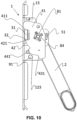
- the first bearing assembly 1 comprises at least one pushing element 41 coupled to the rotating shaft 21 and configured for rotating together with the rotating shaft 21, the pushing element 41 comprising a projection 42, as shown in Figure 10 .
- the first bearing assembly 1 comprises a lock actuating element 31 coupled to the base plate 12 configured for rotating about an axis perpendicular to the base plate 12 and acting on the lock, the actuating element 31 comprising a projection 32 configured for being pushed by the projection 42 of the pushing element 41, thus causing the rotation thereof.
- the pushing element 41 is configured for delimiting the angular travel of the panic bar 3 cooperating with a standby position stop 121 and with an end-of-travel stop 122.
- the second bearing assembly 1' which does not act on the lock, is identical to the first bearing assembly 1, which acts on the lock, without the lock actuating element 31.
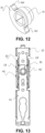
- Figure 12 shows the lock actuating element 31 of this embodiment of the panic bar device 100.
- the lock actuating element comprises a projection 32 which, in this embodiment extends radially and outwardly with respect to the shaft on which the lock actuating element 31 rotates.
- the rotating shaft 21 is configured for rotating with the arm 2, 2' of the panic bar device 100, such that when the bar 3 is pushed, the arms 2, 2' pivot with respect to the bearing assemblies 1, 1' causing the rotation of the rotating shaft 21 to which said arms 2, 2' are coupled.
- the rotating shaft 21 is coupled to the pushing element 41. Therefore, upon pushing the bar 3, the pushing element 41 rotates together with the rotating shaft 21, causing the rotation of the lock actuating element 31.
- the lock actuating element 31 has a square-shaped bore in which there is coupled a shaft which rotates together with the lock actuating element 31. Said shaft is coupled to the lock arranged in the door 101, such that upon rotation of the lock actuating element 31, it will act on the lock, such that the lock will allow the door to open.
- a sleeve 33 is arranged between the lock actuating element 31 and the base plate 12 to which said lock actuating element 31 is coupled, such that by means of the use of the sleeve 33 direct contact between the lock actuating element 31 and the base plate 12 is prevented.
- the base plate 12 comprises at least one side projection 18 on one of the sides of said base plate 12, the side projection 18 comprising the standby position stop 121 and the end-of-travel stop 122.
- the pushing element 41 comprises a standby projection 411 which, in the standby state of the panic bar device 100, cooperates with the standby position stop 121.
- the pushing element 41 comprises an end-of-travel projection 441 which cooperates with the end-of-travel stop 122 when the user pushes the bar 3 and the end of the angular travel thereof is reached.
- the bearing assembly 1, 1' comprises at least one additional detachable end-of-travel stop 123 delimiting a smaller travel than end-of-travel stop 122, the end-of-travel stop 122 being a fixed stop.
- the bar 3 presents a certain angular travel, and when said additional detachable end-of-travel stop 123 is located in the panic bar device 100, the bar 3 presents a smaller angular travel.
- the additional detachable end-of-travel stop 123 is a shaft 91 configured for being housed in facing bores 17, 17' arranged in the side plates 13, 13'.
- Figure 11 shows the shaft 91 of this embodiment, housed in the bores 17, 17' of the side plates 13, 13'.
- the pushing element 41 comprises an additional end-of-travel projection 431 which cooperates with the additional detachable end-of-travel stop 123 when the user pushes the bar 3, as shown in Figure 8 .
- the additional detachable end-of-travel stop 123 comprises a recess 92
- the bearing assembly 1, 1' comprises between the two side plates an elastic protrusion 73 configured for being housed in said recess 92 and fixing the axial position of said additional detachable travel stop 123.
- the bearing assembly 1, 1' comprises a guide element 71 positioned on the base plate 12 and coupled to the side plates 13, 13', the guide element 71 comprising the elastic protrusion 73.
- the guide element 71 is preferably manufactured in a plastic material.
- the guide element 71 is positioned on the base plate 12 and the lock actuating element 31, the lock actuating element 31 being coupled to the guide element 71.
- the guide element 71 of this embodiment of the panic bar device 100 comprises a plurality of flanges 72, and each of the side plates 13, 13' comprises at least two bores 16, such that the guide element 71 is coupled to the side plates 13, 13' when each flange 72 is introduced into its respective bore 16.
- the guide element 71 of this embodiment can be seen in Figure 3 , wherein the guide element 71 comprises four flanges 72, two flanges 72 on one side of the guide element 72, and two other flanges 72 on the other side.
- the side plates 13, 13' of this embodiment can be seen in Figure 12 , wherein the first side plate 13 comprises two bores 16, and the second side plate 13' also comprises two bores 16, such that the two flanges of one side of the guide element 72 are introduced into the two bores 16 of the first side plate 13, and the two flanges of the other side of the guide element 71 are introduced into the two bores 16 of the second side plate 13', the guide element 71 thus being coupled to the side plates 13, 13'.
- the operating shaft 81 comprises a fixing element 82 and pushing means 83 configured for pushing the fixing element 82 radially out of the operating shaft 81
- the rotating shaft 21 comprises a bore 23 on the periphery of the housing 22 in the radial direction, the fixing element 82 being configured for being housed in the bore 23 when the operating shaft 81 is introduced into the housing 22 and fixing the operating shaft 81 to the rotating shaft 21.
- the housing 22 comprises a contour, and the fixing element 82 at least partially protrudes from the contour of the operating shaft 81 when the operating shaft 81 is not introduced into the housing 22.
- the fixing element 82 is configured so that when it abuts with the contour of the housing 22 upon introducing the operating shaft 81 into the housing 22, it is retracted and is housed inside the operating shaft 81.
- the part of the fixing element 82 which protrudes from the operating shaft 81 when the latter is not introduced into the housing 22 preferably has a curved or planar upward surface which allows the fixing element 82 to be retracted upon abutting with the contour of the housing 22 during the introduction of the operating shaft 81 into the housing 22.
- the part of the fixing element 82 which protrudes from the operating shaft 81 may have another shape which allows the fixing element 82 to be retracted upon abutting with the contour of the housing 22 during the introduction of the operating shaft 81 into the housing 22.
- the fixing element 82 is facing the bore 23, the pushing means 83 push the fixing element 82 such that the fixing element 82 once again at least partially protrudes from the contour of the operating shaft 81, said part of the fixing element 82 which protrudes from the operating shaft 81 being housed in the bore 23, thereby fixing the operating shaft 81 to the rotating shaft 21.
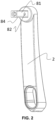
- Figure 2 shows an embodiment of the first arm 2 of the panic bar device 100, with the operating shaft 81 fixed to said arm 2.
- the operating shaft 81 can be fixed to the arm 2 by means of a screw, by means of adhesive, by means of welding, or by means of the use of other fixing means known in the state of the art.
- the panic bar device 100 of the invention shown in Figure 1 facilitates the installation thereof on the door 101 given that the arms do not need to be screwed to the corresponding bearing assembly 1, 1' to be fixed, but rather it is sufficient for them to be inserted until the fixing element 82 is fixed in the bore 23 of the housing 22 of the rotating shaft 21.
- the housing 22 of the rotating shaft 21 and the operating shaft 81 have a cross section configured so that the operating shaft 81 can be introduced into the housing 22 in a single position. This thereby prevents a person in charge of fixing the arm 2, 2' to bearing assembly 1, 1' from fixing the arm 2, 2' incorrectly, given that there is only one possible position in which the operating shaft 81 can be introduced into the housing 22.
- the cross section of the housing 22 of the rotating shaft 21 and of the operating shaft 81 is a regular polygon with a bevel 84 in one of the vertices of said polygon, as shown in Figures 1 and 4 .
- the rotating shaft 21 comprises an additional bore 23' on the periphery of the housing 22 in the radial direction, symmetrical to the bore 23 with respect to a plane perpendicular to a longitudinal axis of the rotating shaft 21 at the mid-point of said rotating shaft 21, such that when the operating shaft 81 is introduced into the rotating shaft 21 from a first end of the rotating shaft 21 the fixing element 82 is housed in the bore 23, and when the operating shaft 81 is introduced into the rotating shaft 21 from a second end of the rotating shaft 21 the fixing element 82 is housed in the additional bore 23'.
- the arm 2, 2' can be introduced into the first end of the rotating shaft 21, or into the second end of the rotating shaft 21, which enables being able to fix the bearing assembly 1, 1' on a first side or on a second side of the door 101. Furthermore, the panic bar device 100 of this embodiment prevents the person in charge of fixing the arm 2, 2' to bearing assembly 1, 1' from trying to fix the arm 2, 2' incorrectly, that is, trying to fix the arm 2, 2' in the bearing assembly 1, 1' that does not correspond to it.
- FIG. 5 shows a section view of this embodiment of the panic bar device 100, wherein the arm 2 has been introduced into the first end of the rotating shaft 21, the fixing element 82 of the operating shaft 81 being housed in the bore 23.
- the fixing element 82 is a pin.
- the pushing means 83 are a spring.
- the bore 23 on the periphery of the housing 22 in the radial direction is a through bore. It can be observed in Figure 5 that in this embodiment, the bore 23 communicates the housing 22 of the rotating shaft 21 with the outer surface of said rotating shaft 21.
- the projection 32 of the lock actuating element 31 is arranged in a first angular position, the projection 32 is pushed by the projection 42 of the pushing element 41, the lock actuating element 31 rotating in one direction, and if the projection 32 is arranged in a second angular position it is pushed by a projection 42' of an additional pushing element 41', the lock actuating element 31 rotating in the opposite direction.
- the lock actuating element 31 of this embodiment of the panic bar device 100 comprises a first standby position in which the projection 32 of the lock actuating element 31 is arranged in the first angular position, and a second standby position in which the projection 32 of the lock actuating element 31 is arranged in the second angular position.
- the projection 32 comprises a first contact surface 321 and a second contact surface 322, such that when the lock actuating element 31 is in the first standby position and the bar 3 is pushed, the pushing element 41 pushes the projection 32, contacting with the first contact surface 321.
- the additional pushing element 41' pushes the projection 32, contacting with the second contact surface 322.
- the first and second standby positions of the lock actuating element 31 are positions of the lock actuating element 31 in which the bar 3 of the panic bar device 100 is not being pushed.
- Figure 13 shows part of the first bearing assembly 1 of this embodiment of the panic bar device 100, wherein the lock actuating element 31 is in the first standby position.
- Figure 10 also shows this embodiment, wherein the lock actuating element 31 is in the first standby position, such that when the bar 3 is pushed the pushing element 41 pushes the projection 32 of the lock actuating element 31, rotating the lock actuating element 31 in one direction, for which purpose the pushing element 41 will contact with the first contact surface 321.
- the first bearing assembly 1 of this embodiment is configured for being arranged interchangeably on the first side or on the second side of the door 101, such that when the lock is arranged on the first side of the door 101, the lock actuating element 31 of the first bearing assembly 1, which acts on the lock, will be arranged in the first standby position shown in Figure 10 , such that when the bar 3 is pushed, the pushing element 41 will push the projection 32 of the lock actuating element, contacting with the contact surface 321, rotating the lock actuating element 31 in one direction, in the clockwise direction, acting on the lock and thus causing the door 101 to open.
- the lock actuating element 31 of the first bearing assembly 1, which acts on the lock will be arranged in the second standby position, such that when the bar 3 is pushed, the additional pushing element 41' will push the projection 32 of the lock actuating element 31, contacting with the contact surface 322, rotating the lock actuating element 31 in the opposite direction, that is, in the counter-clockwise direction, acting on the lock and thus causing the door 101 to open.
- the pushing element 41 and the additional pushing element 41' are coupled to the rotating shaft 21 and are configured for directly pushing the projection 32 of the lock actuating element 31.
- the rotating shaft 21 comprises at each of its ends four projections, and the pushing element 41 and the additional pushing element 41' each comprises a bore in which said projections are coupled, and after being riveted allow the rotating shaft 21 to be fixed to the pushing element 41 at one end and to the additional pushing element 41' at the other end.
- the projection 42 comprises a contact surface 421, such that when the lock actuating element 31 is in the first standby position and the bar 3 is pushed, the projection 42 of the pushing element 41 of the first bearing assembly 1, which acts on the lock, directly pushes the projection 32 of the lock actuating element 31, for which purpose the contact surface 421 of the projection 42 of the pushing element 41 pushes the first contact surface 321 of the lock actuating element 31.
- the projection 42' comprises a contact surface 421', such that when the lock actuating element 31 is in the second standby position and the bar 3 is pushed, the projection 42' of the additional pushing element 41' of the first bearing assembly 1, which acts on the lock, directly pushes the projection 32 of the lock actuating element 31, for which purpose the contact surface 421' of the projection 42' of the additional pushing element 41' pushes the second contact surface 322 of the lock actuating element 31.
- the bearing assembly 1, 1' of this embodiment of the panic bar device 100 is configured for being positioned with the same orientation regardless of whether it is arranged on the first side or on the second side of the door 101. Consequently, the person in charge of fixing the bearing assembly 1, 1' to the door 101 does not have to take into account whether the bearing assembly 1, 1' is to be fixed on the first side or on the second side of the door 101, given that the bearing assembly 1, 1' does not need to rotate or change its position depending on the side of the door 101 in which it is to be fixed.
- the lock actuating element 31 is arranged centered between the two side plates 13, 13', the projection 32 of said lock actuating element 31 being arranged close to the first side plate 13 when said lock actuating element 31 is arranged in the first standby position, said projection 32 being arranged close to the second side plate 13' when said lock actuating element 31 is arranged in the second standby position, the pushing element 41 being arranged close to the first side plate 13, and the additional pushing element 41' being arranged close to the second side plate 13'.
- the pushing element 41 and the additional pushing element 41' of this embodiment of the panic bar device 100 are arranged outside a demarcated area between the two side plates 13, 13', as observed in Figure 13 .
- the first side plate 13 and the second side plate 13' are arranged symmetrically with respect to a plane of symmetry parallel to the first side plate 13 and to the second side plate 13', said plane of symmetry being situated at the same distance from both side plates 13, 13'. Furthermore, the axis on which the lock actuating element 31 rotates, which axis is perpendicular to the base plate 12, is contained in said plane of symmetry.
- the bearing assembly 1, 1' of this embodiment of the panic bar device 100 comprises a calibrating element 51 configured for being coupled to the two side plates 13, 13' so that both side plates 13, 13' remain parallel to one another and perpendicular to the base plate 12. Since the calibrating element 51 is configured for keeping the first side plate 13 and the second side plate 13' parallel to one another, it prevents the occurrence of friction and accordingly friction between the pushing element 41 and the first side plate 13, and between the additional pushing element 41' and the second side plate 13' when the bar 3 is pushed, and accordingly, the pushing element 41 and the additional pushing element 41' rotate.
- the calibrating element 51 of this embodiment comprises a U-shaped projection 52 at each of its ends, each projection 52 comprising two bars 54 facing and attached to one another by means of an additional bar 56, and a gap 53 between both bars.
- Each side plate 13, 13' comprises a through bore 15, 15', such that the calibrating element 51 is introduced through both through bores 15, 15' and slides in until the side plates 13, 13' abut with the additional bar 56, such that each of the side plates 13, 13' is housed in the gap 53 between both bars 54 of each U-shaped projection 52, the calibrating element 51 thus being coupled to both side plates 13, 13'.
- Figure 3 shows the calibrating element 51
- Figure 6 shows the calibrating element 51 coupled to the two side plates 13, 13'.
- the bearing assembly of this embodiment of the panic bar device 100 comprises a sleeve 24 that is coaxial and external with respect to the rotating shaft 21, and a spring 61 arranged around the sleeve 24.
- the spring 61 is configured for returning the panic bar device 100 to the standby state.
- the calibrating element 51 comprises a projection 55 on which the spring 61 is held in place the spring 61 remaining tensioned, such that the calibrating element 51 is fixed to the side plates 13, 13' by the action of the spring 61.
- one of the ends of the spring 61 is fixed to the pushing element 41, and the other end of the spring 61 is fixed to the additional pushing element 41', such that when the pushing element 41 and the additional pushing element 41' rotate because the bar 3 of the panic device 100 has been pushed, the spring 61 is subjected to a torsional force, such that when said torsional force disappears because the bar 3 is no longer being pushed, the spring 61 returns the panic bar device 100 to the standby state.
- the spring 61 is secured to the projection 55 of the calibrating element 51, thus pushing the calibrating element 51 towards the side plates 13, 13' such that the additional bar 56 of each U-shaped projection 52 abuts with the side plates 13, 13'.
Landscapes
- Engineering & Computer Science (AREA)
- Structural Engineering (AREA)
- Mechanical Engineering (AREA)
- Business, Economics & Management (AREA)
- Emergency Management (AREA)
- Lock And Its Accessories (AREA)
- Steering Devices For Bicycles And Motorcycles (AREA)
- Train Traffic Observation, Control, And Security (AREA)
- Formation And Processing Of Food Products (AREA)
- Fish Paste Products (AREA)
- Devices For Checking Fares Or Tickets At Control Points (AREA)
- Pivots And Pivotal Connections (AREA)
Applications Claiming Priority (2)
| Application Number | Priority Date | Filing Date | Title |
|---|---|---|---|
| EP19383152 | 2019-12-19 | ||
| PCT/ES2020/070795 WO2021123478A1 (es) | 2019-12-19 | 2020-12-16 | Dispositivo de barra antipánico |
Publications (3)
| Publication Number | Publication Date |
|---|---|
| EP4080001A1 EP4080001A1 (en) | 2022-10-26 |
| EP4080001C0 EP4080001C0 (en) | 2024-01-10 |
| EP4080001B1 true EP4080001B1 (en) | 2024-01-10 |
Family
ID=74187326
Family Applications (1)
| Application Number | Title | Priority Date | Filing Date |
|---|---|---|---|
| EP20842591.8A Active EP4080001B1 (en) | 2019-12-19 | 2020-12-16 | Panic bar device |
Country Status (8)
| Country | Link |
|---|---|
| EP (1) | EP4080001B1 (pl) |
| CN (1) | CN114829722B (pl) |
| ES (1) | ES2971758T3 (pl) |
| IL (1) | IL294026B2 (pl) |
| MA (1) | MA58035B1 (pl) |
| MX (1) | MX2022006400A (pl) |
| PL (1) | PL4080001T3 (pl) |
| WO (1) | WO2021123478A1 (pl) |
Family Cites Families (25)
| Publication number | Priority date | Publication date | Assignee | Title |
|---|---|---|---|---|
| GB519937A (en) * | 1938-09-29 | 1940-04-10 | James Adams & Son Ltd | Improvements in or relating to panic bolts or emergency exit fastenings |
| SE356782B (pl) * | 1972-07-10 | 1973-06-04 | Bengtsson Sigurd W | |
| FR2613754B1 (fr) * | 1987-04-13 | 1990-12-21 | Peugeot | Dispositif a tirette de frise de commande du verrouillage ou deverrouillage d'une porte d'un vehicule automobile |
| FR2648502B1 (fr) * | 1989-06-20 | 1991-09-20 | Vachette Sa | Serrure antipanique et boitier pour une telle serrure |
| IT220330Z2 (it) * | 1990-12-19 | 1993-09-16 | Corbin | Dispositivo antipanico per uscita di emergenza |
| DE4201069C2 (de) * | 1992-01-17 | 2003-08-14 | Wilke Heinrich Hewi Gmbh | Getriebe für ein Türschloß, insbesondere ein Rauchschutztürschloß |
| US5364140A (en) * | 1993-04-08 | 1994-11-15 | Richard J. Bagan, Inc. | Door security device |
| ES2155291B1 (es) * | 1996-04-01 | 2001-12-01 | Talleres Escoriaza Sa | Barra antipanico con reversibilidad para puertas de emergencia. |
| AU6425500A (en) * | 1999-06-22 | 2001-01-09 | Hormann Kg Antriebstechnik | Locking device and door-drive device comprising the same, for a door operated bya motor assembly |
| DE60232946D1 (de) * | 2002-04-16 | 2009-08-27 | Cisa Spa | Antipanikstange für links oder rechts drehende Türen |
| DE102004012323B4 (de) * | 2004-03-11 | 2006-08-10 | Dorma Gmbh + Co. Kg | Paniktürenöffnungsvorrichtung |
| DE102005029452A1 (de) * | 2005-06-24 | 2006-12-28 | Hewi Heinrich Wilke Gmbh | Getriebe für einen Panikgriff oder eine Panikstange |
| CN201144569Y (zh) * | 2007-08-29 | 2008-11-05 | 四川江山铁路配件有限公司 | 机车应急门锁 |
| DE102009047852B4 (de) * | 2009-09-30 | 2011-07-07 | ASSA ABLOY Sicherheitstechnik GmbH, 72458 | Türüberwachungsvorrichtung |
| DE102009045440A1 (de) * | 2009-10-07 | 2011-04-14 | Bks Gmbh | Panikverschluss mit schwenkbarem Stangengriff |
| DE102012025514A1 (de) | 2012-09-13 | 2014-03-13 | Assa Abloy Sicherheitstechnik Gmbh | Beschlag mit Betätigungshandhabe für eine Tür, Fenster oder dergleich mit Adapterlagerplatte |
| EP2708688A1 (de) * | 2012-09-13 | 2014-03-19 | ASSA ABLOY Sicherheitstechnik GmbH | Griffstange mit Drehachse in identischer Höhe wie Drehhandhabe |
| DE102014007197B4 (de) * | 2014-05-16 | 2021-09-02 | SÜD-Metall Schließsysteme Leipzig GmbH | Getriebe für Paniktürverschluss |
| CN107109865B (zh) * | 2014-09-05 | 2019-07-09 | 汉普顿产品国际公司 | 可通过绕第一或第二轴线枢转致动器而操作的钥匙锁具 |
| EP3018272B1 (de) * | 2014-11-07 | 2018-11-07 | Wilh. Schlechtendahl & Söhne GmbH & Co. KG | Getriebeanordnung für eine Panikstange |
| ITUB20156022A1 (it) * | 2015-11-30 | 2017-05-30 | Leandro Cappellotto | Meccanismo di movimentazione di ante di mobili |
| EP3406829B1 (de) * | 2017-05-24 | 2019-07-03 | BKS GmbH | Türbeschlag für einen paniktürverschluss und paniktürverschluss |
| CN108741559A (zh) * | 2018-04-21 | 2018-11-06 | 张凡怡 | 一种可变角度旅行箱拉杆 |
| CN209443898U (zh) * | 2018-10-25 | 2019-09-27 | 太重煤机有限公司 | 拉手装置 |
| CN209637383U (zh) * | 2019-01-08 | 2019-11-15 | 佛山市戈诺尼金属制品有限公司 | 一种门拉手组件 |
-
2020
- 2020-12-16 MX MX2022006400A patent/MX2022006400A/es unknown
- 2020-12-16 WO PCT/ES2020/070795 patent/WO2021123478A1/es not_active Ceased
- 2020-12-16 IL IL294026A patent/IL294026B2/en unknown
- 2020-12-16 PL PL20842591.8T patent/PL4080001T3/pl unknown
- 2020-12-16 EP EP20842591.8A patent/EP4080001B1/en active Active
- 2020-12-16 CN CN202080084965.7A patent/CN114829722B/zh active Active
- 2020-12-16 MA MA58035A patent/MA58035B1/fr unknown
- 2020-12-16 ES ES20842591T patent/ES2971758T3/es active Active
Also Published As
| Publication number | Publication date |
|---|---|
| IL294026B2 (en) | 2025-09-01 |
| EP4080001C0 (en) | 2024-01-10 |
| MX2022006400A (es) | 2022-06-24 |
| ES2971758T3 (es) | 2024-06-06 |
| MA58035B1 (fr) | 2024-03-29 |
| IL294026B1 (en) | 2025-05-01 |
| IL294026A (en) | 2022-08-01 |
| WO2021123478A1 (es) | 2021-06-24 |
| PL4080001T3 (pl) | 2024-05-27 |
| CN114829722A (zh) | 2022-07-29 |
| CN114829722B (zh) | 2024-03-29 |
| EP4080001A1 (en) | 2022-10-26 |
Similar Documents
| Publication | Publication Date | Title |
|---|---|---|
| US6862845B2 (en) | Drop-catch mechanism for an overhead door | |
| WO1995003463A1 (en) | Shoot bolt mechanism | |
| CN114502810A (zh) | 指示器式门锁 | |
| NZ270233A (en) | Door lever assembly has breakaway lever with wedge release mechanism | |
| RU2728397C2 (ru) | Ручка для универсальной сборки | |
| RU2611287C2 (ru) | Привод тягового запирающего механизма, тяговый запирающий механизм с таким приводом, а также окно, дверь или подобное с таким тяговым запирающим механизмом | |
| WO2012045702A1 (en) | Device for manually controlling the unlocking and locking of the lock of a frame | |
| US11566454B2 (en) | Motor vehicle lock | |
| EP4080001B1 (en) | Panic bar device | |
| RU2664648C2 (ru) | Замок с механизмом срабатывания засова | |
| US4296956A (en) | Cam operated lock, particularly for doors | |
| CA1320839C (en) | Door locking arrangement | |
| JP6896257B2 (ja) | ヒンジアームダンパ機構 | |
| EP3839179B1 (en) | Support assembly of a panic bar device | |
| US11624219B2 (en) | Door lock adapter | |
| CZ300655B6 (cs) | Blokovací úchyt, zejména pro motorová vozidla | |
| CN115768007B (zh) | 锁具及具有锁具的led显示装置 | |
| CN113153013B (zh) | 执手换向机构和锁具 | |
| JPH07254343A (ja) | 回路遮断器の外部操作ハンドル装置 | |
| KR20010090823A (ko) | 아마추어 장치용 로터 장치 | |
| EP4491836B1 (en) | Handle return assembly and handle for a door or a window | |
| US4287734A (en) | Combination lock mechanism | |
| WO2021251895A1 (en) | Adapter for a locking device, and locking assembly comprising an adapter and a locking device | |
| ES1262256U (es) | Dispositivo de barra antipánico | |
| JPH0531199Y2 (pl) |
Legal Events
| Date | Code | Title | Description |
|---|---|---|---|
| STAA | Information on the status of an ep patent application or granted ep patent |
Free format text: STATUS: UNKNOWN |
|
| STAA | Information on the status of an ep patent application or granted ep patent |
Free format text: STATUS: THE INTERNATIONAL PUBLICATION HAS BEEN MADE |
|
| PUAI | Public reference made under article 153(3) epc to a published international application that has entered the european phase |
Free format text: ORIGINAL CODE: 0009012 |
|
| STAA | Information on the status of an ep patent application or granted ep patent |
Free format text: STATUS: REQUEST FOR EXAMINATION WAS MADE |
|
| 17P | Request for examination filed |
Effective date: 20220530 |
|
| AK | Designated contracting states |
Kind code of ref document: A1 Designated state(s): AL AT BE BG CH CY CZ DE DK EE ES FI FR GB GR HR HU IE IS IT LI LT LU LV MC MK MT NL NO PL PT RO RS SE SI SK SM TR |
|
| RIN1 | Information on inventor provided before grant (corrected) |
Inventor name: PENAGARIKANO IRAOLA, IZASKUN Inventor name: GONI URBIETA, FERNANDO Inventor name: OTEGI ODRIOZOLA, EDUARDO JESUS |
|
| DAX | Request for extension of the european patent (deleted) | ||
| RAV | Requested validation state of the european patent: fee paid |
Extension state: MA Effective date: 20220530 |
|
| P01 | Opt-out of the competence of the unified patent court (upc) registered |
Effective date: 20230831 |
|
| RIC1 | Information provided on ipc code assigned before grant |
Ipc: E05C 21/00 20060101ALN20230918BHEP Ipc: E05B 63/04 20060101ALI20230918BHEP Ipc: E05B 3/04 20060101ALI20230918BHEP Ipc: E05B 63/00 20060101ALI20230918BHEP Ipc: E05B 65/10 20060101AFI20230918BHEP |
|
| GRAP | Despatch of communication of intention to grant a patent |
Free format text: ORIGINAL CODE: EPIDOSNIGR1 |
|
| STAA | Information on the status of an ep patent application or granted ep patent |
Free format text: STATUS: GRANT OF PATENT IS INTENDED |
|
| INTG | Intention to grant announced |
Effective date: 20231027 |
|
| GRAS | Grant fee paid |
Free format text: ORIGINAL CODE: EPIDOSNIGR3 |
|
| GRAA | (expected) grant |
Free format text: ORIGINAL CODE: 0009210 |
|
| STAA | Information on the status of an ep patent application or granted ep patent |
Free format text: STATUS: THE PATENT HAS BEEN GRANTED |
|
| AK | Designated contracting states |
Kind code of ref document: B1 Designated state(s): AL AT BE BG CH CY CZ DE DK EE ES FI FR GB GR HR HU IE IS IT LI LT LU LV MC MK MT NL NO PL PT RO RS SE SI SK SM TR |
|
| REG | Reference to a national code |
Ref country code: GB Ref legal event code: FG4D |
|
| REG | Reference to a national code |
Ref country code: CH Ref legal event code: EP |
|
| REG | Reference to a national code |
Ref country code: DE Ref legal event code: R096 Ref document number: 602020024321 Country of ref document: DE |
|
| REG | Reference to a national code |
Ref country code: IE Ref legal event code: FG4D |
|
| U01 | Request for unitary effect filed |
Effective date: 20240131 |
|
| P04 | Withdrawal of opt-out of the competence of the unified patent court (upc) registered |
Effective date: 20240206 |
|
| U07 | Unitary effect registered |
Designated state(s): AT BE BG DE DK EE FI FR IT LT LU LV MT NL PT SE SI Effective date: 20240209 |
|
| REG | Reference to a national code |
Ref country code: MA Ref legal event code: VAGR Ref document number: 58035 Country of ref document: MA Kind code of ref document: B1 |
|
| REG | Reference to a national code |
Ref country code: ES Ref legal event code: FG2A Ref document number: 2971758 Country of ref document: ES Kind code of ref document: T3 Effective date: 20240606 |
|
| PG25 | Lapsed in a contracting state [announced via postgrant information from national office to epo] |
Ref country code: IS Free format text: LAPSE BECAUSE OF FAILURE TO SUBMIT A TRANSLATION OF THE DESCRIPTION OR TO PAY THE FEE WITHIN THE PRESCRIBED TIME-LIMIT Effective date: 20240510 |
|
| PG25 | Lapsed in a contracting state [announced via postgrant information from national office to epo] |
Ref country code: GR Free format text: LAPSE BECAUSE OF FAILURE TO SUBMIT A TRANSLATION OF THE DESCRIPTION OR TO PAY THE FEE WITHIN THE PRESCRIBED TIME-LIMIT Effective date: 20240411 |
|
| PG25 | Lapsed in a contracting state [announced via postgrant information from national office to epo] |
Ref country code: RS Free format text: LAPSE BECAUSE OF FAILURE TO SUBMIT A TRANSLATION OF THE DESCRIPTION OR TO PAY THE FEE WITHIN THE PRESCRIBED TIME-LIMIT Effective date: 20240410 Ref country code: HR Free format text: LAPSE BECAUSE OF FAILURE TO SUBMIT A TRANSLATION OF THE DESCRIPTION OR TO PAY THE FEE WITHIN THE PRESCRIBED TIME-LIMIT Effective date: 20240110 |
|
| PG25 | Lapsed in a contracting state [announced via postgrant information from national office to epo] |
Ref country code: RS Free format text: LAPSE BECAUSE OF FAILURE TO SUBMIT A TRANSLATION OF THE DESCRIPTION OR TO PAY THE FEE WITHIN THE PRESCRIBED TIME-LIMIT Effective date: 20240410 Ref country code: NO Free format text: LAPSE BECAUSE OF FAILURE TO SUBMIT A TRANSLATION OF THE DESCRIPTION OR TO PAY THE FEE WITHIN THE PRESCRIBED TIME-LIMIT Effective date: 20240410 Ref country code: IS Free format text: LAPSE BECAUSE OF FAILURE TO SUBMIT A TRANSLATION OF THE DESCRIPTION OR TO PAY THE FEE WITHIN THE PRESCRIBED TIME-LIMIT Effective date: 20240510 Ref country code: HR Free format text: LAPSE BECAUSE OF FAILURE TO SUBMIT A TRANSLATION OF THE DESCRIPTION OR TO PAY THE FEE WITHIN THE PRESCRIBED TIME-LIMIT Effective date: 20240110 Ref country code: GR Free format text: LAPSE BECAUSE OF FAILURE TO SUBMIT A TRANSLATION OF THE DESCRIPTION OR TO PAY THE FEE WITHIN THE PRESCRIBED TIME-LIMIT Effective date: 20240411 |
|
| REG | Reference to a national code |
Ref country code: DE Ref legal event code: R097 Ref document number: 602020024321 Country of ref document: DE |
|
| PG25 | Lapsed in a contracting state [announced via postgrant information from national office to epo] |
Ref country code: SM Free format text: LAPSE BECAUSE OF FAILURE TO SUBMIT A TRANSLATION OF THE DESCRIPTION OR TO PAY THE FEE WITHIN THE PRESCRIBED TIME-LIMIT Effective date: 20240110 |
|
| PG25 | Lapsed in a contracting state [announced via postgrant information from national office to epo] |
Ref country code: CZ Free format text: LAPSE BECAUSE OF FAILURE TO SUBMIT A TRANSLATION OF THE DESCRIPTION OR TO PAY THE FEE WITHIN THE PRESCRIBED TIME-LIMIT Effective date: 20240110 |
|
| PG25 | Lapsed in a contracting state [announced via postgrant information from national office to epo] |
Ref country code: SK Free format text: LAPSE BECAUSE OF FAILURE TO SUBMIT A TRANSLATION OF THE DESCRIPTION OR TO PAY THE FEE WITHIN THE PRESCRIBED TIME-LIMIT Effective date: 20240110 |
|
| PG25 | Lapsed in a contracting state [announced via postgrant information from national office to epo] |
Ref country code: SM Free format text: LAPSE BECAUSE OF FAILURE TO SUBMIT A TRANSLATION OF THE DESCRIPTION OR TO PAY THE FEE WITHIN THE PRESCRIBED TIME-LIMIT Effective date: 20240110 Ref country code: SK Free format text: LAPSE BECAUSE OF FAILURE TO SUBMIT A TRANSLATION OF THE DESCRIPTION OR TO PAY THE FEE WITHIN THE PRESCRIBED TIME-LIMIT Effective date: 20240110 Ref country code: RO Free format text: LAPSE BECAUSE OF FAILURE TO SUBMIT A TRANSLATION OF THE DESCRIPTION OR TO PAY THE FEE WITHIN THE PRESCRIBED TIME-LIMIT Effective date: 20240110 Ref country code: CZ Free format text: LAPSE BECAUSE OF FAILURE TO SUBMIT A TRANSLATION OF THE DESCRIPTION OR TO PAY THE FEE WITHIN THE PRESCRIBED TIME-LIMIT Effective date: 20240110 |
|
| PLBE | No opposition filed within time limit |
Free format text: ORIGINAL CODE: 0009261 |
|
| STAA | Information on the status of an ep patent application or granted ep patent |
Free format text: STATUS: NO OPPOSITION FILED WITHIN TIME LIMIT |
|
| 26N | No opposition filed |
Effective date: 20241011 |
|
| U20 | Renewal fee for the european patent with unitary effect paid |
Year of fee payment: 5 Effective date: 20241121 |
|
| P05 | Withdrawal of opt-out of the competence of the unified patent court (upc) changed |
Free format text: CASE NUMBER: APP_6770/2024 Effective date: 20240209 |
|
| PGFP | Annual fee paid to national office [announced via postgrant information from national office to epo] |
Ref country code: ES Payment date: 20250120 Year of fee payment: 5 |
|
| PG25 | Lapsed in a contracting state [announced via postgrant information from national office to epo] |
Ref country code: MC Free format text: LAPSE BECAUSE OF FAILURE TO SUBMIT A TRANSLATION OF THE DESCRIPTION OR TO PAY THE FEE WITHIN THE PRESCRIBED TIME-LIMIT Effective date: 20240110 |
|
| REG | Reference to a national code |
Ref country code: CH Ref legal event code: PL |
|
| U1N | Appointed representative for the unitary patent procedure changed after the registration of the unitary effect |
Representative=s name: GALBAIAN S.COOP.; ES |
|
| GBPC | Gb: european patent ceased through non-payment of renewal fee |
Effective date: 20241216 |
|
| PG25 | Lapsed in a contracting state [announced via postgrant information from national office to epo] |
Ref country code: GB Free format text: LAPSE BECAUSE OF NON-PAYMENT OF DUE FEES Effective date: 20241216 |
|
| PG25 | Lapsed in a contracting state [announced via postgrant information from national office to epo] |
Ref country code: CH Free format text: LAPSE BECAUSE OF NON-PAYMENT OF DUE FEES Effective date: 20241231 |
|
| PG25 | Lapsed in a contracting state [announced via postgrant information from national office to epo] |
Ref country code: IE Free format text: LAPSE BECAUSE OF NON-PAYMENT OF DUE FEES Effective date: 20241216 |
|
| VSFP | Annual fee paid to validation state [announced via postgrant information from national office to epo] |
Ref country code: MA Payment date: 20241209 Year of fee payment: 5 |
|
| U20 | Renewal fee for the european patent with unitary effect paid |
Year of fee payment: 6 Effective date: 20251118 |
|
| PGFP | Annual fee paid to national office [announced via postgrant information from national office to epo] |
Ref country code: PL Payment date: 20251117 Year of fee payment: 6 |
|
| VSFP | Annual fee paid to validation state [announced via postgrant information from national office to epo] |
Ref country code: MA Payment date: 20251226 Year of fee payment: 6 |