EP4079997B1 - Covering for an opening in a building and lock sensor assembly - Google Patents
Covering for an opening in a building and lock sensor assembly Download PDFInfo
- Publication number
- EP4079997B1 EP4079997B1 EP22168905.2A EP22168905A EP4079997B1 EP 4079997 B1 EP4079997 B1 EP 4079997B1 EP 22168905 A EP22168905 A EP 22168905A EP 4079997 B1 EP4079997 B1 EP 4079997B1
- Authority
- EP
- European Patent Office
- Prior art keywords
- panel
- locking member
- sensor
- locked
- sensor module
- Prior art date
- Legal status (The legal status is an assumption and is not a legal conclusion. Google has not performed a legal analysis and makes no representation as to the accuracy of the status listed.)
- Active
Links
Images




Classifications
-
- E—FIXED CONSTRUCTIONS
- E05—LOCKS; KEYS; WINDOW OR DOOR FITTINGS; SAFES
- E05B—LOCKS; ACCESSORIES THEREFOR; HANDCUFFS
- E05B63/00—Locks or fastenings with special structural characteristics
- E05B63/0052—Locks mounted on the "frame" cooperating with means on the "wing"
-
- E—FIXED CONSTRUCTIONS
- E05—LOCKS; KEYS; WINDOW OR DOOR FITTINGS; SAFES
- E05B—LOCKS; ACCESSORIES THEREFOR; HANDCUFFS
- E05B45/00—Alarm locks
- E05B45/06—Electric alarm locks
-
- E—FIXED CONSTRUCTIONS
- E05—LOCKS; KEYS; WINDOW OR DOOR FITTINGS; SAFES
- E05B—LOCKS; ACCESSORIES THEREFOR; HANDCUFFS
- E05B41/00—Locks with visible indication as to whether the lock is locked or unlocked
-
- E—FIXED CONSTRUCTIONS
- E05—LOCKS; KEYS; WINDOW OR DOOR FITTINGS; SAFES
- E05B—LOCKS; ACCESSORIES THEREFOR; HANDCUFFS
- E05B15/00—Other details of locks; Parts for engagement by bolts of fastening devices
- E05B15/02—Striking-plates; Keepers; Bolt staples; Escutcheons
- E05B15/0205—Striking-plates, keepers, staples
- E05B15/021—Strikers having multiple positions for the bolt
-
- E—FIXED CONSTRUCTIONS
- E05—LOCKS; KEYS; WINDOW OR DOOR FITTINGS; SAFES
- E05C—BOLTS OR FASTENING DEVICES FOR WINGS, SPECIALLY FOR DOORS OR WINDOWS
- E05C17/00—Devices for holding wings open; Devices for limiting opening of wings or for holding wings open by a movable member extending between frame and wing; Braking devices, stops or buffers, combined therewith
- E05C17/02—Devices for holding wings open; Devices for limiting opening of wings or for holding wings open by a movable member extending between frame and wing; Braking devices, stops or buffers, combined therewith by mechanical means
- E05C17/46—Devices for holding wings open; Devices for limiting opening of wings or for holding wings open by a movable member extending between frame and wing; Braking devices, stops or buffers, combined therewith by mechanical means in which the wing or a member fixed thereon is engaged by a movable fastening member in a fixed position; in which a movable fastening member mounted on the wing engages a stationary member
- E05C17/48—Devices for holding wings open; Devices for limiting opening of wings or for holding wings open by a movable member extending between frame and wing; Braking devices, stops or buffers, combined therewith by mechanical means in which the wing or a member fixed thereon is engaged by a movable fastening member in a fixed position; in which a movable fastening member mounted on the wing engages a stationary member comprising a sliding securing member
-
- E—FIXED CONSTRUCTIONS
- E05—LOCKS; KEYS; WINDOW OR DOOR FITTINGS; SAFES
- E05C—BOLTS OR FASTENING DEVICES FOR WINGS, SPECIALLY FOR DOORS OR WINDOWS
- E05C9/00—Arrangements of simultaneously actuated bolts or other securing devices at well-separated positions on the same wing
- E05C9/02—Arrangements of simultaneously actuated bolts or other securing devices at well-separated positions on the same wing with one sliding bar for fastening when moved in one direction and unfastening when moved in opposite direction; with two sliding bars moved in the same direction when fastening or unfastening
-
- E—FIXED CONSTRUCTIONS
- E05—LOCKS; KEYS; WINDOW OR DOOR FITTINGS; SAFES
- E05B—LOCKS; ACCESSORIES THEREFOR; HANDCUFFS
- E05B45/00—Alarm locks
- E05B45/06—Electric alarm locks
- E05B2045/065—Switch or sensor type used in alarm locks
- E05B2045/0665—Magnetic switches, e.g. reed- or hall-switch
-
- E—FIXED CONSTRUCTIONS
- E05—LOCKS; KEYS; WINDOW OR DOOR FITTINGS; SAFES
- E05B—LOCKS; ACCESSORIES THEREFOR; HANDCUFFS
- E05B47/00—Operating or controlling locks or other fastening devices by electric or magnetic means
- E05B2047/0048—Circuits, feeding, monitoring
- E05B2047/0067—Monitoring
- E05B2047/0068—Door closed
-
- E—FIXED CONSTRUCTIONS
- E05—LOCKS; KEYS; WINDOW OR DOOR FITTINGS; SAFES
- E05B—LOCKS; ACCESSORIES THEREFOR; HANDCUFFS
- E05B47/00—Operating or controlling locks or other fastening devices by electric or magnetic means
- E05B2047/0048—Circuits, feeding, monitoring
- E05B2047/0067—Monitoring
- E05B2047/0069—Monitoring bolt position
-
- E—FIXED CONSTRUCTIONS
- E05—LOCKS; KEYS; WINDOW OR DOOR FITTINGS; SAFES
- E05B—LOCKS; ACCESSORIES THEREFOR; HANDCUFFS
- E05B47/00—Operating or controlling locks or other fastening devices by electric or magnetic means
- E05B2047/0094—Mechanical aspects of remotely controlled locks
-
- E—FIXED CONSTRUCTIONS
- E05—LOCKS; KEYS; WINDOW OR DOOR FITTINGS; SAFES
- E05C—BOLTS OR FASTENING DEVICES FOR WINGS, SPECIALLY FOR DOORS OR WINDOWS
- E05C9/00—Arrangements of simultaneously actuated bolts or other securing devices at well-separated positions on the same wing
- E05C9/18—Details of fastening means or of fixed retaining means for the ends of bars
- E05C9/1808—Keepers
-
- E—FIXED CONSTRUCTIONS
- E05—LOCKS; KEYS; WINDOW OR DOOR FITTINGS; SAFES
- E05C—BOLTS OR FASTENING DEVICES FOR WINGS, SPECIALLY FOR DOORS OR WINDOWS
- E05C9/00—Arrangements of simultaneously actuated bolts or other securing devices at well-separated positions on the same wing
- E05C9/18—Details of fastening means or of fixed retaining means for the ends of bars
- E05C9/1825—Fastening means
- E05C9/1833—Fastening means performing sliding movements
- E05C9/185—Fastening means performing sliding movements parallel with actuating bar
-
- E—FIXED CONSTRUCTIONS
- E05—LOCKS; KEYS; WINDOW OR DOOR FITTINGS; SAFES
- E05Y—INDEXING SCHEME ASSOCIATED WITH SUBCLASSES E05D AND E05F, RELATING TO CONSTRUCTION ELEMENTS, ELECTRIC CONTROL, POWER SUPPLY, POWER SIGNAL OR TRANSMISSION, USER INTERFACES, MOUNTING OR COUPLING, DETAILS, ACCESSORIES, AUXILIARY OPERATIONS NOT OTHERWISE PROVIDED FOR, APPLICATION THEREOF
- E05Y2900/00—Application of doors, windows, wings or fittings thereof
- E05Y2900/10—Application of doors, windows, wings or fittings thereof for buildings or parts thereof
- E05Y2900/13—Type of wing
- E05Y2900/132—Doors
-
- G—PHYSICS
- G08—SIGNALLING
- G08B—SIGNALLING SYSTEMS, e.g. PERSONAL CALLING SYSTEMS; ORDER TELEGRAPHS; ALARM SYSTEMS
- G08B13/00—Burglar, theft or intruder alarms
- G08B13/02—Mechanical actuation
- G08B13/08—Mechanical actuation by opening, e.g. of door, of window, of drawer, of shutter, of curtain, of blind
-
- G—PHYSICS
- G08—SIGNALLING
- G08B—SIGNALLING SYSTEMS, e.g. PERSONAL CALLING SYSTEMS; ORDER TELEGRAPHS; ALARM SYSTEMS
- G08B25/00—Alarm systems in which the location of the alarm condition is signalled to a central station, e.g. fire or police telegraphic systems
- G08B25/008—Alarm setting and unsetting, i.e. arming or disarming of the security system
Definitions
- the present invention concerns coverings for buildings, such as doors and windows. More particularly, this invention concerns a covering for an opening in a building and a sensor assembly configured to be able to sense the position of a locking member of the covering for the building. The invention also concerns methods for installing a sensor assembly on a covering for a building.
- a window may be lockable in a vented configuration in which the window is partially open.
- An example of such a window system 100 is shown in FIG. 1 and FIG. 2 .
- the window system 100 comprises a window 101 hinge mounted to a window frame 102.
- the window 101 comprises a movably mounted elongate locking rod 103 which is coupled to a handle of the panel (not shown) at a first end and which comprises a locking member 105 which projects from the locking rod 103 at a second end.
- the window frame 102 comprises a keep 107 formed with a first channel 109 and a second channel 111 for receiving the locking member 105.
- the window 101 is lockable in a fully closed position, shown in FIG. 1 , by moving the window 101 to a closed position and then moving the handle of the window 101 to a locked position to move the locking member 105 into the first channel 109 of the keep 107.
- the window 101 is also lockable in a vented position, shown in FIG. 2 , in which the window is partially open by moving the window 101 so that the locking member 105 is aligned with the second channel 109 of the keep 107 and then moving the handle of the window 101 to a locked position to move the locking member 105 into the second channel 109.
- window systems are well known.
- Door systems having similar functionality also exist.
- Some prior art systems which are able to provide a remote user with information regarding the locked status of a door or window, such as those disclosed in GB2563060A and in WO2018/220384A1 , provide that information based on the position of a locking member but do not take into account the position of the window or door. Such systems may not be suitable for door or window arrangements where a locking member might get moved to a locked position when the door or window is not in a closed position because the window or door may be incorrectly determined to be locked when in fact it is not.
- WO 2016/012520 A1 discloses a window status sensor system which provides a signal concerning the position of the locking rod and the associated locking lugs, rather than merely monitoring the position of the window sash and/or the locking handle etc.
- the system comprises an induction sensor in which an electrical signal is generated due to the presence of the locking lug adjacent to the sensor within a keep. Accordingly, this feedback provides positive reassurance that the locking lugs are actually in an engaged/locked position.
- WO 2018/055398 A1 discloses a system for detecting the position of at least one moveable element of a window or door.
- the system comprises at least one sensor for sensing a magnetic field and processor means configured to receive output signals associated with the sensed magnetic and to determine the position of the at least one moveable element.
- WO2019/077366A1 discloses a lock system that detects the locked status of a door from the magnetic field provided by a magnetic key.
- the present invention seeks to mitigate the above-mentioned problems.
- the present invention provides, according to a first aspect, a covering for an opening in a building and a sensor assembly, wherein the covering comprises a panel, a frame member, and wherein the sensor assembly comprises a sensor module housing two inductive sensors and a transmitter, wherein one of the panel or frame member comprises a locking member and the sensor module is positioned on the other one of the panel or frame member, wherein the panel is moveable relative to the frame member between an open position and a closed position, and the panel is moveable to an intermediate position between the open position and the closed position.
- the locking member is moveable to a first locked position when the panel is in the closed position to lock the panel in the closed position.
- the locking member is moveable to a second locked position when the panel is in the intermediate position to lock the panel in the intermediate position.
- the sensor module is configured to sense the position of the locking member.
- the transmitter is configured to transmit a first signal indicating that the locking member is sensed to be in the first locked position.
- the transmitter is configured to transmit a second signal indicating that the locking member is sensed to be in the second locked position.
- the one of the panel or frame member comprising the locking member further comprises a metallic member that is coupled to the movement of the locking member.
- the sensors are configured to sense the proximity of the metallic member and to provide signals indicative of the proximity of the metallic member.
- the sensor assembly is configured to determine whether the panel is locked in the closed position or locked in the intermediate position by comparing the signals provided by each of the two sensors to reference values.
- the sensor module is attached to the panel or frame via a mount, that is fixed to the panel or frame.
- the sensor module comprises formations configured to interlock with the mount to hold the module in place upon the panel or frame.
- the sensor assembly By sensing that the locking member is in the first locked position, the sensor assembly is effectively able to determine if the panel is locked in the closed position, and to transmit a signal indicating the locked status of the panel to an end user, for example.
- the sensor assembly may determine that the panel is in an unlocked configuration if the locking member is not sensed to be in the first locked position.
- An unlocked configuration should be understood to correspond to a configuration in which the panel is able to be freely opened and closed by someone trying to gain access to the building.
- the panel may be a door leaf and the frame member may form a jamb or other part of a door frame.
- the panel may be a window and the frame member may form part of a window frame. In some embodiments, the frame member may form part of the structure of the building itself.
- the signal may be a wireless signal.
- the signal may be an RF, Bluetooth ⁇ RTM>, or WIFI signal.
- the signal may be sent via a wired connection of the sensor assembly.
- the locking member is the member of the panel or frame member which engages with the other one of the panel or frame member to lock to panel in position with respect to the frame member.
- the sensor assembly may be configured to sense the position of the locking member itself.
- the locking member may be a bolt or paddle that is moveable into and out of a keep.
- the locking member may alternatively be a cam.
- the sensor assembly may be configured to sense the position of the bolt, paddle, or cam within the keep.
- the sensor assembly may be configured to sense the position of the pin in order to determine the position of the bolt.
- the sensor assembly may be configured to sense the position of a handle or other member for actuating the locking member.
- the invention thereby provides an arrangement in which the locked status of a covering for a building, such as a door or window, is determined from the both the position of the locking member and the panel.
- This is advantageous over systems which sense only the position of the panel because if the panel is closed but not locked in the closed position, the system may incorrectly determine that the panel is locked in the closed position.
- the invention is advantageous over systems which sense only the position of the locking member because if the locking member is in a locked position but the panel is not in a closed position, the system may incorrectly determine that the panel is locked in the closed position.
- the lock status is transmitted to provide information regarding the lock status to a third party. For example, the occupier of a house may wish to know if a window or door of the house is open or closed.
- the transmitter when the position of the locking member is sensed to be in the second locked position, the transmitter is configured to transmit a second signal indicating that the locking member is sensed to be in the second locked position.
- the sensor assembly is effectively configured to determine that the panel is locked in the intermediate position by sensing that the locking member is in the second locked position.
- the intermediate position corresponds to a position in which a door or window is partially open, such a position may be referred to as a "vented position". Therefore the sensor assembly is configured to not only transmit a signal indicating that the panel is locked, but also in which particular configuration it is locked.
- an occupier of a house may wish to know if a window has been locked in a vented position in which there may be water ingress through the window.
- the signal may be transmitted to an end user's smart device, such as a smart phone, for example.
- the locking member may be manually moveable into the first and/or second locked position.
- the door or window arrangement may comprise a handle or other actuation member for manually moving the locking member into the first and/or second locked position.
- the covering may be provided with a resilient biasing member that moves the locking member into the first and/or second locked position.
- a handle or other actuation member may be provided for moving the locking member out of the first and/or second locked position.
- the sensor assembly may be configured to determine that the panel is in an unlocked configuration if the sensed position of the locking member does not correspond to the first locked configuration or the second locked configuration.
- the sensor assembly may be configured to transmit a wireless signal indicating that the panel is unlocked if the sensed position of the locking member does not correspond to the first locked configuration or the second locked configuration.
- first set of reference values which correspond to the expected sensor readings when the locking member is in the first locked position.
- second set of reference values which correspond to the expected sensor readings when the locking member is in the second locked position.
- the reference values may be stored on a memory of the sensor assembly. The reference values may have been obtained during a calibration process performed when the sensor assembly was fitted to the covering. Alternatively, the reference values may be generic and stored in a memory of the sensor assembly during the manufacturing process.
- the two sensors may be arranged along an axis such that, when the panel is moved between the open and closed position, the locking member and sensors move relative to one another along the axis.
- the sensors may, for example, be aligned with the channels of a keep of the other one of the panel or frame member.
- the covering may have a width dimension and a height dimension in a plane defined by an opening in a building.
- the covering may have a thickness dimension in a direction perpendicular to the width and height dimension.
- the axis may be parallel to the width direction.
- the two sensors may be arranged along a direction defined by the thickness of the panel or frame member.
- the sensor module provides the sensor(s) and a transmitter in a convenient package for mounting to a door panel, window, or frame.
- the transmitter by be configured to transmit a wired and/or wireless signal.
- Such an arrangement may be easily mounted to the covering in order to provide the covering with a lock sensing arrangement.
- the sensor module may also contain batteries configured to power the sensor module.
- the sensor module may be configured to receive power from an external power supply.
- the sensor module may have a length, a width, and a thickness.
- the length, width, and thickness dimensions may be no greater than 150 millimetres x 50 millimetres x 10 millimetres.
- the two sensors may be positioned adjacent one another across the width of the sensor assembly.
- the sensor module may be configured to be positioned such that its width direction aligns with the thickness direction of the covering.
- the wireless transmitter may be configured to emit a Bluetooth signal.
- the wireless transmitter may be wirelessly connected to the internet and configured to transmit the signal(s) to an end user via the internet.
- the skilled person will be aware of a variety of suitable wireless transmitters suitable to wirelessly transmit information regarding the locked status of the covering, and it should be understood that the invention is not limited to use of a specific type.
- the mount may be fixed to the frame or panel with fasteners, such as screws.
- the mount may be adhesively bonded to the frame or panel.
- the sensor assembly may comprise a hub configured to be positioned remotely of the sensor(s).
- the sensor assembly may be configured to transmit signals to the hub indicating the sensed position of the locking member.
- the hub may be configured to transmit the first signal and, optionally, second signal.
- the sensors may be in wired or wireless connection with the hub.
- the hub may be configured to be connected with a plurality of other sensor arrangements configured to sense the locked status of a plurality of coverings.
- There may be a plurality of sensor assemblies mounted to a respective plurality of coverings of a building.
- a building may have multiple doors and windows each comprising a sensor assembly, and each sensor assembly may be in wireless or wired connection with a central hub.
- the hub may be configured to receive the wireless signals from the sensors and to send information regarding the locked status of the doors and windows to an end user.
- the information may be sent to a third party electronic device (for example, a smartphone, tablet, or other "smart" device) via the internet.
- a third party electronic device for example, a smartphone, tablet, or other "smart" device
- a method of installing a sensor assembly on a covering of an opening of a building to provide a covering for an opening in a building and a sensor assembly in accordance with the first aspect of the invention comprises the steps of attaching a sensor module to one of the panel or a frame of the covering, moving the panel to a closed position, moving a locking member of the other one of the panel or a frame to a first locked position to lock the panel in the closed position, when the locking member is in the first locked position, sensing using the sensors of the sensor module, the position of a metallic member that is coupled to movement of the locking member, storing the sensor readings as a first calibration reading in a memory of the sensor assembly.
- the method may comprise the additional steps of sensing the position of the metallic member to obtain sensor readings from the sensors, comparing the sensor readings against the first calibration reading, and if the sensor readings are equal to the calibration reading then using the transmitter of the sensor module to transmit a signal indicating that the locking member is sensed to be in the first locked position.
- the sensor readings may be determined to be equal to the calibration reading if the sensor readings are within a prescribed tolerance of the calibration reading. For example, the sensor readings may be determined to be equal to the calibration reading if the sensor readings are within 10% of the calibration reading.
- the method may also comprise the steps of moving the panel to an intermediate position, between an open position of the panel and the closed position of the panel, moving the locking member of the covering to the second locked position to lock the panel in the intermediate position, sensing, using the sensors of the sensor module, the position of the metallic member when the locking member is in the second locked position, storing the sensor readings as a second calibration reading in a memory of the sensor assembly.
- the method may comprise the additional steps of sensing the position of the metallic member using the sensors of the sensor module, comparing the sensor readings against the second calibration reading, and if the sensor readings are equal to the second calibration reading then using the transmitter of the sensor module to transmit a signal indicating that the locking member is sensed to be in the second locked position.
- the method may comprise the steps of using the transmitter of the sensor module to transmit a signal indicating that the locking member is sensed to be in an unlocked position.
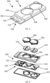
- a window or door can be fitted with the sensor module 500 that is shown in FIG. 3 in order provide a sensing functionality that is able to determine the locked status of the door or window.
- the sensor module 500 comprises a rectangular circuit board 520 which can be seen in the exploded view of the sensor module 500 that is shown in FIG. 4 .
- the circuit board comprises a sensor array 528, which is made up of a first inductive sensor 521 and a second inductive sensor 522 positioned adjacent one another across the width of the circuit board 520.
- the circuit board also comprises battery ports 523 for batteries 524 to power the circuit board 520.
- the other components of the circuit board 520 are shown schematically in FIG. 5 .
- the sensors 521, 522 and batteries 524 are connected to a processor 525, and the circuit board also comprises a wireless transmitter 526 and memory 527 which are also connected to the processor 525.
- the circuit board 520 is contained within a housing 501 having a main body 503 in the form of an elongate box which is dimensioned to contain the part of the circuit board 520 which holds the batteries 524, and which is formed with apertures 504 via which the batteries 524 can be inserted or removed.
- the apertures 504 are covered by lids 506.
- the housing 501 also comprises a lip section 505 that extends from an end of the main body 503 and which is dimensioned to contain the part of the circuit board which has the sensor array 528.
- the housing 501 is sealed by a base 507.
- the base 507 is formed with two mushroom shaped mounting members 508 which project from the surface of the base as shown in
- the sensor module 500 can be fitted to a window system as shown in FIG. 1 and FIG. 2 via a mount 600.
- a mount 600 is shown as screw-fixed to a window frame 202 in FIG. 6 .
- the mount 600 comprises a rectangular plate 601 formed with apertures 602 configured to interlock with the mushroom shaped mounting members 508 of the sensor module 500.
- the module 500 is mounted to the window frame 202 such that is positioned as schematically shown in FIG. 7 and FIG. 9 .
- the first sensor 521 is substantially aligned with the first channel 209 and such that the second sensor 522 is substantially aligned with the second channel 211, the first sensor 521 and second sensor 522 thereby being arranged along an axis X such that, when the panel is moved between the open and closed position, the locking member moves along the axis X relative to the first sensor 521 and the second sensor 522.
- the axis X is substantially parallel to a thickness direction t of the window frame 202.
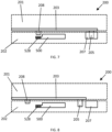
- FIG. 7 shows a portion of a window system 200 which is substantially identical to the window system 100 shown in FIG. 1 and FIG. 2 .
- the sensor module 500 is mounted to the window frame 202 such that when the window 201 is in a close or vented position, the sensor module is located directly adjacent the locking rod 203.
- the locking rod 203 has been fitted with a steel pin 208 at a position on the locking rod 203 such that when the locking member 205 is located within the keep 207, the steel pin is directly adjacent the sensor array 528 of the sensor module 500.
- the steel pin is moved away from the sensor array 528, as shown in FIG. 8 .
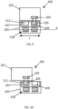
- FIG. 9 shows a schematic cross-sectional view of the window system 200 with the window in a fully closed and locked configuration in which the locking member 205 is located within the first channel 209 of the keep 207. In this configuration the steel pin 208 which is attached to the locking member is located directly adjacent the first sensor 521.
- FIG. 10 shows a schematic cross-sectional view of the window system 200 with the window in a vented and locked configuration in which the locking member 205 is located within the second channel 211 of the keep 207. In this configuration the steel pin 208 which is attached to the locking member 203 is located directly adjacent the second sensor 522.
- the sensors 521, 522 are able to sense the proximity of the steel pin 208 and each provide a sensor reading which is determined by the proximity of the steel pin 208 to the respective sensor 521, 522.
- the sensor module 500 is configured to be able to determine in which locked configuration the window system 200 is in by comparing the instantaneous sensor readings to a set of baseline sensor readings which are obtained during a calibration process which is performed when the sensor module 500 is installed in the window system 200.
- step 1000 the window 201 is moved to the fully closed position and the window 200 is locked by moving the locking member 205 into the first channel 209. At this stage the window is in the configuration shown in FIG. 9 .
- step 1001 a set sensor readings corresponding to a "closed and locked state” are taken and stored in the memory 527 of the sensor module 500.
- step 1002 the window 201 is moved to a vented position and the window 200 is locked by moving the locking member into the second channel 211. At this stage the window 200 is in the configuration shown in FIG. 10 .
- step 1003 a second set sensor readings corresponding to a "vented and locked state" are taken and stored in the memory 527 of the sensor module 500.
- the sensor module 500 forms part of a lock sensing system 400 which is shown schematically in FIG. 12 .
- the lock sensing system 400 also comprises a central hub 401 to which the sensor module 500 is wirelessly connected. While this embodiment of the invention is being described with reference to a single sensor module 500, the central hub 401 is configured to be connectable to multiple sensor modules so that multiple windows and/or doors of a building can be provided with smart functionality.
- the central hub is wirelessly connected to the internet via a router 700 so that the central hub can communicate with an electronic device 800 (for example, a smart phone or tablet) of an end user.
- an electronic device 800 for example, a smart phone or tablet
- the lock sensing system 400 is configured to provide the electronic device 800 of the end user with information about the locked status of the window system using a process that is shown schematically in Figure 13 .
- the sensors 521, 522 of the sensor module 500 each provide a sensor reading to the processor 525.
- the sensor reading is compared to the "vented and locked state” sensor reading and to the "closed and locked state” sensor reading, which were stored in the memory 527 of the sensor module 500 during the calibration process. If the sensor readings match the "closed and locked state” calibration readings, then the window 200 is determined to be in the closed and locked state. If the sensor readings match the "vented and locked state” calibration readings, then the window 200 is determined to be in the vented and locked state.
- the window is determined to be in an unlocked state.
- the wireless transmitter 526 transmits the locked state of the window 200 to the central hub 401, and in step 2003, the central hub 401 communicates the locked status of the window 200 to the electronic device 800 of the end user via the router 700 which is connected to the internet.
- sensing arrangement has been described above in the context of a window system. However, it will be understood by the skilled person that the lock sensing arrangement could equally be provided on a door. Furthermore, while the embodiment of the invention described above functions with a window system comprising a bolt that is transversely moveable into and out of a keep, it will be appreciated that the sensing arrangement can be applied to a variety of other locking arrangements. For example, sensing arrangement may be used in some window systems, or in door systems, where a bolt, paddle, or other locking member is configured to move into and out of a keep in a direction substantially perpendicular to the axis X labelled in FIG. 9 .
Landscapes
- Engineering & Computer Science (AREA)
- Mechanical Engineering (AREA)
- Structural Engineering (AREA)
- Power-Operated Mechanisms For Wings (AREA)
- Measuring Fluid Pressure (AREA)
- Lock And Its Accessories (AREA)
- Specific Sealing Or Ventilating Devices For Doors And Windows (AREA)
- Geophysics And Detection Of Objects (AREA)
Priority Applications (1)
| Application Number | Priority Date | Filing Date | Title |
|---|---|---|---|
| HRP20240854TT HRP20240854T1 (hr) | 2021-04-20 | 2022-04-19 | Pokrov za otvor u građevini i senzorski sklop u bravi |
Applications Claiming Priority (1)
| Application Number | Priority Date | Filing Date | Title |
|---|---|---|---|
| GB2105624.7A GB2605984B (en) | 2021-04-20 | 2021-04-20 | Lock sensor assembly |
Publications (3)
| Publication Number | Publication Date |
|---|---|
| EP4079997A1 EP4079997A1 (en) | 2022-10-26 |
| EP4079997B1 true EP4079997B1 (en) | 2024-04-17 |
| EP4079997C0 EP4079997C0 (en) | 2024-04-17 |
Family
ID=76377601
Family Applications (1)
| Application Number | Title | Priority Date | Filing Date |
|---|---|---|---|
| EP22168905.2A Active EP4079997B1 (en) | 2021-04-20 | 2022-04-19 | Covering for an opening in a building and lock sensor assembly |
Country Status (7)
| Country | Link |
|---|---|
| US (1) | US12152411B2 (pl) |
| EP (1) | EP4079997B1 (pl) |
| ES (1) | ES2981458T3 (pl) |
| GB (1) | GB2605984B (pl) |
| HR (1) | HRP20240854T1 (pl) |
| HU (1) | HUE067538T2 (pl) |
| PL (1) | PL4079997T3 (pl) |
Cited By (1)
| Publication number | Priority date | Publication date | Assignee | Title |
|---|---|---|---|---|
| EP4712055A1 (en) * | 2025-03-14 | 2026-03-18 | IoT Fenster S.L. | Smart electronic lock for windows and doors |
Families Citing this family (1)
| Publication number | Priority date | Publication date | Assignee | Title |
|---|---|---|---|---|
| DE102024105331A1 (de) * | 2024-02-26 | 2025-08-28 | Maco Technologie Gmbh | Beschlaganordnung zur verschlussüberwachung von fenstern, türen oder hebe-schiebeelementen |
Family Cites Families (27)
| Publication number | Priority date | Publication date | Assignee | Title |
|---|---|---|---|---|
| AT380512B (de) | 1984-10-04 | 1986-06-10 | Grundmann Gmbh Geb | Schliessstueck bzw. -kasten |
| DE3915569A1 (de) * | 1989-05-12 | 1990-11-15 | Winkhaus Fa August | Fenstersystem fuer ein gebaeude |
| DE9113493U1 (de) | 1991-10-30 | 1992-01-16 | BKS GmbH, 5620 Velbert | Vorrichtung zur Überwachung des Schließeingriffs von Treibriegelstangen, insbesondere an Treibstangenschlössern |
| DE4445730A1 (de) * | 1994-12-21 | 1996-07-18 | Grundig Emv | Vorrichtung zum Scharfschalten einer Alarmanlage und zur Überwachung einer Eingangstür |
| DE19500054C1 (de) | 1995-01-03 | 1996-07-18 | Rgw Rechtsrheinische Gas Und W | Einrichtung zum Überwachen des Schließzustandes einer Tür oder dergleichen |
| JP3465869B2 (ja) | 1997-04-11 | 2003-11-10 | ニッタン株式会社 | 異常検知装置および異常監視システム |
| DE10059582C2 (de) | 2000-11-30 | 2003-04-30 | Roto Frank Ag | Überwachungseinrichtung für ein Fenster, eine Tür oder dergleichen |
| DE102008001194A1 (de) | 2008-04-15 | 2009-10-22 | Aug. Winkhaus Gmbh & Co. Kg | Überwachungseinrichtung eines Treibstangenbeschlages eines Fensters |
| JP5899510B2 (ja) * | 2011-08-26 | 2016-04-06 | パナソニックIpマネジメント株式会社 | 窓用施解錠センサ |
| DE102014105601A1 (de) | 2014-04-18 | 2015-10-22 | Pax Ag | Rahmen für ein Fenster oder eine Tür |
| EP3140477B1 (en) * | 2014-05-07 | 2018-10-24 | Thomson Licensing | A self-contained deadbolt sensing arrangement |
| WO2015171385A1 (en) * | 2014-05-07 | 2015-11-12 | Thomson Licensing | A deadbolt sensing arrangement with error detection |
| US9489828B2 (en) * | 2014-05-28 | 2016-11-08 | Ecolink Intelligent Technology, Inc. | Programmable security sensor |
| GB2528468A (en) * | 2014-07-22 | 2016-01-27 | Mighton Products Ltd | Window status sensor system |
| CN204081707U (zh) | 2014-08-05 | 2015-01-07 | 张常华 | 门窗安全系统的感应器模块 |
| DE102016107868B3 (de) | 2016-04-28 | 2017-05-11 | Insta Gmbh | Vorrichtung zur Lageermittlung eines Magneten |
| GB2554394A (en) | 2016-09-23 | 2018-04-04 | Laporta Giovanni | Improvements to windows / doors |
| GB2559563B (en) | 2017-02-08 | 2022-08-03 | Tyco Fire & Security Gmbh | Door\Window opening detector |
| CN107016812B (zh) | 2017-05-17 | 2020-11-10 | 江苏铭安电气有限公司 | 一种变压器防盗系统 |
| GB2563060B (en) | 2017-06-02 | 2021-12-08 | Avantis Hardware Ltd | A lock indicator and a mechanical lock assembly |
| EP3421703A1 (en) | 2017-06-29 | 2019-01-02 | Inwido AB | Pressure sensor unit for a window or door |
| GB2567666A (en) | 2017-10-19 | 2019-04-24 | Laporta Giovanni | A locking system |
| KR101897504B1 (ko) | 2017-12-22 | 2018-09-12 | (주)성광유니텍 | 자력과 압저항을 이용하여 잠금 상태와 외부침입을 감지하기 위한 창문 잠금장치와 잠금장치 시스템 |
| DE202018103872U1 (de) | 2018-07-06 | 2018-09-18 | Thomas Buchhalter | Fensteralarmsystem |
| GB2582608B (en) | 2019-03-27 | 2023-10-25 | Laporta Giovanni | A window or door leaf system |
| GB2587336B (en) * | 2019-09-17 | 2023-09-20 | Mighton Products Ltd | Casement window locking bar sensor |
| GB2599903B (en) * | 2020-10-12 | 2025-02-12 | Laporta Giovanni | A security system and associated methods |
-
2021
- 2021-04-20 GB GB2105624.7A patent/GB2605984B/en active Active
-
2022
- 2022-04-18 US US17/723,157 patent/US12152411B2/en active Active
- 2022-04-19 PL PL22168905.2T patent/PL4079997T3/pl unknown
- 2022-04-19 ES ES22168905T patent/ES2981458T3/es active Active
- 2022-04-19 EP EP22168905.2A patent/EP4079997B1/en active Active
- 2022-04-19 HR HRP20240854TT patent/HRP20240854T1/hr unknown
- 2022-04-19 HU HUE22168905A patent/HUE067538T2/hu unknown
Cited By (1)
| Publication number | Priority date | Publication date | Assignee | Title |
|---|---|---|---|---|
| EP4712055A1 (en) * | 2025-03-14 | 2026-03-18 | IoT Fenster S.L. | Smart electronic lock for windows and doors |
Also Published As
| Publication number | Publication date |
|---|---|
| US12152411B2 (en) | 2024-11-26 |
| US20220333408A1 (en) | 2022-10-20 |
| PL4079997T3 (pl) | 2024-08-19 |
| HRP20240854T1 (hr) | 2024-10-11 |
| GB202105624D0 (en) | 2021-06-02 |
| HUE067538T2 (hu) | 2024-10-28 |
| EP4079997A1 (en) | 2022-10-26 |
| EP4079997C0 (en) | 2024-04-17 |
| GB2605984B (en) | 2023-09-06 |
| ES2981458T3 (es) | 2024-10-09 |
| GB2605984A (en) | 2022-10-26 |
Similar Documents
| Publication | Publication Date | Title |
|---|---|---|
| US11634931B2 (en) | Modular electronic deadbolt systems | |
| US10280648B2 (en) | Sensing system for verifying deadbolt engagement | |
| US20170040827A1 (en) | Closure member wireless power system for a closable opening | |
| EP4079997A1 (en) | Lock sensor assembly | |
| EP4350648A2 (en) | Door closer communication | |
| US12198486B2 (en) | Keyless puck lock apparatus and system | |
| CN112189223A (zh) | 包括rfid标签的安全警报系统 | |
| US10895094B2 (en) | Automated door lock | |
| US10228266B1 (en) | Fenestration unit monitoring devices and methods | |
| KR20160048556A (ko) | 도어의 개폐상태 감지장치 | |
| CN116378510A (zh) | 撞击联动装置和壁内接收器 | |
| CA2920552C (en) | Locking device with configurable electrical connector key and internal circuit board for electronic door locks | |
| US11447983B1 (en) | Door and window securing apparatus and method | |
| US12624576B2 (en) | Door and window securing apparatus and method | |
| CA3034096A1 (en) | Electronic locking system having a deadbolt and keeper | |
| WO2024115884A1 (en) | Window handle sensor | |
| EP3743577B1 (en) | Striking plate assembly | |
| US20230410616A1 (en) | Customizable security alarm system comprising an rfid tag, and method of installing the same | |
| WO2007003181A1 (en) | A monitoring system for a window or door | |
| US12577805B2 (en) | Lock assembly and method of installing the same | |
| KR200462891Y1 (ko) | 디지털 도어록의 개폐 감지 구조 | |
| EP1951975A2 (en) | Improved locking system | |
| GB2618190A (en) | Keeper for a Lock Mechanism | |
| GB2602850A (en) | A module and securing member | |
| KR20230103268A (ko) | 무선통신방식을 이용한 사물인터넷 연동 창호잠금장치 및 그 제어방법 |
Legal Events
| Date | Code | Title | Description |
|---|---|---|---|
| REG | Reference to a national code |
Ref country code: HR Ref legal event code: TUEP Ref document number: P20240854T Country of ref document: HR |
|
| PUAI | Public reference made under article 153(3) epc to a published international application that has entered the european phase |
Free format text: ORIGINAL CODE: 0009012 |
|
| STAA | Information on the status of an ep patent application or granted ep patent |
Free format text: STATUS: THE APPLICATION HAS BEEN PUBLISHED |
|
| AK | Designated contracting states |
Kind code of ref document: A1 Designated state(s): AL AT BE BG CH CY CZ DE DK EE ES FI FR GB GR HR HU IE IS IT LI LT LU LV MC MK MT NL NO PL PT RO RS SE SI SK SM TR |
|
| STAA | Information on the status of an ep patent application or granted ep patent |
Free format text: STATUS: REQUEST FOR EXAMINATION WAS MADE |
|
| 17P | Request for examination filed |
Effective date: 20230331 |
|
| RBV | Designated contracting states (corrected) |
Designated state(s): AL AT BE BG CH CY CZ DE DK EE ES FI FR GB GR HR HU IE IS IT LI LT LU LV MC MK MT NL NO PL PT RO RS SE SI SK SM TR |
|
| GRAP | Despatch of communication of intention to grant a patent |
Free format text: ORIGINAL CODE: EPIDOSNIGR1 |
|
| STAA | Information on the status of an ep patent application or granted ep patent |
Free format text: STATUS: GRANT OF PATENT IS INTENDED |
|
| RIC1 | Information provided on ipc code assigned before grant |
Ipc: E05B 47/00 20060101ALN20231010BHEP Ipc: E05C 9/18 20060101ALN20231010BHEP Ipc: E05C 9/02 20060101ALI20231010BHEP Ipc: E05C 17/48 20060101ALI20231010BHEP Ipc: E05B 15/02 20060101ALI20231010BHEP Ipc: E05B 41/00 20060101AFI20231010BHEP |
|
| INTG | Intention to grant announced |
Effective date: 20231106 |
|
| GRAS | Grant fee paid |
Free format text: ORIGINAL CODE: EPIDOSNIGR3 |
|
| GRAA | (expected) grant |
Free format text: ORIGINAL CODE: 0009210 |
|
| STAA | Information on the status of an ep patent application or granted ep patent |
Free format text: STATUS: THE PATENT HAS BEEN GRANTED |
|
| RBV | Designated contracting states (corrected) |
Designated state(s): AL AT BE BG CH CY CZ DE DK EE ES FI FR GR HR HU IE IS IT LI LT LU LV MC MK MT NL NO PL PT RO RS SE SI SK SM TR |
|
| AK | Designated contracting states |
Kind code of ref document: B1 Designated state(s): AL AT BE BG CH CY CZ DE DK EE ES FI FR GR HR HU IE IS IT LI LT LU LV MC MK MT NL NO PL PT RO RS SE SI SK SM TR |
|
| REG | Reference to a national code |
Ref country code: CH Ref legal event code: EP |
|
| REG | Reference to a national code |
Ref country code: DE Ref legal event code: R096 Ref document number: 602022002861 Country of ref document: DE |
|
| REG | Reference to a national code |
Ref country code: IE Ref legal event code: FG4D |
|
| U01 | Request for unitary effect filed |
Effective date: 20240503 |
|
| U07 | Unitary effect registered |
Designated state(s): AT BE BG DE DK EE FI FR IT LT LU LV MT NL PT SE SI Effective date: 20240516 |
|
| REG | Reference to a national code |
Ref country code: SK Ref legal event code: T3 Ref document number: E 44269 Country of ref document: SK |
|
| U20 | Renewal fee for the european patent with unitary effect paid |
Year of fee payment: 3 Effective date: 20240726 |
|
| REG | Reference to a national code |
Ref country code: HR Ref legal event code: ODRP Ref document number: P20240854T Country of ref document: HR Payment date: 20240726 Year of fee payment: 3 |
|
| PG25 | Lapsed in a contracting state [announced via postgrant information from national office to epo] |
Ref country code: IS Free format text: LAPSE BECAUSE OF FAILURE TO SUBMIT A TRANSLATION OF THE DESCRIPTION OR TO PAY THE FEE WITHIN THE PRESCRIBED TIME-LIMIT Effective date: 20240817 |
|
| REG | Reference to a national code |
Ref country code: ES Ref legal event code: FG2A Ref document number: 2981458 Country of ref document: ES Kind code of ref document: T3 Effective date: 20241009 |
|
| PG25 | Lapsed in a contracting state [announced via postgrant information from national office to epo] |
Ref country code: GR Free format text: LAPSE BECAUSE OF FAILURE TO SUBMIT A TRANSLATION OF THE DESCRIPTION OR TO PAY THE FEE WITHIN THE PRESCRIBED TIME-LIMIT Effective date: 20240718 |
|
| REG | Reference to a national code |
Ref country code: HR Ref legal event code: T1PR Ref document number: P20240854 Country of ref document: HR |
|
| REG | Reference to a national code |
Ref country code: HU Ref legal event code: AG4A Ref document number: E067538 Country of ref document: HU |
|
| PG25 | Lapsed in a contracting state [announced via postgrant information from national office to epo] |
Ref country code: IS Free format text: LAPSE BECAUSE OF FAILURE TO SUBMIT A TRANSLATION OF THE DESCRIPTION OR TO PAY THE FEE WITHIN THE PRESCRIBED TIME-LIMIT Effective date: 20240817 Ref country code: GR Free format text: LAPSE BECAUSE OF FAILURE TO SUBMIT A TRANSLATION OF THE DESCRIPTION OR TO PAY THE FEE WITHIN THE PRESCRIBED TIME-LIMIT Effective date: 20240718 Ref country code: RS Free format text: LAPSE BECAUSE OF FAILURE TO SUBMIT A TRANSLATION OF THE DESCRIPTION OR TO PAY THE FEE WITHIN THE PRESCRIBED TIME-LIMIT Effective date: 20240717 |
|
| REG | Reference to a national code |
Ref country code: DE Ref legal event code: R097 Ref document number: 602022002861 Country of ref document: DE |
|
| PG25 | Lapsed in a contracting state [announced via postgrant information from national office to epo] |
Ref country code: SM Free format text: LAPSE BECAUSE OF FAILURE TO SUBMIT A TRANSLATION OF THE DESCRIPTION OR TO PAY THE FEE WITHIN THE PRESCRIBED TIME-LIMIT Effective date: 20240417 |
|
| PG25 | Lapsed in a contracting state [announced via postgrant information from national office to epo] |
Ref country code: SM Free format text: LAPSE BECAUSE OF FAILURE TO SUBMIT A TRANSLATION OF THE DESCRIPTION OR TO PAY THE FEE WITHIN THE PRESCRIBED TIME-LIMIT Effective date: 20240417 Ref country code: MC Free format text: LAPSE BECAUSE OF FAILURE TO SUBMIT A TRANSLATION OF THE DESCRIPTION OR TO PAY THE FEE WITHIN THE PRESCRIBED TIME-LIMIT Effective date: 20240417 |
|
| PLBE | No opposition filed within time limit |
Free format text: ORIGINAL CODE: 0009261 |
|
| STAA | Information on the status of an ep patent application or granted ep patent |
Free format text: STATUS: NO OPPOSITION FILED WITHIN TIME LIMIT |
|
| 26N | No opposition filed |
Effective date: 20250120 |
|
| REG | Reference to a national code |
Ref country code: HR Ref legal event code: ODRP Ref document number: P20240854 Country of ref document: HR Payment date: 20250324 Year of fee payment: 4 |
|
| PGFP | Annual fee paid to national office [announced via postgrant information from national office to epo] |
Ref country code: ES Payment date: 20250508 Year of fee payment: 4 |
|
| PGFP | Annual fee paid to national office [announced via postgrant information from national office to epo] |
Ref country code: HU Payment date: 20250327 Year of fee payment: 4 Ref country code: NO Payment date: 20250409 Year of fee payment: 4 |
|
| PGFP | Annual fee paid to national office [announced via postgrant information from national office to epo] |
Ref country code: HR Payment date: 20250418 Year of fee payment: 4 |
|
| PGFP | Annual fee paid to national office [announced via postgrant information from national office to epo] |
Ref country code: CH Payment date: 20250501 Year of fee payment: 4 |
|
| PGFP | Annual fee paid to national office [announced via postgrant information from national office to epo] |
Ref country code: TR Payment date: 20250409 Year of fee payment: 4 |
|
| U21 | Renewal fee for the european patent with unitary effect paid with additional fee |
Year of fee payment: 4 Effective date: 20250626 |
|
| PG25 | Lapsed in a contracting state [announced via postgrant information from national office to epo] |
Ref country code: CY Free format text: LAPSE BECAUSE OF FAILURE TO SUBMIT A TRANSLATION OF THE DESCRIPTION OR TO PAY THE FEE WITHIN THE PRESCRIBED TIME-LIMIT; INVALID AB INITIO Effective date: 20220419 |
|
| PGFP | Annual fee paid to national office [announced via postgrant information from national office to epo] |
Ref country code: IE Payment date: 20260310 Year of fee payment: 5 |
|
| PGFP | Annual fee paid to national office [announced via postgrant information from national office to epo] |
Ref country code: RO Payment date: 20260330 Year of fee payment: 5 |
|
| PGFP | Annual fee paid to national office [announced via postgrant information from national office to epo] |
Ref country code: CZ Payment date: 20260330 Year of fee payment: 5 |
|
| PGFP | Annual fee paid to national office [announced via postgrant information from national office to epo] |
Ref country code: PL Payment date: 20260317 Year of fee payment: 5 |
|
| REG | Reference to a national code |
Ref country code: HR Ref legal event code: ODRP Ref document number: P20240854 Country of ref document: HR Payment date: 20260323 Year of fee payment: 5 |
|
| PGFP | Annual fee paid to national office [announced via postgrant information from national office to epo] |
Ref country code: SK Payment date: 20260312 Year of fee payment: 5 |
|
| REG | Reference to a national code |
Ref country code: CH Ref legal event code: U11 Free format text: ST27 STATUS EVENT CODE: U-0-0-U10-U11 (AS PROVIDED BY THE NATIONAL OFFICE) Effective date: 20260501 |