EP4079232A1 - Verschluss, verschlusssystem und knotenverfahren zum festziehen des elementes im verschluss - Google Patents
Verschluss, verschlusssystem und knotenverfahren zum festziehen des elementes im verschluss Download PDFInfo
- Publication number
- EP4079232A1 EP4079232A1 EP20904197.9A EP20904197A EP4079232A1 EP 4079232 A1 EP4079232 A1 EP 4079232A1 EP 20904197 A EP20904197 A EP 20904197A EP 4079232 A1 EP4079232 A1 EP 4079232A1
- Authority
- EP
- European Patent Office
- Prior art keywords
- thread loop
- section
- occluding
- adjusting
- thread
- Prior art date
- Legal status (The legal status is an assumption and is not a legal conclusion. Google has not performed a legal analysis and makes no representation as to the accuracy of the status listed.)
- Withdrawn
Links
Images






Classifications
-
- A—HUMAN NECESSITIES
- A61—MEDICAL OR VETERINARY SCIENCE; HYGIENE
- A61B—DIAGNOSIS; SURGERY; IDENTIFICATION
- A61B17/00—Surgical instruments, devices or methods
- A61B17/12—Surgical instruments, devices or methods for ligaturing or otherwise compressing tubular parts of the body, e.g. blood vessels or umbilical cord
- A61B17/12022—Occluding by internal devices, e.g. balloons or releasable wires
- A61B17/12099—Occluding by internal devices, e.g. balloons or releasable wires characterised by the location of the occluder
- A61B17/12122—Occluding by internal devices, e.g. balloons or releasable wires characterised by the location of the occluder within the heart
-
- A—HUMAN NECESSITIES
- A61—MEDICAL OR VETERINARY SCIENCE; HYGIENE
- A61B—DIAGNOSIS; SURGERY; IDENTIFICATION
- A61B17/00—Surgical instruments, devices or methods
- A61B17/0057—Implements for plugging an opening in the wall of a hollow or tubular organ, e.g. for sealing a vessel puncture or closing a cardiac septal defect
-
- A—HUMAN NECESSITIES
- A61—MEDICAL OR VETERINARY SCIENCE; HYGIENE
- A61B—DIAGNOSIS; SURGERY; IDENTIFICATION
- A61B17/00—Surgical instruments, devices or methods
- A61B17/12—Surgical instruments, devices or methods for ligaturing or otherwise compressing tubular parts of the body, e.g. blood vessels or umbilical cord
- A61B17/12022—Occluding by internal devices, e.g. balloons or releasable wires
- A61B17/12131—Occluding by internal devices, e.g. balloons or releasable wires characterised by the type of occluding device
- A61B17/12168—Occluding by internal devices, e.g. balloons or releasable wires characterised by the type of occluding device having a mesh structure
-
- A—HUMAN NECESSITIES
- A61—MEDICAL OR VETERINARY SCIENCE; HYGIENE
- A61B—DIAGNOSIS; SURGERY; IDENTIFICATION
- A61B17/00—Surgical instruments, devices or methods
- A61B17/0057—Implements for plugging an opening in the wall of a hollow or tubular organ, e.g. for sealing a vessel puncture or closing a cardiac septal defect
- A61B2017/00575—Implements for plugging an opening in the wall of a hollow or tubular organ, e.g. for sealing a vessel puncture or closing a cardiac septal defect for closure at remote site, e.g. closing atrial septum defects
- A61B2017/00592—Elastic or resilient implements
-
- A—HUMAN NECESSITIES
- A61—MEDICAL OR VETERINARY SCIENCE; HYGIENE
- A61B—DIAGNOSIS; SURGERY; IDENTIFICATION
- A61B17/00—Surgical instruments, devices or methods
- A61B17/0057—Implements for plugging an opening in the wall of a hollow or tubular organ, e.g. for sealing a vessel puncture or closing a cardiac septal defect
- A61B2017/00575—Implements for plugging an opening in the wall of a hollow or tubular organ, e.g. for sealing a vessel puncture or closing a cardiac septal defect for closure at remote site, e.g. closing atrial septum defects
- A61B2017/00597—Implements comprising a membrane
-
- A—HUMAN NECESSITIES
- A61—MEDICAL OR VETERINARY SCIENCE; HYGIENE
- A61B—DIAGNOSIS; SURGERY; IDENTIFICATION
- A61B17/00—Surgical instruments, devices or methods
- A61B17/0057—Implements for plugging an opening in the wall of a hollow or tubular organ, e.g. for sealing a vessel puncture or closing a cardiac septal defect
- A61B2017/00575—Implements for plugging an opening in the wall of a hollow or tubular organ, e.g. for sealing a vessel puncture or closing a cardiac septal defect for closure at remote site, e.g. closing atrial septum defects
- A61B2017/00606—Implements H-shaped in cross-section, i.e. with occluders on both sides of the opening
-
- A—HUMAN NECESSITIES
- A61—MEDICAL OR VETERINARY SCIENCE; HYGIENE
- A61B—DIAGNOSIS; SURGERY; IDENTIFICATION
- A61B17/00—Surgical instruments, devices or methods
- A61B17/0057—Implements for plugging an opening in the wall of a hollow or tubular organ, e.g. for sealing a vessel puncture or closing a cardiac septal defect
- A61B2017/00575—Implements for plugging an opening in the wall of a hollow or tubular organ, e.g. for sealing a vessel puncture or closing a cardiac septal defect for closure at remote site, e.g. closing atrial septum defects
- A61B2017/00619—Locking means for locking the implement in expanded state
-
- A—HUMAN NECESSITIES
- A61—MEDICAL OR VETERINARY SCIENCE; HYGIENE
- A61B—DIAGNOSIS; SURGERY; IDENTIFICATION
- A61B17/00—Surgical instruments, devices or methods
- A61B17/04—Surgical instruments, devices or methods for suturing wounds; Holders or packages for needles or suture materials
- A61B17/0469—Suturing instruments for use in minimally invasive surgery, e.g. endoscopic surgery
- A61B2017/0475—Suturing instruments for use in minimally invasive surgery, e.g. endoscopic surgery using sutures having a slip knot
Definitions
- the present disclosure relates to the field of medical instruments, and in particular to an occluder and an occluding system for occluding a defect in a human body, and a knotting method for the waist of the occluder.
- the occluder may be used for occluding the oval foramen and may also be used for occluding patent ductus arteriosus, an atrial septal defect, a ventricular septal defect, etc.
- the human oval foramen is generally closed within one year of birth, if the oval foramen of a child over three years is still patent, it is referred to as PFO (Patent Oval Foramen).
- PFO Patent Oval Foramen
- the oval foramen of 20% to 25% of adults is incompletely closed.
- the PFO means that a septum primum and a septum secundum on the fossa ovalis are incompletely joined, and there is a permanent fracture-like defect therebetween, thereby causing the malformation of horizontal diffluence of atria.
- transcatheter interventional occluders have become an important treatment method for minimally invasive therapy of congenital heart diseases such as PFOs, atrial septal defects, ventricular septal defects and patent ductus arteriosus.
- the transcatheter interventional occluders serve as common medical instruments in a transcatheter interventional therapy method. Since PFOs and the atrial septal defects are different in dissection, a device for occluding the PFO is required to be necessarily improved on the basis of a device for occluding the atrial septal defect.
- a traditional PFO occluder includes occlusion surfaces of double-plate and cylindrical thin waists perpendicular to the occlusion surfaces of double-plate, the septum primum and the septum secundum pressed by the cylindrical thin waists and deformed, and the occlusion surfaces of double-plate clamp and fix the deformed defect to block blood from flowing therethrough.
- the traditional PFO occluder is only suitable for treating PFO having a short overlap on the septum primum and the septum secundum, but is very difficult to play a role in occluding PFO having a long overlap therebetween, in which greater residual diffluence is readily caused between the septum primum and the septum secundum after treatment, when the blood flows through the oval foramen, the flow rate of blood will be changed which may induce the formation of thrombosis, and therefore, a long time of anticoagulant therapy is required for the patient; and if the formed thrombosis enters the blood circulation, serious adverse events such as embolism may also be caused.
- the distance between occlusion surfaces of the double-plate of a traditional occluder is fixed, it is impossible to adjust the length of the waist according to the structure of the oval foramen, and thus, the occluder comply to an anatomical structure of the oval foramen.
- the present disclosure provides an occluder for occluding a defect in a vasculature.
- the occluder includes two occluding disks and a tightening element; the two occluding disks are configured for covering different openings of the defect; and the tightening element includes a tightening thread, the tightening thread passes through the defect and is connected to the two occluding disks, the tightening thread has a length between the two occluding disks, and the length is adjustable by means of a free end of the tightening thread.
- the present disclosure further provides an occluding system including an occluder and a delivery device.
- the occluder is configured for occluding a defect in a vasculature; the occluder includes two occluding disks and a tightening element; the two occluding disks are configured for covering different openings of the defect; and the tightening element includes a tightening thread, the tightening thread passes through the defect and is connected to the two occluding disks, the tightening thread has a length between the two occluding disks, and the length is adjustable by means of a free end of the tightening thread.
- the delivery device is configured for releasing the occluder.
- the present disclosure further provides a knotting method for a tightening element of the occluder, wherein the tightening element is formed by twisting and knotting a tightening thread, the tightening thread includes a locking section, a first section, a second section and an adjusting section which are connected in sequence, and the knotting method includes the following steps:
- the two occluding disks of the occluding system provided by the present disclosure respectively cover the periphery of the different openings of the defect.
- the distance between the two occluding disks is controlled by adjusting the length of the tightening thread between the two occluding disks, which improves the attachment of the two occluding disks to tissues surrounding the defect, and thus, the defect is stably occluded.
- the occluder is implanted, it is ensured that the degree of the deformation of the defect is smaller, the endothelialization of the occluding disks is not affected, residual diffluence is reduced, the trouble of requirement to customize the occluder for a particular patient due to specific structure of the defect is avoided, and the application of the occluder is effectively widened, so that more patients get benefits from minimally invasive surgeries.
- a proximal end refers to the end close to an operator, and a distal end refers to the end away from the operator; and an axial direction refers to a direction parallel to a connecting line between a distal-end center and a proximal-end center of a medical instrument in a natural state.
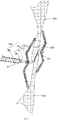
- the present disclosure provides an occluding system 100 including an occluder 20 and a delivery device 50 for releasing the occluder 20.
- the occluder 20 is used for occluding a defect in a vasculature, and the defect includes, but is not limited to an oval foramen, ductus arteriosus, an atrial septal defect and a ventricular septal defect.
- the oval foramen 200 will be taken as the example of the defect, to illustrate the advantages of the occluding system 100 for treating the PFOs. It may be understood that the defect may also be other defects as mentioned above.
- the occluder 20 includes two occluding disks and a tightening element.
- the two occluding disks are used for covering different openings of the oval foramen 200, which are the two openings of the oval foramen 200 respectively located in the left atrium and the right atrium.
- the tightening element includes a tightening thread 21, and is formed by twisting and knotting the tightening thread 21.
- the tightening thread 21 passes through the oval foramen 200 and is connected to the two occluding disks.
- the length of the tightening thread 21 located between the two occluding disks is adjustable by means of a free end of the tightening thread 21.
- the two occluding disks respectively cover the peripheries of the two opposite side openings of the oval foramen 200, that is, regions on two side surfaces of both of a septum primum 301 and a septum secundum 303 adjacent to the oval foramen 200 are covered by the two occluding disks.
- the distance of the two occluding disks is controlled so as to adapt to an anatomical structure of a patient, which improves the attachment of the two occluding disks to the oval foramen 200, and thus, the oval foramen 200 is stably occluded.
- the occluder 20 After the occluder 20 is implanted, it is ensured that the degree of the deformation of two septa (the septum primum 301 and the septum secundum 303) is smaller, the endothelialization of the two septa to the occluding disks is not affected, residual diffluence is reduced, the trouble of requirement to customize the occluder for a particular patient due to a specific structure of the oval foramen 200 is avoided, and the application of the PFO occluder is effectively widened, so that more patients get benefits from minimally invasive surgeries.
- the degree of the deformation of two septa the septum primum 301 and the septum secundum 303
- the occluder 20 is further used for occluding a plurality of openings in the defect from two sides.
- the two occluding disks are respectively a first occluding disk 201 and a second occluding disk 205.
- the tightening thread 21 includes a knot 22, a connecting section 23 connected with the knot 22, as well as a locking section 24 and an adjusting section 25 which are connected with the knot 22.
- the connecting section 23 is connected between the first occluding disk 201 and the second occluding disk 205.
- the connecting section 23 is connected to the geometric center of the first occluding disk 201, and/or the connecting section 23 is connected to the geometric center of the second occluding disk 205.
- the locking section 24 includes a free end 241.
- the adjusting section 25 includes a free end 251. All of the locking section 24, the adjusting section 25 and the knot 22 are disposed on one side of the second occluding disk 205 away from the first occluding disk 201.
- the length of the connecting section 23 can be adjusted by means of the adjusting section 25.
- the free end 241 of the locking section 24 and the free end 251 of the adjusting section 25 are connected to the delivery device 50.
- the delivery device 50 is controllable to pull the free end 251 so as to adjust the length of the connecting section 23 between the first occluding disk 201 and the second occluding disk 205, thereby adjusting the distance between the two occluding disks.
- the delivery device 50 is controllable to pull the free end 241 to lock the adjusting section 25 by the knot 22, so that the distance between the first occluding disk 201 and the second occluding disk 205 is fixed relative to each other, to thereby fix the distance between the first occluding disk 201 and the second occluding disk 205, which is advantageous to maintain the relative positions of the septum primum 301, the septum secundum 303 and the two occluding disks and attachment there during and after the operation, and thus, the difficulty in withdrawing the delivery device 50 is reduced, and it facilitates to growth of the two septa towards the occluder 20 to complete endothelialization and form a permanent atrial septa after operation.
- both of the adjusting section 25 and the locking section 24 are movable threads connected to the occluding disks, operating the adjusting section 25 or the locking section 24 independently may cause the occluding disks to move, and thus, unsatisfied operability may be caused. Therefore, the tightening element further includes a fixing thread 26 connected with the delivery device 50. One of the two occluding disks is fixed, by means of the fixing thread 26, to a distal end of the delivery device 50.
- the second occluding disk 205 is connected with the fixing thread 26, and the fixing thread 26 is used for fixing the second occluding disk 205 to the distal end of the delivery device 50 to prevent both of the two occluding disks from shaking when the adjusting section 25 or the locking section 24 is pulled, thereby facilitating to adjust the length of the connecting section 23 and lock the adjusting section 25 by the knot 22.
- one end of the fixing thread 26 is connected to a central portion of the second occluding disk 205, and the other end of the fixing thread 26 is fixed to the delivery device 50.
- the first occluding disk 201 is delivered to the left atrium by the delivery device 50 and is unfolded in the left atrium
- the second occluding disk 205 is delivered to the right atrium by the delivery device 50 and is unfolded in the right atrium.
- the connecting section 23 connected between the first occluding disk 201 and the second occluding disk 205 is flexible and is adjustable in length.
- the connecting section 23 passes through the oval foramen 200 between the septum primum 301 and the septum secundum 303.
- the adjusting section 25 is pulled towards the proximal end to shorten the connecting section 23 gradually, that is, the distance between the first occluding disk 201 and the second occluding disk 205 is gradually reduced.
- the septum primum 301 and the septum secundum 303 approach each other and are clamped by the first occluding disk 201 and the second occluding disk 205.
- the first occluding disk 201 covers the septum primum 301 and the septum secundum 303 at areas around the oval foramen 200
- the second occluding disk 205 covers the septum primum 301 and the septum secundum 303 at areas around the oval foramen 200, that is, the two side openings of the oval foramen 200 in the left atrium and the right atrium are respectively covered by the first occluding disk 201 and the second occluding disk 205.
- each of the first occluding disk 201 and the second occluding disk 205 includes a supporting frame and a flow blocking membrane disposed on the supporting frame.
- the flow blocking membranes on two sides of the oval foramen 200 can block blood to flow into the oval foramen 200, thereby preventing a blood flow from flowing from the left atrium to the right atrium and thus achieving occlusion immediately.
- the septum primum 301 and the septum secundum 303 creep to positions where they are in contact with the first occluding disk 201 and the second occluding disk 205, respectively, so that the oval foramen 200 is closed after endothelialization is completed, and then, an integrated atrial septum can be formed.
- structures of the supporting frames on the two occluding disks are dense enough, as such the flow blocking membranes can be omitted, which will not affect the endothelialization of the two septa to the occluding disks, and no diffluence or little diffluence will be formed on a passageway of the oval foramen, for example, the diffluence is less than a preset proportion which may be 10%, 5%, 3%, etc.
- the faces of the first occluding disk 201 and the second occluding disk 205 may be configured to be circular, oval, triangular or of other shapes which are irregular.
- the radial area of the first occluding disk 201 may be the same as or different from the radial area of the second occluding disk 205.
- both of the first occluding disk 201 and the second occluding disk 205 are substantially disk-shaped, and the radial area of the first occluding disk 201 is smaller than the radial area of the second occluding disk 205.
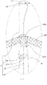
- the first occluding disk 201 includes a first supporting frame 2011 and a first flow blocking membrane 2013 disposed on the first supporting frame 2011.
- the first flow blocking membrane 2013 may be fixedly attached to the inner surface and/or outer surface of the first supporting frame 2011.
- the first flow blocking membrane 2013 may alternatively be fixedly disposed in an inner cavity of the first supporting frame 2011, and the first flow blocking membrane 2013 at least covers a radial region of the first supporting frame 2011.
- the tightening thread 21 is connected with the first supporting frame 2011 and/or the first flow blocking membrane 2013.
- the connecting section 23 of the tightening thread 21 slidably passes through the first supporting frame 2011.
- the second occluding disk 205 includes a second supporting frame 2051 and a second flow blocking membrane 2053 disposed on the second supporting frame 2051.
- the second flow blocking membrane 2053 may be fixedly attached to the inner surface and/or outer surface of the second supporting frame 2051.
- the second flow blocking membrane 2053 may alternatively be fixedly disposed in an inner cavity of the second supporting frame 2051, and the second flow blocking membrane 2053 at least covers a radial region of the second supporting frame 2051.
- One end of the adjusting section 25 passes through the second flow blocking membrane 2053 from a gap in the second supporting frame 2051, so as to be connected with the knot 22.
- the first flow blocking membrane 2013 and the second flow blocking membrane 2053 may be membranes made of non-degradable polymer materials having good biocompatibility, such as ePTFE or PET materials.
- the first flow blocking membrane 2013 and the second flow blocking membrane 2053 may alternatively be made of absorbable polymer materials such as polylactic acid, polycaprolactone, polylactic acid-polycaprolactone copolymer and the like.
- the first flow blocking membrane 2013 and the second flow blocking membrane 2053 are fixed to the inner or outer surfaces of the occluding disks by means of suturing or adhering to occlude the blood flow.
- the outer surface of the first occluding disk 201 is fixedly attached with the first flow blocking membrane 2013.
- the outer surface of the second occluding disk 205 is fixedly attached with the second flow blocking membrane 2053.
- the first supporting frame 2011 and the second supporting frame 2051 are woven meshed structures or frame structures, so that the first occluding disk 201 and the second occluding disk 205 may be sufficiently attached to the surface of the atrial septum.
- Each of the first supporting frame 2011 and the second supporting frame 2051 may be anyone of the following: a single-layer woven meshed structure, a single-layer frame structure, a double-layer meshed structure and a double-layer frame structure.
- both of the first supporting frame 2011 and the second supporting frame 2051 are single-layer woven meshed structure.
- the woven meshed structures or frame structures may have a petal-like shape, that is, the first supporting frame 2011 and the second supporting frame 2051 are of the petal-shaped structures.
- the petal-shaped structure consists of a plurality of supporting wire units, which are arranged in an annular array around a center of the woven meshed structure or frame structure. Each of the supporting wire units passes through the center.
- the first supporting frame 2011 and the second supporting frame 2051 may be made of various biocompatible materials, that is, each of the supporting wire units may be made of various biocompatible materials, and the various biocompatible materials include materials commonly used in the manufacture of a releasable medical instrument, such as memory alloy materials, preferably, nickel-titanium alloy.
- the first supporting frame 2011 and the second supporting frame 2051 may alternatively be made of degradable materials, that is, each of the supporting wire units is made of the degradable material, and the degradable materials include polylactic acid (PLA), polycaprolactone (PCL), polyglycollide (PGA), and polydioxanone (PDO) and the like.
- the supporting frames may be made of macromolecular polymer materials, etc.
- the peripheral edge of the first supporting frame 2011 is inclinedly bent towards the second supporting frame 2051, and the peripheral edge of the second supporting frame 2051 is inclinedly bent towards the first supporting frame 2011.
- the portion of each supporting wire unit of the first supporting frame 2011 away from the geometric center of the first supporting frame 2011 is inclinedly bent towards the second supporting frame 2051.
- the portion of each supporting wire unit of the second supporting frame 2051 away from the geometric center of the second supporting frame 2051 is inclinedly bent towards the first supporting frame 2011.
- the distance between the central portions of the first occluding disk 201 and the middle of the second occluding disk 205 is greater than the distance between the peripheral edges thereof, so that the septum primum 301 and the septum secundum 303 surrounding the oval foramen may be more firmly clamped by the first occluding disk 201 and the second occluding disk 205.
- the first occluding disk 201 further includes a first rigid sleeve 2015 disposed in a central region thereof.
- the first rigid sleeve 2015 is disposed in the geometric center of the first occluding disk 201.
- the supporting wire units 2012 of the first occluding disk 201 are connected with the first rigid sleeve 2015 and are disposed around the first rigid sleeve 2015 to form the first supporting frame 2011.
- the first rigid sleeve 2015 is tubular and is provided with a through hole extending in a thickness direction (a direction perpendicular to the surface of the first occluding disk 201) of the first occluding disk 2011.
- Free ends of the supporting wire units 2012 are fixedly disposed on the outer or inner circumferential surface of the first rigid sleeve 2015.
- the free ends of the supporting wire units 2012 are accommodated in an inner cavity of the first rigid sleeve 2015 and are fixedly connected to the first rigid sleeve 2015 by welding or bonding.
- the first rigid sleeve 2015 is made of stainless steel, nickel-titanium alloy or other biocompatible materials.
- the second occluding disk 205 further includes a second rigid sleeve 2055 disposed in a central region thereof.
- the second rigid sleeve 2055 is connected with the second supporting frame 2051.
- the second rigid sleeve 2055 is fixedly disposed in the geometric center of the second occluding disk 205.
- the supporting wire units of the second occluding disk 205 are disposed around the second rigid sleeve 2055 to form the second supporting frame 2051.
- the second rigid sleeve 2055 is tubular and is provided with a through threading hole 2056 in a thickness direction of the second supporting frame 2051. One end of the connecting section 23 passes through the threading hole 2056 so as to be connected with the knot 22.
- Free ends of the supporting wire units are fixedly disposed on the outer or inner peripheral surface of the second rigid sleeve 2055.
- the free ends of the several supporting wire units are fixedly connected to the outer peripheral surface of the second rigid sleeve 2055 by welding or bonding.
- the second rigid sleeve 2055 is made of stainless steel, nickel-titanium alloy or other biocompatible materials.
- first rigid sleeve 2015 may also be disposed in a region of the first occluding disk 201 other than the central region thereof.
- the second rigid sleeve 2055 may also be disposed in a region of the second occluding disk 205 other than the central region thereof.
- the first supporting frame 2011 and the second supporting frame 2051 are generally woven by using 4 to 50 supporting wire units, with mesh openings defined between the adjacent supporting wire units.
- the first supporting frame 2011 will be taken as example for illustration, and the following technical solution is also suitable for the second supporting frame 2051.
- the first supporting frame 2011 shown in FIG. 4 is formed by thirty circular supporting wire units 2012 annularly arranged in array.
- the first supporting frame 2011 shown in FIG. 5 and FIG. 6 is formed by six circular supporting wire units 2012 annularly arranged in array.
- the first supporting frame 2011 shown in FIG. 6 is provided with a first flow blocking membrane 2013.
- each of the supporting wire units may be oval, semicircular, rhombic or irregular shapes.
- a first supporting frame 2011a is formed by a plurality of oval supporting wire units 2012 annularly arranged in array around a central point of the first supporting frame 2011a. One vertex of each supporting wire unit 2012 passes through the central point.
- the inner surface and/or the outer surface of the first supporting frame 2011a is provided with the flow blocking membrane.
- a first supporting frame 2011b is formed by a plurality of semicircular supporting wire units 2012 annularly arranged in array around a central point of the first supporting frame 2011b. One end of the arc of each supporting wire unit 2012 passes through the central point.
- a first supporting frame 2011c is formed by a plurality of rhombic supporting wire units 2012 annularly arranged in array around a central point of the first supporting frame 2011c. One vertex of each supporting wire unit 2012 passes through the central point.
- the inner surface and/or the outer surface of the first supporting frame 2011c is provided with the flow blocking membrane.
- a first supporting frame 2011d is formed by a plurality of supporting wire units 2012 of the irregular shapes annularly arranged in array around a central point of the first supporting frame 2011d, a top end of each supporting wire units 2012 passes through the central point.
- the inner surface and/or the outer surface of the first supporting frame 2011d is provided with the flow blocking membrane.
- each of the supporting wire units may be triangular, polygonal, etc.
- the tightening thread 21 may be a non-absorbable biocompatible suture such as a metal thread, a cotton thread, a polyester thread, a polypropylene thread, etc.
- the tightening thread 21 may also be an absorbable biocompatible suture such as a catgut, a polyglycollide thread, a multi-silk non-biodegradable suture, etc.
- the tightening thread 21 may also be a forcedly-wound fiber thread, etc.
- the connecting section 23 is an inverted U-shaped adjusting thread loop 230 defined by the tightening thread 21.
- Two ends of the adjusting thread loop 230 pass through the second occluding disk 205 and are connected with the knot 22.
- the part of the adjusting thread loop 230 away from the knot 22 slidably passes through the first occluding disk 201.
- the part of the adjusting thread loop 230 away from the knot 22 and the adjusting section 25 slidably passes through the geometric center of the first occluding disk 201.
- Two ends of the adjusting thread loop 230 respectively pass through the geometric center of the second occluding disk 205 in the thickness direction of the second occluding disk 205, so that forces applied on the first occluding disk 201 and the second occluding disk 205 are more uniform.
- Positions of the first occluding disk 201 and the second occluding disk 205 through which two ends of the adjusting thread loop 230 pass are located in the geometric centers of the first occluding disk 201 and the second occluding disk 205. As such, it facilitates to apply a pulling force to the geometric centers of the occluding disks when the tightening thread 21 is tightened, so that the force applied on the occluding disks is uniform, and it is convenient to operate.
- the first occluding disk 201 is connected with the connecting section 23 at a plurality of positions that are close to each other, and/or the second occluding disk 205 is connected with the connecting section 23 at a plurality of positions that are close to each other.
- positions of two mesh openings of the first occluding disk 201 through which the connecting section 23 passes are close to each other.
- one end of the connecting section 23 passes through the threading hole 2056 of the second rigid sleeve 2055, and the other end of the connecting section 23 passes through a mesh opening which is close to the threading hole 2056.
- the positions of the through holes of the connecting section 23 on the two disks are gathered, avoiding the through holes in the flow blocking membranes from becoming larger and larger due to pulling by the connecting section 23, which facilitates to maintain the integrity of the flow blocking membranes for a long term, and it is ensured that the defected septum primum 301 and the septum secundum 303 creep towards the surface of the occluder to complete endothelialization after the operation.
- One end of the adjusting thread loop 230 is connected to the knot 22, and the other end of the adjusting thread loop 230 passes through the knot 22 and is connected with the adjusting section 25.
- the adjusting section 25 is capable of driving the end of the adjusting thread loop 230 connected thereto to slide in the knot 22, to thereby adjust the length of the adjusting thread loop 230 between the first occluding disk 201 and the second occluding disk 205.
- the locking section 24 is used for tightening the knot 22 to make the knot 22 tighten a part of the adjusting thread loop 230 located in the knot 22, to thereby fix the length of the adjusting thread loop 230 between the first occluding disk 201 and the second occluding disk 205.
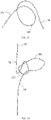
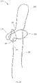
- the knot 22 includes a base thread loop 221 and a locking thread loop 223 which are interconnected.
- One end of the adjusting thread loop 230 is connected with the base thread loop 221, and the other end of the adjusting thread loop 230 passes through the locking thread loop 223 and is connected with the adjusting section 25.
- the adjusting section 25 is capable of driving the end of the adjusting thread loop 230 connected thereto to slide in the locking thread loop 223, so as to adjust the length of the adjusting thread loop 230 between the first occluding disk 201 and the second occluding disk 205.
- the locking section 24 is tightened, the locking thread loop 223 and the base thread loop 221 are sequentially and gradually tightened, so that one part of the adjusting thread loop 230 is tightened and locked in the locking thread loop 223.
- the tightening thread 21 includes a first section 211 (as shown in FIG. 11 ) connected with the locking section 24 and a second section 213 (as shown in FIG. 11 ) connected with the adjusting section 25.
- the first section 211 and the second section 213 are interconnected.
- the base thread loop 221 is defined by the first section 211, and the locking thread loop 223 is formed by a remaining part of the first section 211 passing through the base thread loop 221.
- the adjusting thread loop 230 is defined by the second section 213.
- the sides located between the first occluding disk 201 and the second occluding disk 205 are inner sides
- the side of the first occluding disk 201 away from the second occluding disk 205 is an outer side
- the side of the second occluding disk 205 away from the first occluding disk 201 is an outer side
- Two ends of the adjusting thread loop 230 pass through the second occluding disk 205 from the inner side of the second occluding disk 205 to the outer side of the second occluding disk 205, and the end of the adjusting thread loop 230 away from the knot 22 passes through the inner side of the first occluding disk 201.
- the occluding system 100 may be used in combination with a guide wire, a delivery device 50, a dilator, etc.
- a surgical process is described as follows.
- an occluder provided in a second embodiment of the present disclosure has a structure after release similar to that of the first embodiment, except that a knot 22a of a tightening thread 21a of the occluder in the second embodiment has a structure slightly different from the structure of the knot 22 in the first embodiment.
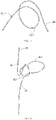
- the knot 22a is additionally provided with a reinforcing thread loop 226 on the basis of the knot 22 in the first embodiment.
- One end of the reinforcing thread loop 226 is connected to the base thread loop 221, and the other end of the reinforcing thread loop 226 passes through a gap between the base thread loop 221 and the locking thread loop 223 to connect with the adjusting thread loop 230.
- a knotting method of the knot 22a is similar to the knotting method of the knot 22, which is specifically described as follows.
- the base thread loop 221 and the locking thread loop 223 of the tightening element 21a partially overlap, and the first direction and the second direction may be defined as one of the two situations described as follows.
- a method for assembling the tightening thread 21 with the first occluding disk 201 and the second occluding disk 205 in the second embodiment is similar to that in the first embodiment, that is, before the knot 22a is knotted, directing one end of the tightening thread 21 passesto pass through the mesh openings of the first occluding disk 201 first, then to return to the inner side of the first occluding disk 201 adjacent to the other end of the tightening thread 21a, so that the tightening thread 21a is located on the inner side of the first occluding disk 201; then, directing one end of the tightening thread 21a passes to pass through the threading hole 2056 of the second rigid sleeve 2055 from the inner side to the outer side of the second occluding disk 205, and directing the other end of the tightening thread 21a passesto pass through a mesh opening adjacent to the second rigid sleeve 2055 from the inner side to the outer side of the
- a using process of an occluding system of the second embodiment is the same as the using process of the occluding system of the first embodiment, which will not be described again.
- the locking section 24 and the adjusting section 25 may also be inserted into and wound around the adjusting thread loop 230 and the locking ring thread 223 several more times, provided that length adjustment and locking functions are not impeded.
- the knot 22 may be further knotted in other manners, as long as the knot 22 is coupled with the first occluding disk 201 or the second occluding disk 205, which can adjust the length of the connecting section 23 and can be locked.
- the first rigid sleeve 2015 and the second rigid sleeve 2055 are omitted in the first occluding disk 201 and the second occluding disk 205, and the tightening thread 21 passes through the mesh openings of the first occluding disk 201 and the second occluding disk 205 so as to be connected with the first occluding disk 201 and the second occluding disk 205.
- each of the first occluding disk 201 and the second occluding disk 205 may be a single-layer meshed disk or a double-layer meshed disk.
- a gasket is additionally provided on the basis of the first embodiment. Specifically, the gasket is disposed on the geometric center of the outer side of the second occluding disk 205.
- the gasket is provided with through holes extending in the thickness direction of the second occluding disk 205 which are spaced apart. As shown in FIG. 2 , one of the through holes corresponds to the threading hole 2056 of the second rigid sleeve 2055 for one end of the adjusting thread loop 230 passing through.
- the other through hole corresponds to the other end of the adjusting thread loop 23 for the other end of the adjusting thread loop 23 passing through.
- All of the knot 22, the locking section 24 and the adjusting section 25 are located on the side of the gasket away from the second occluding disk 205.
- force applied on the outer side of the second occluding disk 205 is more uniform, so that a clamping force between the first occluding disk 201 and the second occluding disk 205 is more uniform to achieve more stable occlusion.
Landscapes
- Health & Medical Sciences (AREA)
- Surgery (AREA)
- Life Sciences & Earth Sciences (AREA)
- Medical Informatics (AREA)
- Animal Behavior & Ethology (AREA)
- Engineering & Computer Science (AREA)
- Biomedical Technology (AREA)
- Heart & Thoracic Surgery (AREA)
- Veterinary Medicine (AREA)
- Molecular Biology (AREA)
- Nuclear Medicine, Radiotherapy & Molecular Imaging (AREA)
- General Health & Medical Sciences (AREA)
- Public Health (AREA)
- Reproductive Health (AREA)
- Vascular Medicine (AREA)
- Cardiology (AREA)
- Surgical Instruments (AREA)
Applications Claiming Priority (3)
| Application Number | Priority Date | Filing Date | Title |
|---|---|---|---|
| CN201922292918.9U CN212165820U (zh) | 2019-12-18 | 2019-12-18 | 封堵器及封堵系统 |
| CN201911313841.7A CN112998769A (zh) | 2019-12-18 | 2019-12-18 | 封堵器、封堵系统及封堵器中收紧件的打结方法 |
| PCT/CN2020/137639 WO2021121395A1 (zh) | 2019-12-18 | 2020-12-18 | 封堵器、封堵系统及封堵器中收紧件的打结方法 |
Publications (2)
| Publication Number | Publication Date |
|---|---|
| EP4079232A1 true EP4079232A1 (de) | 2022-10-26 |
| EP4079232A4 EP4079232A4 (de) | 2023-12-27 |
Family
ID=76477100
Family Applications (1)
| Application Number | Title | Priority Date | Filing Date |
|---|---|---|---|
| EP20904197.9A Withdrawn EP4079232A4 (de) | 2019-12-18 | 2020-12-18 | Verschluss, verschlusssystem und knotenverfahren zum festziehen des elementes im verschluss |
Country Status (3)
| Country | Link |
|---|---|
| US (1) | US20220346803A1 (de) |
| EP (1) | EP4079232A4 (de) |
| WO (1) | WO2021121395A1 (de) |
Families Citing this family (8)
| Publication number | Priority date | Publication date | Assignee | Title |
|---|---|---|---|---|
| CN114641242B (zh) | 2019-09-26 | 2025-11-18 | 苏黎世大学 | 左心耳闭塞装置 |
| CN121400898A (zh) * | 2020-02-03 | 2026-01-27 | 圣犹达医疗用品心脏病学部门有限公司 | 带有介入通道的封堵器的框架和补片设计 |
| WO2022002086A1 (zh) * | 2020-07-01 | 2022-01-06 | 杭州德诺电生理医疗科技有限公司 | 封堵器及封堵系统 |
| CN115813458A (zh) * | 2021-09-16 | 2023-03-21 | 杭州德诺电生理医疗科技有限公司 | 封堵器以及封堵器的制备方法 |
| CN116407173A (zh) * | 2021-12-31 | 2023-07-11 | 杭州德晋医疗科技有限公司 | 可调节封堵装置以及封堵系统 |
| CN114795309B (zh) * | 2022-04-01 | 2025-04-11 | 上海形状记忆合金材料有限公司 | 一种封堵器 |
| WO2025217962A1 (zh) * | 2024-04-15 | 2025-10-23 | 邢泉生 | 双盘状一体成型可降解心脏房间隔卵圆孔封堵器 |
| CN119074103B (zh) * | 2024-08-15 | 2026-01-02 | 上海形状记忆合金材料有限公司 | 一种心血管介入封堵器输送系统 |
Family Cites Families (28)
| Publication number | Priority date | Publication date | Assignee | Title |
|---|---|---|---|---|
| US4917089A (en) * | 1988-08-29 | 1990-04-17 | Sideris Eleftherios B | Buttoned device for the transvenous occlusion of intracardiac defects |
| US5284488A (en) * | 1992-12-23 | 1994-02-08 | Sideris Eleftherios B | Adjustable devices for the occlusion of cardiac defects |
| US5433727A (en) * | 1994-08-16 | 1995-07-18 | Sideris; Eleftherios B. | Centering buttoned device for the occlusion of large defects for occluding |
| US6695867B2 (en) * | 2002-02-21 | 2004-02-24 | Integrated Vascular Systems, Inc. | Plunger apparatus and methods for delivering a closure device |
| US7338514B2 (en) * | 2001-06-01 | 2008-03-04 | St. Jude Medical, Cardiology Division, Inc. | Closure devices, related delivery methods and tools, and related methods of use |
| US8021359B2 (en) * | 2003-02-13 | 2011-09-20 | Coaptus Medical Corporation | Transseptal closure of a patent foramen ovale and other cardiac defects |
| ES2293357T3 (es) * | 2003-10-24 | 2008-03-16 | Ev3 Endovascular, Inc. | Sistema de cierre de un foramen oval permeable. |
| US8262694B2 (en) * | 2004-01-30 | 2012-09-11 | W.L. Gore & Associates, Inc. | Devices, systems, and methods for closure of cardiac openings |
| JP4366306B2 (ja) * | 2004-12-17 | 2009-11-18 | テルモ株式会社 | 生体内組織閉鎖具および生体内組織閉鎖装置 |
| EP2135560B1 (de) * | 2005-06-02 | 2011-08-10 | Cordis Corporation | Medizinische Vorrichtung zum Einsatz einer mechanischen Verschlusseinrichtung |
| CN101257852B (zh) * | 2005-07-07 | 2011-08-10 | 科迪斯公司 | 具有可控传送系统的未闭卵圆孔闭合设备 |
| CA2621197A1 (en) * | 2005-09-01 | 2007-03-08 | Cordis Corporation | Patent foramen ovale closure method |
| US20070225755A1 (en) * | 2006-03-22 | 2007-09-27 | Radi Medical Systems Ab | Closure device |
| US8551135B2 (en) * | 2006-03-31 | 2013-10-08 | W.L. Gore & Associates, Inc. | Screw catch mechanism for PFO occluder and method of use |
| US8870913B2 (en) * | 2006-03-31 | 2014-10-28 | W.L. Gore & Associates, Inc. | Catch system with locking cap for patent foramen ovale (PFO) occluder |
| WO2008010738A2 (en) * | 2007-01-24 | 2008-01-24 | Uros Babic | Patent foramen ovale occluder with suture based anchor |
| US8322341B2 (en) * | 2008-09-09 | 2012-12-04 | Conceptus, Inc. | System and method for occluding a reproductive body lumen |
| US20110054492A1 (en) * | 2009-08-26 | 2011-03-03 | Abbott Laboratories | Medical device for repairing a fistula |
| CN201831930U (zh) * | 2010-09-06 | 2011-05-18 | 上海交通大学医学院附属上海儿童医学中心 | 一种防嵌顿一次性包皮套扎器 |
| CN103654883B (zh) * | 2013-12-06 | 2017-01-04 | 深圳市先健生物材料技术有限公司 | 带锁定机构的封堵器 |
| CN106413589A (zh) * | 2014-06-11 | 2017-02-15 | 奥特鲁泰克控股有限公司 | 左心耳封堵器 |
| WO2017001998A1 (en) * | 2015-06-30 | 2017-01-05 | De Rezende Neto João Baptista | Cardiac injury device |
| CN206777370U (zh) * | 2016-09-22 | 2017-12-22 | 杭州诺茂医疗科技有限公司 | 一种可调距离的左心耳封堵器 |
| CN207837587U (zh) * | 2017-04-11 | 2018-09-11 | 上海形状记忆合金材料有限公司 | 一种隧道状卵圆孔未闭封堵器械 |
| CN108451570A (zh) * | 2018-02-23 | 2018-08-28 | 上海形状记忆合金材料有限公司 | 辅助完全可降解封堵器体内成型的装置及方法 |
| US12544076B2 (en) * | 2018-05-29 | 2026-02-10 | Amx Technologies, Llc | Method and system for closure of cardiovascular apertures |
| CN209770426U (zh) * | 2018-11-30 | 2019-12-13 | 广州启骏生物科技有限公司 | 卵圆孔未闭封堵器与卵圆孔未闭封堵系统 |
| WO2020210818A1 (en) * | 2019-04-12 | 2020-10-15 | The Trustees Of Columbia University In The City Of New York | Transcatheter closure of patent foramen ovale with bipolar rf application |
-
2020
- 2020-12-18 EP EP20904197.9A patent/EP4079232A4/de not_active Withdrawn
- 2020-12-18 WO PCT/CN2020/137639 patent/WO2021121395A1/zh not_active Ceased
-
2022
- 2022-06-17 US US17/843,648 patent/US20220346803A1/en active Pending
Also Published As
| Publication number | Publication date |
|---|---|
| WO2021121395A1 (zh) | 2021-06-24 |
| EP4079232A4 (de) | 2023-12-27 |
| US20220346803A1 (en) | 2022-11-03 |
Similar Documents
| Publication | Publication Date | Title |
|---|---|---|
| US20220346803A1 (en) | Occluder, occluding system, and knotting method for tightening element in occluder | |
| JP3712630B2 (ja) | 中隔欠損閉鎖装置 | |
| US8366741B2 (en) | Occlusion device with centering arm | |
| AU2016201859B2 (en) | Heart occlusion devices | |
| AU2009341808B2 (en) | Heart occlusion devices | |
| EP2043527B1 (de) | Intraluminale einzelscheibenverschlussvorrichtung für offenes foramen ovale | |
| CA2844300C (en) | Heart occlusion devices | |
| US8992545B2 (en) | Implant-catheter attachment mechanism using snare and method of use | |
| JP4990775B2 (ja) | 閉鎖装置、閉鎖装置の供給方法、および閉鎖装置の使用方法 | |
| US7582104B2 (en) | Daisy design for occlusion device | |
| CN110720958B (zh) | 封堵器及封堵系统 | |
| CN212996550U (zh) | 封堵器及封堵系统 | |
| US20070118176A1 (en) | Radiopaque bioabsorbable occluder | |
| CA2488337A1 (en) | Patent foramen ovale (pfo) closure device with radial and circumferential support | |
| EP1620017A2 (de) | Verschlussvorrichtungen, darauf bezogenes einbringungsverfahren und werkzeuge und darauf bezogene methoden des gebrauches | |
| WO2005006990A2 (en) | Tubular patent foramen ovale (pfo) closure device with catch system | |
| CN112998769A (zh) | 封堵器、封堵系统及封堵器中收紧件的打结方法 | |
| CN212165820U (zh) | 封堵器及封堵系统 | |
| CN113876370A (zh) | 封堵器及封堵系统 | |
| WO2023160665A1 (zh) | 一种封堵器 | |
| US12527560B2 (en) | Occluder and occlusion system | |
| WO2022002087A1 (zh) | 封堵器及封堵系统 | |
| US20250221695A1 (en) | Occluder | |
| CN116509468A (zh) | 封堵系统及收紧件的打结方法 |
Legal Events
| Date | Code | Title | Description |
|---|---|---|---|
| STAA | Information on the status of an ep patent application or granted ep patent |
Free format text: STATUS: THE INTERNATIONAL PUBLICATION HAS BEEN MADE |
|
| PUAI | Public reference made under article 153(3) epc to a published international application that has entered the european phase |
Free format text: ORIGINAL CODE: 0009012 |
|
| STAA | Information on the status of an ep patent application or granted ep patent |
Free format text: STATUS: REQUEST FOR EXAMINATION WAS MADE |
|
| 17P | Request for examination filed |
Effective date: 20220718 |
|
| AK | Designated contracting states |
Kind code of ref document: A1 Designated state(s): AL AT BE BG CH CY CZ DE DK EE ES FI FR GB GR HR HU IE IS IT LI LT LU LV MC MK MT NL NO PL PT RO RS SE SI SK SM TR |
|
| DAV | Request for validation of the european patent (deleted) | ||
| DAX | Request for extension of the european patent (deleted) | ||
| A4 | Supplementary search report drawn up and despatched |
Effective date: 20231123 |
|
| RIC1 | Information provided on ipc code assigned before grant |
Ipc: A61B 17/04 20060101ALI20231117BHEP Ipc: A61B 17/00 20060101AFI20231117BHEP |
|
| STAA | Information on the status of an ep patent application or granted ep patent |
Free format text: STATUS: THE APPLICATION IS DEEMED TO BE WITHDRAWN |
|
| 18D | Application deemed to be withdrawn |
Effective date: 20240613 |