EP4078733B1 - Buchsenkontakt - Google Patents
Buchsenkontakt Download PDFInfo
- Publication number
- EP4078733B1 EP4078733B1 EP20838341.4A EP20838341A EP4078733B1 EP 4078733 B1 EP4078733 B1 EP 4078733B1 EP 20838341 A EP20838341 A EP 20838341A EP 4078733 B1 EP4078733 B1 EP 4078733B1
- Authority
- EP
- European Patent Office
- Prior art keywords
- contact
- socket
- region
- socket contact
- pin
- Prior art date
- Legal status (The legal status is an assumption and is not a legal conclusion. Google has not performed a legal analysis and makes no representation as to the accuracy of the status listed.)
- Active
Links
Images
Classifications
-
- H—ELECTRICITY
- H01—ELECTRIC ELEMENTS
- H01R—ELECTRICALLY-CONDUCTIVE CONNECTIONS; STRUCTURAL ASSOCIATIONS OF A PLURALITY OF MUTUALLY-INSULATED ELECTRICAL CONNECTING ELEMENTS; COUPLING DEVICES; CURRENT COLLECTORS
- H01R13/00—Details of coupling devices of the kinds covered by groups H01R12/70 or H01R24/00 - H01R33/00
- H01R13/02—Contact members
- H01R13/10—Sockets for co-operation with pins or blades
- H01R13/11—Resilient sockets
- H01R13/111—Resilient sockets co-operating with pins having a circular transverse section
-
- H—ELECTRICITY
- H01—ELECTRIC ELEMENTS
- H01R—ELECTRICALLY-CONDUCTIVE CONNECTIONS; STRUCTURAL ASSOCIATIONS OF A PLURALITY OF MUTUALLY-INSULATED ELECTRICAL CONNECTING ELEMENTS; COUPLING DEVICES; CURRENT COLLECTORS
- H01R13/00—Details of coupling devices of the kinds covered by groups H01R12/70 or H01R24/00 - H01R33/00
- H01R13/02—Contact members
- H01R13/10—Sockets for co-operation with pins or blades
- H01R13/11—Resilient sockets
-
- H—ELECTRICITY
- H01—ELECTRIC ELEMENTS
- H01R—ELECTRICALLY-CONDUCTIVE CONNECTIONS; STRUCTURAL ASSOCIATIONS OF A PLURALITY OF MUTUALLY-INSULATED ELECTRICAL CONNECTING ELEMENTS; COUPLING DEVICES; CURRENT COLLECTORS
- H01R4/00—Electrically-conductive connections between two or more conductive members in direct contact, i.e. touching one another; Means for effecting or maintaining such contact; Electrically-conductive connections having two or more spaced connecting locations for conductors and using contact members penetrating insulation
- H01R4/10—Electrically-conductive connections between two or more conductive members in direct contact, i.e. touching one another; Means for effecting or maintaining such contact; Electrically-conductive connections having two or more spaced connecting locations for conductors and using contact members penetrating insulation effected solely by twisting, wrapping, bending, crimping, or other permanent deformation
- H01R4/18—Electrically-conductive connections between two or more conductive members in direct contact, i.e. touching one another; Means for effecting or maintaining such contact; Electrically-conductive connections having two or more spaced connecting locations for conductors and using contact members penetrating insulation effected solely by twisting, wrapping, bending, crimping, or other permanent deformation by crimping
- H01R4/183—Electrically-conductive connections between two or more conductive members in direct contact, i.e. touching one another; Means for effecting or maintaining such contact; Electrically-conductive connections having two or more spaced connecting locations for conductors and using contact members penetrating insulation effected solely by twisting, wrapping, bending, crimping, or other permanent deformation by crimping for cylindrical elongated bodies, e.g. cables having circular cross-section
Definitions
- the invention is based on a socket contact according to the preamble of independent claim 1.
- Such socket contacts are used in connectors to transmit electrical currents, signals and/or data.
- the DE 1 640 554 A1 shows a socket contact that is made from a flat spring steel sheet using the stamping and bending technique.
- the contact area of the socket contact has a contact tongue that is folded radially inwards several times.
- the US 5 135 417 A shows a socket contact inserted into a jacket sleeve.
- the socket contact is manufactured using a stamping and bending technique and has a circumferential notch approximately in the middle of its contact area, which serves to improve the electrical contact with the contact pin.
- the spring steel sheet used can be processed easily. However, the current-carrying capacity of a socket contact made from it is not always sufficient.
- the US 2 280 027 A shows a socket contact with a hollow cylindrical contact area from which a contact tongue is machined. A hole is made in the contact tongue, into which a tool is inserted to punch the contact tongue on the inside. The contact tongue is bent radially inwards at this punching edge.
- Contact sockets made from solid material offer better electrical properties. If such a socket contact is made from solid material, for example a piece of wire of the appropriate diameter, the contact tongue may become brittle at the base due to the bending process. In addition, such socket contacts exhibit fluctuations in the so-called pull-out forces at which the contact pin is pulled out of the contact socket. This means that the pull-out force is always set to the upper tolerance limit, which leads to high pull-out forces overall.
- German Patent and Trademark Office has searched the following prior art in the priority application for the present application: DE 200 08 846 U1 , DE 20 24 031 A , DE 11 98 891 B , DE 16 40 554 A and WO 2019/ 206 784 A1 .
- the object of the invention is to propose a socket contact that is easy to manufacture.
- the socket contact should also have a reliable electrical contact with a matching pin contact.
- the socket contact according to the invention has a hollow cylindrical connection area.
- the connection area is intended to accommodate a stripped end area of an electrical conductor to be connected.
- the stripped end section is inserted into the hollow cylindrical connection area.
- the connection area is then crimped using a so-called crimping tool, which creates a reliable electrically conductive connection between the conductor and the socket contact. This is also referred to as a crimp connection.
- connection area has a wall thickness of 0.5 mm to 1 mm.
- the socket contact has a hollow cylindrical contact area.
- the contact area has a pin insertion opening for receiving a
- the contact pin is inserted axially into the contact area for electrical contact.
- the contact area has a cylinder wall. At least one contact tongue is machined out of the cylinder wall in a preferably machining step, which is folded radially inwards. The free end of the contact tongue points towards or in the direction of the pin insertion opening.
- the fixed end of the contact tongue has a so-called attachment on the cylinder wall of the contact area.
- the contact tongue is folded radially inwards at the attachment.
- a groove is made in the cylinder wall that runs at least partially around it. It has been proven that this groove can prevent the contact tongue from becoming brittle in particular at the attachment area. By making this groove, the contact tongue bends much more evenly. This means that the pull-off forces, i.e. when a contact pin is pulled out of the contact socket, are much more even across a large number of similar contact sockets. This increases product quality.
- the invention consists in particular in specifying a fixed position for deformation through the groove of the contact blade.
- the end section of the contact tongue points geometrically more evenly in space, i.e. into the cylindrical contact area of the contact socket.
- the socket contact has exactly one contact tongue that is folded radially inwards and has its free end pointing towards the pin insertion opening. This allows the socket contact to be manufactured more cost-effectively.
- the groove advantageously has a triangular cross-section.
- the angle in the depth range of the groove is preferably between 45° and 120°.
- the groove preferably has a depth of 0.01 mm to 0.35 mm, but particularly preferably from 0.1 mm to 0.3 mm. Such a geometry has proven to be particularly suitable in tests for the above-mentioned breakage prevention.
- a trapezoidal or sinusoidal cross-section of the groove can be selected alternatively.
- the cylinder wall has a completely circumferential groove in the area of the fold for the contact tongue.
- a complete groove is not absolutely necessary to prevent breakage.
- such a groove has advantages in terms of manufacturing technology.
- the contact area has a specific insertion depth for a suitable contact pin.
- the length of the contact tongue is between 40% and 95% of the insertion depth of the contact area.
- the length of the contact tongue determines the stiffness of the contact tongue.
- the force with which the contact tongue presses onto the pin contact is determined by the so-called adjustment of the tongue. This also influences the insertion and withdrawal forces.
- the socket contact 1 according to the invention is manufactured from a solid piece of wire by means of machining steps in particular.
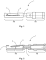
- the Figure 1 shows a socket contact 1 according to the invention.
- the socket contact 1 has a hollow cylindrical connection area AB on the connection side for receiving a stripped end area of an electrical conductor to be connected (not shown).
- the connection area AB is designed as a crimp connection.
- the socket contact 1 On the plug-in side, the socket contact 1 has a hollow cylindrical contact area KB with a pin insertion opening 2 for receiving a suitable contact pin (not shown for illustrative reasons).
- the connection area AB and the contact area KB are connected to one another via a solid web 3.
- the contact area KB has a cylinder wall with a contact tongue 4 folded radially inwards.
- the contact tongue 4 points with its free end towards the pin insertion opening 2.
- the cylinder wall of the The contact area KB has a circumferential groove 5 in the attachment area, i.e. where the contact tongue is bent radially inwards.
- the center of this groove can also be eccentric to the center of the hollow cylinder of the socket contact. This can also create a groove that is not visible all the way around.
- the contact area KB has an insertion depth T for the contact pin.
- the contact tongue 4 has a length I.
- the length I is between 40% and 95% of the insertion depth T. This means that the ratio of I/T is between 0.4 and 0.95.
- a slot inclined at approximately 45° to the plug-in direction is provided in the cylinder wall of the contact area KB. This means that the free end of the contact tongue 4 is designed at an angle.
Landscapes
- Coupling Device And Connection With Printed Circuit (AREA)
- Manufacturing Of Electrical Connectors (AREA)
- Connector Housings Or Holding Contact Members (AREA)
Description
- Die Erfindung geht aus von einem Buchsenkontakt nach der Gattung des unabhängigen Anspruchs 1.
- Derartige Buchsenkontakte werden in Steckverbindern zur Übertragung elektrischer Ströme, Signale und/oder Daten eingesetzt.
- Die
DE 1 640 554 A1 zeigt einen Buchsenkontakt, der aus einem flachen Federstahlblech mithilfe der Stanzbiegetechnik hergestellt ist. Der Kontaktbereich des Buchsenkontakt weist eine radial nach innen, mehrfach gefaltete Kontaktzunge auf. - Die
US 5 135 417 A zeigt einen in eine Mantelhülse eingebrachten Buchsenkontakt. Der Buchsenkontakt ist in Stanz-Biegetechnik gefertigt und weist in seinem Kontaktbereich etwa mittig eine umlaufende Kerbe auf, die dazu dient den elektrischen Kontakt zum Kontaktstift zu verbessern. - Das verwendete Federstahlblech kann einfach verarbeitet werden. Jedoch ist die Stromtragfähigkeit eines daraus hergestellten Buchsenkontakts nicht immer ausreichend.
- Die
US 2 280 027 A zeigt einen Buchsenkontakt mit einem hohlzylindrischen Kontaktbereich aus dem eine Kontaktzunge herausgearbeitet ist. In die Kontaktzunge wird ein Loch eingebracht, in welches ein Werkzeug eingeführt wird, um die Kontaktzunge innenseitig einzustanzen. An dieser Stanzkante wird die Kontaktzunge radial nach innen gebogen. - Kontaktbuchsen, die aus Massivmaterial hergestellt sind, bieten hier bessere elektrische Eigenschaften. Wird ein solcher Buchsenkontakt aus einem Massivmaterial, beispielsweise einem Drahtstück entsprechenden Durchmessers, hergestellt, kann es vorkommen, dass die Kontaktzunge durch den Biegeprozess am Ansatz brüchig wird. Außerdem weisen derartige Buchsenkontakte Schwankungen bei den so genannten Abzugskräften, bei der der Kontaktstift aus der Kontaktbuchse gezogen wird, auf. Dies hat zur Folge, dass die Abzugskraft immer auf die obere Toleranzgrenze eingestellt wird, was insgesamt zu hohen Abzugkräften führt.
- Das Deutsche Patent- und Markenamt hat in der Prioritätsanmeldung zu vorliegender Anmeldung den folgenden Stand der Technik recherchiert:
DE 200 08 846 U1 ,DE 20 24 031 A ,DE 11 98 891 B ,DE 16 40 554 A undWO 2019/ 206 784 A1 . - Die Aufgabe der Erfindung besteht darin einen einfach herstellbaren Buchsenkontakt vorzuschlagen. Der Buchsenkontakt soll außerdem einen zuverlässigen elektrischen Kontakt mit einem passenden Stiftkontakt aufweisen.
- Die Aufgabe wird durch den Gegenstand der unabhängigen Ansprüche gelöst.
- Vorteilhafte Ausgestaltungen der Erfindung sind in den Unteransprüchen und der folgenden Beschreibung angegeben.
- Der erfindungsgemäße Buchsenkontakt weist einen hohlzylindrischen Anschlussbereich auf. Der Anschlussbereich ist zur Aufnahme eines abisolierten Endbereichs eines anzuschließenden elektrischen Leiters vorgesehen. Der abisolierte Endabschnitt wird in den hohlzylindrischen Anschlussbereich eingeführt. Anschließend wird der Anschlussbereich mit einer so genannten Crimpzange verquetscht, wodurch eine zuverlässig elektrisch leitende Verbindung zwischen dem Leiter und dem Buchsenkontakt entsteht. Man spricht hier auch von einem Crimpanschluss.
- Um einen zuverlässigen Crimpanschluss zu gewährleisten, hat es sich als vorteilhaft erwiesen, wenn der Anschlussbereich eine Wandstärke von 0,5 mm bis zu 1 mm aufweist.
- Der Buchsenkontakt weist einen hohlzylindrischen Kontaktbereich auf. Der Kontaktbereich weist eine Stifteinführöffnung zur Aufnahme eines
- Kontaktstifts auf. Der Kontaktstift wird zur elektrischen Kontaktierung axial in den Kontaktbereich eingeführt.
- Der Kontaktbereich weist eine Zylinderwandung auf. Aus der Zylinderwandung ist in einem bevorzugt spanenden Arbeitsschritt zumindest eine Kontaktzunge herausgearbeitet, die radial nach innen gefaltet ist. Das freie Ende der Kontaktzunge weist dabei zur bzw. in Richtung der Stifteinführöffnung.
- Das feste Ende der Kontaktzunge weist einen so genannten Ansatz an der Zylinderwandung des Kontaktbereichs auf. Am Ansatz ist die Kontaktzunge radial nach innen gefaltet. Im Bereich dieser Faltung bzw. des Ansatzes ist in der Zylinderwandung eine zumindest teilweise umlaufende Nut eingebracht. Es hat sich erwiesen, dass durch diese Nut insbesondere ein Brüchigwerden am Ansatzbereich der Kontaktzunge verhindert werden kann. Durch das Einbringen dieser Nut knickt die Kontaktzunge deutlich gleichmäßiger ab. Das führt dazu, dass die Abzugkräfte, also wenn ein Kontaktstift aus der Kontaktbuchse gezogen wird, bei einer Vielzahl gleichartiger Kontaktbuchsen deutlich gleichmäßiger sind. Dadurch wird die Produktqualität erhöht.
- Die Erfindung besteht insbesondere darin durch die Nut der Kontaktlamelle eine damit eine feste Position zur Verformung vorzugeben. Dadurch zeigt der Endabschnitt der Kontaktzunge geometrisch gleichmäßiger im Raum, also in den zylinderförmigen Kontaktbereich der Kontaktbuchse.
- Wird ein passender Stiftkontakt in den Buchsenkontakt eingeschoben, wird die Kontaktzunge gegen die Mantelfläche des Stiftkontakts gedrückt. Hierdurch wird der Stiftkontakt insbesondere mit der Innenwand des Kontaktbereichs in Berührkontakt gebracht. In Summe wird hierdurch eine zuverlässige elektrische Kontaktierung zwischen Buchsenkontakt und Stiftkontakt geschaffen.
- Vorzugsweise weist der Buchsenkontakt genau eine radial nach innen gefaltete und mit ihrem freien Ende zur Stifteinführöffnung weisende Kontaktzunge auf. Hierdurch kann der Buchsenkontakt kostengünstiger hergestellt werden.
- Vorteilhafterweise hat die Nut einen dreieckigen Querschnitt. Der Winkel im Tiefenbereich der Nut liegt vorzugsweise zwischen 45°und 120°. Die Nut hat vorzugsweise eine Tiefe von 0,01 mm bis zu 0,35 mm, besonders bevorzugt jedoch von 0,1 mm bis 0,3 mm. Eine derartige Geometrie hat sich zur oben erwähnten Bruchvermeidung in Tests als besonders geeignet erwiesen.
- Ein trapezförmiger oder sinusförmiger Querschnitt der Nut kann alternativ gewählt werden.
- Besonders vorteilhaft ist es, wenn die Zylinderwandung im Bereich der Faltung für die Kontaktzunge eine vollständig umlaufende Nut aufweist. Zur Bruchvermeidung ist eine vollständige Nut nicht unbedingt notwendig. Fertigungstechnisch hat eine solche Nut jedoch Vorteile.
- Der Kontaktbereich weist eine bestimmte Einstecktiefe für einen passenden Kontaktstift auf. In einer besonders vorteilhaften Ausgestaltung der Erfindung beträgt die Länge der Kontaktzunge zwischen 40% und 95% der Einstecktiefe des Kontaktbereichs. Mit der Länge der Kontaktzunge wird die Steifigkeit der Kontaktzunge festgelegt. Die Kraft, mit welcher die Kontaktzunge auf den Stiftkontakt drückt, wird durch die so genannte Anstellung der Zunge festgelegt. Hierdurch werden auch die Steck- und Ziehkräfte beeinflusst.
- Ein Ausführungsbeispiel der Erfindung ist in den Zeichnungen dargestellt und wird im Folgenden näher erläutert. Es zeigen:
- Fig. 1
- eine Seitenansicht eines erfindungsgemäßen Buchsenkontakts und
- Fig. 2
- eine Schnittdarstellung des erfindungsgemäßen Buchsenkontakts.
- Die Figuren enthalten teilweise vereinfachte, schematische Darstellungen. Zum Teil werden für gleiche, aber gegebenenfalls nicht identische Elemente identische Bezugszeichen verwendet. Verschiedene Ansichten gleicher Elemente könnten unterschiedlich skaliert sein.
- Der erfindungsgemäße Buchsenkontakt 1 wird aus einem massiven Drahtstück durch insbesondere spanende Arbeitsschritte hergestellt.
- Die
Figur 1 zeigt einen erfindungsgemäßen Buchsenkontakt 1. Der Buchsenkontakt 1 weist anschlussseitig einen hohlzylindrischen Anschlussbereich AB zur Aufnahme eines abisolierten Endbereichs eines anzuschließenden elektrischen Leiters (nicht gezeigt) auf. Der Anschlussbereich AB ist als Crimpanschluss ausgebildet. - Steckseitig weist der Buchsenkontakt 1 einen hohlzylindrischen Kontaktbereich KB mit einer Stifteinführöffnung 2 zur Aufnahme eines passenden Kontaktstifts (aus darstellerischen Gründen nicht gezeigt) auf. Der Anschlussbereich AB und der Kontaktbereich KB sind über einen massiven Steg 3 miteinander verbunden.
- Der Kontaktbereich KB weist eine Zylinderwandung mit einer radial nach innen gefalteten Kontaktzunge 4 auf. Die Kontaktzunge 4 zeigt mit ihrem freien Ende zur Stifteinführöffnung 2. Die Zylinderwandung des Kontaktbereichs KB weist im Ansatzbereich, d.h. dort wo die Kontaktzunge radial nach innen gebogen ist, eine umlaufende Nut 5 auf.
- Der Mittelpunkt dieser Nut kann auch exzentrisch zum Mittelpunkt des Hohlzylinders des Buchsenkontakts liegen. Dadurch kann auch eine nicht umlaufend sichtbare Nut entstehen.
- Der Kontaktbereich KB weist eine Einstecktiefe T für den Kontaktstift auf. Die Kontaktzunge 4 weist eine Länge I auf. Die Länge I beträgt zwischen 40% und 95% von der Einstecktiefe T. Das bedeutet, dass das Verhältnis von I/T zwischen 0,4 und 0,95 beträgt.
- In der Zylinderwandung des Kontaktbereichs KB ist ein um etwa 45° zur Steckrichtung geneigter Schlitz eingebracht. Dadurch ist das freie Ende der Kontaktzunge 4 schräg ausgestaltet.
- Auch wenn in den Figuren verschiedene Aspekte oder Merkmale der Erfindung jeweils in Kombination gezeigt sind, ist für den Fachmann - soweit nicht anders angegeben - ersichtlich, dass die dargestellten und diskutierten Kombinationen nicht die einzig möglichen sind. Insbesondere können einander entsprechende Einheiten oder Merkmalskomplexe aus unterschiedlichen Ausführungsbeispielen miteinander ausgetauscht werden.
-
- 1
- Buchsenkontakt
- 2
- Stifteinführöffnung
- 3
- Steg
- 4
- Kontaktzunge
- 5
- Nut
- AB
- Anschlussbereich
- KB
- Kontaktbereich
- I
- Länge
- T
- Tiefe
Claims (9)
- Ein aus Vollmaterial ausgearbeiteter Buchsenkontakt (1), welcher einen hohlzylindrischen Anschlussbereich (AB) zur Aufnahme eines abisolierten Endbereichs eines anzuschließenden elektrischen Leiters und einen hohlzylindrischen Kontaktbereich (KB) mit einer Stifteinführöffnung (2) zur Aufnahme eines Kontaktstifts aufweist,wobei der Kontaktbereich (KB) eine Zylinderwandung aufweist, wobei aus der Zylinderwandung zumindest eine Kontaktzunge herausgearbeitet ist, der Buchsenkontakt ist dadurch gekennzeichnet, dass ein festes Ende der Kontaktzunge einen Ansatz am hohlzylindrischen Kontaktbereich aufweist,wobei im Bereich des Ansatzes außenseitig in der Zylinderwandung eine zumindest teilweise umlaufende Nut eingebracht ist und dass die Kontaktzunge an diesem Ansatz radial nach innen gefaltet ist und mit ihrem freien Ende zur Stifteinführöffnung (2) weist.
- Buchsenkontakt (1) nach Anspruch 1
dadurch gekennzeichnet, dass
der Buchsenkontakt (1) genau eine radial nach innen gefaltete und mit ihrem freien Ende zur Stifteinführöffnung (2) weisende Kontaktzunge (4) aufweist. - Buchsenkontakt (1) nach einem der vorstehenden Ansprüche dadurch gekennzeichnet, dass
der Kontaktbereich (KB) eine Einstecktiefe (T) für den Kontaktstift aufweist und dass die Kontaktzunge (4) eine Länge (I) aufweist, die zwischen 40% und 95% der Einstecktiefe (T) beträgt. - Buchsenkontakt (1) nach einem der vorstehenden Ansprüche dadurch gekennzeichnet, dass
die Nut (5) einen dreieckigen, trapezförmigen oder sinusförmigen Querschnitt aufweist. - Buchsenkontakt (1) nach einem der vorstehenden Ansprüche dadurch gekennzeichnet, dass
die Nut (5) eine Tiefe von 0,01 mm bis zu 0,35 mm, besonders bevorzugt jedoch von 0,1 mm bis 0,3 mm, aufweist. - Buchsenkontakt (1) nach einem der vorstehenden Ansprüche dadurch gekennzeichnet, dass
die Stifteinführöffnung (2) einen Durchmesser von 1,5 mm bis zu 2,5 mm aufweist. - Buchsenkontakt (1) nach einem der vorstehenden Ansprüche 1-2 dadurch gekennzeichnet, dass
die Zylinderwandung im Bereich der Faltung für die Kontaktzunge (4) eine vollständig umlaufende Nut (5) aufweist. - Buchsenkontakt (1) nach einem der vorstehenden Ansprüche dadurch gekennzeichnet, dass
der Anschlussbereich (AB) als Crimpanschluss ausgebildet ist. - Buchsenkontakt (1) nach einem der vorstehenden Ansprüche dadurch gekennzeichnet, dass
der Anschlussbereich (AB) eine Wandstärke von 0,5 mm bis zu 1 mm aufweist.
Applications Claiming Priority (2)
| Application Number | Priority Date | Filing Date | Title |
|---|---|---|---|
| DE102019134564.2A DE102019134564B4 (de) | 2019-12-16 | 2019-12-16 | Buchsenkontakt |
| PCT/DE2020/101045 WO2021121473A1 (de) | 2019-12-16 | 2020-12-10 | Buchsenkontakt |
Publications (2)
| Publication Number | Publication Date |
|---|---|
| EP4078733A1 EP4078733A1 (de) | 2022-10-26 |
| EP4078733B1 true EP4078733B1 (de) | 2024-10-16 |
Family
ID=74141233
Family Applications (1)
| Application Number | Title | Priority Date | Filing Date |
|---|---|---|---|
| EP20838341.4A Active EP4078733B1 (de) | 2019-12-16 | 2020-12-10 | Buchsenkontakt |
Country Status (6)
| Country | Link |
|---|---|
| US (1) | US12119581B2 (de) |
| EP (1) | EP4078733B1 (de) |
| KR (1) | KR102694679B1 (de) |
| CN (1) | CN114830455A (de) |
| DE (1) | DE102019134564B4 (de) |
| WO (1) | WO2021121473A1 (de) |
Family Cites Families (19)
| Publication number | Priority date | Publication date | Assignee | Title |
|---|---|---|---|---|
| US2280027A (en) | 1940-08-30 | 1942-04-14 | Joseph A Bottomley | Cable connector |
| US3129050A (en) | 1960-10-06 | 1964-04-14 | Burndy Corp | Electrical connectors |
| US3406376A (en) * | 1966-09-26 | 1968-10-15 | Itt | Socket contact and method of manufacture |
| DE2024031A1 (de) * | 1970-05-16 | 1971-12-02 | Blaupunkt Werke Gmbh | Isolierstoffgehäuse für eine elektrische Flachsteckverbindung |
| US5135417A (en) | 1991-07-02 | 1992-08-04 | Augat/Altair International Inc. | Dual usage electrical/electronic pin terminal system |
| DE20008846U1 (de) * | 2000-05-17 | 2000-08-03 | Harting Kgaa | Kontaktelement |
| DE20119530U1 (de) * | 2001-12-01 | 2002-04-18 | HARTING Electric GmbH & Co. KG, 32339 Espelkamp | Elektrisches Kontaktelement |
| JP2003217557A (ja) | 2002-01-21 | 2003-07-31 | Tocad Energy Co Ltd | リード板折り曲げ構造 |
| US20040224575A1 (en) * | 2002-09-19 | 2004-11-11 | Craig H. Baker | Low insertion force electrical socket contact |
| US6790101B1 (en) * | 2003-07-15 | 2004-09-14 | Molex Incorporated | Female terminal with sacrificial arc discharge contacts |
| TWM336644U (en) * | 2008-01-28 | 2008-07-11 | Inventec Appliances Corp | Conducting clad laminate with bent wires |
| WO2015056691A1 (ja) * | 2013-10-15 | 2015-04-23 | 古河As株式会社 | 端子、ワイヤハーネスおよびワイヤハーネス構造体 |
| JP2016024902A (ja) * | 2014-07-17 | 2016-02-08 | 矢崎総業株式会社 | 雌型電気接触部及び雌型電気接触部の形成方法 |
| JP2018067496A (ja) * | 2016-10-21 | 2018-04-26 | 住友電装株式会社 | シールド端子及び外導体端子 |
| US9917390B1 (en) * | 2016-12-13 | 2018-03-13 | Carlisle Interconnect Technologies, Inc. | Multiple piece contact for an electrical connector |
| JP6787175B2 (ja) * | 2017-02-22 | 2020-11-18 | 株式会社オートネットワーク技術研究所 | 多接点型端子 |
| US9966708B1 (en) * | 2017-05-30 | 2018-05-08 | Arlington Industries, Inc. | Electrical fitting for snap connection of electrical cable to a junction box |
| CN107394445B (zh) * | 2017-08-29 | 2023-08-08 | 实盈电子(东莞)有限公司 | 一种充电枪用导电连接件 |
| WO2019206784A1 (de) * | 2018-04-24 | 2019-10-31 | Stäubli Electrical Connectors Ag | Buchsenkörper |
-
2019
- 2019-12-16 DE DE102019134564.2A patent/DE102019134564B4/de active Active
-
2020
- 2020-12-10 WO PCT/DE2020/101045 patent/WO2021121473A1/de not_active Ceased
- 2020-12-10 EP EP20838341.4A patent/EP4078733B1/de active Active
- 2020-12-10 US US17/777,379 patent/US12119581B2/en active Active
- 2020-12-10 KR KR1020227024499A patent/KR102694679B1/ko active Active
- 2020-12-10 CN CN202080087597.1A patent/CN114830455A/zh active Pending
Also Published As
| Publication number | Publication date |
|---|---|
| KR20220112837A (ko) | 2022-08-11 |
| DE102019134564A1 (de) | 2021-06-17 |
| US20220407257A1 (en) | 2022-12-22 |
| WO2021121473A1 (de) | 2021-06-24 |
| KR102694679B1 (ko) | 2024-08-14 |
| CN114830455A (zh) | 2022-07-29 |
| DE102019134564B4 (de) | 2022-08-04 |
| US12119581B2 (en) | 2024-10-15 |
| EP4078733A1 (de) | 2022-10-26 |
Similar Documents
| Publication | Publication Date | Title |
|---|---|---|
| EP2569825B1 (de) | Elektrisches kontaktelement | |
| EP2255412B1 (de) | Elektrische anschlusseinrichtung | |
| EP3251174B1 (de) | Steckverbinderanordnung mit kompensationscrimp | |
| DE102011101341B4 (de) | Gestanzte elektrische Kontaktanordnung und Verfahren zur Herstellung einer gestanzten elektrischen Kontaktanordnung | |
| EP1997191B1 (de) | Rastbarer Radsok-Steckverbinder | |
| DE102007055040B4 (de) | Kontaktelement und Verfahren zur Herstellung eines Kontaktelementes | |
| EP2596552B1 (de) | Crimphülse für quetschverbindungen | |
| DE102012106741B4 (de) | Kontaktelement | |
| EP4078733B1 (de) | Buchsenkontakt | |
| EP0968548A1 (de) | Steckerbuchse mit in der form eines hyperboloids angeordneten kontaktbereichen | |
| EP0918368B1 (de) | Anschlussorgan für elektrische Leitungen | |
| DE102017218825B4 (de) | Verfahren zur elektrischen Kontaktierung einer elektrischen Maschine sowie elektrische Maschine mit dieser Kontaktierung | |
| LU500419B1 (de) | Verbindungsanordnung mit Crimpverbindung und Verfahren zur Herstellung einer Verbindungsanordnung mit Crimpverbindung | |
| DE102008062597B3 (de) | Verbindungselement mit mindestens einem elektrischen Steckkontakt und Verfahen zur Herstellung desselben | |
| WO2019121809A1 (de) | Elektrisches kontaktierelement und herstellungsverfahren | |
| WO2024068558A1 (de) | Hybrides kontaktelement | |
| EP3707780B1 (de) | Kontaktelement mit einem klemmenden anschluss für litzenleiter | |
| DE102009057944B3 (de) | Kontaktbuchse zur Aufnahme eines Kontaktstiftes | |
| DE102021117926A1 (de) | Verbindungsanordnung mit Crimpverbindung und Verfahren zur Herstellung einer Verbindungsanordnung mit Crimpverbindung | |
| DE202024100328U1 (de) | Verbesserte Presshülse zum Verbinden eines Leiterabschnitts mit einer Presshülse | |
| EP4210174A1 (de) | Verbesserte leitfähige hülse und verfahren zum verbinden eines leiterabschnitts mit der leitfähigen hülse | |
| DE102023132087A1 (de) | Leitungssatz mit Steckverbinder | |
| DE102022213638A1 (de) | Crimpkontaktelement und Verbindungsanordnung | |
| EP3182529A1 (de) | Schleifringeinheit | |
| DE102020132866A1 (de) | Kontaktelement für einen Stecker zum elektrischen Kontaktieren einer Litze mittels Crimpen |
Legal Events
| Date | Code | Title | Description |
|---|---|---|---|
| STAA | Information on the status of an ep patent application or granted ep patent |
Free format text: STATUS: UNKNOWN |
|
| STAA | Information on the status of an ep patent application or granted ep patent |
Free format text: STATUS: THE INTERNATIONAL PUBLICATION HAS BEEN MADE |
|
| PUAI | Public reference made under article 153(3) epc to a published international application that has entered the european phase |
Free format text: ORIGINAL CODE: 0009012 |
|
| STAA | Information on the status of an ep patent application or granted ep patent |
Free format text: STATUS: REQUEST FOR EXAMINATION WAS MADE |
|
| 17P | Request for examination filed |
Effective date: 20220505 |
|
| AK | Designated contracting states |
Kind code of ref document: A1 Designated state(s): AL AT BE BG CH CY CZ DE DK EE ES FI FR GB GR HR HU IE IS IT LI LT LU LV MC MK MT NL NO PL PT RO RS SE SI SK SM TR |
|
| DAV | Request for validation of the european patent (deleted) | ||
| DAX | Request for extension of the european patent (deleted) | ||
| P01 | Opt-out of the competence of the unified patent court (upc) registered |
Effective date: 20230603 |
|
| GRAP | Despatch of communication of intention to grant a patent |
Free format text: ORIGINAL CODE: EPIDOSNIGR1 |
|
| STAA | Information on the status of an ep patent application or granted ep patent |
Free format text: STATUS: GRANT OF PATENT IS INTENDED |
|
| INTG | Intention to grant announced |
Effective date: 20240716 |
|
| GRAS | Grant fee paid |
Free format text: ORIGINAL CODE: EPIDOSNIGR3 |
|
| GRAA | (expected) grant |
Free format text: ORIGINAL CODE: 0009210 |
|
| STAA | Information on the status of an ep patent application or granted ep patent |
Free format text: STATUS: THE PATENT HAS BEEN GRANTED |
|
| AK | Designated contracting states |
Kind code of ref document: B1 Designated state(s): AL AT BE BG CH CY CZ DE DK EE ES FI FR GB GR HR HU IE IS IT LI LT LU LV MC MK MT NL NO PL PT RO RS SE SI SK SM TR |
|
| REG | Reference to a national code |
Ref country code: GB Ref legal event code: FG4D Free format text: NOT ENGLISH |
|
| REG | Reference to a national code |
Ref country code: CH Ref legal event code: EP |
|
| REG | Reference to a national code |
Ref country code: IE Ref legal event code: FG4D Free format text: LANGUAGE OF EP DOCUMENT: GERMAN |
|
| REG | Reference to a national code |
Ref country code: DE Ref legal event code: R096 Ref document number: 502020009530 Country of ref document: DE |
|
| PGFP | Annual fee paid to national office [announced via postgrant information from national office to epo] |
Ref country code: GB Payment date: 20241223 Year of fee payment: 5 |
|
| PGFP | Annual fee paid to national office [announced via postgrant information from national office to epo] |
Ref country code: FR Payment date: 20241227 Year of fee payment: 5 |
|
| REG | Reference to a national code |
Ref country code: LT Ref legal event code: MG9D |
|
| REG | Reference to a national code |
Ref country code: NL Ref legal event code: MP Effective date: 20241016 |
|
| PG25 | Lapsed in a contracting state [announced via postgrant information from national office to epo] |
Ref country code: NL Free format text: LAPSE BECAUSE OF FAILURE TO SUBMIT A TRANSLATION OF THE DESCRIPTION OR TO PAY THE FEE WITHIN THE PRESCRIBED TIME-LIMIT Effective date: 20241016 |
|
| PG25 | Lapsed in a contracting state [announced via postgrant information from national office to epo] |
Ref country code: NL Free format text: LAPSE BECAUSE OF FAILURE TO SUBMIT A TRANSLATION OF THE DESCRIPTION OR TO PAY THE FEE WITHIN THE PRESCRIBED TIME-LIMIT Effective date: 20241016 |
|
| PG25 | Lapsed in a contracting state [announced via postgrant information from national office to epo] |
Ref country code: IS Free format text: LAPSE BECAUSE OF FAILURE TO SUBMIT A TRANSLATION OF THE DESCRIPTION OR TO PAY THE FEE WITHIN THE PRESCRIBED TIME-LIMIT Effective date: 20250216 Ref country code: HR Free format text: LAPSE BECAUSE OF FAILURE TO SUBMIT A TRANSLATION OF THE DESCRIPTION OR TO PAY THE FEE WITHIN THE PRESCRIBED TIME-LIMIT Effective date: 20241016 Ref country code: PT Free format text: LAPSE BECAUSE OF FAILURE TO SUBMIT A TRANSLATION OF THE DESCRIPTION OR TO PAY THE FEE WITHIN THE PRESCRIBED TIME-LIMIT Effective date: 20250217 |
|
| PGFP | Annual fee paid to national office [announced via postgrant information from national office to epo] |
Ref country code: DE Payment date: 20241227 Year of fee payment: 5 |
|
| PG25 | Lapsed in a contracting state [announced via postgrant information from national office to epo] |
Ref country code: FI Free format text: LAPSE BECAUSE OF FAILURE TO SUBMIT A TRANSLATION OF THE DESCRIPTION OR TO PAY THE FEE WITHIN THE PRESCRIBED TIME-LIMIT Effective date: 20241016 |
|
| PG25 | Lapsed in a contracting state [announced via postgrant information from national office to epo] |
Ref country code: BG Free format text: LAPSE BECAUSE OF FAILURE TO SUBMIT A TRANSLATION OF THE DESCRIPTION OR TO PAY THE FEE WITHIN THE PRESCRIBED TIME-LIMIT Effective date: 20241016 |
|
| PG25 | Lapsed in a contracting state [announced via postgrant information from national office to epo] |
Ref country code: ES Free format text: LAPSE BECAUSE OF FAILURE TO SUBMIT A TRANSLATION OF THE DESCRIPTION OR TO PAY THE FEE WITHIN THE PRESCRIBED TIME-LIMIT Effective date: 20241016 |
|
| PG25 | Lapsed in a contracting state [announced via postgrant information from national office to epo] |
Ref country code: NO Free format text: LAPSE BECAUSE OF FAILURE TO SUBMIT A TRANSLATION OF THE DESCRIPTION OR TO PAY THE FEE WITHIN THE PRESCRIBED TIME-LIMIT Effective date: 20250116 |
|
| PG25 | Lapsed in a contracting state [announced via postgrant information from national office to epo] |
Ref country code: LV Free format text: LAPSE BECAUSE OF FAILURE TO SUBMIT A TRANSLATION OF THE DESCRIPTION OR TO PAY THE FEE WITHIN THE PRESCRIBED TIME-LIMIT Effective date: 20241016 Ref country code: GR Free format text: LAPSE BECAUSE OF FAILURE TO SUBMIT A TRANSLATION OF THE DESCRIPTION OR TO PAY THE FEE WITHIN THE PRESCRIBED TIME-LIMIT Effective date: 20250117 |
|
| PG25 | Lapsed in a contracting state [announced via postgrant information from national office to epo] |
Ref country code: PL Free format text: LAPSE BECAUSE OF FAILURE TO SUBMIT A TRANSLATION OF THE DESCRIPTION OR TO PAY THE FEE WITHIN THE PRESCRIBED TIME-LIMIT Effective date: 20241016 |
|
| PGFP | Annual fee paid to national office [announced via postgrant information from national office to epo] |
Ref country code: IT Payment date: 20241223 Year of fee payment: 5 |
|
| PG25 | Lapsed in a contracting state [announced via postgrant information from national office to epo] |
Ref country code: RS Free format text: LAPSE BECAUSE OF FAILURE TO SUBMIT A TRANSLATION OF THE DESCRIPTION OR TO PAY THE FEE WITHIN THE PRESCRIBED TIME-LIMIT Effective date: 20250116 |
|
| PG25 | Lapsed in a contracting state [announced via postgrant information from national office to epo] |
Ref country code: SM Free format text: LAPSE BECAUSE OF FAILURE TO SUBMIT A TRANSLATION OF THE DESCRIPTION OR TO PAY THE FEE WITHIN THE PRESCRIBED TIME-LIMIT Effective date: 20241016 |
|
| PG25 | Lapsed in a contracting state [announced via postgrant information from national office to epo] |
Ref country code: MC Free format text: LAPSE BECAUSE OF FAILURE TO SUBMIT A TRANSLATION OF THE DESCRIPTION OR TO PAY THE FEE WITHIN THE PRESCRIBED TIME-LIMIT Effective date: 20241016 |
|
| PG25 | Lapsed in a contracting state [announced via postgrant information from national office to epo] |
Ref country code: DK Free format text: LAPSE BECAUSE OF FAILURE TO SUBMIT A TRANSLATION OF THE DESCRIPTION OR TO PAY THE FEE WITHIN THE PRESCRIBED TIME-LIMIT Effective date: 20241016 |
|
| REG | Reference to a national code |
Ref country code: DE Ref legal event code: R097 Ref document number: 502020009530 Country of ref document: DE |
|
| PG25 | Lapsed in a contracting state [announced via postgrant information from national office to epo] |
Ref country code: EE Free format text: LAPSE BECAUSE OF FAILURE TO SUBMIT A TRANSLATION OF THE DESCRIPTION OR TO PAY THE FEE WITHIN THE PRESCRIBED TIME-LIMIT Effective date: 20241016 |
|
| PG25 | Lapsed in a contracting state [announced via postgrant information from national office to epo] |
Ref country code: RO Free format text: LAPSE BECAUSE OF FAILURE TO SUBMIT A TRANSLATION OF THE DESCRIPTION OR TO PAY THE FEE WITHIN THE PRESCRIBED TIME-LIMIT Effective date: 20241016 |
|
| PG25 | Lapsed in a contracting state [announced via postgrant information from national office to epo] |
Ref country code: SK Free format text: LAPSE BECAUSE OF FAILURE TO SUBMIT A TRANSLATION OF THE DESCRIPTION OR TO PAY THE FEE WITHIN THE PRESCRIBED TIME-LIMIT Effective date: 20241016 |
|
| PG25 | Lapsed in a contracting state [announced via postgrant information from national office to epo] |
Ref country code: CZ Free format text: LAPSE BECAUSE OF FAILURE TO SUBMIT A TRANSLATION OF THE DESCRIPTION OR TO PAY THE FEE WITHIN THE PRESCRIBED TIME-LIMIT Effective date: 20241016 |
|
| REG | Reference to a national code |
Ref country code: CH Ref legal event code: PL |
|
| PG25 | Lapsed in a contracting state [announced via postgrant information from national office to epo] |
Ref country code: LU Free format text: LAPSE BECAUSE OF NON-PAYMENT OF DUE FEES Effective date: 20241210 |
|
| PLBE | No opposition filed within time limit |
Free format text: ORIGINAL CODE: 0009261 |
|
| STAA | Information on the status of an ep patent application or granted ep patent |
Free format text: STATUS: NO OPPOSITION FILED WITHIN TIME LIMIT |
|
| PG25 | Lapsed in a contracting state [announced via postgrant information from national office to epo] |
Ref country code: SE Free format text: LAPSE BECAUSE OF FAILURE TO SUBMIT A TRANSLATION OF THE DESCRIPTION OR TO PAY THE FEE WITHIN THE PRESCRIBED TIME-LIMIT Effective date: 20241016 |
|
| 26N | No opposition filed |
Effective date: 20250717 |
|
| REG | Reference to a national code |
Ref country code: BE Ref legal event code: MM Effective date: 20241231 |
|
| PG25 | Lapsed in a contracting state [announced via postgrant information from national office to epo] |
Ref country code: BE Free format text: LAPSE BECAUSE OF NON-PAYMENT OF DUE FEES Effective date: 20241231 |
|
| PG25 | Lapsed in a contracting state [announced via postgrant information from national office to epo] |
Ref country code: CH Free format text: LAPSE BECAUSE OF NON-PAYMENT OF DUE FEES Effective date: 20241231 |
|
| PG25 | Lapsed in a contracting state [announced via postgrant information from national office to epo] |
Ref country code: IE Free format text: LAPSE BECAUSE OF NON-PAYMENT OF DUE FEES Effective date: 20241210 |