EP4078728B1 - Doppelpolarisationsantenne - Google Patents
Doppelpolarisationsantenne Download PDFInfo
- Publication number
- EP4078728B1 EP4078728B1 EP20824690.0A EP20824690A EP4078728B1 EP 4078728 B1 EP4078728 B1 EP 4078728B1 EP 20824690 A EP20824690 A EP 20824690A EP 4078728 B1 EP4078728 B1 EP 4078728B1
- Authority
- EP
- European Patent Office
- Prior art keywords
- antenna
- polarization
- blades
- antenna according
- lhcp
- Prior art date
- Legal status (The legal status is an assumption and is not a legal conclusion. Google has not performed a legal analysis and makes no representation as to the accuracy of the status listed.)
- Active
Links
Images


Classifications
-
- H—ELECTRICITY
- H01—ELECTRIC ELEMENTS
- H01Q—ANTENNAS, i.e. RADIO AERIALS
- H01Q21/00—Antenna arrays or systems
- H01Q21/06—Arrays of individually energised antenna units similarly polarised and spaced apart
- H01Q21/061—Two dimensional planar arrays
- H01Q21/064—Two dimensional planar arrays using horn or slot aerials
-
- H—ELECTRICITY
- H01—ELECTRIC ELEMENTS
- H01Q—ANTENNAS, i.e. RADIO AERIALS
- H01Q21/00—Antenna arrays or systems
- H01Q21/24—Combinations of antenna units polarised in different directions for transmitting or receiving circularly and elliptically polarised waves or waves linearly polarised in any direction
-
- H—ELECTRICITY
- H01—ELECTRIC ELEMENTS
- H01P—WAVEGUIDES; RESONATORS, LINES, OR OTHER DEVICES OF THE WAVEGUIDE TYPE
- H01P5/00—Coupling devices of the waveguide type
- H01P5/12—Coupling devices having more than two ports
-
- H—ELECTRICITY
- H01—ELECTRIC ELEMENTS
- H01Q—ANTENNAS, i.e. RADIO AERIALS
- H01Q1/00—Details of, or arrangements associated with, antennas
- H01Q1/27—Adaptation for use in or on movable bodies
- H01Q1/28—Adaptation for use in or on aircraft, missiles, satellites, or balloons
- H01Q1/288—Satellite antennas
-
- H—ELECTRICITY
- H01—ELECTRIC ELEMENTS
- H01Q—ANTENNAS, i.e. RADIO AERIALS
- H01Q13/00—Waveguide horns or mouths; Slot antennas; Leaky-waveguide antennas; Equivalent structures causing radiation along the transmission path of a guided wave
- H01Q13/02—Waveguide horns
- H01Q13/025—Multimode horn antennas; Horns using higher mode of propagation
- H01Q13/0258—Orthomode horns
-
- H—ELECTRICITY
- H01—ELECTRIC ELEMENTS
- H01Q—ANTENNAS, i.e. RADIO AERIALS
- H01Q21/00—Antenna arrays or systems
- H01Q21/0006—Particular feeding systems
Definitions
- the present invention relates to a radio frequency (RF) module, intended to form the passive part of a direct radiating antenna (DRA, Direct Radiating Array).
- RF radio frequency
- Antennas are elements that are used to emit electromagnetic signals into free space, or to receive such signals.
- Simple antennas such as dipoles, have limited performance in terms of gain and directivity.
- Parabolic antennas allow higher directivity, but are bulky and heavy, which makes their use unsuitable in applications such as satellites for example, where weight and volume must be reduced.
- DRA antenna arrays are also known which bring together several radiating elements (antenna elements) out of phase in order to improve gain and directivity.
- the signals received on the different radiant elements, or emitted by these elements, are amplified and phase shifted between them so as to control the shape of the reception and transmission lobes of the network.
- the different radiating elements are all connected via a waveguide network to a port making it possible to connect the antenna to an electronic circuit comprising for example an RF electronic circuit and an amplifier .
- dual polarization antennas capable of simultaneously transmitting or receiving signals with two polarizations.
- the signals transmitted or received by each antenna element are combined, respectively separated, according to their polarization by means of a polarizer.
- the polarizer can also be integrated into the antenna element.
- a dual polarization antenna has two ports for connecting each of the two polarizations separately to the electronic circuit respectively.
- Such antennas intended to transmit high frequencies, particularly for microwave frequencies, are difficult to design. It is in particular often desired to bring the different elementary antennas of the network as close as possible in order to reduce the amplitude of the secondary transmission or reception lobes, in directions other than the direction of transmission or reception which must be favored. . This reduction in the pitch between the different elementary antennas of the network is however incompatible with the bulk of the waveguide network necessary in order to combine the signals received by the different elementary antennas, respectively to divide the signals to be transmitted.
- Another goal when designing such an antenna is also to reduce its weight, particularly in applications for space or aeronautics.
- One goal is to provide an antenna adapted to the Ka frequency band, in particular for satellite communications with LHCP and RHCP polarization.
- antennas with a new modular design which makes it possible to vary the number of elementary antennas according to needs, without having to review the entire design of the antenna.
- the design is said to be modular when different types of antennas can easily be designed by adding or removing standardized antenna elements during the design of the antenna, without having to revise the entire design of the antenna or array. waveguides. It is particularly desirable to be able to design an antenna in a modular manner by adding units with several antennas while guaranteeing spatial filtering.
- the antenna must also of course have very high efficiency, gain and radiation pattern characteristics that are compatible with the application specifications.
- the antenna must be able to be manufactured industrially and without falling within the scope of existing patent protection.
- This structure makes it possible to produce a network of elementary antennas, subsequently simply called an antenna, in a modular manner by juxtaposing antenna units each formed from four superimposed elementary antennas.
- Each antenna unit has two junctions 1-to-4 and thus makes it possible to receive and respectively transmit signals according to two distinct polarizations.
- Each antenna unit thus comprises four antenna elements superimposed but offset in pairs.
- the arrangement of the antenna elements of each unit in two planes offset from each other in a perpendicular direction at the plane of the blade at a distance less than the width of an antenna element makes it possible to carry out beamforming, or spatial filtering, of signals received or transmitted within a cell unit, such that in In particular directions, the signals interfere constructively while in other directions the interference is destructive.
- This beamforming at the elementary level of each unit allows more freedom when combining antenna units since each antenna unit already has pairs of phase-shifted antennas. It also facilitates the connection of the different antennas by means of the waveguide network connecting the antennas together.
- the number of antenna elements is preferably exactly four.
- the divider/combiner array that connects the antenna units to the ports preferably comprises a first divider/combiner subarray comprising a stack of juxtaposed blades. It is thus easily possible to produce an antenna comprising a greater number of elementary antennas by adding additional blades and/or by increasing the number of cell units per blade.
- the first subnetwork of dividers/combiners is arranged to connect the trunks of each 1-to-4 junction of this blade together.
- Certain blades are associated with a first polarization and other blades are associated with the second polarization.
- the first subnetwork of dividers/combiners in the blades associated with the first polarization is arranged to connect together the junction trunks 1-4 associated with this first polarization.
- the first subnetwork of dividers/combiners in the blades associated with the second polarization is arranged to connect together the trunks of junctions 1-4 associated with this second polarization
- the first subnetwork of dividers/combiners advantageously comprises an alternation of first blades associated with the first polarization and second blades associated with the second polarization.
- each blade is dedicated to a single polarization.
- the antenna advantageously comprises a second sub-network of dividers/combiners arranged to connect said first blades to each other and to the first port, and to connect said second blades to each other and to the second port.
- Each blade preferably extends in a first direction substantially perpendicular to the direction of transmission of the signal, and between the two planes defined by the extreme lateral edges of the antenna elements associated with this blade.
- a first blade and a second blade preferably extend between the two planes defined by the extreme lateral edges of the antenna elements associated with these two blades.
- the width of the network dividers/combiners is less than or equal to the maximum width of the associated antenna elements; the total width of the antenna is therefore given by the width of the network of elementary antennas, and it is possible to add new antenna elements and connect them without the network of dividers/combiners determining the total width .
- the second subnetwork of dividers/combiners is advantageously provided between said blades and said ports.
- the second subnetwork of dividers/combiners preferably comprises waveguide portions extending in a second direction substantially perpendicular to the direction of signal transmission.
- each blade is associated with four cell units.
- Each antenna element can be connected to two neighboring blades.
- the antenna comprises 32 blades, including 16 associated with a first polarization and 16 associated with the second polarization.
- the first subnetwork of dividers/combiners of each blade has at least one bifurcation in the H plane.
- Each antenna element preferably comprises a septum for combining in transmission or separating in reception the two polarizations of a radio frequency signal.
- Each antenna element preferably has a cross section perpendicular to the direction of propagation of the square-shaped signal.
- the antenna can be made monolithic.
- the antenna can be produced by 3D printing a core and deposition of a surface layer at least on the internal face of this core.
- the present invention generally relates to an antenna array, hereinafter simply called an antenna, and comprising several elementary antennas 3 (radiating elements) arranged in a matrix so that the openings of these elementary antennas are all in the same plane. .
- the direction d of signal transmission, in the antenna and at the output of the antenna, is perpendicular to this plane.
- FIG. 1 illustrates an antenna 1 comprising four juxtaposed cell units 8, each cell unit comprising four superimposed elementary antennas 3.
- Antenna 1 of this example thus comprises 16 elementary antennas, numbered by line and column from 3 0;0 to 3 3;3 and forming a matrix with four lines and four columns, each column being formed in this example of a single cell unit.
- the number of columns can be increased by juxtaposing additional cell units, and the number of rows can be increased by superimposing additional cell units within each column.
- the pitch between two adjacent antenna elements as well as the pitch between two lines is advantageously less than the nominal wavelength of the signal to be transmitted; this reduces the unwanted secondary lobes in transmission or reception sensitivity.
- the successive lines of the antenna are out of phase; in the example illustrated, the even lines are phase shifted with respect to the odd lines by a step corresponding to the half-width of an elementary antenna.
- This phase shift makes it possible to carry out beamforming or spatial filtering of the signals received or transmitted by the antenna elements of the cell unit 8, such that in particular directions, the signals interfere constructively while in other other directions the interference is destructive.
- the antenna elements 3 each include an opening forming a radiant element oriented towards the ether, and two connection ports at the junction 5 described below. One of the two ports is intended for a first polarization and the second is intended for the second polarization.
- the antenna includes a polarizer, preferably in the form of a septum 32 making it possible to separate the two polarizations LHCP and RHCP of a signal in reception respectively to combine the two polarizations in transmission.
- the antenna elements 3 may comprise another type of polarizer, or be linked to a separate polarizer.
- the antenna 1 further comprises a series of junctions 1-4 5.
- Two junctions 5 are associated with each cell unit, in order on the one hand to divide respectively combine the first polarization LHCP signals of the four elementary antennas of the cell unit, and on the other hand divide respectively combine the second polarization signals RHCP of the four elementary antennas of the cell unit.
- the number of 1-to-4 junctions 5 is therefore equal to 8.
- the signals at the output of the junctions 5 are combined using a first power divider/combiner in the H plane, separately for each polarization.
- a port 7 ( figure 8 ) allows each polarization to be connected to an active electronic circuit.
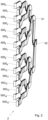
- THE figures 2 to 4 illustrate an example of a first divider-combiner 4 with the junctions 1-to-4 of the associated cell units, in the case of a dual polarization antenna comprising 16X16 antenna elements 3.
- the first divider/combiner is made up of several 2 blades juxtaposed, each blade being dedicated to one of the two LHCP or RHCP polarizations. As each antenna element provides two polarizations, the number of blades is therefore equal to twice the number of antenna elements per line, that is to say 32 blades in this example.
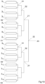
- Each blade 2 is intended to be connected to all of the antenna elements 3 of a column, that is to say to four cell units 8 superimposed in this example. It therefore comprises branches 500 0 to 500 15 , each of these branches being directly connected to one of the two output ports of one of the antennas.
- Two levels of 1-to-2 junctions in the H plane form a 1-to-4 junction (reference 5) allowing the signals to be combined/divided within each cell unit 8; the signal common to the trunk 501 of the junctions of the blade 2 is combined using two additional levels of junctions 1-to-2 in the plane H, the signal resulting from the addition of the signals in all the branches 500 of a blade 2 thus finding itself at the trunk 23 of this blade.
- FIG. 2 illustrates a single blade 2.
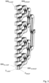
- the Figure 3 shows two juxtaposed blades, one being dedicated to a first LHCP polarization of several superimposed cell units and the other to the second polarization RHCP of the same cell units.
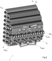
- FIG 4 illustrates the juxtaposition of 32 blades 2 constituting the first network of dividers/combiners of the antenna.
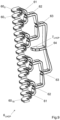
- FIG. 5 illustrates a 1-to-4-5 junction present in each cell unit.
- the junction therefore comprises four branches 500 intended to be connected to four ports of the antenna elements 3 of a cell unit 8.
- the first level includes two junctions 1-to-2 51 for combining/dividing the signals in two by two. same polarization of two superimposed antenna elements. The two antennas of each pair being out of phase, the junction is made in the H plane.
- a second 1-to-2 junction 50 then makes it possible to combine together the trunks of the two junctions 51, united in a common trunk 501.
- THE figures 6 and 7 illustrate an example of a 1-to-2 junction in more detail.
- This example relates to the first power divider/combiner 21 in the first network 4; however, the realization of the 1-to-2 junctions 50 and 51 in the cell units, and of the second power divider/combiner 22 in the first network 4 may be identical or similar, only the direction of the branches of the junction differing.
- the height b 1 of the trunk 201 is less than the height b 2 of the portion of the junction in which the signals combine or divide, this height b 2 itself being less than the total height b 3 of the two branches 200.
- FIG 8 illustrates the rear of the antenna 1, that is to say on the side opposite the front face from which the antenna elements 3 point.
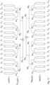
- a second network of dividers/combiners 6 in the plane E is intended to combine/divide the signals from the different blades 2, independently for each polarization.
- This network 6 comprises a first LHCP half-network 6 for the first LHCP polarization and whose branches form a first comb intended to be connected to the blades 2 of first polarization.
- a second half-array 6 RHCP for the second polarization RHCP comprises branches forming a second comb interposed between the first comb and intended to be connected to the blades 2 of second polarization.
- the trunk of the first half-array forms the first LHCP port 7 of antenna 1 and the trunk of the first half-array forms the first RHCP port 7.
- FIG. 9 illustrates one of the half-networks, for example the first half-network 6 LHCP .
- it comprises 16 branches 60 0 to 60 15 forming the comb intended to connect to the trunk/port of the different blades 2.
- the number of branches 60 depends of course on the number of blades 2.
- Four levels of junctions 1 -à-2 61,62,63,64 in the plane E successively allow the signals of these different branches to be combined/divided into a common trunk 7 forming one of the two ports of the antenna.
- the output of this trunk 7 is bent at 90° to facilitate connection to a waveguide or directly to the electronic circuit.
- FIG. 10 schematically illustrates the tree structure of the junctions within each blade 2, the blade grouping together both the first divider/combiner network 4 and the 1-to-4 junctions 5 of the cell units 8 associated with this blade.
- FIG. 11 schematically illustrates the tree structure of the junctions within the second network of dividers/combiners 6.
- the antenna is advantageously produced in a monolithic manner, preferably by 3D printing of a metal or polymer core, then deposition of a conductive layer at least on the internal faces of the waveguides of the antenna.
- the example above relates to an antenna comprising 16X16 antenna elements.
- This number is non-limiting and the number of antenna elements can be any.
- the number of lines is, however, preferably a multiple of 4 so that the antenna can be designed by stacking cell units comprising four antenna elements each.
- This number is also advantageously a power of two so as to be able to produce a first network of dividers/combiners 4 with an equal number of junctions between each branch of this network and the trunk of the blade, thus more easily guaranteeing paths of isophase length to the different branches.
- the number of antenna elements per branch, and therefore of blades 2 can be any. This number is, however, advantageously a power of two, so as to be able to produce a second network of dividers/combiners 6 with an equal number of junctions between each branch of this network and the ports 7 of the antenna, thus more easily guaranteeing paths of isophase length up to the different branches.
- the antenna may include a mounting hole passing through the network of dividers in a direction perpendicular to the direction of signal transmission, and allowing it to be mounted by threading it around a cylindrical mounting bar. This solution makes it possible to easily adjust the orientation of the antenna by pivoting it around the bar.
Landscapes
- Physics & Mathematics (AREA)
- Engineering & Computer Science (AREA)
- Astronomy & Astrophysics (AREA)
- General Physics & Mathematics (AREA)
- Remote Sensing (AREA)
- Aviation & Aerospace Engineering (AREA)
- Variable-Direction Aerials And Aerial Arrays (AREA)
- Waveguide Aerials (AREA)
Claims (14)
- Antenne (1) mit doppelter Polarisation (RHCP, LHCP), umfassend:mindestens einen ersten Anschluss (7), welcher dazu bestimmt ist, die Antenne mit einem aktiven Schaltkreis zum Übertragen oder Aussenden eines Signals mit einer ersten Polarisation (LHCP) zu verbinden;mindestens einen zweiten Anschluss (7), welcher dazu bestimmt ist, die Antenne mit einem oder mehreren aktiven Schaltkreisen zum Übertragen oder Aussenden eines Signals mit einer zweiten Polarisation (RHCP) zu verbinden;eine Vielzahl von dualpolarisierten Antennenelementen (3),wobei die Antennenelemente in Zelleinheiten (8) angeordnet sind,wobei jede Zelleinheit (5) vier Antennenelemente (3) und zwei 1-zu-4 Übergänge (5) umfasst, wobei einer der beiden Übergänge (5) einer ersten Polarisation und ein zweiter dieser beiden Übergänge einer zweiten Polarisation zugeordnet ist, wobei jeder besagter Übergang (5) vier Zweige (500) umfasst, um ihn jeweils mit einer der Polarisationen jedes Antennenelements (3) der entsprechenden Einheit zu verbinden, sowie einen gemeinsamen Stamm (501),ein Netzwerk von Teilern/Kombinierern (4, 6), um den Stamm (501) jedes besagten 1-zu-4-Übergangs (5) einer der ersten Polarisation zugeordneten Zelleneinheit (8) mit dem ersten Anschluss (7) zu verbinden, und um den Stamm (501) jedes besagten, der zweiten Polarisation zugeordneten 1-zu-4-Übergangs (5) mit dem zweiten Anschluss (7) zu verbinden,wobei die vier Antennenelemente (3) jeder Zelleinheit (8) übereinander angeordnet sind, wobei mehrere Zelleinheiten (8) nebeneinander angeordnet sind,dadurch gekennzeichnet, dass jede Zelleinheit (8) zwei Antennenelemente (3) in einer ersten Ebene und zwei weitere Antennenelemente (3) in einer zweiten Ebene parallel zur ersten Ebene umfasst, wobei die besagten Ebenen in Bezug auf einander in einer Richtung senkrecht zu den besagten Ebenen um einen Abstand, der kleiner als eine Breite eines Antennenelements ist, versetzt sind.
- Antenne gemäss Anspruch 1, wobei das besagte Netzwerk von Teilern/ Kombinierern (4, 6) ein erstes Unternetzwerk von Teilern/Kombinierern (4) umfasst, welches aus einem Stapel nebeneinander angeordneter Lamellen (2) besteht und derart angeordnet ist, um die Stämme (501) jedes der besagten 1-zu-4-Übergänge (5) aus mehreren übereinander angeordneten, der ersten Polarisation zugeordneten Zelleinheiten (8) miteinander zu verbinden, und um die Stämme (501) jedes der besagten 1-zu-4-Übergänge (5) aus mehrerer übereinander angeordneten, der zweiten Polarisation zugeordneten Zelleinheiten (8) miteinander zu verbinden.
- Antenne gemäss Anspruch 2, wobei das erste Unternetzwerk von Teilern/ Kombinierern (4) eine Abwechslung von ersten Lamellen (2LHCP), welche der ersten Polarisation zugeordnet sind, und zweiten Lamellen (2RHCP), welche der zweiten Polarisation zugeordnet sind, aufweist.
- Antenne gemäss Anspruch 3, mit einem zweiten Unternetzwerk aus Teilern/ Kombinierern (6), welche derart angeordnet sind, um die ersten Lamellen (2LHCP) miteinander und mit dem ersten Anschluss (7LHCP) zu verbinden, und um die zweiten Lamellen (2RHCP) miteinander und mit dem zweiten Anschluss (7RHCP) zu verbinden.
- Antenne gemäss einem der Ansprüche 2 bis 4, wobei sich jede Lamelle (2) in einer ersten Richtung, die im Wesentlichen senkrecht zu einer Signalübertragungsrichtung verläuft, und zwischen den beiden Ebenen, die durch äusserste Seitenkanten der diesem Blatt zugeordneten Antennenelemente definiert sind, erstreckt.
- Antenne gemäss einem der Ansprüche 3 bis 4, wobei sich eine besagte erste Lamelle (2LHCP) und eine besagte zweite Lamelle (2RHCP) zwischen den beiden Ebenen, die durch äusserste Seitenkanten der diesen beiden Lamellen zugeordneten Antennenelemente definiert sind, erstrecken.
- Antenne gemäss einem der Ansprüche 4 bis 6, wobei das zweite Unternetzwerk (6) zwischen den besagten Lamellen (2) und den besagten Anschlüssen vorgesehen ist und Wellenleiterabschnitte umfasst, welche sich in einer zweiten Richtung im Wesentlichen senkrecht zu einer Signalübertragungsrichtung erstrecken.
- Antenne gemäss einem der Ansprüche 2 bis 7, wobei jede Lamelle (2) vier Zelleneinheiten (8) zugeordnet ist.
- Antenne gemäss einem der Ansprüche 3 bis 8, bestehend aus 32 besagten Lamellen.
- Antenne gemäss einem der Ansprüche 1 bis 9, wobei jedes Antennenelement (3) eine Trennwand (32) umfasst, um die beiden Polarisationen eines Hochfrequenzsignals beim Senden zu kombinieren oder beim Empfang zu trennen.
- Antenne gemäss Anspruch 10, wobei jedes Antennenelement (3) mit zwei benachbarten Lamellen (2LHCP, 2RHCP) verbunden ist.
- Antenne gemäss einem der Ansprüche 1 bis 11, wobei jedes Antennenelement (3) einen Querschnitt senkrecht zu einer Ausbreitungsrichtung des quadratischen Signals aufweist.
- Antenne gemäss einem der Ansprüche 1 bis 12, welche mindestens eine zylindrische Öffnung in einer Richtung senkrecht zu einer Signalübertragungsrichtung aufweist und welche dazu bestimmt ist, die Antenne an einem Stab zu befestigen, der es ermöglicht, sie zu halten und auszurichten.
- Antenne gemäss einem der Ansprüche 1 bis 13, mit einem im 3D-Druck hergestellten Kern und einer Oberflächenschicht auf zumindest einer Innenseite dieses Kerns.
Applications Claiming Priority (2)
| Application Number | Priority Date | Filing Date | Title |
|---|---|---|---|
| FR1914809A FR3105611B1 (fr) | 2019-12-18 | 2019-12-18 | Antenne à double polarisation |
| PCT/IB2020/062059 WO2021124170A1 (fr) | 2019-12-18 | 2020-12-16 | Antenne à double polarisation |
Publications (2)
| Publication Number | Publication Date |
|---|---|
| EP4078728A1 EP4078728A1 (de) | 2022-10-26 |
| EP4078728B1 true EP4078728B1 (de) | 2024-07-31 |
Family
ID=70613946
Family Applications (1)
| Application Number | Title | Priority Date | Filing Date |
|---|---|---|---|
| EP20824690.0A Active EP4078728B1 (de) | 2019-12-18 | 2020-12-16 | Doppelpolarisationsantenne |
Country Status (8)
| Country | Link |
|---|---|
| US (1) | US20230011966A1 (de) |
| EP (1) | EP4078728B1 (de) |
| CA (1) | CA3157973A1 (de) |
| ES (1) | ES2994262T3 (de) |
| FR (1) | FR3105611B1 (de) |
| IL (1) | IL293345A (de) |
| PL (1) | PL4078728T3 (de) |
| WO (1) | WO2021124170A1 (de) |
Families Citing this family (3)
| Publication number | Priority date | Publication date | Assignee | Title |
|---|---|---|---|---|
| WO2022155989A1 (zh) * | 2021-01-20 | 2022-07-28 | 佛山市三水瑞莱尔通讯设备有限公司 | 天线及组合天线 |
| DE102022209120A1 (de) * | 2022-09-02 | 2024-03-07 | Robert Bosch Gesellschaft mit beschränkter Haftung | Radarsensor mit Hohlleiterstruktur |
| IL322771A (en) * | 2023-03-13 | 2025-10-01 | Swissto12 Sa | Waveguide array with a rounded cross-section |
Family Cites Families (6)
| Publication number | Priority date | Publication date | Assignee | Title |
|---|---|---|---|---|
| CN102414922B (zh) * | 2009-04-30 | 2014-10-01 | Qest量子电子系统有限公司 | 用于卫星通信的宽带天线系统 |
| KR20130066906A (ko) * | 2011-12-13 | 2013-06-21 | 주식회사 마이크로페이스 | 간단한 도파관 급전망과, 이의 평판형 도파관 안테나 |
| EP3114732B1 (de) * | 2014-03-06 | 2020-08-26 | ViaSat, Inc. | Wellenleiterspeisenetzarchitektur für breitbandige duale polarisierte planare horngruppenantennen |
| US9559428B1 (en) * | 2015-08-25 | 2017-01-31 | Viasat, Inc. | Compact waveguide power combiner/divider for dual-polarized antenna elements |
| US20170237182A1 (en) * | 2015-09-21 | 2017-08-17 | Qualcomm Incorporated | Antenna with beamwidth reconfigurable circularly polarized radiators |
| US11784384B2 (en) * | 2017-12-20 | 2023-10-10 | Optisys, LLC | Integrated tracking antenna array combiner network |
-
2019
- 2019-12-18 FR FR1914809A patent/FR3105611B1/fr active Active
-
2020
- 2020-12-16 US US17/757,319 patent/US20230011966A1/en active Pending
- 2020-12-16 PL PL20824690.0T patent/PL4078728T3/pl unknown
- 2020-12-16 WO PCT/IB2020/062059 patent/WO2021124170A1/fr not_active Ceased
- 2020-12-16 CA CA3157973A patent/CA3157973A1/en active Pending
- 2020-12-16 ES ES20824690T patent/ES2994262T3/es active Active
- 2020-12-16 EP EP20824690.0A patent/EP4078728B1/de active Active
- 2020-12-16 IL IL293345A patent/IL293345A/en unknown
Also Published As
| Publication number | Publication date |
|---|---|
| FR3105611B1 (fr) | 2023-01-06 |
| EP4078728A1 (de) | 2022-10-26 |
| ES2994262T3 (en) | 2025-01-20 |
| WO2021124170A1 (fr) | 2021-06-24 |
| IL293345A (en) | 2022-07-01 |
| US20230011966A1 (en) | 2023-01-12 |
| PL4078728T3 (pl) | 2025-02-24 |
| FR3105611A1 (fr) | 2021-06-25 |
| CA3157973A1 (en) | 2021-06-24 |
Similar Documents
| Publication | Publication Date | Title |
|---|---|---|
| EP0372451B1 (de) | Multifrequenz-Strahlungsvorrichtung | |
| EP2869400B1 (de) | Doppelpolarisierter kompakter Leistungsverteiler, Netz aus mehreren Verteilern, kompaktes Strahlungselement und Flachantenne, die einen solchen Verteiler umfasst | |
| EP2664030B1 (de) | Gedruckte schlitzrichtantenne und system mit einer gruppe aus bedruckten schlitzrichtantennen | |
| EP3824511B1 (de) | Hochfrequenzkomponenten mit mehreren wellenleitervorrichtungen mit rippen | |
| EP4078728B1 (de) | Doppelpolarisationsantenne | |
| EP2194602B1 (de) | Antenne mit gemeinsam benützten Elementarstrahlern und Verfahren zum Entwurf einer Mehrstrahlantenne mit gemeinsam benützten Elementarstrahlern | |
| EP3073569B1 (de) | Butler matrix compact, bi-dimensionales planare beam-former und planarantenne mit einer solchen butler matrix | |
| EP3179551B1 (de) | Kompakteinheit zur doppelpolarisierten ansteuerung für ein strahlungselement einer antenne, und kompaktes netz, das mindestens vier kompakte ansteuerungseinheiten umfasst | |
| CA2821242C (fr) | Antenne et systeme d'antennes multifaisceaux comportant des sources compactes et systeme de telecommunication par satellite comportant au moins une telle antenne | |
| EP2688142B1 (de) | Mehrfachstrahl-Sende- und Empfangsantenne mit mehreren Quellen pro Strahl, Antennensystem und Satellitentelekommunikationssystem, die eine solche Antenne umfassen | |
| FR3035548A1 (fr) | Architecture d'antenne a plusieurs sources par faisceau et comportant un reseau focal modulaire | |
| EP1690317A1 (de) | Doppeltpolarisierte mehrband-gruppenantenne | |
| FR3044832A1 (fr) | Architecture d'antenne active a formation de faisceaux hybride reconfigurable | |
| FR3035546A1 (fr) | Module structural d'antenne integrant des sources rayonnantes elementaires a orientation individuelle, panneau rayonnant, reseau rayonnant et antenne multifaisceaux comportant au moins un tel module | |
| EP2434578B1 (de) | Antennensystem mit zwei Spot-Gittern mit komplementären überlappten Netzen | |
| EP3462532B1 (de) | Leistungsverteiler für antenne, der vier identische orthomode transducer umfasst | |
| FR2904478A1 (fr) | Dispositif de transduction orthomode a compacite optimisee dans le plan de maille, pour une antenne | |
| EP3664214B1 (de) | Mehrfachzugriff strahlelemente | |
| EP4092831A1 (de) | Antenne mit lückenhaftem verteilungsnetz | |
| EP3900113B1 (de) | Elementare mikrostreifenantenne und gruppenantenne | |
| EP2637254B1 (de) | Flachantenne für Endgerät, das über eine doppelte Kreispolarisierung funktioniert, auf dem Luftweg transportiertes Endgerät und Satellitentelekommunikationssystem, das mindestens eine solche Antenne umfasst | |
| EP4616480A1 (de) | Doppelpolarisationsantenne mit steg | |
| FR3156600A1 (fr) | Antenne réseau améliorée du type comportant une pluralité d’éléments rayonnants planaires alimentés en série |
Legal Events
| Date | Code | Title | Description |
|---|---|---|---|
| STAA | Information on the status of an ep patent application or granted ep patent |
Free format text: STATUS: UNKNOWN |
|
| STAA | Information on the status of an ep patent application or granted ep patent |
Free format text: STATUS: THE INTERNATIONAL PUBLICATION HAS BEEN MADE |
|
| PUAI | Public reference made under article 153(3) epc to a published international application that has entered the european phase |
Free format text: ORIGINAL CODE: 0009012 |
|
| STAA | Information on the status of an ep patent application or granted ep patent |
Free format text: STATUS: REQUEST FOR EXAMINATION WAS MADE |
|
| 17P | Request for examination filed |
Effective date: 20220616 |
|
| AK | Designated contracting states |
Kind code of ref document: A1 Designated state(s): AL AT BE BG CH CY CZ DE DK EE ES FI FR GB GR HR HU IE IS IT LI LT LU LV MC MK MT NL NO PL PT RO RS SE SI SK SM TR |
|
| DAV | Request for validation of the european patent (deleted) | ||
| DAX | Request for extension of the european patent (deleted) | ||
| GRAP | Despatch of communication of intention to grant a patent |
Free format text: ORIGINAL CODE: EPIDOSNIGR1 |
|
| STAA | Information on the status of an ep patent application or granted ep patent |
Free format text: STATUS: GRANT OF PATENT IS INTENDED |
|
| INTG | Intention to grant announced |
Effective date: 20230531 |
|
| STAA | Information on the status of an ep patent application or granted ep patent |
Free format text: STATUS: THE APPLICATION IS DEEMED TO BE WITHDRAWN |
|
| 18D | Application deemed to be withdrawn |
Effective date: 20231011 |
|
| 18RA | Request filed for re-establishment of rights before grant |
Effective date: 20240508 |
|
| GRAS | Grant fee paid |
Free format text: ORIGINAL CODE: EPIDOSNIGR3 |
|
| STAA | Information on the status of an ep patent application or granted ep patent |
Free format text: STATUS: GRANT OF PATENT IS INTENDED |
|
| GRAA | (expected) grant |
Free format text: ORIGINAL CODE: 0009210 |
|
| STAA | Information on the status of an ep patent application or granted ep patent |
Free format text: STATUS: THE PATENT HAS BEEN GRANTED |
|
| D18D | Application deemed to be withdrawn (deleted) | ||
| AK | Designated contracting states |
Kind code of ref document: B1 Designated state(s): AL AT BE BG CH CY CZ DE DK EE ES FI FR GB GR HR HU IE IS IT LI LT LU LV MC MK MT NL NO PL PT RO RS SE SI SK SM TR |
|
| REG | Reference to a national code |
Ref country code: CH Ref legal event code: EP |
|
| REG | Reference to a national code |
Ref country code: DE Ref legal event code: R096 Ref document number: 602020034994 Country of ref document: DE |
|
| REG | Reference to a national code |
Ref country code: IE Ref legal event code: FG4D Free format text: LANGUAGE OF EP DOCUMENT: FRENCH |
|
| REG | Reference to a national code |
Ref country code: NL Ref legal event code: FP |
|
| REG | Reference to a national code |
Ref country code: SE Ref legal event code: TRGR |
|
| REG | Reference to a national code |
Ref country code: LT Ref legal event code: MG9D |
|
| PG25 | Lapsed in a contracting state [announced via postgrant information from national office to epo] |
Ref country code: PT Free format text: LAPSE BECAUSE OF FAILURE TO SUBMIT A TRANSLATION OF THE DESCRIPTION OR TO PAY THE FEE WITHIN THE PRESCRIBED TIME-LIMIT Effective date: 20241202 |
|
| REG | Reference to a national code |
Ref country code: AT Ref legal event code: MK05 Ref document number: 1709387 Country of ref document: AT Kind code of ref document: T Effective date: 20240731 |
|
| PG25 | Lapsed in a contracting state [announced via postgrant information from national office to epo] |
Ref country code: PT Free format text: LAPSE BECAUSE OF FAILURE TO SUBMIT A TRANSLATION OF THE DESCRIPTION OR TO PAY THE FEE WITHIN THE PRESCRIBED TIME-LIMIT Effective date: 20241202 |
|
| PGFP | Annual fee paid to national office [announced via postgrant information from national office to epo] |
Ref country code: NO Payment date: 20241227 Year of fee payment: 5 |
|
| PG25 | Lapsed in a contracting state [announced via postgrant information from national office to epo] |
Ref country code: FI Free format text: LAPSE BECAUSE OF FAILURE TO SUBMIT A TRANSLATION OF THE DESCRIPTION OR TO PAY THE FEE WITHIN THE PRESCRIBED TIME-LIMIT Effective date: 20240731 Ref country code: GR Free format text: LAPSE BECAUSE OF FAILURE TO SUBMIT A TRANSLATION OF THE DESCRIPTION OR TO PAY THE FEE WITHIN THE PRESCRIBED TIME-LIMIT Effective date: 20241101 |
|
| PG25 | Lapsed in a contracting state [announced via postgrant information from national office to epo] |
Ref country code: BG Free format text: LAPSE BECAUSE OF FAILURE TO SUBMIT A TRANSLATION OF THE DESCRIPTION OR TO PAY THE FEE WITHIN THE PRESCRIBED TIME-LIMIT Effective date: 20240731 |
|
| REG | Reference to a national code |
Ref country code: ES Ref legal event code: FG2A Ref document number: 2994262 Country of ref document: ES Kind code of ref document: T3 Effective date: 20250120 |
|
| PG25 | Lapsed in a contracting state [announced via postgrant information from national office to epo] |
Ref country code: LV Free format text: LAPSE BECAUSE OF FAILURE TO SUBMIT A TRANSLATION OF THE DESCRIPTION OR TO PAY THE FEE WITHIN THE PRESCRIBED TIME-LIMIT Effective date: 20240731 |
|
| PG25 | Lapsed in a contracting state [announced via postgrant information from national office to epo] |
Ref country code: AT Free format text: LAPSE BECAUSE OF FAILURE TO SUBMIT A TRANSLATION OF THE DESCRIPTION OR TO PAY THE FEE WITHIN THE PRESCRIBED TIME-LIMIT Effective date: 20240731 Ref country code: IS Free format text: LAPSE BECAUSE OF FAILURE TO SUBMIT A TRANSLATION OF THE DESCRIPTION OR TO PAY THE FEE WITHIN THE PRESCRIBED TIME-LIMIT Effective date: 20241130 |
|
| PG25 | Lapsed in a contracting state [announced via postgrant information from national office to epo] |
Ref country code: HR Free format text: LAPSE BECAUSE OF FAILURE TO SUBMIT A TRANSLATION OF THE DESCRIPTION OR TO PAY THE FEE WITHIN THE PRESCRIBED TIME-LIMIT Effective date: 20240731 |
|
| PG25 | Lapsed in a contracting state [announced via postgrant information from national office to epo] |
Ref country code: RS Free format text: LAPSE BECAUSE OF FAILURE TO SUBMIT A TRANSLATION OF THE DESCRIPTION OR TO PAY THE FEE WITHIN THE PRESCRIBED TIME-LIMIT Effective date: 20241031 |
|
| PG25 | Lapsed in a contracting state [announced via postgrant information from national office to epo] |
Ref country code: RS Free format text: LAPSE BECAUSE OF FAILURE TO SUBMIT A TRANSLATION OF THE DESCRIPTION OR TO PAY THE FEE WITHIN THE PRESCRIBED TIME-LIMIT Effective date: 20241031 Ref country code: LV Free format text: LAPSE BECAUSE OF FAILURE TO SUBMIT A TRANSLATION OF THE DESCRIPTION OR TO PAY THE FEE WITHIN THE PRESCRIBED TIME-LIMIT Effective date: 20240731 Ref country code: IS Free format text: LAPSE BECAUSE OF FAILURE TO SUBMIT A TRANSLATION OF THE DESCRIPTION OR TO PAY THE FEE WITHIN THE PRESCRIBED TIME-LIMIT Effective date: 20241130 Ref country code: HR Free format text: LAPSE BECAUSE OF FAILURE TO SUBMIT A TRANSLATION OF THE DESCRIPTION OR TO PAY THE FEE WITHIN THE PRESCRIBED TIME-LIMIT Effective date: 20240731 Ref country code: GR Free format text: LAPSE BECAUSE OF FAILURE TO SUBMIT A TRANSLATION OF THE DESCRIPTION OR TO PAY THE FEE WITHIN THE PRESCRIBED TIME-LIMIT Effective date: 20241101 Ref country code: FI Free format text: LAPSE BECAUSE OF FAILURE TO SUBMIT A TRANSLATION OF THE DESCRIPTION OR TO PAY THE FEE WITHIN THE PRESCRIBED TIME-LIMIT Effective date: 20240731 Ref country code: BG Free format text: LAPSE BECAUSE OF FAILURE TO SUBMIT A TRANSLATION OF THE DESCRIPTION OR TO PAY THE FEE WITHIN THE PRESCRIBED TIME-LIMIT Effective date: 20240731 Ref country code: AT Free format text: LAPSE BECAUSE OF FAILURE TO SUBMIT A TRANSLATION OF THE DESCRIPTION OR TO PAY THE FEE WITHIN THE PRESCRIBED TIME-LIMIT Effective date: 20240731 |
|
| PG25 | Lapsed in a contracting state [announced via postgrant information from national office to epo] |
Ref country code: DK Free format text: LAPSE BECAUSE OF FAILURE TO SUBMIT A TRANSLATION OF THE DESCRIPTION OR TO PAY THE FEE WITHIN THE PRESCRIBED TIME-LIMIT Effective date: 20240731 Ref country code: SM Free format text: LAPSE BECAUSE OF FAILURE TO SUBMIT A TRANSLATION OF THE DESCRIPTION OR TO PAY THE FEE WITHIN THE PRESCRIBED TIME-LIMIT Effective date: 20240731 Ref country code: RO Free format text: LAPSE BECAUSE OF FAILURE TO SUBMIT A TRANSLATION OF THE DESCRIPTION OR TO PAY THE FEE WITHIN THE PRESCRIBED TIME-LIMIT Effective date: 20240731 |
|
| PGFP | Annual fee paid to national office [announced via postgrant information from national office to epo] |
Ref country code: ES Payment date: 20250131 Year of fee payment: 5 |
|
| PG25 | Lapsed in a contracting state [announced via postgrant information from national office to epo] |
Ref country code: EE Free format text: LAPSE BECAUSE OF FAILURE TO SUBMIT A TRANSLATION OF THE DESCRIPTION OR TO PAY THE FEE WITHIN THE PRESCRIBED TIME-LIMIT Effective date: 20240731 |
|
| PGFP | Annual fee paid to national office [announced via postgrant information from national office to epo] |
Ref country code: CH Payment date: 20250101 Year of fee payment: 5 |
|
| PG25 | Lapsed in a contracting state [announced via postgrant information from national office to epo] |
Ref country code: CZ Free format text: LAPSE BECAUSE OF FAILURE TO SUBMIT A TRANSLATION OF THE DESCRIPTION OR TO PAY THE FEE WITHIN THE PRESCRIBED TIME-LIMIT Effective date: 20240731 |
|
| PG25 | Lapsed in a contracting state [announced via postgrant information from national office to epo] |
Ref country code: SK Free format text: LAPSE BECAUSE OF FAILURE TO SUBMIT A TRANSLATION OF THE DESCRIPTION OR TO PAY THE FEE WITHIN THE PRESCRIBED TIME-LIMIT Effective date: 20240731 |
|
| REG | Reference to a national code |
Ref country code: DE Ref legal event code: R097 Ref document number: 602020034994 Country of ref document: DE |
|
| PLBE | No opposition filed within time limit |
Free format text: ORIGINAL CODE: 0009261 |
|
| STAA | Information on the status of an ep patent application or granted ep patent |
Free format text: STATUS: NO OPPOSITION FILED WITHIN TIME LIMIT |
|
| PG25 | Lapsed in a contracting state [announced via postgrant information from national office to epo] |
Ref country code: MC Free format text: LAPSE BECAUSE OF FAILURE TO SUBMIT A TRANSLATION OF THE DESCRIPTION OR TO PAY THE FEE WITHIN THE PRESCRIBED TIME-LIMIT Effective date: 20240731 |
|
| 26N | No opposition filed |
Effective date: 20250501 |
|
| PG25 | Lapsed in a contracting state [announced via postgrant information from national office to epo] |
Ref country code: IE Free format text: LAPSE BECAUSE OF NON-PAYMENT OF DUE FEES Effective date: 20241216 |
|
| REG | Reference to a national code |
Ref country code: CH Ref legal event code: U11 Free format text: ST27 STATUS EVENT CODE: U-0-0-U10-U11 (AS PROVIDED BY THE NATIONAL OFFICE) Effective date: 20260101 |
|
| PGFP | Annual fee paid to national office [announced via postgrant information from national office to epo] |
Ref country code: DE Payment date: 20251211 Year of fee payment: 6 |
|
| PGFP | Annual fee paid to national office [announced via postgrant information from national office to epo] |
Ref country code: GB Payment date: 20251219 Year of fee payment: 6 |
|
| PGFP | Annual fee paid to national office [announced via postgrant information from national office to epo] |
Ref country code: IT Payment date: 20251223 Year of fee payment: 6 |
|
| PGFP | Annual fee paid to national office [announced via postgrant information from national office to epo] |
Ref country code: LU Payment date: 20251219 Year of fee payment: 6 Ref country code: NL Payment date: 20251219 Year of fee payment: 6 Ref country code: FR Payment date: 20251229 Year of fee payment: 6 |
|
| PGFP | Annual fee paid to national office [announced via postgrant information from national office to epo] |
Ref country code: BE Payment date: 20251219 Year of fee payment: 6 |
|
| PGFP | Annual fee paid to national office [announced via postgrant information from national office to epo] |
Ref country code: SE Payment date: 20251219 Year of fee payment: 6 |
|
| PGFP | Annual fee paid to national office [announced via postgrant information from national office to epo] |
Ref country code: PL Payment date: 20251119 Year of fee payment: 6 |