EP4078014B1 - Verfahren zur schätzung und einstellung einer energiebilanz eines in einem tank enthaltenen gases in flüssiger form - Google Patents
Verfahren zur schätzung und einstellung einer energiebilanz eines in einem tank enthaltenen gases in flüssiger form Download PDFInfo
- Publication number
- EP4078014B1 EP4078014B1 EP20848857.7A EP20848857A EP4078014B1 EP 4078014 B1 EP4078014 B1 EP 4078014B1 EP 20848857 A EP20848857 A EP 20848857A EP 4078014 B1 EP4078014 B1 EP 4078014B1
- Authority
- EP
- European Patent Office
- Prior art keywords
- gas
- liquid form
- energy balance
- tank
- floating structure
- Prior art date
- Legal status (The legal status is an assumption and is not a legal conclusion. Google has not performed a legal analysis and makes no representation as to the accuracy of the status listed.)
- Active
Links
Images


Classifications
-
- B—PERFORMING OPERATIONS; TRANSPORTING
- B63—SHIPS OR OTHER WATERBORNE VESSELS; RELATED EQUIPMENT
- B63B—SHIPS OR OTHER WATERBORNE VESSELS; EQUIPMENT FOR SHIPPING
- B63B25/00—Load-accommodating arrangements, e.g. stowing, trimming; Vessels characterised thereby
- B63B25/02—Load-accommodating arrangements, e.g. stowing, trimming; Vessels characterised thereby for bulk goods
- B63B25/08—Load-accommodating arrangements, e.g. stowing, trimming; Vessels characterised thereby for bulk goods fluid
- B63B25/12—Load-accommodating arrangements, e.g. stowing, trimming; Vessels characterised thereby for bulk goods fluid closed
- B63B25/16—Load-accommodating arrangements, e.g. stowing, trimming; Vessels characterised thereby for bulk goods fluid closed heat-insulated
-
- B—PERFORMING OPERATIONS; TRANSPORTING
- B63—SHIPS OR OTHER WATERBORNE VESSELS; RELATED EQUIPMENT
- B63B—SHIPS OR OTHER WATERBORNE VESSELS; EQUIPMENT FOR SHIPPING
- B63B79/00—Monitoring properties or operating parameters of vessels in operation
- B63B79/30—Monitoring properties or operating parameters of vessels in operation for diagnosing, testing or predicting the integrity or performance of vessels
-
- F—MECHANICAL ENGINEERING; LIGHTING; HEATING; WEAPONS; BLASTING
- F17—STORING OR DISTRIBUTING GASES OR LIQUIDS
- F17C—VESSELS FOR CONTAINING OR STORING COMPRESSED, LIQUEFIED OR SOLIDIFIED GASES; FIXED-CAPACITY GAS-HOLDERS; FILLING VESSELS WITH, OR DISCHARGING FROM VESSELS, COMPRESSED, LIQUEFIED, OR SOLIDIFIED GASES
- F17C13/00—Details of vessels or of the filling or discharging of vessels
- F17C13/004—Details of vessels or of the filling or discharging of vessels for large storage vessels not under pressure
-
- F—MECHANICAL ENGINEERING; LIGHTING; HEATING; WEAPONS; BLASTING
- F17—STORING OR DISTRIBUTING GASES OR LIQUIDS
- F17C—VESSELS FOR CONTAINING OR STORING COMPRESSED, LIQUEFIED OR SOLIDIFIED GASES; FIXED-CAPACITY GAS-HOLDERS; FILLING VESSELS WITH, OR DISCHARGING FROM VESSELS, COMPRESSED, LIQUEFIED, OR SOLIDIFIED GASES
- F17C13/00—Details of vessels or of the filling or discharging of vessels
- F17C13/02—Special adaptations of indicating, measuring, or monitoring equipment
-
- F—MECHANICAL ENGINEERING; LIGHTING; HEATING; WEAPONS; BLASTING
- F17—STORING OR DISTRIBUTING GASES OR LIQUIDS
- F17C—VESSELS FOR CONTAINING OR STORING COMPRESSED, LIQUEFIED OR SOLIDIFIED GASES; FIXED-CAPACITY GAS-HOLDERS; FILLING VESSELS WITH, OR DISCHARGING FROM VESSELS, COMPRESSED, LIQUEFIED, OR SOLIDIFIED GASES
- F17C2201/00—Vessel construction, in particular geometry, arrangement or size
- F17C2201/05—Size
- F17C2201/052—Size large (>1000 m3)
-
- F—MECHANICAL ENGINEERING; LIGHTING; HEATING; WEAPONS; BLASTING
- F17—STORING OR DISTRIBUTING GASES OR LIQUIDS
- F17C—VESSELS FOR CONTAINING OR STORING COMPRESSED, LIQUEFIED OR SOLIDIFIED GASES; FIXED-CAPACITY GAS-HOLDERS; FILLING VESSELS WITH, OR DISCHARGING FROM VESSELS, COMPRESSED, LIQUEFIED, OR SOLIDIFIED GASES
- F17C2221/00—Handled fluid, in particular type of fluid
- F17C2221/03—Mixtures
- F17C2221/032—Hydrocarbons
- F17C2221/033—Methane, e.g. natural gas, CNG, LNG, GNL, GNC, PLNG
-
- F—MECHANICAL ENGINEERING; LIGHTING; HEATING; WEAPONS; BLASTING
- F17—STORING OR DISTRIBUTING GASES OR LIQUIDS
- F17C—VESSELS FOR CONTAINING OR STORING COMPRESSED, LIQUEFIED OR SOLIDIFIED GASES; FIXED-CAPACITY GAS-HOLDERS; FILLING VESSELS WITH, OR DISCHARGING FROM VESSELS, COMPRESSED, LIQUEFIED, OR SOLIDIFIED GASES
- F17C2223/00—Handled fluid before transfer, i.e. state of fluid when stored in the vessel or before transfer from the vessel
- F17C2223/01—Handled fluid before transfer, i.e. state of fluid when stored in the vessel or before transfer from the vessel characterised by the phase
- F17C2223/0146—Two-phase
- F17C2223/0153—Liquefied gas, e.g. LPG, GPL
- F17C2223/0161—Liquefied gas, e.g. LPG, GPL cryogenic, e.g. LNG, GNL, PLNG
-
- F—MECHANICAL ENGINEERING; LIGHTING; HEATING; WEAPONS; BLASTING
- F17—STORING OR DISTRIBUTING GASES OR LIQUIDS
- F17C—VESSELS FOR CONTAINING OR STORING COMPRESSED, LIQUEFIED OR SOLIDIFIED GASES; FIXED-CAPACITY GAS-HOLDERS; FILLING VESSELS WITH, OR DISCHARGING FROM VESSELS, COMPRESSED, LIQUEFIED, OR SOLIDIFIED GASES
- F17C2223/00—Handled fluid before transfer, i.e. state of fluid when stored in the vessel or before transfer from the vessel
- F17C2223/03—Handled fluid before transfer, i.e. state of fluid when stored in the vessel or before transfer from the vessel characterised by the pressure level
- F17C2223/033—Small pressure, e.g. for liquefied gas
-
- F—MECHANICAL ENGINEERING; LIGHTING; HEATING; WEAPONS; BLASTING
- F17—STORING OR DISTRIBUTING GASES OR LIQUIDS
- F17C—VESSELS FOR CONTAINING OR STORING COMPRESSED, LIQUEFIED OR SOLIDIFIED GASES; FIXED-CAPACITY GAS-HOLDERS; FILLING VESSELS WITH, OR DISCHARGING FROM VESSELS, COMPRESSED, LIQUEFIED, OR SOLIDIFIED GASES
- F17C2225/00—Handled fluid after transfer, i.e. state of fluid after transfer from the vessel
- F17C2225/04—Handled fluid after transfer, i.e. state of fluid after transfer from the vessel characterised by other properties of handled fluid after transfer
- F17C2225/042—Localisation of the filling point
- F17C2225/043—Localisation of the filling point in the gas
- F17C2225/044—Localisation of the filling point in the gas at several points, e.g. with a device for recondensing gas
-
- F—MECHANICAL ENGINEERING; LIGHTING; HEATING; WEAPONS; BLASTING
- F17—STORING OR DISTRIBUTING GASES OR LIQUIDS
- F17C—VESSELS FOR CONTAINING OR STORING COMPRESSED, LIQUEFIED OR SOLIDIFIED GASES; FIXED-CAPACITY GAS-HOLDERS; FILLING VESSELS WITH, OR DISCHARGING FROM VESSELS, COMPRESSED, LIQUEFIED, OR SOLIDIFIED GASES
- F17C2227/00—Transfer of fluids, i.e. method or means for transferring the fluid; Heat exchange with the fluid
- F17C2227/03—Heat exchange with the fluid
- F17C2227/0337—Heat exchange with the fluid by cooling
-
- F—MECHANICAL ENGINEERING; LIGHTING; HEATING; WEAPONS; BLASTING
- F17—STORING OR DISTRIBUTING GASES OR LIQUIDS
- F17C—VESSELS FOR CONTAINING OR STORING COMPRESSED, LIQUEFIED OR SOLIDIFIED GASES; FIXED-CAPACITY GAS-HOLDERS; FILLING VESSELS WITH, OR DISCHARGING FROM VESSELS, COMPRESSED, LIQUEFIED, OR SOLIDIFIED GASES
- F17C2250/00—Accessories; Control means; Indicating, measuring or monitoring of parameters
- F17C2250/03—Control means
- F17C2250/032—Control means using computers
-
- F—MECHANICAL ENGINEERING; LIGHTING; HEATING; WEAPONS; BLASTING
- F17—STORING OR DISTRIBUTING GASES OR LIQUIDS
- F17C—VESSELS FOR CONTAINING OR STORING COMPRESSED, LIQUEFIED OR SOLIDIFIED GASES; FIXED-CAPACITY GAS-HOLDERS; FILLING VESSELS WITH, OR DISCHARGING FROM VESSELS, COMPRESSED, LIQUEFIED, OR SOLIDIFIED GASES
- F17C2250/00—Accessories; Control means; Indicating, measuring or monitoring of parameters
- F17C2250/04—Indicating or measuring of parameters as input values
- F17C2250/0404—Parameters indicated or measured
- F17C2250/043—Pressure
-
- F—MECHANICAL ENGINEERING; LIGHTING; HEATING; WEAPONS; BLASTING
- F17—STORING OR DISTRIBUTING GASES OR LIQUIDS
- F17C—VESSELS FOR CONTAINING OR STORING COMPRESSED, LIQUEFIED OR SOLIDIFIED GASES; FIXED-CAPACITY GAS-HOLDERS; FILLING VESSELS WITH, OR DISCHARGING FROM VESSELS, COMPRESSED, LIQUEFIED, OR SOLIDIFIED GASES
- F17C2250/00—Accessories; Control means; Indicating, measuring or monitoring of parameters
- F17C2250/04—Indicating or measuring of parameters as input values
- F17C2250/0404—Parameters indicated or measured
- F17C2250/0439—Temperature
-
- F—MECHANICAL ENGINEERING; LIGHTING; HEATING; WEAPONS; BLASTING
- F17—STORING OR DISTRIBUTING GASES OR LIQUIDS
- F17C—VESSELS FOR CONTAINING OR STORING COMPRESSED, LIQUEFIED OR SOLIDIFIED GASES; FIXED-CAPACITY GAS-HOLDERS; FILLING VESSELS WITH, OR DISCHARGING FROM VESSELS, COMPRESSED, LIQUEFIED, OR SOLIDIFIED GASES
- F17C2250/00—Accessories; Control means; Indicating, measuring or monitoring of parameters
- F17C2250/04—Indicating or measuring of parameters as input values
- F17C2250/0404—Parameters indicated or measured
- F17C2250/0473—Time or time periods
-
- F—MECHANICAL ENGINEERING; LIGHTING; HEATING; WEAPONS; BLASTING
- F17—STORING OR DISTRIBUTING GASES OR LIQUIDS
- F17C—VESSELS FOR CONTAINING OR STORING COMPRESSED, LIQUEFIED OR SOLIDIFIED GASES; FIXED-CAPACITY GAS-HOLDERS; FILLING VESSELS WITH, OR DISCHARGING FROM VESSELS, COMPRESSED, LIQUEFIED, OR SOLIDIFIED GASES
- F17C2250/00—Accessories; Control means; Indicating, measuring or monitoring of parameters
- F17C2250/04—Indicating or measuring of parameters as input values
- F17C2250/0404—Parameters indicated or measured
- F17C2250/0478—Position or presence
-
- F—MECHANICAL ENGINEERING; LIGHTING; HEATING; WEAPONS; BLASTING
- F17—STORING OR DISTRIBUTING GASES OR LIQUIDS
- F17C—VESSELS FOR CONTAINING OR STORING COMPRESSED, LIQUEFIED OR SOLIDIFIED GASES; FIXED-CAPACITY GAS-HOLDERS; FILLING VESSELS WITH, OR DISCHARGING FROM VESSELS, COMPRESSED, LIQUEFIED, OR SOLIDIFIED GASES
- F17C2250/00—Accessories; Control means; Indicating, measuring or monitoring of parameters
- F17C2250/06—Controlling or regulating of parameters as output values
- F17C2250/0689—Methods for controlling or regulating
- F17C2250/0694—Methods for controlling or regulating with calculations
-
- F—MECHANICAL ENGINEERING; LIGHTING; HEATING; WEAPONS; BLASTING
- F17—STORING OR DISTRIBUTING GASES OR LIQUIDS
- F17C—VESSELS FOR CONTAINING OR STORING COMPRESSED, LIQUEFIED OR SOLIDIFIED GASES; FIXED-CAPACITY GAS-HOLDERS; FILLING VESSELS WITH, OR DISCHARGING FROM VESSELS, COMPRESSED, LIQUEFIED, OR SOLIDIFIED GASES
- F17C2260/00—Purposes of gas storage and gas handling
- F17C2260/05—Improving chemical properties
- F17C2260/056—Improving fluid characteristics
-
- F—MECHANICAL ENGINEERING; LIGHTING; HEATING; WEAPONS; BLASTING
- F17—STORING OR DISTRIBUTING GASES OR LIQUIDS
- F17C—VESSELS FOR CONTAINING OR STORING COMPRESSED, LIQUEFIED OR SOLIDIFIED GASES; FIXED-CAPACITY GAS-HOLDERS; FILLING VESSELS WITH, OR DISCHARGING FROM VESSELS, COMPRESSED, LIQUEFIED, OR SOLIDIFIED GASES
- F17C2265/00—Effects achieved by gas storage or gas handling
- F17C2265/03—Treating the boil-off
- F17C2265/032—Treating the boil-off by recovery
- F17C2265/033—Treating the boil-off by recovery with cooling
- F17C2265/034—Treating the boil-off by recovery with cooling with condensing the gas phase
-
- F—MECHANICAL ENGINEERING; LIGHTING; HEATING; WEAPONS; BLASTING
- F17—STORING OR DISTRIBUTING GASES OR LIQUIDS
- F17C—VESSELS FOR CONTAINING OR STORING COMPRESSED, LIQUEFIED OR SOLIDIFIED GASES; FIXED-CAPACITY GAS-HOLDERS; FILLING VESSELS WITH, OR DISCHARGING FROM VESSELS, COMPRESSED, LIQUEFIED, OR SOLIDIFIED GASES
- F17C2265/00—Effects achieved by gas storage or gas handling
- F17C2265/06—Fluid distribution
-
- F—MECHANICAL ENGINEERING; LIGHTING; HEATING; WEAPONS; BLASTING
- F17—STORING OR DISTRIBUTING GASES OR LIQUIDS
- F17C—VESSELS FOR CONTAINING OR STORING COMPRESSED, LIQUEFIED OR SOLIDIFIED GASES; FIXED-CAPACITY GAS-HOLDERS; FILLING VESSELS WITH, OR DISCHARGING FROM VESSELS, COMPRESSED, LIQUEFIED, OR SOLIDIFIED GASES
- F17C2270/00—Applications
- F17C2270/01—Applications for fluid transport or storage
- F17C2270/0102—Applications for fluid transport or storage on or in the water
- F17C2270/0105—Ships
- F17C2270/0107—Wall panels
Definitions
- the present invention relates to the field of natural gas transport, and more particularly to the field of temperature regulation of said natural gas during such transport.
- liquid gas such as liquid natural gas
- the gas is generally liquefied by cooling it to cryogenic temperatures, for example -163°C at atmospheric pressure, in order to obtain liquefied natural gas, commonly known by the acronym "LNG”, or “LNG” for "Liquefied Natural Gas”.
- LNG liquefied natural gas
- This liquefied natural gas is then loaded into specialized storage tanks on the floating structure.
- Boil-Off Gas an acronym for Boil-Off Gas.
- the storage tanks of the floating structure therefore contain both natural gas in liquid form and natural gas in gaseous form, with the gaseous phase of the natural gas forming the tank head.
- At least a portion of the natural gas present in the tank in gaseous form can be used to power an engine designed to meet the operating energy needs of the floating structure, in particular for its propulsion and/or its production of electricity for the on-board equipment.
- the natural gas treatment system it is also known to configure the natural gas treatment system so that it can allow condensation of a withdrawn portion of the natural gas in the gaseous. Condensation of natural gas may be required in particular when the quantity of natural gas evaporated in the tank is too high compared to the energy requirements for operating the floating structure; the natural gas treatment system then allows the evaporated natural gas present in the tank to be condensed in order to return it to the tank in a liquid state.
- Such a liquefaction system may be implemented in particular when the floating structure is at a standstill and the consumption of gaseous natural gas by its engine(s) is zero, or almost zero.
- An essential factor to consider for this type of transport is the state of the liquid natural gas when the floating structure arrives at its destination to unload its cargo.
- the reception stations for liquid natural gas have requirements regarding the characteristics of the delivered liquid natural gas, such as the temperature or saturation pressure of the said liquid natural gas.
- the facility manager at the destination location may therefore refuse to unload the cargo of liquid natural gas if it does not comply with the requirements of the destination location.
- temperature is a variable factor that changes significantly during transport
- the major risk taken during this type of transport is that the liquid natural gas arrives at its destination at a saturation pressure and/or a temperature that does not correspond to the criteria expected by the facility manager at the destination location, thus implying a potential refusal or downgrading of the cargo.
- Cargo temperature management raises two issues directly related to a fuel supply system for a floating structure consumer.
- the first issue concerns the cooling function of the supply system. Lowering the temperature and/or saturation pressure of liquid natural gas is unnecessary if it leads to a very high deviation from the requirements at the destination. In this situation, the cooling function of the supply system is used excessively and results in unnecessary energy consumption.
- the second problem concerns the condensation function of the supply system.
- the condensation function When the condensation function is active, the excess gas phase generated from the liquid gas returns to the liquid phase and returns to the transport tank.
- the condensed liquid gas may have a higher temperature than the liquid gas present in the tank. The return of the condensed liquid gas to the tank may therefore lead to an overall increase in the temperature of the liquid gas present in the tank, thus leading to the risk that the liquid gas cargo may no longer comply with the requirements of the destination and resulting in refusal of delivery.
- the inactivity of the condensation function of the supply system leads to the elimination of the excess gas phase generated from the liquid gas, for example by combustion or by release into the air, and therefore to wastage of the cargo.
- the general problem is therefore to find a happy medium between the condensation and cooling functions of the supply system so that the cargo complies with the requirements of the destination, but while limiting the energy consumption due to the elimination of the gaseous phase generated from the gas in liquid form and/or the overconsumption of the cooling function of the supply system.
- the present invention therefore proposes to optimize the use of the liquefaction system so as to guarantee that the cargo on delivery will be below the acceptance criterion by the destination, without deviating too much from this criterion, so as to avoid any overconsumption linked to the cooling function of the supply system.
- An example of a management system is described in the document WO 2018/189789 .
- the floating structure may, for example, be a transport vessel capable of storing and/or transporting gas in liquid form, for example natural gas in liquid form, or LNG.
- the fuel supply system of a consumer of the floating structure ensures the management of the gaseous phase generated from the gas in liquid form forming in the tank by using it wisely to supply one or more consumers such as a propulsion engine of the floating structure, or an electric generator thereof.
- the fuel supply system of a consumer of the floating structure is capable of managing a state of the gas in liquid form contained in the tank, thanks to its cooling function and its condensation function.
- the term "fuel supply system of a consumer of the floating structure" is subsequently simplified to "supply system".
- the estimation and adjustment method makes it possible to regulate the characteristics of the gas in liquid form so that a cargo of gas in liquid form is delivered to the destination place with a saturation pressure of the gas in liquid form that complies with the requirements of the destination place, while minimizing the energy consumption necessary for temperature regulation.
- the term energy balance is used to designate a numerical data obtained by a calculation that may result from a plurality of physical constants of the gas, such as the saturation pressure of the gas in liquid form or the temperature of the gas in liquid form, or from the energy supplied or extracted by the cooling or condensation functions of the supply system.
- the estimation and adjustment method may be initiated before departure from the floating structure and/or during the journey between a departure point of the floating structure, for example a gas liquefaction terminal, and the destination place where the cargo of gas in liquid form is delivered.
- the tank containing the gas in liquid form is a tank that is compliant and suitable for the transport of such a cargo, and it can for example be a tank with primary and secondary membranes, each of the membranes being thermally insulated.
- step A generally consists of determining the conditions for acceptance of the cargo of gas in liquid form by the destination, more specifically the maximum authorized temperature of the gas in liquid form contained in the tank upon arrival.
- step A generally consists of determining the conditions for acceptance of the cargo of gas in liquid form by the destination, more specifically the maximum authorized temperature of the gas in liquid form contained in the tank upon arrival.
- saturation pressure of the gas in liquid form or another value related to pressure and/or temperature.
- the calculation of such a target value not to be exceeded depends on the requirements for saturation pressure of the gas in liquid form and the temperature of the gas in liquid form at the destination and constant characteristics of the gas.
- the maximum permissible temperature of the liquid gas contained in the tank upon arrival depends on the properties of the transported liquid gas, namely the total mass of liquid gas and the specific heat capacity of the liquid gas.
- These two data can be provided, for example, by any cargo document, such as a technical data sheet, and can be taken into account by the supply system, for example by means of a control monitor.
- Steps B and C consist of establishing an operating plan for each of the functions of the fuel system.
- An operating plan is understood to mean a sequence of activity for each of the functions during the journey to reach the destination.
- Each of the functions namely the condensation function and the cooling function, is either active or inactive, and the fuel system can switch from one mode to the other.
- the operating plan for each of the functions therefore determines active and inactive sequences for each of the functions during the journey, which result in heating or cooling of the cargo, as appropriate.
- the condensation and cooling functions When the condensation and cooling functions are described as active, this means that the supply system is authorized to implement its condensation and/or cooling functions. Conversely, when the condensation and cooling functions are described as inactive, this means that the supply system is not authorized to implement its condensation and/or cooling functions.
- the cooling function When the cooling function is active, the supply system is authorized to cool the gas in liquid form provided that there is a gaseous phase generated from the gas in liquid form.
- the condensation function is active, the supply system is able to condense the gas in liquid form provided that there is a surplus of gaseous phase generated from the gas in liquid form.
- the temperature of the gas in liquid form contained in the tank may tend to increase.
- this causes the temperature to drop when activated.
- the temperature varies differently when the two functions act simultaneously, or may vary naturally depending on the environmental conditions during the journey. However, it is understood that the major temperature variations occurring during the journey depend on the activation of the operating plans implemented during steps B and C of the estimation and adjustment process.
- the operating plans for the condensation or cooling functions of the power supply system are therefore flowcharts determining at what time t of the journey Each of the functions must be activated or deactivated. It is also possible that the operating plan consists of keeping one or other of the functions active or inactive for the entire journey.
- Each of these operating plans is determined by estimating the excess gas phase generated from the liquid gas during the journey.
- the gas phase generated from the liquid gas emanates from the transport tank either naturally or forcibly. This gas phase can then be used to power the floating structure, for example the engine for propelling the floating structure, or a generator supplying the floating structure with electricity.
- the gas phase generated from the liquid gas not used to power the floating structure represents the excess gas phase generated from the liquid gas. When the condensation function and the cooling function operate simultaneously, this means that there is excess gas phase generated from the liquid gas circulating within the supply system.
- the presence of excess gas phase generated from the gas in liquid form can be detected by a system outside the management system of the invention or directly by means of the estimation and adjustment method according to the invention.
- Step D of the estimation and adjustment method consists of calculating the energy balance of the gas in liquid form at time t, i.e. from data measured at time t.
- Step D is independent of steps B and C and can therefore take place simultaneously with or before steps B and C.
- Be being the energy balance of the gas in liquid form at time t
- mGaz being the total mass of the gas in liquid form
- Cp being the specific heat capacity of the gas in liquid form
- T being the temperature of the gas in liquid form at time t.
- the temperature of the gas in liquid form can be measured by at least one temperature sensor placed in the tank. Said temperature is then taken into account during the calculation of step D.
- the temperature can be addressed in the form of an average, for example if several temperature sensors are placed in the tank, or if the floating structure comprises several tanks, each being provided with one or more temperature sensors.
- the energy balance of the gas in liquid form at time t calculated during this step D is used during the rest of the estimation and adjustment process.
- step E which consists of calculating a maximum energy balance.
- the maximum energy balance corresponds to the limit of the requirements of the destination location that the energy balance of the gas in liquid form contained in the tank must not exceed, otherwise the cargo will be refused once the floating structure arrives at the destination location.
- the energy balance of the gas in liquid form may, however, exceed this limit of the maximum energy balance during the journey without consequences, but must imperatively return below this maximum energy balance before the floating structure reaches the destination location. It is understood that the maximum energy balance is a target for adjusting the energy balance of the gas in liquid form contained in the tank during the journey.
- Step F ensuring the estimation of the energy balance of the gas in liquid form contained in the tank at the end of the journey.
- Step F makes it possible to determine, while retaining the operating plans of the condensation and cooling functions established during steps B and C, what the energy balance of the gas in liquid form contained in the tank at the end of the journey will be. To make such an estimate, the calculation is based on the energy balance of the gas in liquid form at time t calculated during step D, as well as on the operating plans of the condensation and cooling functions established during steps B and C.
- the estimation and adjustment method 5 can then estimate the evolution of the energy balance of the gas in liquid form during this step F, the condensation and cooling functions being able to vary said energy balance of the gas in liquid form depending on whether they are active or inactive and when they are activated and deactivated.
- the energy balance of the gas in liquid form contained in the tank at the arrival can therefore be determined from these data.
- the liquid gas cargo will arrive at a saturation pressure of the liquid gas that is excessive compared to the maximum requirements at the destination.
- the operating plans for the condensation and cooling functions must therefore be adjusted to reduce the temperature of the liquid gas contained in the tank and, by analogy, the energy balance of the liquid gas.
- the estimated energy balance of the liquid gas contained in the tank upon arrival is lower than the maximum energy balance, this means that the cargo of liquid gas will be in compliance with the requirements of the destination upon arrival, but that it is nevertheless possible to make adjustments allowing an increase in the temperature of the liquid gas contained in the tank if these prove useful in terms of energy savings.
- the operating plans for the condensation and cooling functions must therefore be adjusted to allow an increase in the temperature of the liquid gas contained in the tank and, by analogy, the energy balance of the liquid gas.
- Step G therefore determines the optimal adjustments to the operating plans of the condensation and cooling functions of the power system 8 to best respond to the situation. Examples of the adjustments to the operating plans will be presented later.
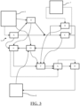
- FIG 4 is a schematic representation of the estimation and adjustment process 5 of the energy balance of the gas in liquid form during its repetition by iteration, that is to say when the estimation and adjustment process 5 is launched during the journey after having been launched a first time according to the Figure 3 .
- Most of the steps in the estimation and adjustment process 5 are similar to what has been described previously, and reference will therefore be made to the description of the Figure 3 for explanations concerning these.
- the solid arrows represent the progress of each of the steps of the estimation and adjustment method 5
- the dotted arrows correspond to a transmission of data between two steps of the estimation and adjustment method 5 or between an element of the system for managing the energy balance of gas in liquid form and a step of the estimation and adjustment method 5.
- Step A' of selecting the safety margin is also not repeated.
- the safety margin may, however, vary independently of the course of the estimation and adjustment method 5, either because it was set to vary over time when the estimation and adjustment method 5 was first launched, or because it was manually modified via the control monitor 6.
- the variation of the safety margin is the reason why step E is maintained within the estimation and adjustment method 5 since it is a factor that may vary over time for the calculation of step E.
- Step D also takes place in an identical manner to what was described previously.
- a step D' takes place, in parallel with step D, which also calculates the energy balance of the gas in liquid form at time t, but according to a calculation different from that of step D.
- the calculation of the energy balance of the gas in liquid form at time t of step D' is done from an energy balance of the gas in liquid form at a previous time t, calculated during a previous iteration of the estimation and adjustment method 5, as well as from the executions of the condensation and cooling functions since the departure of the floating structure.
- the energy balance of the gas in liquid form at a previous time t can be recovered for example from the buffer memory of the control box.
- the executions of the condensation and cooling functions are at the origin of heat transfer carried out by the condensation function and cold transfer carried out by the cooling function towards the cargo of gas in liquid form.
- the executions of the condensation and cooling functions can therefore be measured by sensors located at the level of the elements of the supply system 8 ensuring the condensation and cooling of the gas in liquid form, which transmits this data to the control box for application during step D'.
- the control box command is configured to repeat the estimation and adjustment process 5 at regular intervals throughout the journey, depending on the progress of the Figure 4 , for example once a day or every six hours.
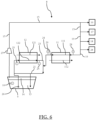
- FIG. 5 is a general representation of the supply system 8 ensuring the functions of condensation and cooling of the gas in liquid form.
- the supply system 8 interacts with the tank 9 as well as with a set of consumers.
- the feed system 8 is capable of managing the temperature of the gas in liquid form in the tank 9.
- the feed system 8 comprises a liquid inlet 81 and a gas inlet 82.
- the liquid inlet 81 connects the feed system 8 to the tank 9, and is capable of sucking in the gas in liquid form 13, for example by means of a gas pump in liquid form 26.
- the gas inlet 82 extends from a tank ceiling that may comprise a certain quantity of gaseous phase 14 generated from the gas in liquid form to the feed system 8.
- the gaseous phase 14 generated from the gas in liquid form can be sucked in for example by a compressor 27 in order to be conducted to the feed system 8.
- the supply system 8 can suck the gaseous phase 14 generated from the gas in liquid form into the gas inlet 82.
- the gaseous phase 14 generated from the gas in liquid form can then be treated by the supply system 8 and then exit the latter through the gas outlet 83, for example for the purpose of supplying the propulsion engine 16 or the electric generator 17.
- the gaseous phase 14 generated from the gas in liquid form and not used to power the propulsion engine 16 or the electric generator 17 represents the surplus gaseous phase 14 generated from the gas in liquid form.
- This surplus gaseous phase 14 generated from the gas in liquid form can be burned by the combustion chamber 18 or be released into the atmosphere by the degassing mat 28.
- the surplus gas phase 14 generated from the liquid gas can also return to the feed system 8 via a bypass 84 in order to be condensed by the latter. This being done, the condensed liquid gas returns to the tank 9 via a liquid outlet 85 of the feed system 8.
- liquid gas 13 If the liquid gas 13 needs to be cooled, it is drawn in by the liquid gas pump 26 and circulates through the liquid inlet 81 to the feed system 8 where it is cooled. The cooled liquid gas 13 then returns to the tank 9 via the liquid outlet 85.
- the condensation function of the supply system 8 makes it possible to condense the surplus gas phase 14 generated from the gas in liquid form.
- the gas phase 14 generated from the gas in liquid form in the tank 9 is sucked in by the compressor 27 located outside the tank and constituting a gas phase circuit 15.
- the gas phase circuit 15 transports the gas phase 14 generated from the gas in liquid form which extends until it opens at the propulsion engine 16 and/or the electric generator 17 for the purpose of being used as fuel by the latter.
- the condensed gas circulates in a condensed gas circuit 20 to a return circuit 21 which directs the condensed gas to the tank 9.
- the liquid gas 13 contained in the tank 9 is first sucked in by the liquid gas pump 26.
- the liquid gas 13 sucked in by the liquid gas pump 26 circulates to a second heat exchanger 12. It is the second heat exchanger 12 which ensures the cooling function of the liquid gas 13, thanks to a heat exchange between a third pass 121 and a fourth pass 122.
- the liquid gas 13 sucked in by the liquid gas pump 26 circulates in the second heat exchanger 12 via the fourth pass 122 and is cooled.
- a fluid with a temperature lower than the gas in liquid form 13 circulates within the third pass 121.
- the third pass 121 may be part of a refrigerant circuit external to the supply system 8, and not shown in the Figure 6
- the external refrigerant circuit can, for example, be part of a vacuum evaporator type system.
- the cooled gas in liquid form 13 returns to the tank 9 via the return circuit 21.
- the cooled gas in liquid form 13 makes it possible to generally cool the tank 9, the temperature of the cooled gas in liquid form 13 being lower than the temperature of the gas in liquid form 13 remaining in the tank 9.
- the heat exchanges of the first heat exchanger 11 and the second heat exchanger 12 are measured by a plurality of temperature sensors.
- the The feed system 8 comprises two second temperature sensors 24, each located at the inlet and outlet of the first heat exchanger 11, and two third temperature sensors 25, each located at the inlet and outlet of the second heat exchanger 12.
- the power supply system 8 receives the adjusted operating plans for the condensation and cooling functions.
- the power supply system 8 modifies its operation according to the adjusted operating plans by being able to program the activation or deactivation of one and/or the other of the condensation and cooling functions.
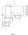
- FIG. 7 schematically represents a second embodiment of the power supply system 8. Compared to the first embodiment presented in Figure 6 , only the implementation of the cooling function of the power supply system 8 is different. We will therefore refer to the description of the Figure 6 for any part of the power supply system 8 common to both embodiments.
- the latter implements its cooling function in combination with a function of supplying the consumers of the floating structure. Indeed, when the gaseous phase 14 generated from the gas in liquid form is sucked into the gaseous phase circuit 15, it passes through the second exchanger 12, circulating within the third pass 121. The gas in liquid form 13 contained in the tank 9 is first sucked by the gas pump in liquid form 26 and then circulates through the fourth pass 122 located within the second heat exchanger 12.
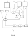
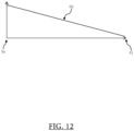
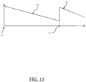
- the evolution of the energy balance of the gas in liquid form after time t is dotted and represents a forecast energy balance 35 which is therefore evaluated by the estimation and adjustment process, more precisely during step F and from the energy balance of the gas in liquid form at time t 38.
- the estimate of the energy balance 31 of the gas in liquid form contained in the tank at arrival 51 therefore corresponds to an estimate of the value of the energy balance when the floating structure reaches arrival 51 if the operating plans as presented on the figure 8 are maintained until this arrival 51.
- the invention achieves the aim it set itself, and makes it possible to propose a method for estimating and adjusting an energy balance of a gas in liquid form contained in a tank of a floating structure so that said energy balance of the gas in liquid form complies with the requirements of a destination location where the delivery of the gas in liquid form is intended, while at the same time adjusting the energy consumption of the supply system as best as possible.
- Variants not described here could be implemented without departing from the context of the invention, provided that, in accordance with the invention, they comprise a method for estimating and adjusting the energy balance in accordance with the invention.
Landscapes
- Engineering & Computer Science (AREA)
- Mechanical Engineering (AREA)
- General Engineering & Computer Science (AREA)
- Chemical & Material Sciences (AREA)
- Combustion & Propulsion (AREA)
- Ocean & Marine Engineering (AREA)
- Filling Or Discharging Of Gas Storage Vessels (AREA)
Claims (14)
- Verfahren zum Abschätzen und Einstellen (5) einer Energiebilanz eines Gases in flüssiger Form (13), das in mindestens einem Tank (9) einer schwimmenden Struktur (1) enthalten ist, die dazu bestimmt ist, das Gas in flüssiger Form (13) an einen bestimmten Bestimmungsort (2) zu liefern, wobei die schwimmende Struktur (1) ein System (8) zur Versorgung eines Verbrauchers der schwimmenden Struktur (1) mit Brennstoff umfasst, das in der Lage ist, eine Funktion der Kondensation einer Gasphase (14), die aus dem Gas in flüssiger Form erzeugt wird, und/oder eine Funktion der Kühlung des Gases in flüssiger Form (13) auszuführen, dadurch gekennzeichnet, dass das Schätz- und Einstellverfahren (5) die folgenden Schritte umfasst:- einen Schritt A zur Berechnung der maximal zulässigen Temperatur des im Tank enthaltenen Gases in flüssiger Form bei Ankunft am Bestimmungsort auf der Grundlage der Anforderungen an den maximalen Sättigungsdruck des Gases in flüssiger Form am Bestimmungsort (2) und der Eigenschaften des im Tank enthaltenen Gases in flüssiger Form,- einen Schritt B des Aufstellens eines ersten Betriebsplans (36) für die Funktion der Kondensation der Gasphase (14), die aus dem Gas in flüssiger Form erzeugt wird, die durch das Versorgungssystem (8) bis zur Ankunft (51) am Bestimmungsort (2) durchgeführt wird, wobei der erste Betriebsplan (36) ausgehend von einer Schätzung einer überschüssigen Gasphase (14), die aus dem Gas in flüssiger Form in dem Tank (9) während einer Fahrt (3) erzeugt wird, aufgestellt wird,- einen Schritt C des Aufstellens eines zweiten Betriebsplans (37) für die Kühlfunktion des Gases in flüssiger Form (13), die durch das Versorgungssystem (8) bis zur Ankunft (51) am Bestimmungsort (2) ausgeführt wird, wobei der zweite Betriebsplan (37) ausgehend von der Schätzung der überschüssigen Gasphase, die aus dem Gas in flüssiger Form während der Fahrt (3) erzeugt wird, aufgestellt wird,- einen Schritt D der Berechnung einer Energiebilanz des Gases in flüssiger Form zu einem Zeitpunkt t (38) aus der Temperatur des Gases in flüssiger Form (13), das in dem Tank (9) enthalten ist, und den Eigenschaften des Gases in flüssiger Form (13), das in dem Tank (9) enthalten ist,- einen Schritt E zur Berechnung einer maximalen Energiebilanz (32, 33) aus der in Schritt A berechneten maximal zulässigen Temperatur des Gases in flüssiger Form (13) und den Eigenschaften des im Tank (9) enthaltenen Gases in flüssiger Form (13),- einen Schritt F zur Schätzung der Energiebilanz (31) des im Tank enthaltenen Gases in flüssiger Form bei der Ankunft (51) von der Reise (3) aus den in den Schritten B und C bestimmten Betriebsplänen (36, 37) der Kondensations- und Kühlfunktionen und aus der in Schritt D bestimmten Energiebilanz des Gases in flüssiger Form zum Zeitpunkt t (38),- einen Schritt G der Anpassung des ersten Betriebsplans (36) und/oder des zweiten Betriebsplans (37),- einen Schritt H der Implementierung des Versorgungssystems (8) gemäß den Betriebsplänen (36, 37) der Kondensations- und Kühlfunktionen des Gases in flüssiger Form (13), die im Schritt G eingestellt wurden.
- Verfahren zum Schätzen und Einstellen (5) der Energiebilanz nach dem vorhergehenden Anspruch, wobei der Schritt G darin besteht, die Kondensationsfunktion zu aktivieren, solange die in Schritt F berechnete geschätzte Energiebilanz (31) des in dem Tank (51) enthaltenen Gases in flüssiger Form bei der Ankunft (3) von der Reise kleiner ist als die in Schritt E berechnete maximale Energiebilanz (32, 33).
- Verfahren zum Schätzen und Einstellen (5) der Energiebilanz nach einem der vorhergehenden Ansprüche, dadurch gekennzeichnet, dass der Schritt G darin besteht, die Kühlfunktion zu einem geschätzten Zeitpunkt dt zu stoppen, der gewährleistet, dass die in Schritt F berechnete geschätzte Energiebilanz (31) des im Tank enthaltenen Gases in flüssiger Form bei Ankunft (51) von der Reise (3) kleiner ist als die in Schritt E berechnete maximale Energiebilanz (32, 33).
- Verfahren zum Schätzen und Einstellen (5) der Energiebilanz nach Anspruch 1, dadurch gekennzeichnet, dass der Schritt G darin besteht, die Kondensationsfunktion zu stoppen, solange die in Schritt F berechnete geschätzte Energiebilanz (31) des im Tank enthaltenen Gases in flüssiger Form bei Ankunft (51) von der Reise (3) größer ist als die in Schritt E berechnete maximale Energiebilanz (32, 33).
- Verfahren zum Schätzen und Einstellen (5) der Energiebilanz nach Anspruch 1 oder 4, dadurch gekennzeichnet, dass Schritt G darin besteht, die Kühlfunktion zu aktivieren, solange die in Schritt F berechnete geschätzte Energiebilanz (31) des im Tank enthaltenen Gases in flüssiger Form bei Ankunft (51) von der Reise (3) größer ist als die in Schritt E berechnete maximale Energiebilanz (32, 33).
- Verfahren zum Schätzen und Einstellen (5) der Energiebilanz nach einem der vorhergehenden Ansprüche, wiederholt durch Iteration, beginnend mit Schritt B und während der Fahrt (3) der schwimmenden Struktur (1).
- Verfahren zum Schätzen und Einstellen (5) der Energiebilanz nach Anspruch 6, umfassend einen zusätzlichen Schritt D', der gleichzeitig mit Schritt D ausgeführt wird, zur Berechnung der Energiebilanz des Gases in flüssiger Form zum Zeitpunkt t (38) aus der Ausführung der Kondensations- und Kühlfunktionen ab dem Abgang (50) der schwimmenden Struktur (1) und bis zum Zeitpunkt t und aus einer Energiebilanz des Gases in flüssiger Form zum Zeitpunkt t (38), die während einer früheren Iteration berechnet wurde.
- Verfahren zum Schätzen und Einstellen (5) der Energiebilanz nach Anspruch 7, wobei die Energiebilanz des Gases in flüssiger Form zum Zeitpunkt t (38), die für Schritt F erhalten bleibt, die höchste ist unter der Energiebilanz des Gases in flüssiger Form zum Zeitpunkt t (38), die in Schritt D berechnet wurde, und der Energiebilanz des Gases in flüssiger Form zum Zeitpunkt t (38), die in Schritt D' berechnet wurde.
- Verfahren zum Schätzen und Einstellen (5) der Energiebilanz nach einem der Ansprüche 1 bis 5, mit einem zusätzlichen Schritt A' der Auswahl einer Sicherheitsspanne (60) für die maximale Energiebilanz (32, 33) des Gases in flüssiger Form (13) in Abhängigkeit von den Eigenschaften der Fahrt (3) der schwimmenden Struktur (1), wobei der Schritt E unter Berücksichtigung der Sicherheitsspanne (60) durchgeführt wird.
- Verfahren zum Schätzen und Einstellen (5) der Energiebilanz nach Anspruch 9, wobei Schritt A' während der Fahrt (3) der schwimmenden Struktur (1) iterativ wiederholt wird.
- Verfahren zum Schätzen und Einstellen (5) der Energiebilanz nach Anspruch 9 oder 10, wobei der Sicherheitsabstand (60) abnimmt, wenn sich die schwimmende Struktur (1) dem Bestimmungsort (2) nähert.
- Verfahren zum Schätzen und Einstellen (5) der Energiebilanz nach einem der vorhergehenden Ansprüche, wobei die schwimmende Struktur (1) mit mindestens einem Motor (16) ausgestattet ist, der zumindest teilweise durch die aus dem Gas in flüssiger Form erzeugte Gasphase (14) angetrieben wird, wobei die Schätzung der während der Fahrt (3) aus dem Gas in flüssiger Form erzeugten überschüssigen Gasphase aus einem Bildwert der Wärmeeinträge in den Tank (9) und einer Schätzung des Verbrauchs des Motors (16) ermittelt wird.
- System (4) zur Verwaltung einer Energiebilanz eines Gases in flüssiger Form (13), das in mindestens einem Tank (9) einer schwimmenden Struktur (1) enthalten ist, wobei das Verfahren (5) zum Schätzen und Einstellen nach einem der vorhergehenden Ansprüche durchgeführt wird, wobei das Verwaltungssystem (4) mindestens ein System (8) zur Versorgung eines Verbrauchers der schwimmenden Struktur (1) mit Kraftstoff und mindestens einen Rechner (7) umfasst, der die Aufgabe hat, eine Menge an überschüssiger Gasphase (14) zu schätzen, die aus dem Gas in flüssiger Form während einer Fahrt (3) der schwimmenden Struktur (1) erzeugt wird.
- Schwimmende Struktur (1) für den Transport von Gas in flüssiger Form (13), die ein System (4) zur Verwaltung der Energiebilanz des Gases gemäß dem vorhergehenden Anspruch umfasst.
Applications Claiming Priority (2)
| Application Number | Priority Date | Filing Date | Title |
|---|---|---|---|
| FR1915335A FR3105462B1 (fr) | 2019-12-20 | 2019-12-20 | Procédé d’estimation et d’ajustement d’un bilan énergie d’un gaz sous forme liquide contenu dans une cuve |
| PCT/FR2020/052560 WO2021123685A1 (fr) | 2019-12-20 | 2020-12-18 | Procédé d'estimation et d'ajustement d'un bilan énergie d'un gaz sous forme liquide contenu dans une cuve |
Publications (3)
| Publication Number | Publication Date |
|---|---|
| EP4078014A1 EP4078014A1 (de) | 2022-10-26 |
| EP4078014B1 true EP4078014B1 (de) | 2025-07-02 |
| EP4078014C0 EP4078014C0 (de) | 2025-07-02 |
Family
ID=70008792
Family Applications (1)
| Application Number | Title | Priority Date | Filing Date |
|---|---|---|---|
| EP20848857.7A Active EP4078014B1 (de) | 2019-12-20 | 2020-12-18 | Verfahren zur schätzung und einstellung einer energiebilanz eines in einem tank enthaltenen gases in flüssiger form |
Country Status (6)
| Country | Link |
|---|---|
| EP (1) | EP4078014B1 (de) |
| JP (1) | JP7551756B2 (de) |
| KR (1) | KR102856693B1 (de) |
| CN (1) | CN115135921B (de) |
| FR (1) | FR3105462B1 (de) |
| WO (1) | WO2021123685A1 (de) |
Families Citing this family (1)
| Publication number | Priority date | Publication date | Assignee | Title |
|---|---|---|---|---|
| JP2025021741A (ja) * | 2023-08-01 | 2025-02-14 | 三菱造船株式会社 | 二酸化炭素計量システム、船舶、及び二酸化炭素計量方法 |
Family Cites Families (14)
| Publication number | Priority date | Publication date | Assignee | Title |
|---|---|---|---|---|
| US7448223B2 (en) * | 2004-10-01 | 2008-11-11 | Dq Holdings, Llc | Method of unloading and vaporizing natural gas |
| FR2877078B1 (fr) * | 2004-10-25 | 2007-02-02 | Snecma Moteurs Sa | Systeme energetique mettant en oeuvre du gaz naturel stocke sous forme liquide et des machines thermoelectriques |
| US8820096B2 (en) * | 2007-02-12 | 2014-09-02 | Daewoo Shipbuilding & Marine Engineering Co., Ltd. | LNG tank and operation of the same |
| EP2003389A3 (de) * | 2007-06-15 | 2017-04-19 | Daewoo Shipbuilding & Marine Engineering Co., Ltd | Verfahren und Vorrichtung zum Behandeln von Boil-off-Gas bei einem LNG-Tanker mit Rückverflüssigungsanlage und LNG-Tanker mit dieser Vorrichtung zur Behandlung von Boil-off-Gas |
| FR2938498B1 (fr) * | 2008-11-17 | 2012-02-03 | Gaztransp Et Technigaz | Navire ou support flottant equipe d'un dispositif d'attenuation des mouvements de carenes liquides |
| FR2987100B1 (fr) | 2012-02-20 | 2015-04-10 | Gaztransp Et Technigaz | Elements calorifuge pour cuve etanche et thermiquement isolee |
| CN106460571A (zh) * | 2014-04-19 | 2017-02-22 | 多田雅史 | 冷能利用系统、具备冷能利用系统的能量系统以及冷能利用系统的利用方法 |
| FR3028305A1 (fr) | 2014-11-10 | 2016-05-13 | Gaztransport Et Technigaz | Dispositif et procede de refroidissement d'un gaz liquefie |
| FR3045775B1 (fr) * | 2015-12-18 | 2018-07-06 | Engie | Procede et systeme pour calculer en temps reel la duree d'autonomie d'une cuve non refrigeree contenant du gnl |
| JP6882859B2 (ja) * | 2016-07-05 | 2021-06-02 | 川崎重工業株式会社 | 運航管理システム |
| WO2018189789A1 (ja) * | 2017-04-10 | 2018-10-18 | 日本郵船株式会社 | タンク状態推定方法およびタンク状態推定プログラム |
| JP7108017B2 (ja) * | 2017-07-31 | 2022-07-27 | デウ シップビルディング アンド マリン エンジニアリング カンパニー リミテッド | 船舶用蒸発ガス再液化システムおよび方法、ならびに船舶用蒸発ガス再液化システムの起動方法 |
| JP6959801B2 (ja) * | 2017-08-31 | 2021-11-05 | 川崎重工業株式会社 | スプレー気化率予測方法及び装置、並びに、液化ガス運搬船の運航支援方法及びシステム |
| FR3077867B1 (fr) * | 2018-02-09 | 2020-01-31 | Gaztransport Et Technigaz | Procede et systeme de traitement de gaz d'une installation de stockage de gaz pour un navire de transport de gaz |
-
2019
- 2019-12-20 FR FR1915335A patent/FR3105462B1/fr active Active
-
2020
- 2020-12-18 JP JP2022537734A patent/JP7551756B2/ja active Active
- 2020-12-18 CN CN202080097172.9A patent/CN115135921B/zh active Active
- 2020-12-18 KR KR1020227024712A patent/KR102856693B1/ko active Active
- 2020-12-18 EP EP20848857.7A patent/EP4078014B1/de active Active
- 2020-12-18 WO PCT/FR2020/052560 patent/WO2021123685A1/fr not_active Ceased
Also Published As
| Publication number | Publication date |
|---|---|
| WO2021123685A1 (fr) | 2021-06-24 |
| JP2023507467A (ja) | 2023-02-22 |
| FR3105462A1 (fr) | 2021-06-25 |
| FR3105462B1 (fr) | 2021-12-03 |
| JP7551756B2 (ja) | 2024-09-17 |
| EP4078014A1 (de) | 2022-10-26 |
| CN115135921B (zh) | 2025-03-25 |
| KR102856693B1 (ko) | 2025-09-08 |
| CN115135921A (zh) | 2022-09-30 |
| EP4078014C0 (de) | 2025-07-02 |
| KR20220119654A (ko) | 2022-08-30 |
Similar Documents
| Publication | Publication Date | Title |
|---|---|---|
| EP3628911B1 (de) | Füllvorrichtung und -verfahren für druckgastanks | |
| EP4158170B1 (de) | Vorrichtung zur druckregelung eines kryogenen flugzeugkraftstofftanks | |
| EP1596122B1 (de) | Anlage zur Abgabe von brennbaren Gas zur Antrieb eines Bootes für den Transport von flüssigen Gasen | |
| JP6449650B2 (ja) | 液化ガス処理システム及びその方法 | |
| EP3510317B1 (de) | Anlage, verfahren zur lagerung und verflüssigung eines verflüssigten gases und zugehöriges transportfahrzeug | |
| EP4078014B1 (de) | Verfahren zur schätzung und einstellung einer energiebilanz eines in einem tank enthaltenen gases in flüssiger form | |
| EP3172499B1 (de) | Kälteerzeugungsvorrichtung mit mittel zur gleichzeitigen kondensation durch luft und verfahren zur implementierung dieser einrichtung | |
| FR3093785A1 (fr) | Système de contrôle de pression dans une cuve de gaz naturel liquéfié. | |
| WO2007063119A1 (fr) | Unite solaire de production frigorifique pour installation de climatisation, unite solaire de production calorifique, dispositifs et procede de controle correspondants | |
| EP2795714B1 (de) | Wärmespeichernde vorrichtung zum erwärmen einer fahrzeugbatterie | |
| EP4256225B1 (de) | Verfahren und system zur unterstützung der verwaltung eines flüssiggastransportschiffs vom typ, das verdampftes gas für seinen antrieb verbraucht | |
| EP1511965B1 (de) | Verfahren und anlage zum steuern mindestens eines kryogenen zentrifugalkompressors, druckleitung | |
| EP2556229B1 (de) | Verfahren zur kalkulation der ausgangstemperatur eines mechanischen elements eines fahrzeuges beim fahrzeugstart | |
| RU2831875C1 (ru) | Способ оценки и регулирования энергетического баланса газа в жидком состоянии, содержащегося в резервуаре | |
| FR3002974A1 (fr) | Dispositif de demarrage de moteur thermique de vehicule automobile a mise en pression d'huile de lubrification | |
| FR3071276A1 (fr) | Dispositif et procede d'alimentation en gaz a indice de methane optimise d'au moins un moteur thermique, en particulier d'un navire de transport de gaz liquefie | |
| EP3601056B1 (de) | Verfahren zur steuerung eines mehrfachmotorraums, steuerungssystem für einen mehrfachmotorraum und mehrfachmotorraum | |
| EP4019745B1 (de) | Verfahren zum speichern von energie in einem dampfakkumulator | |
| WO2025257499A1 (fr) | Procede d'alimentation en gaz d'un appareil consommateur de gaz d'un ouvrage flottant | |
| WO2025125737A1 (fr) | Système d'alimentation en gaz d'un ouvrage flottant | |
| FR3155282A1 (fr) | Procédé pour réduire des pertes par évaporation d’hydrogène | |
| EP4253822A1 (de) | Gasversorgungssystem für gasverbrauchergeräte mit hohem und niedrigem druck und verfahren zur steuerung eines solchen systems | |
| WO2017182724A1 (fr) | Procede d'optimisation d'un temps de redemarrage d'un moteur thermique par pilotage de la pression dans un rail d'injection | |
| FR3051512A1 (fr) | Systeme de production d'energie thermique a au moins un accumulateur de vapeur de stockage d'energie thermique provenant d'une installation solaire |
Legal Events
| Date | Code | Title | Description |
|---|---|---|---|
| STAA | Information on the status of an ep patent application or granted ep patent |
Free format text: STATUS: UNKNOWN |
|
| STAA | Information on the status of an ep patent application or granted ep patent |
Free format text: STATUS: THE INTERNATIONAL PUBLICATION HAS BEEN MADE |
|
| PUAI | Public reference made under article 153(3) epc to a published international application that has entered the european phase |
Free format text: ORIGINAL CODE: 0009012 |
|
| STAA | Information on the status of an ep patent application or granted ep patent |
Free format text: STATUS: REQUEST FOR EXAMINATION WAS MADE |
|
| 17P | Request for examination filed |
Effective date: 20220627 |
|
| AK | Designated contracting states |
Kind code of ref document: A1 Designated state(s): AL AT BE BG CH CY CZ DE DK EE ES FI FR GB GR HR HU IE IS IT LI LT LU LV MC MK MT NL NO PL PT RO RS SE SI SK SM TR |
|
| DAV | Request for validation of the european patent (deleted) | ||
| DAX | Request for extension of the european patent (deleted) | ||
| GRAP | Despatch of communication of intention to grant a patent |
Free format text: ORIGINAL CODE: EPIDOSNIGR1 |
|
| STAA | Information on the status of an ep patent application or granted ep patent |
Free format text: STATUS: GRANT OF PATENT IS INTENDED |
|
| INTG | Intention to grant announced |
Effective date: 20250212 |
|
| GRAS | Grant fee paid |
Free format text: ORIGINAL CODE: EPIDOSNIGR3 |
|
| GRAA | (expected) grant |
Free format text: ORIGINAL CODE: 0009210 |
|
| STAA | Information on the status of an ep patent application or granted ep patent |
Free format text: STATUS: THE PATENT HAS BEEN GRANTED |
|
| AK | Designated contracting states |
Kind code of ref document: B1 Designated state(s): AL AT BE BG CH CY CZ DE DK EE ES FI FR GB GR HR HU IE IS IT LI LT LU LV MC MK MT NL NO PL PT RO RS SE SI SK SM TR |
|
| REG | Reference to a national code |
Ref country code: GB Ref legal event code: FG4D Free format text: NOT ENGLISH |
|
| REG | Reference to a national code |
Ref country code: CH Ref legal event code: EP |
|
| REG | Reference to a national code |
Ref country code: DE Ref legal event code: R096 Ref document number: 602020053961 Country of ref document: DE |
|
| REG | Reference to a national code |
Ref country code: IE Ref legal event code: FG4D Free format text: LANGUAGE OF EP DOCUMENT: FRENCH |
|
| U01 | Request for unitary effect filed |
Effective date: 20250715 |
|
| U07 | Unitary effect registered |
Designated state(s): AT BE BG DE DK EE FI FR IT LT LU LV MT NL PT RO SE SI Effective date: 20250721 |
|
| PGFP | Annual fee paid to national office [announced via postgrant information from national office to epo] |
Ref country code: NO Payment date: 20250926 Year of fee payment: 6 |
|
| U20 | Renewal fee for the european patent with unitary effect paid |
Year of fee payment: 6 Effective date: 20251022 |
|
| PG25 | Lapsed in a contracting state [announced via postgrant information from national office to epo] |
Ref country code: IS Free format text: LAPSE BECAUSE OF FAILURE TO SUBMIT A TRANSLATION OF THE DESCRIPTION OR TO PAY THE FEE WITHIN THE PRESCRIBED TIME-LIMIT Effective date: 20251102 |
|
| PG25 | Lapsed in a contracting state [announced via postgrant information from national office to epo] |
Ref country code: HR Free format text: LAPSE BECAUSE OF FAILURE TO SUBMIT A TRANSLATION OF THE DESCRIPTION OR TO PAY THE FEE WITHIN THE PRESCRIBED TIME-LIMIT Effective date: 20250702 |
|
| PG25 | Lapsed in a contracting state [announced via postgrant information from national office to epo] |
Ref country code: GR Free format text: LAPSE BECAUSE OF FAILURE TO SUBMIT A TRANSLATION OF THE DESCRIPTION OR TO PAY THE FEE WITHIN THE PRESCRIBED TIME-LIMIT Effective date: 20251003 |
|
| PG25 | Lapsed in a contracting state [announced via postgrant information from national office to epo] |
Ref country code: CZ Free format text: LAPSE BECAUSE OF FAILURE TO SUBMIT A TRANSLATION OF THE DESCRIPTION OR TO PAY THE FEE WITHIN THE PRESCRIBED TIME-LIMIT Effective date: 20250702 |
|
| PG25 | Lapsed in a contracting state [announced via postgrant information from national office to epo] |
Ref country code: PL Free format text: LAPSE BECAUSE OF FAILURE TO SUBMIT A TRANSLATION OF THE DESCRIPTION OR TO PAY THE FEE WITHIN THE PRESCRIBED TIME-LIMIT Effective date: 20250702 |
|
| PG25 | Lapsed in a contracting state [announced via postgrant information from national office to epo] |
Ref country code: RS Free format text: LAPSE BECAUSE OF FAILURE TO SUBMIT A TRANSLATION OF THE DESCRIPTION OR TO PAY THE FEE WITHIN THE PRESCRIBED TIME-LIMIT Effective date: 20251002 |
|
| PG25 | Lapsed in a contracting state [announced via postgrant information from national office to epo] |
Ref country code: ES Free format text: LAPSE BECAUSE OF FAILURE TO SUBMIT A TRANSLATION OF THE DESCRIPTION OR TO PAY THE FEE WITHIN THE PRESCRIBED TIME-LIMIT Effective date: 20250702 |