EP4019745B1 - Verfahren zum speichern von energie in einem dampfakkumulator - Google Patents
Verfahren zum speichern von energie in einem dampfakkumulator Download PDFInfo
- Publication number
- EP4019745B1 EP4019745B1 EP21216729.0A EP21216729A EP4019745B1 EP 4019745 B1 EP4019745 B1 EP 4019745B1 EP 21216729 A EP21216729 A EP 21216729A EP 4019745 B1 EP4019745 B1 EP 4019745B1
- Authority
- EP
- European Patent Office
- Prior art keywords
- gas
- flow rate
- gas flow
- tank
- liquid
- Prior art date
- Legal status (The legal status is an assumption and is not a legal conclusion. Google has not performed a legal analysis and makes no representation as to the accuracy of the status listed.)
- Active
Links
Images


Classifications
-
- F—MECHANICAL ENGINEERING; LIGHTING; HEATING; WEAPONS; BLASTING
- F01—MACHINES OR ENGINES IN GENERAL; ENGINE PLANTS IN GENERAL; STEAM ENGINES
- F01K—STEAM ENGINE PLANTS; STEAM ACCUMULATORS; ENGINE PLANTS NOT OTHERWISE PROVIDED FOR; ENGINES USING SPECIAL WORKING FLUIDS OR CYCLES
- F01K1/00—Steam accumulators
- F01K1/08—Charging or discharging of accumulators with steam
-
- F—MECHANICAL ENGINEERING; LIGHTING; HEATING; WEAPONS; BLASTING
- F28—HEAT EXCHANGE IN GENERAL
- F28D—HEAT-EXCHANGE APPARATUS, NOT PROVIDED FOR IN ANOTHER SUBCLASS, IN WHICH THE HEAT-EXCHANGE MEDIA DO NOT COME INTO DIRECT CONTACT
- F28D20/00—Heat storage plants or apparatus in general; Regenerative heat-exchange apparatus not covered by groups F28D17/00 or F28D19/00
- F28D20/02—Heat storage plants or apparatus in general; Regenerative heat-exchange apparatus not covered by groups F28D17/00 or F28D19/00 using latent heat
- F28D20/025—Heat storage plants or apparatus in general; Regenerative heat-exchange apparatus not covered by groups F28D17/00 or F28D19/00 using latent heat the latent heat storage material being in direct contact with a heat-exchange medium or with another heat storage material
-
- Y—GENERAL TAGGING OF NEW TECHNOLOGICAL DEVELOPMENTS; GENERAL TAGGING OF CROSS-SECTIONAL TECHNOLOGIES SPANNING OVER SEVERAL SECTIONS OF THE IPC; TECHNICAL SUBJECTS COVERED BY FORMER USPC CROSS-REFERENCE ART COLLECTIONS [XRACs] AND DIGESTS
- Y02—TECHNOLOGIES OR APPLICATIONS FOR MITIGATION OR ADAPTATION AGAINST CLIMATE CHANGE
- Y02E—REDUCTION OF GREENHOUSE GAS [GHG] EMISSIONS, RELATED TO ENERGY GENERATION, TRANSMISSION OR DISTRIBUTION
- Y02E60/00—Enabling technologies; Technologies with a potential or indirect contribution to GHG emissions mitigation
- Y02E60/14—Thermal energy storage
Definitions
- the present invention relates to the field of steam accumulators. It finds a particularly advantageous application in the storage of energy in a steam accumulator by direct condensation, in particular when the stored gas comprises non-condensable gases such as, for example, in the case of geothermal energy or thermodynamic power plants for producing electricity.
- Water vapor is one of the heat transfer fluids frequently used in industry. It has the advantage of being able to transport a large quantity of heat per unit of mass: because it transports it largely in the form of latent heat, by its liquid-vapor phase transition.
- This heat transfer fluid can, for example, be used to produce electricity in thermodynamic power plants.
- steam storage makes it possible to store thermal energy during periods when electricity demand is low in order to release it during peaks in electricity consumption in order to limit the use of fossil fuel backup means.
- steam accumulators There are several ways to store steam including direct condensation, for example by storing it in pressurized liquid water tanks called steam accumulators.
- the steam may contain non-condensable gases such as carbon dioxide (CO2).
- CO2 carbon dioxide
- the aim of the present invention is to propose a solution which makes it possible to limit the impact of non-condensable gases on the storage capacity of a steam accumulator.
- the invention provides a method for storing thermal energy in a steam accumulator comprising a tank according to claim 1, advantageously closed, preferably pressure-tight, containing a liquid and a gas ceiling arranged above the liquid, a device for injecting gas entering the tank and a device for discharging gas leaving the tank, the gas comprising steam and at least one non-condensable gas.
- the method according to the invention thus makes it possible to limit the partial pressure of non-condensable gas in the tank and more specifically in the gas headspace located above the liquid contained in the tank.
- the partial pressure of gas in the tank is conventionally the parameter limiting the energy capacity of the accumulator, because the partial pressure of gas limits the partial pressure of vapor for a fixed total gas pressure.
- the storage capacity of a steam accumulator is therefore optimized by the present method.
- the present invention makes it possible to apply the storage method to thermal storage systems of the existing steam accumulator type.
- the invention makes it possible to increase the storage capacity without increasing the size of the accumulator or the maximum operating pressure of the storage.
- the storage capacity increases.
- the same amount of energy can therefore be stored in a smaller volume accumulator, which reduces the cost of the installation or, for the same volume of accumulator, a larger quantity energy will be stored, allowing for a more cost-effective installation.
- a steam accumulator comprising a tank according to claim 14, advantageously closed, preferably pressure-tight, containing a liquid and a gas ceiling, a device for injecting gas entering the tank, a device for discharging gas leaving the tank, a management module comprising a computer and a control unit comprising control valves for the gas injection device and the device for discharging gas leaving the tank.
- the gas discharge at a second gas flow rate is intermittent during the charging phase.
- the gas discharge at a second gas flow rate is continuous during the charging phase. This arrangement ensures great ease of management of the charging phase.
- the second gas flow rate is lower than the first gas flow rate. In this way, charging is achieved while limiting the partial pressure of non-condensable gas in the tank.
- gas evacuation at a second gas flow rate is carried out from the gas ceiling.
- the injection of gas at a first gas flow rate is continuous during the charging phase.
- the gas injection at a first gas flow rate comprises a main gas flow rate and a complementary gas flow rate.
- the first gas flow rate consists of a main gas flow rate and a complementary gas flow rate.
- the injection of gas at a complementary gas flow rate is intermittent during the charging phase.
- the first gas flow is continuous during the charging phase, but the first gas flow is variable, it increases and decreases depending on the intermittency of the complementary flow.
- the injection of gas at a complementary gas flow rate is continuous during the charging phase.
- the injection of gas at a complementary gas flow rate is carried out into the liquid contained in the tank. This arrangement makes it possible to optimize the thermodynamic balance between the liquid and the gas ceiling.
- the injection of gas at a complementary gas flow rate is carried out in a gas ceiling arranged above the liquid contained in the tank.
- the gas ceiling is swept by the complementary flow rate. Control of the charging phase is facilitated according to this embodiment.
- the additional gas flow rate is less than the main gas flow rate.
- the additional gas flow rate corresponds to at least partially compensating for the second gas discharge flow rate so as to, in particular, comply with an identical charging time setpoint, regardless of the fraction of non-condensable gas accompanying the vapor in the gas.
- the second gas flow rate is greater than or equal to the supplemental gas flow rate.
- the liquid contained in the tank is water and the gas vapor is water vapor comprising at least one non-condensable gas.
- flow rate is understood as a mass flow rate in kg/s.
- the amount of non-condensable gas in the gas comprising the vapor is given as a mass fraction or percentage relative to the total mass quantity of gas.
- a steam accumulator comprises a tank 1 containing a liquid 2 and a gas layer 3.
- the tank is advantageously closed, more preferably sealed so as to maintain the fluids: the liquid 2 and the gas layer 3, inside the tank 1.
- the tank 1 is advantageously configured to allow the liquid 2 and the gas layer 3 to be pressurized.
- the tank 1 is advantageously sealed against gases and liquids.
- the tank 1 comprises a gas injection device 5 and a gas evacuation device.
- the gas injection device 5 is intended to inject a gas into the tank 1.
- the gas is steam, for example water vapor comprising at least at least one incondensable gas.
- the gas injection is at least partially carried out in the liquid 2.
- the injection device comprises an injector 10 for example in the form of an injection line plunging into the liquid 2 of the tank 1, preferably in the lower part.
- the injection line comprises for example a plurality of outlets preferably distributed in the tank 1.
- the gas injection by the gas injection device 5 is carried out at a first gas flow rate.
- the gas evacuation device is intended to evacuate the gas from the tank 1.
- the gas evacuation is carried out from the gas head 3.
- the gas is steam, for example water vapor comprising at least one undesirable gas.
- the evacuation device comprises an evacuation pipe 4 opening at one end into the tank 1 and extending outside the tank 1. The gas evacuation by the gas evacuation device is carried out at a second gas flow rate.
- the tank 1 comprises a device 6 for filling and emptying the liquid 2.
- the device 6 for filling and emptying the liquid 2 is used to fill or empty the tank 1 with liquid 2.
- this device 6 for filling and emptying is arranged in the lower part of the tank 1 to facilitate its emptying.
- the device 6 for filling and emptying comprises a valve 9 ensuring the opening and closing of the device 6 for filling and emptying the tank 1 to control the filling and emptying.
- the steam accumulator comprises, according to one embodiment, a control unit comprising controlled valves for controlling the injection and evacuation of gas into and out of the tank 1.
- the control unit advantageously comprises an evacuation valve 7 arranged on the evacuation device, preferably on the evacuation pipe 4.
- the evacuation valve 7 makes it possible to initiate or stop the evacuation of gas from the tank 1.
- the evacuation valve 7 is configured to control the second flow rate, i.e. the gas evacuation flow rate.
- the control unit advantageously comprises an injection valve 8 arranged on the injection device 5, preferably on the injection line.
- the injection valve 8 makes it possible to initiate or stop the injection of gas into the tank 1.
- the injection valve 8 is configured to control the first flow rate, i.e. the gas injection flow rate.
- the accumulator comprises, according to one possibility, at least one measuring device, in particular for operating parameters of the accumulator.
- At least one device measuring device is a pressure sensor of the total pressure in tank 1.
- the steam accumulator comprises, according to one embodiment, a management module.
- the management module is intended to optimize the storage capacity of the accumulator as a function of the mass fraction of non-condensable gas in the vapor of the stored gas.
- the management module preferably comprises traditional computing means, in particular a processor, a memory, and a computer program stored in the memory and comprising a series of instructions configured to process input data, in particular received from measuring devices or data from the accumulator.
- the invention advantageously relates to thermal storage in the form of steam by direct condensation.
- the steam is accumulated in the tank 1 containing a liquid 2 under pressure.
- the liquid 2 contained in the tank 1 is water in the liquid state while the gas comprises vapor such as water vapor and at least one non-condensable gas.
- a steam accumulator operates to implement a method of storing thermal energy.
- the method of storing thermal energy comprises a charging phase during which thermal energy is stored in the accumulator.
- the method advantageously comprises a discharging phase during which thermal energy is released from the accumulator.
- gas is understood to mean a mixture of gases comprising vapor such as water vapor and at least one non-condensable gas.
- Non-condensable gas is a gas that cannot be condensed under the conditions of use of the steam accumulator.
- Non-condensable gases are, for example, carbon dioxide CO2 or H2S, N2, CH4, Ar, O2, H2, He, C2H6, C3H8.
- the steam may contain non-condensable gases.
- the charging phase allows thermal energy to be stored in the form of steam.
- tank 1 contains a quantity of liquid 2 at saturation and a gas ceiling 3 saturated at the minimum operating pressure.
- the valve discharge 7 is closed.
- a gas at a higher pressure than the pressure in the tank 1 is injected, preferably through the bottom of the tank 1, through the injection device 5.
- the loading valve 8 is open.
- the vapor bubbles condense on contact with the colder liquid 2 and release energy, which increases the temperature of the liquid 2. If the liquid 2 and the gas headspace 3 are in thermodynamic equilibrium, this increase in temperature results in an increase in the pressure in the tank 1 by evaporation of the liquid 2 at its free surface. If the thickness of the liquid 2 is insufficient to ensure the condensation of all the vapor in contact with the liquid 2, the increase in pressure in the tank 1 is linked to the accumulation of vapor in the gas headspace 3. This vapor, at overpressure relative to the saturation pressure, condenses on the free surface of the liquid 2 to tend towards thermodynamic equilibrium.
- the free surface of the liquid is understood as the surface of the liquid 2 at the interface with the gas sky 3.
- Liquid level 2 also increases, resulting from the condensation of the injected steam.
- the pressure in the tank 1 increases, possibly continuously.
- the storage stops when the pressure reaches a target maximum pressure.
- the target pressure is the pressure of the injection device 5, more precisely the maximum pressure of the injected gas.
- the liquid level and the pressure are maximum at the end of the charging phase.
- the discharge phase is described below.
- the discharge phase is intended to provide thermal energy in the form of steam to a final source.
- the final source may be a steam turbine.
- the injection device 5 is closed, preferably the charging valve 8 is closed.
- the discharge valve 7 is open.
- the pressure in the tank 1 decreases, causing the liquid 2 to vaporize.
- the liquid 2 is at a temperature very slightly higher than the saturation temperature, causing the liquid 2 to vaporize rapidly.
- This vaporization requires energy, latent heat of vaporization, which is provided by the liquid 2.
- the temperature of the liquid 2 decreases accordingly.
- the level of the liquid 2 decreases during this discharge phase, because part of the liquid 2 is evaporated.
- the accumulator produces saturated steam.
- This discharge phase stops when tank 1 reaches a minimum pressure target.
- the target minimum pressure is a function of the minimum pressure accepted by the final source.
- thermodynamic equilibrium It may happen that there is a thermodynamic imbalance with a pressure higher than the equilibrium pressure at the charge and a lower pressure at the discharge. The hypothesis of thermodynamic equilibrium is therefore favorable. The imbalance is unfavorable by interrupting the charge and discharge earlier.
- the gas injected into the accumulator comprises at least one non-condensable gas.
- the presence of the latter in the steam has a significant impact on the storage capacity of a steam accumulator.
- the tank is closed, its storage capacity decreases sharply, because the non-condensable gases transported by the injected steam accumulate in the gas 3 headspace during the charging phase.
- the partial pressure of non-condensable gases increases during the charging phase to the detriment of the partial pressure of steam.
- the latter is then lower than the maximum target pressure also called total end-of-charging pressure which is a predefined value.
- the temperature of the liquid follows the pressure of the steam.
- the final temperature of liquid 2 in tank 1 will therefore be lower than it would have been in the absence of non-condensable gas. Since the stored energy is proportional in the first order to the temperature rise, less energy will be stored in tank 1 in the presence of non-condensable gases. This reduction in energy due to a lower partial pressure of the steam is illustrated in Figures 2 and 3 corresponding to example 1.
- the decrease in stored energy is all the more marked as the fraction of non-condensable gas is high, as illustrated in figure 8 .
- the present invention proposes that during the charging phase, the presence of non-condensable gas is compensated by management of the pressure of the gas ceiling 3 to reduce the partial pressure of non-condensable gas in favor of the partial pressure of vapor.
- the charging phase includes, in addition to the injection of a gas at a first flow rate into the tank 1 of the accumulator, an evacuation of gas at a second flow rate from gas sky 3.
- the charging phase therefore comprises an injection of gas at a first gas flow rate.
- the injected gas comprises a fraction of non-condensable gas.
- the injected gas is a mixture of steam, preferably water vapor, and at least one non-condensable gas.
- the gas is injected by a gas injection device 5.
- the gas is preferably injected continuously throughout the charging phase at a first gas flow rate which may be stable or variable.
- the method also comprises an evacuation, which may also be called gas extraction advantageously from the gas ceiling 3.
- an evacuation which may also be called gas extraction advantageously from the gas ceiling 3.
- the evacuation of gas during the charging phase is carried out by the gas evacuation pipe 4 also used for the evacuation of gas during the discharge phase, as illustrated in FIG. Figures 1A and 1B .
- the gas evacuation during the charging phase is done by an evacuation 14, preferably equipped with a discharge valve 13.
- the gas evacuation during the discharge phase is carried out by the different evacuation pipe 4 as illustrated in FIG. Figure 1C .
- the evacuation device comprises a gas evacuation 14 separate from the evacuation pipe 4 used for the discharge phase. This second possibility makes it possible in particular to adapt the evacuation to the evacuated flow rate.
- the evacuated flow rate is lower than that evacuated in the discharge phase so that the diameters of the evacuation pipe 4 and the evacuation 14 are thus adapted.
- the evacuated gas corresponds to the gas in the gas ceiling 3.
- the evacuated gas comprises a fraction of non-condensable gas.
- the evacuated gas is a mixture of vapor, preferably water vapor, and at least one non-condensable gas.
- the gas is discharged continuously or intermittently at a second gas flow rate which can be stable or variable during the charging phase.
- the second gas flow rate is advantageously lower than the first gas flow rate so as to allow the accumulator to be charged, i.e. the pressure in the tank 1 and therefore the stored energy to be increased.
- the second gas flow rate represents from 2% to 50% of the first gas flow rate.
- the gas is evacuated from the gas ceiling 3.
- the second gas flow is advantageously controlled by the control unit and in particular an evacuation valve 7.
- the gas is evacuated during the entire charging phase at a stable or variable flow rate, the gas evacuation is continuous.
- the gas is evacuated intermittently during the charging phase, i.e. that at least one degassing, preferably successive degassings, take place.
- the second gas flow is then either identical during all degassings or different.
- the injection of gas at a first flow rate comprises a main flow rate and a complementary gas flow rate.
- the first gas flow is the sum of the main gas flow and the complementary gas flow.
- the injection of gas at the main flow rate is advantageously continuous during the charging phase and carried out in liquid 2.
- the gas injection at the additional flow rate may be continuous during the charging phase or may be intermittent.
- the gas injection at the additional flow rate is intended to at least partially compensate for the gas evacuation.
- the additional flow rate increases the injected gas flow rate compared to a prior art accumulator providing a charging phase without gas evacuation.
- the additional flow rate may be stable or variable during charging.
- the injection of gas at the complementary flow rate is carried out by the injection device 5.
- the injection of gas at the complementary flow rate is carried out in the liquid 2.
- the injection of gas at the complementary gas flow rate is preferably carried out by the same injection device 5 as the injection of gas at the main flow rate, that is to say for example the injection line illustrated in Figure 1A . It may be necessary to oversize the injection device 5.
- the valve 8 ensures the control of the injection and advantageously also of the first flow rate of injected gas.
- the injection device 5 comprises an injector 10 for the injection of gas at the main flow rate and a complementary injector 11 for the injection of gas at the complementary flow rate.
- the complementary injector 11 is arranged in the tank 1 immersed in the liquid 2 preferably in the lower part.
- the complementary injection 11 comprises a complementary valve 12 controlling the injection of complementary gas and advantageously the flow rate of complementary gas.
- the injection of gas at the complementary flow rate is carried out in the gas head 3.
- the injection of gas at the complementary gas flow rate is preferentially carried out by the injection device 5 comprising an injector 10 for the injection of gas at the main flow rate and a additional injector 11 for injecting gas at the additional flow rate.
- the additional injector 11 is arranged in the tank in the gas ceiling 3.
- the additional injection 11 comprises a complementary valve 12 controlling the injection of additional gas and advantageously the flow rate of additional gas.
- the gas injection is continuous at a first main flow rate which can be stable or variable during the charging phase.
- the gas injection is continuous at the first complementary flow rate which can be stable or variable during the charging phase.
- the gas evacuation is continuous at the second flow rate which can be stable or variable.
- the gas injection is continuous at the first main gas flow rate which can be stable or variable during the charging phase.
- the gas injection is intermittent at the first complementary flow rate which can be stable or variable during the charging phase.
- the gas evacuation is continuous at the second flow rate which can be stable or variable during the charging phase.
- the gas injection at the complementary flow rate and the gas evacuation at the second flow rate can be carried out alternately or simultaneously, without being dependent on each other.
- the method according to the invention is intended to control the first gas flow rate and the second gas flow rate as a function of the mass fraction of non-condensable gas in order to achieve optimal energy storage.
- the management module controls the first gas flow rate and the second gas flow rate as a function of the non-condensable gas fraction, preferably also the maximum target pressure and the minimum target pressure of the accumulator, preferably also the pressure measured by the pressure measuring device, preferably also the desired charging duration.
- the gas extracted by the evacuation device during the charging phase can be recovered by being, for example, re-injected into a step of a gas utilization process.
- the present invention finds particular application in the field of deep geothermal energy in which the aim is to exploit the energy of brine (highly mineralized water), taken from underground, by supplying heat networks and producing electricity for example.
- brine highly mineralized water
- the amount of non-condensable gases in the brine is not negligible, with for example a mass fraction of non-condensable gas between 2% and 20% depending on the geothermal site.
- the following table shows the evolution of the first flow rate corresponding to gas injection and that of the second flow rate corresponding to gas extraction during charging as a function of the CO2 content, a non-condensable gas, to store 3.71 MWh in 4 hours. If the mass fraction of CO2 increases, the first flow rate and the second flow rate increase in order to store the same energy (Table 1). Mass fraction of CO2 input [%] Mass flow rate (steam+ CO2 ) at inlet - load [kg/s] Mass flow rate (steam+ CO2 ) at outlet (extract) - load [kg/s] % exit 2.8 0.46 0.0253 5.5 5 0.53 0.0901 17 10 0.7 0.266 38
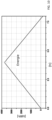
- Example 1 Evolution of pressure and energy in a steam accumulator without incondensable gases.
- 5MWh of energy can be stored in 4 hours with a charge flow rate of 0.58 kg/s, between 4.5 absolute bars and 7.5 absolute bars, i.e. between 50.5 and 94 psi relative ( Figures 2 and 3 ), under conditions of thermodynamic equilibrium between the two liquid and vapor phases.
- the energy can be approximately evaluated in this case by the relation: E ⁇ m L CpL T sat P max ⁇ T sat P min
- Example 2- - Evolution of pressure and energy in a steam accumulator with non-condensable gases.
- Example 2 The same experiment as Example 1 is performed with an injected gas comprising steam and a mass fraction of 2.8% of non-condensable gases.
- the injected gas flow rate is kept identical to Example 1.
- the stored energy is greatly reduced ( Figure 5 ) compared to example 1. Here, it is reduced to 3.34 MWh, i.e. -33% less than in example 1.
- Example 3 Evolution of pressure and energy in a steam accumulator with non-condensable gases.
- Example 2 The same experiment as example 2 is carried out with an injected gas comprising steam and a mass fraction of 2.8% of non-condensable gases.
- the injected gas flow rate is adapted to maintain a charging time of 4 hours.
- the incoming steam flow rate is reduced from 0.58 kg/s to 0.39 kg/s (i.e. less than 33% than in examples 1 and 2) while maintaining the same conditions as in example 1, the charging then stops after 4 hours, and the same amount of energy is stored as in example 2 (3.34MWh) ( Figures 6 And 7 ).
- Example 4 Evolution of pressure and energy in a steam accumulator with non-condensable gases according to the method of the invention.
- the storage capacity is therefore increased from 3.34 MWh to 3.71 MWh, i.e. an 11% increase compared to example 2 or 3.
Landscapes
- Engineering & Computer Science (AREA)
- Mechanical Engineering (AREA)
- General Engineering & Computer Science (AREA)
- Physics & Mathematics (AREA)
- Thermal Sciences (AREA)
- Chemical & Material Sciences (AREA)
- Combustion & Propulsion (AREA)
- Filling Or Discharging Of Gas Storage Vessels (AREA)
Claims (14)
- Verfahren zum Speichern von Wärmeenergie in einem Dampfspeicher, der einen Behälter (1), der eine Flüssigkeit (2) enthält, und einen Gashimmel (3), der über der Flüssigkeit (2) eingerichtet ist, und eine Einspritzvorrichtung (5) von Gas, das in den Behälter (1) eintritt, und eine Vorrichtung zum Ableiten von Gas, das aus dem Behälter (1) austritt, umfasst, wobei das Gas Dampf und mindestens ein nicht kondensierbares Gas umfasst, wobei das Verfahren umfasst:- eine Energieladephase, die eine Gaseinspritzung mit einem ersten Gasdurchsatz mindestens teilweise in die Flüssigkeit, die in dem Behälter (1) des Speichers enthalten ist, durch die Gaseinspritzvorrichtung (5) umfasst, und wobei sich der Dampf des Gases bei Berührung der Flüssigkeit (2), die kälter ist, kondensiert und Energie freisetzt, was die Temperatur der Flüssigkeit (2) erhöht, und- eine Entladephase, die das Öffnen der Ableitungsvorrichtung und das Senken des Drucks in dem Behälter (1) umfasst, was ein Verdampfen der Flüssigkeit (2) bewirkt,dadurch gekennzeichnet, dass das Verfahren außerdem während der Energieladephase eine Ableitung von Gas mit einem zweiten Gasdurchsatz aus dem Behälter (1) des Speichers heraus durch die Gasableitungsvorrichtung (4) umfasst, wobei der erste Gasdurchsatz und der zweite Gasdurchsatz in Abhängigkeit von dem Massenanteil an nicht kondensierbarem Gas in dem eingespritzten Gas gesteuert werden, um eine optimale Energiespeicherung zu erreichen, wobei der zweite Gasdurchsatz geringer als der erste Gasdurchsatz ist.
- Verfahren nach dem vorstehenden Anspruch, wobei die Gasableitung mit einem zweiten Gasdurchsatz im Laufe der Ladephase intermittierend ist.
- Verfahren nach Anspruch 1, wobei die Gasableitung mit einem zweiten Gasdurchsatz im Laufe der Ladephase kontinuierlich ist.
- Verfahren nach einem der vorstehenden Ansprüche, wobei die Gasableitung mit einem zweiten Gasdurchsatz im Laufe der Ladephase intermittierend ausgehend von dem Gashimmel (3) erfolgt.
- Verfahren nach einem der vorstehenden Ansprüche, wobei die Gaseinspritzung mit einem ersten Gasdurchsatz im Laufe der Ladephase kontinuierlich ist.
- Verfahren nach einem der vorstehenden Ansprüche, wobei die Gaseinspritzung mit einem ersten Gasdurchsatz einen Gashauptdurchsatz und einen komplementären Gasdurchsatz umfasst.
- Verfahren nach dem vorstehenden Anspruch, wobei die Gaseinspritzung mit einem komplementären Gasdurchsatz im Laufe der Ladephase intermittierend ist.
- Verfahren nach Anspruch 6, wobei die Gaseinspritzung mit einem komplementären Gasdurchsatz im Laufe der Ladephase kontinuierlich ist.
- Verfahren nach einem der Ansprüche 6 bis 8, wobei die Gaseinspritzung mit einem komplementären Gasdurchsatz in die Flüssigkeit (2), die in dem Behälter (1) enthalten ist, erfolgt.
- Verfahren nach einem der Ansprüche 6 bis 8, wobei die Gaseinspritzung mit einem komplementären Gasdurchsatz in einen Gashimmel (3), der über der Flüssigkeit (2), die in dem Behälter (1) enthalten ist, erfolgt.
- Verfahren nach einem der Ansprüche 6 bis 8, wobei der komplementäre Gasdurchsatz geringer ist als der Hauptgasdurchsatz.
- Verfahren nach einem der vorstehenden Ansprüche 6 bis 8, wobei der zweite Gasdurchsatz höher oder gleich dem komplementären Gasdurchsatz ist.
- Verfahren nach einem der vorstehenden Ansprüche, wobei die Flüssigkeit (2), die in dem Behälter (1) enthalten ist, Wasser ist, und der Dampf des Gases der Wasserdampf ist, der mindestens ein nicht kondensierbares Gas umfasst.
- Dampfspeicher, der dazu angepasst ist, das Verfahren nach Anspruch 1 umzusetzen, der einen Behälter (1) umfasst, der eine Flüssigkeit (2) und einen Gashimmel (3), eine Einspritzvorrichtung (5) von Gas, das in den Behälter (1) eintritt, eine Ableitungsvorrichtung (4) von Gas, das aus dem Behälter (1) austritt, ein Verwaltungsmodul, das einen Rechner und eine Steuereinheit umfasst, die Steuerschieber der Gaseinspritzvorrichtung (5) und der Ableitungsvorrichtung (4) von Gas, das aus dem Behälter (1) austritt, umfasst, dadurch gekennzeichnet, dass das Gas Dampf und mindestens ein nicht kondensierbares Gas umfasst, wobei das Verwaltungsmodul dazu konfiguriert ist, die folgenden Aktionen während der Energieladephase umzusetzen:a) eine Gaseinspritzvorrichtung mit einem ersten Gasdurchsatz mindestens teilweise in die Flüssigkeit, die in den Behälter (1) des Speichers enthalten ist, durch die Gaseinspritzvorrichtung (5), wobei sich der Dampf des Gases bei Berührung mit der Flüssigkeit (2), die kälter ist, kondensiert und Energie freisetzt, was die Temperatur der Flüssigkeit (2) erhöhtb) eine Gasableitung mit einem zweiten Gasdurchsatz aus dem Behälter (1) des Speichers durch die Gasableitungsvorrichtung (4) heraus, wobei der erste Gasdurchsatz und der zweite Gasdurchsatz in Abhängigkeit von dem Massenanteil an nicht kondensierbarem Gas in dem eingespritzten Gas gesteuert werden, um eine optimale Speicherenergie zu erreichen, wobei der zweite Gasdurchsatz geringer ist als der erste Gasdurchsatz,
und das Verwaltungsmodul dazu konfiguriert ist, die folgende Aktion während der Energieentladephase umzusetzenc) das Öffnen der Ableitungsvorrichtung und das Senken des Drucks in dem Behälter (1), die eine Verdampfung der Flüssigkeit (2) bewirken.
Applications Claiming Priority (1)
| Application Number | Priority Date | Filing Date | Title |
|---|---|---|---|
| FR2013972A FR3118097B1 (fr) | 2020-12-22 | 2020-12-22 | Procédé de stockage d'énergie dans un accumulateur de vapeur |
Publications (3)
| Publication Number | Publication Date |
|---|---|
| EP4019745A1 EP4019745A1 (de) | 2022-06-29 |
| EP4019745C0 EP4019745C0 (de) | 2025-02-05 |
| EP4019745B1 true EP4019745B1 (de) | 2025-02-05 |
Family
ID=74759066
Family Applications (1)
| Application Number | Title | Priority Date | Filing Date |
|---|---|---|---|
| EP21216729.0A Active EP4019745B1 (de) | 2020-12-22 | 2021-12-22 | Verfahren zum speichern von energie in einem dampfakkumulator |
Country Status (2)
| Country | Link |
|---|---|
| EP (1) | EP4019745B1 (de) |
| FR (1) | FR3118097B1 (de) |
Family Cites Families (4)
| Publication number | Priority date | Publication date | Assignee | Title |
|---|---|---|---|---|
| JPS60159377A (ja) * | 1984-01-30 | 1985-08-20 | Hitachi Ltd | 太陽熱発電装置 |
| ES2350221B1 (es) * | 2009-06-19 | 2011-10-21 | Abengoa Solar New Technologies, S.A. | Sistema y procedimiento de acumulacion de vapor en tanques para aplicacion solar. |
| EP3081770A1 (de) * | 2015-04-17 | 2016-10-19 | Siemens Aktiengesellschaft | Energiespeichersystem und -verfahren |
| FR3074277B1 (fr) * | 2017-11-28 | 2019-10-25 | Commissariat A L'energie Atomique Et Aux Energies Alternatives | Systeme de stockage thermique (sst) par materiaux a changement de phase (mcp) comprenant un dispositif de controle de la cristallisation |
-
2020
- 2020-12-22 FR FR2013972A patent/FR3118097B1/fr active Active
-
2021
- 2021-12-22 EP EP21216729.0A patent/EP4019745B1/de active Active
Also Published As
| Publication number | Publication date |
|---|---|
| EP4019745C0 (de) | 2025-02-05 |
| EP4019745A1 (de) | 2022-06-29 |
| FR3118097B1 (fr) | 2023-04-14 |
| FR3118097A1 (fr) | 2022-06-24 |
Similar Documents
| Publication | Publication Date | Title |
|---|---|---|
| EP3864336B1 (de) | Verfahren und anlage zur speicherung und verteilung von verflüssigtem wasserstoff | |
| FR3066250B1 (fr) | Dispositif et procede de refroidissement de gaz liquefie et/ou de gaz d'evaporation naturelle de gaz liquefie | |
| EP2288811B1 (de) | Vorrichtung und verfahren zum pumpen einer kryogenen flüssigkeit | |
| FR3034836A1 (fr) | Station et procede de remplissage d'un reservoir avec un gaz carburant | |
| EP3218639A2 (de) | Vorrichtung und verfahren zum kühlen eines flüssiggases | |
| EP3510317B1 (de) | Anlage, verfahren zur lagerung und verflüssigung eines verflüssigten gases und zugehöriges transportfahrzeug | |
| FR2908859A1 (fr) | Procede et station de ravitaillement en hydrogene | |
| EP3102868A2 (de) | Anlage zur bereitstellung und behandlung von kryogener flüssigkeit | |
| WO2018206511A1 (fr) | Dispositif et procede d'alimentation en combustible d'une installation de production d'energie | |
| FR3066249A1 (fr) | Dispositif et procede de refroidissement de gaz liquefie et/ou de gaz d'evaporation naturelle de gaz liquefie | |
| EP4019745B1 (de) | Verfahren zum speichern von energie in einem dampfakkumulator | |
| WO2020193922A1 (fr) | Station de remplissage pour alimenter une pluralité de véhicules avec un gaz contenant de l'hydrogène | |
| FR3111416A1 (fr) | Desurchauffeur de fluide frigorigene sous forme gazeuse et installation mettant en œuvre un cycle frigorifique associee | |
| EP3488139B1 (de) | Modul und system zur druckentlastung eines kryogenen tanks | |
| EP4222366A1 (de) | Gasversorgungssystem für hoch- und niederdruckgasverbrauchsgeräte | |
| FR3162828A1 (fr) | Procédé de pressurisation pour conditionner et distribuer un gaz liquéfié. | |
| WO2024094561A1 (fr) | Procédé de contrôle de la pression intérieure d'un réservoir cryogénique | |
| WO2020109607A1 (fr) | Dispositif de generation de gaz sous forme gazeuse a partir de gaz liquefie | |
| WO2025093827A1 (fr) | Système d'alimentation en gaz d'au moins un appareil consommateur de gaz d'un ouvrage flottant | |
| WO2005105669A1 (fr) | Procédé de liquéfaction du dioxyde de 5 carbone solide | |
| WO2020127365A1 (fr) | Ensemble pour le remplissage d'un réservoir d'oxygène liquide d'un sous-marin et procédé de remplissage associé | |
| FR2897140A1 (fr) | Procede de remplissage d'un conteneur de gaz sous pression | |
| FR3146161A1 (fr) | Système de stockage et de récupération d’énergie par gaz comprimé avec un dispositif de régulation de la pression | |
| WO2025257499A1 (fr) | Procede d'alimentation en gaz d'un appareil consommateur de gaz d'un ouvrage flottant | |
| FR2570478A1 (fr) | Procedes et dispositifs pour condenser et recycler les gaz qui s'evaporent d'une cuve de navire de transport de gaz liquefie et navires comportant ces dispositifs |
Legal Events
| Date | Code | Title | Description |
|---|---|---|---|
| PUAI | Public reference made under article 153(3) epc to a published international application that has entered the european phase |
Free format text: ORIGINAL CODE: 0009012 |
|
| STAA | Information on the status of an ep patent application or granted ep patent |
Free format text: STATUS: REQUEST FOR EXAMINATION WAS MADE |
|
| 17P | Request for examination filed |
Effective date: 20211222 |
|
| AK | Designated contracting states |
Kind code of ref document: A1 Designated state(s): AL AT BE BG CH CY CZ DE DK EE ES FI FR GB GR HR HU IE IS IT LI LT LU LV MC MK MT NL NO PL PT RO RS SE SI SK SM TR |
|
| GRAP | Despatch of communication of intention to grant a patent |
Free format text: ORIGINAL CODE: EPIDOSNIGR1 |
|
| STAA | Information on the status of an ep patent application or granted ep patent |
Free format text: STATUS: GRANT OF PATENT IS INTENDED |
|
| INTG | Intention to grant announced |
Effective date: 20240730 |
|
| RAP3 | Party data changed (applicant data changed or rights of an application transferred) |
Owner name: COMMISSARIAT A L'ENERGIE ATOMIQUE ET AUX ENERGIESALTERNATIVES |
|
| GRAS | Grant fee paid |
Free format text: ORIGINAL CODE: EPIDOSNIGR3 |
|
| GRAA | (expected) grant |
Free format text: ORIGINAL CODE: 0009210 |
|
| STAA | Information on the status of an ep patent application or granted ep patent |
Free format text: STATUS: THE PATENT HAS BEEN GRANTED |
|
| AK | Designated contracting states |
Kind code of ref document: B1 Designated state(s): AL AT BE BG CH CY CZ DE DK EE ES FI FR GB GR HR HU IE IS IT LI LT LU LV MC MK MT NL NO PL PT RO RS SE SI SK SM TR |
|
| REG | Reference to a national code |
Ref country code: GB Ref legal event code: FG4D Free format text: NOT ENGLISH |
|
| REG | Reference to a national code |
Ref country code: CH Ref legal event code: EP |
|
| REG | Reference to a national code |
Ref country code: IE Ref legal event code: FG4D Free format text: LANGUAGE OF EP DOCUMENT: FRENCH |
|
| REG | Reference to a national code |
Ref country code: DE Ref legal event code: R096 Ref document number: 602021025758 Country of ref document: DE |
|
| U01 | Request for unitary effect filed |
Effective date: 20250227 |
|
| U07 | Unitary effect registered |
Designated state(s): AT BE BG DE DK EE FI FR IT LT LU LV MT NL PT RO SE SI Effective date: 20250307 |
|
| PG25 | Lapsed in a contracting state [announced via postgrant information from national office to epo] |
Ref country code: RS Free format text: LAPSE BECAUSE OF FAILURE TO SUBMIT A TRANSLATION OF THE DESCRIPTION OR TO PAY THE FEE WITHIN THE PRESCRIBED TIME-LIMIT Effective date: 20250505 |
|
| PG25 | Lapsed in a contracting state [announced via postgrant information from national office to epo] |
Ref country code: PL Free format text: LAPSE BECAUSE OF FAILURE TO SUBMIT A TRANSLATION OF THE DESCRIPTION OR TO PAY THE FEE WITHIN THE PRESCRIBED TIME-LIMIT Effective date: 20250205 |
|
| PG25 | Lapsed in a contracting state [announced via postgrant information from national office to epo] |
Ref country code: ES Free format text: LAPSE BECAUSE OF FAILURE TO SUBMIT A TRANSLATION OF THE DESCRIPTION OR TO PAY THE FEE WITHIN THE PRESCRIBED TIME-LIMIT Effective date: 20250205 |
|
| PG25 | Lapsed in a contracting state [announced via postgrant information from national office to epo] |
Ref country code: NO Free format text: LAPSE BECAUSE OF FAILURE TO SUBMIT A TRANSLATION OF THE DESCRIPTION OR TO PAY THE FEE WITHIN THE PRESCRIBED TIME-LIMIT Effective date: 20250505 Ref country code: IS Free format text: LAPSE BECAUSE OF FAILURE TO SUBMIT A TRANSLATION OF THE DESCRIPTION OR TO PAY THE FEE WITHIN THE PRESCRIBED TIME-LIMIT Effective date: 20250605 |
|
| PG25 | Lapsed in a contracting state [announced via postgrant information from national office to epo] |
Ref country code: HR Free format text: LAPSE BECAUSE OF FAILURE TO SUBMIT A TRANSLATION OF THE DESCRIPTION OR TO PAY THE FEE WITHIN THE PRESCRIBED TIME-LIMIT Effective date: 20250205 |
|
| PG25 | Lapsed in a contracting state [announced via postgrant information from national office to epo] |
Ref country code: GR Free format text: LAPSE BECAUSE OF FAILURE TO SUBMIT A TRANSLATION OF THE DESCRIPTION OR TO PAY THE FEE WITHIN THE PRESCRIBED TIME-LIMIT Effective date: 20250506 |
|
| PG25 | Lapsed in a contracting state [announced via postgrant information from national office to epo] |
Ref country code: SM Free format text: LAPSE BECAUSE OF FAILURE TO SUBMIT A TRANSLATION OF THE DESCRIPTION OR TO PAY THE FEE WITHIN THE PRESCRIBED TIME-LIMIT Effective date: 20250205 |
|
| PG25 | Lapsed in a contracting state [announced via postgrant information from national office to epo] |
Ref country code: CZ Free format text: LAPSE BECAUSE OF FAILURE TO SUBMIT A TRANSLATION OF THE DESCRIPTION OR TO PAY THE FEE WITHIN THE PRESCRIBED TIME-LIMIT Effective date: 20250205 |
|
| PG25 | Lapsed in a contracting state [announced via postgrant information from national office to epo] |
Ref country code: SK Free format text: LAPSE BECAUSE OF FAILURE TO SUBMIT A TRANSLATION OF THE DESCRIPTION OR TO PAY THE FEE WITHIN THE PRESCRIBED TIME-LIMIT Effective date: 20250205 |
|
| PLBE | No opposition filed within time limit |
Free format text: ORIGINAL CODE: 0009261 |
|
| STAA | Information on the status of an ep patent application or granted ep patent |
Free format text: STATUS: NO OPPOSITION FILED WITHIN TIME LIMIT |
|
| PGFP | Annual fee paid to national office [announced via postgrant information from national office to epo] |
Ref country code: GB Payment date: 20251229 Year of fee payment: 5 |
|
| 26N | No opposition filed |
Effective date: 20251106 |
|
| U20 | Renewal fee for the european patent with unitary effect paid |
Year of fee payment: 5 Effective date: 20251217 |