EP4077144B1 - Behälter, verpackung und verfahren zur herstellung letzterer - Google Patents
Behälter, verpackung und verfahren zur herstellung letzterer Download PDFInfo
- Publication number
- EP4077144B1 EP4077144B1 EP20839143.3A EP20839143A EP4077144B1 EP 4077144 B1 EP4077144 B1 EP 4077144B1 EP 20839143 A EP20839143 A EP 20839143A EP 4077144 B1 EP4077144 B1 EP 4077144B1
- Authority
- EP
- European Patent Office
- Prior art keywords
- container
- sheet
- panel
- hollow
- hollow element
- Prior art date
- Legal status (The legal status is an assumption and is not a legal conclusion. Google has not performed a legal analysis and makes no representation as to the accuracy of the status listed.)
- Active
Links
Images


Classifications
-
- B—PERFORMING OPERATIONS; TRANSPORTING
- B65—CONVEYING; PACKING; STORING; HANDLING THIN OR FILAMENTARY MATERIAL
- B65D—CONTAINERS FOR STORAGE OR TRANSPORT OF ARTICLES OR MATERIALS, e.g. BAGS, BARRELS, BOTTLES, BOXES, CANS, CARTONS, CRATES, DRUMS, JARS, TANKS, HOPPERS, FORWARDING CONTAINERS; ACCESSORIES, CLOSURES, OR FITTINGS THEREFOR; PACKAGING ELEMENTS; PACKAGES
- B65D5/00—Rigid or semi-rigid containers of polygonal cross-section, e.g. boxes, cartons or trays, formed by folding or erecting one or more blanks made of paper
- B65D5/009—Rigid or semi-rigid containers of polygonal cross-section, e.g. boxes, cartons or trays, formed by folding or erecting one or more blanks made of paper the container body comprising a set of interconnected cells, e.g. hinged one to another
-
- B—PERFORMING OPERATIONS; TRANSPORTING
- B65—CONVEYING; PACKING; STORING; HANDLING THIN OR FILAMENTARY MATERIAL
- B65D—CONTAINERS FOR STORAGE OR TRANSPORT OF ARTICLES OR MATERIALS, e.g. BAGS, BARRELS, BOTTLES, BOXES, CANS, CARTONS, CRATES, DRUMS, JARS, TANKS, HOPPERS, FORWARDING CONTAINERS; ACCESSORIES, CLOSURES, OR FITTINGS THEREFOR; PACKAGING ELEMENTS; PACKAGES
- B65D5/00—Rigid or semi-rigid containers of polygonal cross-section, e.g. boxes, cartons or trays, formed by folding or erecting one or more blanks made of paper
- B65D5/20—Rigid or semi-rigid containers of polygonal cross-section, e.g. boxes, cartons or trays, formed by folding or erecting one or more blanks made of paper by folding-up portions connected to a central panel from all sides to form a container body, e.g. of tray-like form
- B65D5/2038—Rigid or semi-rigid containers of polygonal cross-section, e.g. boxes, cartons or trays, formed by folding or erecting one or more blanks made of paper by folding-up portions connected to a central panel from all sides to form a container body, e.g. of tray-like form at least two opposed folded-up portions having a non-rectangular shape
- B65D5/2047—Rigid or semi-rigid containers of polygonal cross-section, e.g. boxes, cartons or trays, formed by folding or erecting one or more blanks made of paper by folding-up portions connected to a central panel from all sides to form a container body, e.g. of tray-like form at least two opposed folded-up portions having a non-rectangular shape trapezoidal, e.g. to form a body with diverging side walls
-
- B—PERFORMING OPERATIONS; TRANSPORTING
- B65—CONVEYING; PACKING; STORING; HANDLING THIN OR FILAMENTARY MATERIAL
- B65D—CONTAINERS FOR STORAGE OR TRANSPORT OF ARTICLES OR MATERIALS, e.g. BAGS, BARRELS, BOTTLES, BOXES, CANS, CARTONS, CRATES, DRUMS, JARS, TANKS, HOPPERS, FORWARDING CONTAINERS; ACCESSORIES, CLOSURES, OR FITTINGS THEREFOR; PACKAGING ELEMENTS; PACKAGES
- B65D77/00—Packages formed by enclosing articles or materials in preformed containers, e.g. boxes, cartons, sacks or bags
- B65D77/003—Articles enclosed in rigid or semi-rigid containers, the whole being wrapped
Definitions
- the object of the present invention is a container of paper material, a process of making the same, as well as a package comprising the container.
- the container and package object of the present invention can be used for housing food type products, e.g., confectionery products, biscuits, crackers, snacks.
- pans used for cooking food products, e.g., as the ones described in the U.S.A. patent application No. US4986432A .
- These pans comprise a perforated sheet of paper material to which a plurality of distinct baking cups are engaged and configured to receive the dough. While the pans enable, due to the presence of distinct baking cups, to house products having a predetermined height, such pans have a complex multi-piece structure negatively weighing on the manufacturing costs and consequently on the product.
- cups of paper material are available on the market which comprise a plurality of distinct seats distanced from each other, each of them being provided of a base and a lateral wall developing away from the base in order to define a cavity housing a food product.
- Such cups are made by stamping a single flat sheet of paper material.
- Such cups due to limitations given by the employed manufacturing process, have a limited vertical extension, preventing the cups from containing products having a determined vertical extension; furthermore, this manufacturing process does not enable to make some shapes, this condition negatively weighs on the flexibility in using the same.
- the U.S.A. patent application No. US4754914A describes instead single seat containers, configured to house a food product; such containers are obtained by folding a single paper sheet material. While the containers described in the U.S.A. patent application No. US4754914A have a structure capable of ensuring to contain products having a substantial vertical development, these are limited by the presence of a single seat and therefore they are provided of different compartments for housing food products. Single seat containers similar to the one described in the U.S.A. patent application No. US4754914A are also described in the following patent applications: US5873220A , DE8612900U1 .
- a first object of the present invention consists of providing a multi-compartment container suitable to enable to house products having a high vertical development; particularly, a goal of the present invention consists of providing a container comprising a plurality of compartments distinct from each other, each of them is suitable to contain one or more products and protect the integrity thereof.
- a further object of the present invention consists of providing a container having a simple and compact structure having also an optimal strength from the structural point of view. It is a further object of the present invention to provide a container which can be easily and reversibly closed after being opened for the first time.
- the term "product” means an article or a composition of articles of any kind.
- the product can be in a solid, liquid or gel state, in other words as two or more of said aggregation states.
- the product can be understood as a package, for example a blister, containing a plurality of articles.
- the product can comprise: drugs, beauty products, dishwasher and washing machine capsules, house cleaning products and laundry cleaning products (e.g., detergents), foodstuff, and cigarettes.
- paper material means paper or paperboard, for example featuring at least 50% by weight, optionally at least 70% by weight of an organic material comprising one or more among cellulose, hemicellulose, lignin, derivatives of lignin.
- the paper material can be a sheet material having a grammage comprised between 100 and 500 g/m 2 .
- the sheet paper material can be coated at least partially by a plastic material coating, for example a film, destined to: reinforce the paper sheet material, define a water and/or humidity barrier.
- the coating can have a thickness varying between 10 ⁇ m and 50 ⁇ m and can be made by one or more of the following materials: LDPE, HDPE, PP, PE.
- blade refers to a semi-finished product of sheet material, for example of paper sheet material, foldable on itself for completing a container.
- the blank can be in a single piece and obtainable by die cutting a single sheet.
- folded configuration of the blank means a configuration in which the blank is folded to form a container.
- sheet material means a material featuring two dimensions, for example the length and width, substantially greater than a third dimension, such as the thickness.
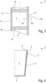
- the reference number 1 generally indicates a container of paper material for housing at least one food product P made by the steps of folding a single flat sheet of paper material.
- the container 1 shown in Fig. 1 comprises a plurality of hollow elements 2 in a substantially prismatic quadrangular shape, each of them can comprise a base 3 featuring a quadrangular shape delimited by a peripheral edge and developing along a horizontal plane, each hollow element 2 comprises at least one lateral wall 4 emerging from the base 3 and defining with this latter a seat 5 configured to receive at least one product P.
- Each lateral wall 4 has a quadrilateral shape, optionally squared, rectangular or trapezoidal one, engaged, on one side, to the peripheral edge of the base 3 and defining, oppositely, a free edge 6 suitable to define an opening configured to allow the introduction and withdrawal of at least one product P from the seat 5.
- the at least one lateral wall 4 has an inclination with respect to the base 3 of the hollow element 2 itself equal to an angle comprised between 90° and 100°, optionally between 91° and 97°, measured inside the seat 5 of the respective hollow element 2.
- the inclination of the lateral walls 4 of each hollow element 2 allows the same to receive inside a further hollow element 2 of a different container 1; consequently, due to the inclination of the lateral walls 4, the container 1 according to the present invention, can be stacked as illustrated in Fig. 2 in order to make easier the storage and transport.
- each hollow element 2 has a distance with respect to the base, which is considered equal to the length of the lateral wall 4, greater than 20 mm, optionally comprised between 20 mm and 70 mm. Moreover, it is useful to note, as shown in the attached figures, that the base 3 and free edge 6 of each hollow element lie on respective planes substantially parallel to each other, in which the minimum distance between said lying plane of the base and free edge define a depth of the seat of each hollow element 2 equal to or greater than 20 mm, optionally comprised between 20 mm and 100 mm.
- the container 1 comprises at least a series of hollow elements 2 defined by at least one first and one second hollow elements 2a, 2b aligned along a predetermined trajectory A, optionally rectilinear, in which at least a lateral wall 4 of the first hollow element 2a is distanced from at least one lateral wall 4 of the second hollow element 2b.
- the container comprises only two hollow elements placed side by side.
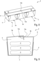
- Figures 1, 2 , 6-9 show a second embodiment of the container 1 comprising three hollow elements 2 aligned along the predetermined trajectory A.
- Figure 2 shows a plurality of containers 1 according to the second embodiment, which are vertically stacked, in which each hollow element 2 of a container is housed inside the seat 5 of a hollow element 2 of an underlying container.
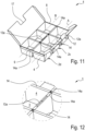
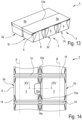
- a third embodiment shown in Figures from 11 to 17, on the contrary refers to a container 1 comprising at least one first and one second series of hollow elements 2 respectively aligned along a first and second trajectories A, B, optionally rectilinear, substantially parallel to each other.
- each series of the container 1 according to the third series comprises a plurality of hollow elements 2 so that the container substantially defines an array of hollow elements 2.
- Figures from 11 to 17 show in a non-limiting way a container comprising only two series of hollow elements, each of them comprises three hollow elements aligned along a predetermined direction; it is not excluded the possibility of providing a greater number of series (in other words greater than two) in which each series comprises a number of hollow elements 2 equal to or greater than two (for example comprised between 2 and 50).
- the hollow elements 2 are engaged with each other in correspondence of at least part of the respective free edges 6.
- the first hollow element 2a can comprise at least one flange 14 extending outside the seat 5 from the free edge 6 of the same first hollow element 2a, joined in one piece to at least to the second hollow element 2b.
- the flange 14 is interposed between the lateral walls 4 respectively of the first and second hollow elements 2a, 2b.
- the lateral wall 4 of the first hollow element 2a is interposed between the flange 14 and base 3 of the same first hollow element 2a.
- the second hollow element 2b comprises also a flange 14 extending outside the seat 5 from the free edge 6 of the same second hollow element 2b, towards the first hollow element 2a, joined in one piece to the flange 14 of the first hollow element 2a.
- the flange 14 of the first and second hollow elements 2a, 2b lies on a plane parallel to the lying plane of the base 3 of each hollow element 2.
- first and second hollow elements 2a, 2b, illustrated in the second embodiment of the container 1 are typical of all the embodiments of the container 1 ; in other words, the features of the first and second hollow elements 2a, 2b are typical of each pair of immediately adjacent hollow elements 2 of the container and are joined in one piece to each other.
- the container 1, according to the third embodiment comprises an intermediate flange 14a which joins in one piece two series of hollow elements 2 placed side by side to each other (see Fig. 11 , for example).
- the container 1 shown in the attached figures further comprises an outer perimetral edge 8, which has a substantially quadrilateral shaped closed profile opposite to the bases 3 of the plurality of hollow elements 2.
- the outer perimetral edge 8 delimits an upper access to the seats 5 of each hollow element 2, which are completely defined inside the same outer perimetral edge 8.
- the outer perimetral edge 8 can be defined by at least part of the free edges 6 of the lateral walls 4 of the plurality of hollow elements 2, developing on a lying plane parallel to the lying plane of the bases of the hollow elements 2.
- the container 1 further comprises at least one panel 9 joined in one piece to at least one segment of the outer perimetral edge 8 of the container 1 and arranged at least partially outside each seat 5 of a hollow element 2.
- each panel 9 can be formed by at least two elementary panels 20 ( Figure 1 ) each of them extends respectively from the free edge 6 of the first and second hollow elements 2a, 2b.
- the elementary panel 20 of the first hollow element 2a can therefore comprise at least one joining portion 21, which is configured to engage, optionally by gluing, a respective joining portion 21 of the elementary panel 20 of the second hollow element 2b, for defining the panel 9.
- the panel 9 is arranged next to a lateral wall 4 of at least one hollow element 2, optionally is engaged with a lateral wall 4; in such configuration, overlapping the panel 9 on at least part of the lateral wall 4 allows to increase the structural rigidity of the container 1.
- the panel 9 extends from the outer perimetral edge 8 towards the bases 3 of the plurality of hollow elements 2 of the container along a predetermined extension direction.
- the container 1 can comprise a plurality of panels 9 extending from each side of the perimetral edge 8 towards the base 3.
- a height of the panel 9 which is lower than a distance present between the free edge 6 and base 3 of each hollow element measured in the same way along the same extension direction.
- the ratio of the height of panel 9 and the lateral wall 4, directly joined in one piece to the panel is lower than 0.75, optionally is lower than 0.5, still more optionally is comprised between 0.45 and 0.2
- the panel 9, according to the first configuration is for example illustrated in Figures 1, 2 and 4 , associated to the container 1 according to the second embodiment; obviously, it is not excluded the provision of the panel 9 as in the first configuration, associated to the container according to the above described first and/or third embodiments.
- the at least one panel 9 is engaged with the outer perimetral edge 8 and is movable with respect to this latter by rotating at least between a first and second operating positions.
- the panel 9 allows the communication between the openings of the hollow elements 2 and the outer environment, in order to define an open condition of the container 1 suitable to enable the withdrawal and insertion products P.
- the panel 9 is arranged at least partially above the openings of the plurality of hollow elements 2, occluding at least partially them, for defining a closed condition of the container suitable to prevent the products P from being withdrawn.
- the panel 9 can comprise at least one first and one second panels 9a, 9b, connected to and emerging from opposite sides of the outer perimetral edge with respect to the predetermined aligning trajectory A of the hollow elements 2.
- the container 1 can comprise at least one panel 9 for each side of the outer perimetral edge 8.
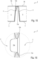
- the first and second panels 9a, 9b are movable between a first operating position, illustrated in Figures 6 and 11 , in which they are configured to enable to insert the products P inside the seats 5 of each hollow element 2 ( Fig. 7 ), and a second operating position in which they are at least partially overlapped on each other and configured to completely occlude the openings of the plurality of hollow elements 2 ( Figures 8 and 13 ).
- the container 1 can comprise only a panel 9 according to the first configuration, as illustrated in Figure 1 for example, or can comprise the panel 9 according to the second configuration (movable panel). It is not excluded the possibility of providing a container 1 comprising at least one panel 9 according to the first configuration and at least one panel 9 according to the second configuration; for example, Figures 6 , 8 , 11 , and 13 illustrate a container 1 comprising the first and second panels 9a, 9b according to the second configuration (movable with respect to the perimetral edge 8) engaged on the opposite sides of the perimetral edge 8 and a further pair of opposite panels 9 according to the first configuration, in other words fixed to a lateral wall 4 of at least one hollow element 2; particularly, the pair of panels 9 fixed to the lateral wall 4 placed side by side to the first and second movable panels 9a, 9b.
- the container 1 can further comprise at least one first and one second coupling portions 12, 13 configured to engagingly cooperate with each other, enabling the panel 9 to remain in the second operating position and therefore to maintain the container 1 in the closed condition.
- the first coupling portion 12 can comprise at least one tab 12a and is stably supported by the at least one panel 9.
- the tab 12a emerges from an outer profile of the panel 9.
- the first coupling portion 12 is supported by the panel 9 according to the second configuration, in other words when the panel 9 is relatively movable with respect to the outer perimetral edge 8 of the container 1.
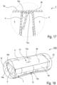
- the first coupling portion 12, particularly the tab 12a can be joined in one piece to the first panel 9a as illustrated in Figures 6 , 11 and 17 , for example.
- the second coupling portion 13 can comprise a slot 13a configured to receive through it the tab 12a and enable to lock the tab.
- the slot 13a can be for example defined on a lateral wall 4 of the container 1 (this condition is not illustrated in the attached figures) or can be defined on at least one panel 9.
- the tab 12a is supported by the first panel 9a while the slot 13a is defined on the second panel 9b, in particular at a central zone of the second panel 9b.
- the slot 13a supported by the second panel 9b is configured to enable, in the second operating position of the first and second panels 9a, 9b, to insert the tab 12a in the first coupling portion 12 inside a seat 5 of a hollow element 2 ( Figure 9 ).
- the second coupling portion 13 is configured to lock the first panel 9a above the second panel 9b in order to keep the container in the closed condition.
- the second coupling portion 13 can be defined on the intermediate flange 14a joining in one piece two series of hollow elements 2 placed side by side.
- the second coupling portion 13 comprises a slot 13a carried by the intermediate flange 14a and configured to enable, in the second operating position of the first and second panels 9a, 9b, to position the tab 12a of the first coupling portion 12, outside the seats 5 of the hollow elements 2 between the lateral walls 4 of hollow elements 2 adjacent to each other and respectively belonging to the first and second series of hollow elements (see Figure 14 , 15 and 16 , for example).
- the second panel 9b can comprise a recess 16 configured to enable the first panel 9a, at least in the second operating position of the first and second panels 9a, 9b, to directly face the second coupling portion 13 carried by the intermediate flange 14a.
- the recess 16 can have a convex profile, optionally opened, configured to enable to arrange the second coupling portion 13 inside the recess 16 itself.
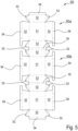
- the blank 50 can have at least one first surface defining, after the step of folding the at least one lateral sheet 52 and central sheet 51, respectively of the first and second sheets 50a, 50b, a surface of the seat 5 of the hollow element 2 suitable to receive a product P, and also a second surface defining, after the same folding step, an outer surface of the container 1.
- the central sheets 51 of the first and second sheets 50a, 50b define the bases 3 of each hollow element 2.
- the central sheets 51, respectively of the first and second sheets 50a, 5b has a polygonal quadrangular shape, wherein from each side of the same quadrangular polygon, emerges at least one lateral sheet 52.
- the central sheets 51 of the first and second sheets 50a, 50b are reciprocally divided by at least one lateral sheet 52 of the first sheet 50a and by a lateral sheet 52 of the second sheet 50b.
- the first sheet 50a can comprise a plurality of lateral sheets 52 emerging from the respective central sheet 51.
- the lateral sheets 52 of the first and second sheets 50a, 50b after the above cited folding steps, define the lateral walls 4 of the hollow elements 2.
- Each lateral sheet 52 of the first and second sheets 50a, 50b is therefore arranged between its central sheet 51 and peripheral sheet 54 respectively of the first and second sheets 50a, 50b, these latter will be better described in the following detailed description.
- the first sheet 50a comprises at least one lateral connecting sheet 53 carried by at least one of the lateral sheets 52 of the first sheet 50a and featuring a triangular shape.
- the lateral connecting sheet 53 can be constrained, optionally by gluing, to an adjacent lateral sheet 52 in order to stably keep the tridimensional configuration of the hollow element 2.
- the first sheet 50a can comprise at least one peripheral sheet 54 joined in one piece to at least one lateral sheet 52 of the first sheet 50a itself, in order to define, after the step of folding this latter, the at least one panel 9 of the container.
- the first sheet 50a can comprise a plurality of peripheral sheets 54 emerging oppositely to the central sheet 51 of the first sheet 50a. Consequently, the process can comprise, after or simultaneously with the step of folding the lateral sheets 52, a step of folding each peripheral sheet 54 of the first sheet 50a with respect to the lateral sheet 52, so that the second surfaces of the peripheral sheet 54 and of the lateral sheet 52 face and are at least partially in contact with each other.
- the process can comprise the step of predisposing a tab 56 carried by at least one peripheral sheet 54 and emerging from a perimetral edge delimiting this latter.
- the tab 56 can be configured to define, after the step of folding the blank, the first coupling portion of the container 1.
- the second sheet 50b can comprise a plurality of lateral sheets 52 emerging from the respective central sheet 51, and also at least one lateral connecting sheet 53 featuring a triangular shape and carried by at least one of the lateral sheets 52 of the second sheet 50b.
- the lateral connecting sheet 53 can be constrained, optionally by gluing, to an adjacent lateral sheet 52 in order to stably keep the hollow element 2 in its tridimensional configuration.
- the second sheet 50b can comprise at least one peripheral sheet 54 joined in one piece to at least one lateral sheet 52 of the same second sheet 50b, for defining, after the step of folding this latter, the at least one panel 9 of the container.
- the process can further comprise the steps of:
- the process further comprises the step of predisposing at least one opening 57 obtained after a step of cutting a peripheral sheet 54 of the second sheet 50b opposite to the peripheral sheet 54 supporting the tab 56.
- the cutting step performed after the step of folding the blank, defines the slot 13a of the second coupling portion 13.
- the blank 50 can comprise at least one central connecting sheet 55 configured to define, after the step of folding the at least one lateral sheet 52, at least part of a flange 14 of the hollow element 2.
- the central element 55 can be delimited by a perimetral edge and is joined in one piece to two lateral sheets 52 respectively of the first and second sheets 50a, 50b along respective opposite segments of the perimetral edge of the connecting sheet 55.
- the blank 50 can further comprise at least one third and fourth sheets 50c, 50d made according respectively to the first and second sheets 50a, 50b of the same blank 50, and also at least one joining sheet 58 configured to join in one piece the first, second, third and fourth sheets 50a, 50b, 50c, 50d to each other along a perimetral edge delimiting the same joining sheet 58.
- the joining sheet 58 comprises a first and second joining sheets 58a, 58b respectively joined in one piece to the first and third sheets 50a, 50c and to the second and fourth sheets 50b, 50d.
- the first joining sheet 58a is joined in one piece to respective lateral sheets 52 of the first and third sheets 50a, 50c along a first segment of the perimetral edge of the joining sheet 58.
- the second joining sheet 58b is joined in one piece to respective lateral sheets 52 of the second and fourth sheets 50b, 50d along a second segment of the perimetral edge of the joining sheet 58, opposite to the first segment, in order to define, after the step of folding each lateral sheet 52, the intermediate flange 14a.
- the at least one joining sheet 58 can comprise an opening 57 obtained after at least one step of cutting this latter, for defining the slot 13a of the second coupling portion 13.
- the process comprises the step of cutting a peripheral sheet 54 of the blank 50 for defining the recess 16.
- the package 100 can comprise at least one case of sheet material, optionally made of at least one among: plastics, aluminum, or paper, featuring a housing compartment 22 having a substantially closed volume, configured to hold the container 1.
- the case 17 comprises at least one end closure portion 18 joined in one piece by a lateral wall 19 for defining a tubular element receiving inside said container 1.
- the at least one end closure portion 18 of the case 17 comprises a first and second end closure portions 18a, 18b opposite to each other and configured to engage each other in order to occlude the housing compartment 22 of the case and to prevent the container 1 from being withdrawn from this latter.
- the container once arranged inside the housing compartment 22, contains at least one product P, optionally of a food type.
- Fig. 18 shows a configuration of the package 100 wherein the container 1 is arranged inside the housing compartment 22 of this latter, featuring the second panel 9b, on which it is defined the second coupling portion 13 in the second operating position, which completely occludes the access to the seats 5 of each hollow element 2.
- the first panel 9a supporting the first coupling portion 12 is arranged in the first operating position placed side by side to the lateral wall 4, configured to increase the structural rigidity of the inside of container 1.
Landscapes
- Engineering & Computer Science (AREA)
- Mechanical Engineering (AREA)
- Cartons (AREA)
Claims (15)
- Behälter (1) zum Unterbringen wenigstens eines Produkts (P), wobei der Behälter (1) eine Mehrzahl hohler Elemente (2) umfasst, welche zusammen in einem Stück verbunden sind, wobei jedes hohle Element (2) aus der Mehrzahl hohler Elemente umfasst:- eine Basis (3),- wenigstens eine laterale Wand (4), welche von der Basis (3) hervortritt und mit dieser einen Sitz (5) definiert, welcher dazu eingerichtet ist, wenigstens ein Produkt (P) aufzunehmen, wobei die laterale Wand (4) wenigstens eine Öffnung definiert, welche durch einen freien Rand (6) begrenzt ist und dazu eingerichtet ist, das Einsetzen und Entnehmen wenigstens eines Produkts (P) von dem Sitz (5) zu ermöglichen,wobei der Behälter (1) durch Falten eines einzelnen flachen Rohlings hergestellt ist, welcher aus einem Papierbogenmaterial hergestellt ist,wobei der Behälter einen äußeren Rand (8) mit einem geschlossenen Profil umfasst, welches entgegengesetzt zu den Basen (3) der Mehrzahl hohler Elemente (2) ist und einen oberen Zugang des Behälters (1) begrenzt, wobei die Sitze der Mehrzahl hohler Elemente innerhalb des äußeren Rands (8) definiert sind,wobei der Behälter ferner wenigstens ein Paneel (9) umfasst, welches mit wenigstens einem Teil des äußeren Rands (8) des Behälters (1) in einem Stück verbunden ist,dadurch gekennzeichnet, dass das Paneel (9) an einem Bereich, welcher zu dem perimetraler äußeren Rand (8) eigen und beabstandet ist, wenigstens an der lateralen Wand (4) fixiert ist, optional durch Kleben.
- Behälter nach dem vorhergehenden Anspruch, umfassend wenigstens ein erstes hohles Element (2a) aus der Mehrzahl hohler Elemente (2), welches wenigstens einen Kragen (14) umfasst, welcher sich beginnend von dem freien Rand (6) der lateralen Wand (4) des ersten hohlen Elements (2a) außerhalb des Sitzes (5) erstreckt, wobei der Kragen (14) des ersten hohlen Elements (2a) in einem Stück mit wenigstens einem zweiten hohlen Element (2b) aus der Mehrzahl hohler Elemente (2) verbunden ist, welches benachbart zu dem ersten hohlen Element (2a) ist, optional wobei die laterale Wand (4) des ersten hohlen Elements (2a) zwischen dem Kragen und der Basis des gleichen ersten Elements (2a) eingefügt ist,wobei das zweite hohle Element (2b) einen Kragen (14) umfasst, welcher sich beginnend von dem freien Rand (6) der lateralen Wand (4) des zweiten hohlen Elements (2b) außerhalb des Sitzes (5) erstreckt und sich dem ersten hohlen Element (2a) annähert,wobei der Kragen (14) des ersten hohlen Elements (2a) in einem Stück mit dem Kragen (14) des zweiten hohlen Elements (2b) verbunden ist, optional wobei die laterale Wand des zweiten hohlen Elements (2b) zwischen den Kragen und die Basis des zweiten hohlen Elements (2b) eingefügt ist.
- Behälter nach dem vorhergehenden Anspruch, wobei das Paneel (9) wenigstens teilweise außerhalb des Sitzes (5) der Mehrzahl hohler Elemente (2) angeordnet ist.
- Behälter nach dem vorhergehenden Anspruch, wobei das Paneel (9) an wenigstens einer lateralen Wand (4) des wenigstens einen hohlen Elements (2) wenigstens teilweise, optional direkt, eingeschränkt ist.
- Behälter nach Anspruch 1 oder 4, wobei das Paneel (9) auf einer Ebene liegt, welche im Wesentlichen parallel zu einer liegenden Ebene der lateralen Wand (4) ist, welche das Paneel direkt trägt, optional mit welcher das Paneel in einem Stück direkt verbunden ist.
- Behälter nach einem der Ansprüche 1, 4 oder 5, wobei das wenigstens eine Paneel (9) stabil an der wenigstens einen lateralen Wand (4), welche das Paneel (9) direkt trägt, mittels Klebabschnitten fixiert ist.
- Behälter nach einem der Ansprüche 1, 4 bis 6, wobei wenigstens ein Abschnitt des wenigstens einen Paneels (9) von dem äußeren Rand (8) beabstandet ist und, optional mittels Klebstoff, an der lateralen Wand (4) eingeschränkt ist, welche das Paneel (9) direkt trägt.
- Behälter nach einem der Ansprüche 1, 4 bis 7, wobei das wenigstens eine Paneel (9) an der wenigstens einen lateralen Wand (4), welche das Paneel (9) direkt trägt, an zwei Bereichen stabil eingeschränkt ist:- an dem äußeren Rand (8);- an einem im Wesentlichen zentralen Bereich des Paneels (9).
- Behälter nach einem der Ansprüche 1, 4 bis 8, wobei das Paneel (9) wenigstens ein erstes und ein zweites Paneel (9a, 9b) umfasst, welche an entgegengesetzten Seiten des äußeren Rands (8) verbunden sind.
- Behälter nach einem der Ansprüche 1, 4 bis 9, wobei der äußere Rand (8) eine vierseitige Form aufweist, wobei der Behälter (1) wenigstens ein Paneel (9) für jede Seite des umlaufenden äußeren Rands (8) umfasst.
- Behälter nach einem der Ansprüche 1, 4 bis 10, wobei das Paneel (9) an einer Mehrzahl von lateralen Wänden (4) des Behälters fixiert ist, optional an zwei oder mehr lateralen Wänden benachbarter hohler Elemente (2).
- Behälter nach einem der vorhergehenden Ansprüche, wobei der Behälter wenigstens eine erste und eine zweite Reihe hohler Elemente (2) umfasst, wobei jede davon eine Mehrzahl hohler Elemente umfasst, wobei:- die hohlen Elemente der ersten Reihe entlang einer ersten Trajektorie (A) aligniert sind, optional geradlinig,- die hohlen Elemente der zweiten Reihe entlang einer zweiten Trajektorie (B) aligniert sind, optional geradlinig,wobei die erste und die zweite Trajektorie im Wesentlichen parallel zueinander sind,wobei der Behälter einen Zwischenkragen (14a) umfasst, welcher an den freien Rändern der hohlen Element der ersten und der zweiten Reihe in einem Stück mit der Mehrzahl hohler Elemente der ersten und der zweiten Reihe hohler Elemente verbunden ist.
- Verfahren eines Herstellens eines Behälters (1) nach einem der vorhergehenden Ansprüche, wobei das Verfahren wenigstens die folgenden Schritte umfasst:- Voranordnen eines flachen Rohlings (50) aus Papierbogenmaterial, umfassend wenigstens einen ersten Bogen und einen zweiten Bogen (50a, 50b), wobei jeder aus diesem ersten und zweiten Bogen (50a, 50b) wenigstens umfasst:- einen zentralen Bogen (51),- einen lateralen Bogen (52), welcher in einem Stück mit dem zentralen Bogen (51) verbunden ist und von einem Umfangsrand des letzteren hervortritt,wobei der erste und der zweite Bogen (50a, 50b) an deren jeweiligen lateralen Bögen (52) in einem Stück verbunden sind,- Falten wenigstens eines lateralen Bogens (52) und des zentralen Bogens (51) des ersten Bogens (50a) relativ zueinander, um ein hohles Element (2) zu definieren,- Falten wenigstens eines lateralen Bogens (52) und des zentralen Bogens (51) des zweiten Bogens (50b) relativ zueinander, um ein zusätzliches hohles Element (2) zu definieren,wobei der erste und der zweite Bogen (50a, 50b) wenigstens einen umlaufenden Bogen (54) umfassen, welcher in einem Stück mit wenigstens einem lateralen Bogen (52) jeweils des ersten und des zweiten Bogens (50a, 50b) verbunden ist,wobei, nachfolgend auf den Schritt eines Faltens des ersten und des zweiten Bogens (50a, 50b), der umlaufende Bogen das wenigstens eine Paneel (9) des Behälters definiert.
- Verfahren nach dem vorhergehenden Anspruch, wobei die jeweiligen zentralen Bogen (51) des ersten und des zweiten Bogens (59a, 59b) eine vierseitige Form aufweisen, wobei, beginnend von jeder Seite des vierseitigen Polygons, wenigstens ein lateraler Bogen (52) hervortritt,
wobei die zentralen Bögen (51) des ersten und des zweiten Bogens (59a, 59b) mittels eines lateralen Bogens (52) des ersten Bogens (50a) und eines lateralen Bogens (52) des zweiten Bogens (50b) voneinander getrennt sind. - Packung (100), umfassend- wenigstens ein Gehäuse (17) aus Bogenmaterial, welches einen Unterbringungsraum (20) mit einem im Wesentlichen geschlossenen Volumen umfasst,- wenigstens einen Behälter (1) nach einem der vorhergehenden Ansprüche von 1 bis 12,- wenigstens ein Produkt, zum Beispiel vom Lebensmitteltyp, welches innerhalb wenigstens eines Sitzes wenigstens eines hohlen Elements (2) des Behälters angeordnet ist,wobei der Behälter (1), welcher das wenigstens eine Produkt (P) trägt, innerhalb des Unterbringungsraums des Gehäuses (17) angeordnet ist.
Priority Applications (1)
| Application Number | Priority Date | Filing Date | Title |
|---|---|---|---|
| EP24202257.2A EP4488189A1 (de) | 2019-12-17 | 2020-12-16 | Behälter, verpackung und verfahren zu deren herstellung |
Applications Claiming Priority (2)
| Application Number | Priority Date | Filing Date | Title |
|---|---|---|---|
| IT102019000024322A IT201900024322A1 (it) | 2019-12-17 | 2019-12-17 | Contenitore, confezione e procedimento per la realizzazione di questi ultimi |
| PCT/IB2020/062017 WO2021124141A1 (en) | 2019-12-17 | 2020-12-16 | Container, package and process of making these latter |
Related Child Applications (1)
| Application Number | Title | Priority Date | Filing Date |
|---|---|---|---|
| EP24202257.2A Division EP4488189A1 (de) | 2019-12-17 | 2020-12-16 | Behälter, verpackung und verfahren zu deren herstellung |
Publications (3)
| Publication Number | Publication Date |
|---|---|
| EP4077144A1 EP4077144A1 (de) | 2022-10-26 |
| EP4077144C0 EP4077144C0 (de) | 2024-09-25 |
| EP4077144B1 true EP4077144B1 (de) | 2024-09-25 |
Family
ID=70155100
Family Applications (2)
| Application Number | Title | Priority Date | Filing Date |
|---|---|---|---|
| EP24202257.2A Pending EP4488189A1 (de) | 2019-12-17 | 2020-12-16 | Behälter, verpackung und verfahren zu deren herstellung |
| EP20839143.3A Active EP4077144B1 (de) | 2019-12-17 | 2020-12-16 | Behälter, verpackung und verfahren zur herstellung letzterer |
Family Applications Before (1)
| Application Number | Title | Priority Date | Filing Date |
|---|---|---|---|
| EP24202257.2A Pending EP4488189A1 (de) | 2019-12-17 | 2020-12-16 | Behälter, verpackung und verfahren zu deren herstellung |
Country Status (5)
| Country | Link |
|---|---|
| US (1) | US12179969B2 (de) |
| EP (2) | EP4488189A1 (de) |
| ES (1) | ES2996938T3 (de) |
| IT (1) | IT201900024322A1 (de) |
| WO (1) | WO2021124141A1 (de) |
Families Citing this family (2)
| Publication number | Priority date | Publication date | Assignee | Title |
|---|---|---|---|---|
| WO2023225270A1 (en) * | 2022-05-20 | 2023-11-23 | Graphic Packaging International, Llc | Tray with separable features |
| USD1092203S1 (en) | 2023-05-19 | 2025-09-09 | Graphic Packaging International, Llc | Tray |
Family Cites Families (14)
| Publication number | Priority date | Publication date | Assignee | Title |
|---|---|---|---|---|
| IT207419Z2 (it) | 1986-04-30 | 1988-01-18 | Novacart Spa | Struttura di teglia per la cottura e la distribuzione di dolci o alimenti in genere. |
| DE8612900U1 (de) * | 1986-05-12 | 1987-09-10 | Unilever N.V., Rotterdam | Verpackung für tiefgefrorene Nahrungsmittel |
| US4754914A (en) | 1986-09-26 | 1988-07-05 | Rock-Tenn Company | Package for wrapping food or other articles |
| US4944451A (en) * | 1989-12-06 | 1990-07-31 | Westvaco Corporation | Compartmented flanged tray |
| US5383596A (en) * | 1991-11-22 | 1995-01-24 | Gulf States Paper Corporation | Plural tray compartment carton package |
| US5356070A (en) * | 1993-01-27 | 1994-10-18 | Westvaco Corporation | Partitioned paperboard food tray |
| US5873220A (en) * | 1997-01-16 | 1999-02-23 | Westvaco Corporation | Method for producing a self-locking, paperboard pail-like container and product thereof |
| US6505769B2 (en) * | 2001-04-19 | 2003-01-14 | Caraustar Custom Packaging | Partial web in tray corners |
| US7017798B2 (en) * | 2003-03-07 | 2006-03-28 | Tin Inc. | Food-transport tray |
| US8459536B2 (en) * | 2007-05-30 | 2013-06-11 | Arvco Container Corporation | Nesting catering tray container |
| DE102010042855A1 (de) * | 2010-10-25 | 2012-04-26 | Colordruck Baiersbronn W. Mack Gmbh & Co. Kg | Faltschachtel und Faltschachtelzuschnitt |
| US12391456B2 (en) * | 2016-07-22 | 2025-08-19 | Graphic Packaging International, Llc | Container with liner |
| AU2018413295B2 (en) * | 2018-03-16 | 2022-01-27 | Graphic Packaging International, Llc | Container with liner |
| HRP20211504T1 (hr) * | 2018-04-18 | 2021-12-24 | Packable B.V. | Preklopna ambalaža za hermetičko pakiranje hrane |
-
2019
- 2019-12-17 IT IT102019000024322A patent/IT201900024322A1/it unknown
-
2020
- 2020-12-16 EP EP24202257.2A patent/EP4488189A1/de active Pending
- 2020-12-16 EP EP20839143.3A patent/EP4077144B1/de active Active
- 2020-12-16 US US17/785,858 patent/US12179969B2/en active Active
- 2020-12-16 WO PCT/IB2020/062017 patent/WO2021124141A1/en not_active Ceased
- 2020-12-16 ES ES20839143T patent/ES2996938T3/es active Active
Also Published As
| Publication number | Publication date |
|---|---|
| EP4077144C0 (de) | 2024-09-25 |
| EP4488189A1 (de) | 2025-01-08 |
| ES2996938T3 (en) | 2025-02-13 |
| US12179969B2 (en) | 2024-12-31 |
| EP4077144A1 (de) | 2022-10-26 |
| IT201900024322A1 (it) | 2021-06-17 |
| US20230348128A1 (en) | 2023-11-02 |
| WO2021124141A1 (en) | 2021-06-24 |
Similar Documents
| Publication | Publication Date | Title |
|---|---|---|
| US8844798B2 (en) | Dual reclosable dispenser carton | |
| US8251276B2 (en) | Octagon-shaped food-transport container | |
| US3596822A (en) | Package structure | |
| EP2148827B1 (de) | Verpackungseinheit | |
| EP4077144B1 (de) | Behälter, verpackung und verfahren zur herstellung letzterer | |
| FI20176011A1 (fi) | Pinottava tuotepakkaus ja menetelmä sen valmistamiseksi sekä tuotepakkausaihio | |
| FI97359B (fi) | Pakkaustarjotin | |
| RU2606573C9 (ru) | Коробка и упаковка, содержащая коробку, помещенную между четырьмя стаканчиками | |
| SE542046C2 (en) | A lid component provided with stacking members and a paperboard packaging container provided with such lid component | |
| CA2339500A1 (en) | Articulable container | |
| US11230403B2 (en) | Carrier and blank therefor | |
| JP7487106B2 (ja) | カートン及びブランク | |
| US20230219733A1 (en) | Carrier | |
| US11312552B2 (en) | Article carrier and blank therefor | |
| EP2690025B1 (de) | Lebensmittelverpackung und Verfahren zur Herstellung einer Lebensmittelverpackung | |
| EP3279112B1 (de) | Aufrechtstehende schale, verpackung und verfahren | |
| US20220144478A1 (en) | Nested Paper Tray Having Divided Compartments | |
| EP3030496B1 (de) | Starrer behälter | |
| RU2734638C1 (ru) | Упаковка и заготовка для нее | |
| US7850064B2 (en) | Food-transport container with monoplanar multipart end panels | |
| AU2017411384A1 (en) | Packaging and blank therefor | |
| NL2010446C2 (en) | Food container. | |
| JP2002145352A (ja) | 即席麺用包装容器 | |
| CN104411592A (zh) | 盒子以及包括四个杯子之间的盒子的包装 |
Legal Events
| Date | Code | Title | Description |
|---|---|---|---|
| STAA | Information on the status of an ep patent application or granted ep patent |
Free format text: STATUS: UNKNOWN |
|
| STAA | Information on the status of an ep patent application or granted ep patent |
Free format text: STATUS: THE INTERNATIONAL PUBLICATION HAS BEEN MADE |
|
| PUAI | Public reference made under article 153(3) epc to a published international application that has entered the european phase |
Free format text: ORIGINAL CODE: 0009012 |
|
| STAA | Information on the status of an ep patent application or granted ep patent |
Free format text: STATUS: REQUEST FOR EXAMINATION WAS MADE |
|
| 17P | Request for examination filed |
Effective date: 20220614 |
|
| AK | Designated contracting states |
Kind code of ref document: A1 Designated state(s): AL AT BE BG CH CY CZ DE DK EE ES FI FR GB GR HR HU IE IS IT LI LT LU LV MC MK MT NL NO PL PT RO RS SE SI SK SM TR |
|
| DAV | Request for validation of the european patent (deleted) | ||
| DAX | Request for extension of the european patent (deleted) | ||
| GRAP | Despatch of communication of intention to grant a patent |
Free format text: ORIGINAL CODE: EPIDOSNIGR1 |
|
| STAA | Information on the status of an ep patent application or granted ep patent |
Free format text: STATUS: GRANT OF PATENT IS INTENDED |
|
| INTG | Intention to grant announced |
Effective date: 20240419 |
|
| GRAS | Grant fee paid |
Free format text: ORIGINAL CODE: EPIDOSNIGR3 |
|
| GRAA | (expected) grant |
Free format text: ORIGINAL CODE: 0009210 |
|
| STAA | Information on the status of an ep patent application or granted ep patent |
Free format text: STATUS: THE PATENT HAS BEEN GRANTED |
|
| AK | Designated contracting states |
Kind code of ref document: B1 Designated state(s): AL AT BE BG CH CY CZ DE DK EE ES FI FR GB GR HR HU IE IS IT LI LT LU LV MC MK MT NL NO PL PT RO RS SE SI SK SM TR |
|
| REG | Reference to a national code |
Ref country code: GB Ref legal event code: FG4D |
|
| REG | Reference to a national code |
Ref country code: CH Ref legal event code: EP |
|
| REG | Reference to a national code |
Ref country code: DE Ref legal event code: R096 Ref document number: 602020038451 Country of ref document: DE |
|
| REG | Reference to a national code |
Ref country code: IE Ref legal event code: FG4D |
|
| U01 | Request for unitary effect filed |
Effective date: 20240927 |
|
| U07 | Unitary effect registered |
Designated state(s): AT BE BG DE DK EE FI FR IT LT LU LV MT NL PT RO SE SI Effective date: 20241030 |
|
| PG25 | Lapsed in a contracting state [announced via postgrant information from national office to epo] |
Ref country code: NO Free format text: LAPSE BECAUSE OF FAILURE TO SUBMIT A TRANSLATION OF THE DESCRIPTION OR TO PAY THE FEE WITHIN THE PRESCRIBED TIME-LIMIT Effective date: 20241225 |
|
| PG25 | Lapsed in a contracting state [announced via postgrant information from national office to epo] |
Ref country code: GR Free format text: LAPSE BECAUSE OF FAILURE TO SUBMIT A TRANSLATION OF THE DESCRIPTION OR TO PAY THE FEE WITHIN THE PRESCRIBED TIME-LIMIT Effective date: 20241226 |
|
| PG25 | Lapsed in a contracting state [announced via postgrant information from national office to epo] |
Ref country code: RS Free format text: LAPSE BECAUSE OF FAILURE TO SUBMIT A TRANSLATION OF THE DESCRIPTION OR TO PAY THE FEE WITHIN THE PRESCRIBED TIME-LIMIT Effective date: 20241225 |
|
| U20 | Renewal fee for the european patent with unitary effect paid |
Year of fee payment: 5 Effective date: 20241225 |
|
| PG25 | Lapsed in a contracting state [announced via postgrant information from national office to epo] |
Ref country code: RS Free format text: LAPSE BECAUSE OF FAILURE TO SUBMIT A TRANSLATION OF THE DESCRIPTION OR TO PAY THE FEE WITHIN THE PRESCRIBED TIME-LIMIT Effective date: 20241225 Ref country code: NO Free format text: LAPSE BECAUSE OF FAILURE TO SUBMIT A TRANSLATION OF THE DESCRIPTION OR TO PAY THE FEE WITHIN THE PRESCRIBED TIME-LIMIT Effective date: 20241225 Ref country code: GR Free format text: LAPSE BECAUSE OF FAILURE TO SUBMIT A TRANSLATION OF THE DESCRIPTION OR TO PAY THE FEE WITHIN THE PRESCRIBED TIME-LIMIT Effective date: 20241226 |
|
| REG | Reference to a national code |
Ref country code: ES Ref legal event code: FG2A Ref document number: 2996938 Country of ref document: ES Kind code of ref document: T3 Effective date: 20250213 |
|
| PG25 | Lapsed in a contracting state [announced via postgrant information from national office to epo] |
Ref country code: IS Free format text: LAPSE BECAUSE OF FAILURE TO SUBMIT A TRANSLATION OF THE DESCRIPTION OR TO PAY THE FEE WITHIN THE PRESCRIBED TIME-LIMIT Effective date: 20250125 |
|
| PG25 | Lapsed in a contracting state [announced via postgrant information from national office to epo] |
Ref country code: SM Free format text: LAPSE BECAUSE OF FAILURE TO SUBMIT A TRANSLATION OF THE DESCRIPTION OR TO PAY THE FEE WITHIN THE PRESCRIBED TIME-LIMIT Effective date: 20240925 |
|
| PGFP | Annual fee paid to national office [announced via postgrant information from national office to epo] |
Ref country code: ES Payment date: 20250114 Year of fee payment: 5 |
|
| PG25 | Lapsed in a contracting state [announced via postgrant information from national office to epo] |
Ref country code: PL Free format text: LAPSE BECAUSE OF FAILURE TO SUBMIT A TRANSLATION OF THE DESCRIPTION OR TO PAY THE FEE WITHIN THE PRESCRIBED TIME-LIMIT Effective date: 20240925 Ref country code: CZ Free format text: LAPSE BECAUSE OF FAILURE TO SUBMIT A TRANSLATION OF THE DESCRIPTION OR TO PAY THE FEE WITHIN THE PRESCRIBED TIME-LIMIT Effective date: 20240925 |
|
| PG25 | Lapsed in a contracting state [announced via postgrant information from national office to epo] |
Ref country code: SK Free format text: LAPSE BECAUSE OF FAILURE TO SUBMIT A TRANSLATION OF THE DESCRIPTION OR TO PAY THE FEE WITHIN THE PRESCRIBED TIME-LIMIT Effective date: 20240925 |
|
| PG25 | Lapsed in a contracting state [announced via postgrant information from national office to epo] |
Ref country code: MC Free format text: LAPSE BECAUSE OF FAILURE TO SUBMIT A TRANSLATION OF THE DESCRIPTION OR TO PAY THE FEE WITHIN THE PRESCRIBED TIME-LIMIT Effective date: 20240925 |
|
| REG | Reference to a national code |
Ref country code: CH Ref legal event code: PL |
|
| PLBE | No opposition filed within time limit |
Free format text: ORIGINAL CODE: 0009261 |
|
| STAA | Information on the status of an ep patent application or granted ep patent |
Free format text: STATUS: NO OPPOSITION FILED WITHIN TIME LIMIT |
|
| 26N | No opposition filed |
Effective date: 20250626 |
|
| PG25 | Lapsed in a contracting state [announced via postgrant information from national office to epo] |
Ref country code: CH Free format text: LAPSE BECAUSE OF NON-PAYMENT OF DUE FEES Effective date: 20241231 |
|
| PG25 | Lapsed in a contracting state [announced via postgrant information from national office to epo] |
Ref country code: IE Free format text: LAPSE BECAUSE OF NON-PAYMENT OF DUE FEES Effective date: 20241216 |
|
| PGFP | Annual fee paid to national office [announced via postgrant information from national office to epo] |
Ref country code: GB Payment date: 20251223 Year of fee payment: 6 |
|
| PG25 | Lapsed in a contracting state [announced via postgrant information from national office to epo] |
Ref country code: HR Free format text: LAPSE BECAUSE OF FAILURE TO SUBMIT A TRANSLATION OF THE DESCRIPTION OR TO PAY THE FEE WITHIN THE PRESCRIBED TIME-LIMIT Effective date: 20240925 |
|
| U20 | Renewal fee for the european patent with unitary effect paid |
Year of fee payment: 6 Effective date: 20251223 |