EP4077053B1 - Systems for loudspeaker enclosure integration - Google Patents
Systems for loudspeaker enclosure integration Download PDFInfo
- Publication number
- EP4077053B1 EP4077053B1 EP19956359.4A EP19956359A EP4077053B1 EP 4077053 B1 EP4077053 B1 EP 4077053B1 EP 19956359 A EP19956359 A EP 19956359A EP 4077053 B1 EP4077053 B1 EP 4077053B1
- Authority
- EP
- European Patent Office
- Prior art keywords
- coupling unit
- loudspeaker
- panel
- loudspeaker enclosure
- vehicle door
- Prior art date
- Legal status (The legal status is an assumption and is not a legal conclusion. Google has not performed a legal analysis and makes no representation as to the accuracy of the status listed.)
- Active
Links
Images


Classifications
-
- B—PERFORMING OPERATIONS; TRANSPORTING
- B60—VEHICLES IN GENERAL
- B60J—WINDOWS, WINDSCREENS, NON-FIXED ROOFS, DOORS, OR SIMILAR DEVICES FOR VEHICLES; REMOVABLE EXTERNAL PROTECTIVE COVERINGS SPECIALLY ADAPTED FOR VEHICLES
- B60J5/00—Doors
- B60J5/04—Doors arranged at the vehicle sides
- B60J5/0468—Fixation or mounting means specific for door components
-
- H—ELECTRICITY
- H04—ELECTRIC COMMUNICATION TECHNIQUE
- H04R—LOUDSPEAKERS, MICROPHONES, GRAMOPHONE PICK-UPS OR LIKE ACOUSTIC ELECTROMECHANICAL TRANSDUCERS; ELECTRIC HEARING AIDS; PUBLIC ADDRESS SYSTEMS
- H04R1/00—Details of transducers, loudspeakers or microphones
- H04R1/20—Arrangements for obtaining desired frequency or directional characteristics
- H04R1/22—Arrangements for obtaining desired frequency or directional characteristics for obtaining desired frequency characteristic only
- H04R1/28—Transducer mountings or enclosures modified by provision of mechanical or acoustic impedances, e.g. resonator, damping means
- H04R1/2869—Reduction of undesired resonances, i.e. standing waves within enclosure, or of undesired vibrations, i.e. of the enclosure itself
- H04R1/2892—Mountings or supports for transducers
- H04R1/2896—Mountings or supports for transducers for loudspeaker transducers
-
- B—PERFORMING OPERATIONS; TRANSPORTING
- B60—VEHICLES IN GENERAL
- B60R—VEHICLES, VEHICLE FITTINGS, OR VEHICLE PARTS, NOT OTHERWISE PROVIDED FOR
- B60R11/00—Arrangements for holding or mounting articles, not otherwise provided for
- B60R11/02—Arrangements for holding or mounting articles, not otherwise provided for for radio sets, television sets, telephones, or the like; Arrangement of controls thereof
- B60R11/0217—Arrangements for holding or mounting articles, not otherwise provided for for radio sets, television sets, telephones, or the like; Arrangement of controls thereof for loud-speakers
-
- H—ELECTRICITY
- H04—ELECTRIC COMMUNICATION TECHNIQUE
- H04R—LOUDSPEAKERS, MICROPHONES, GRAMOPHONE PICK-UPS OR LIKE ACOUSTIC ELECTROMECHANICAL TRANSDUCERS; ELECTRIC HEARING AIDS; PUBLIC ADDRESS SYSTEMS
- H04R1/00—Details of transducers, loudspeakers or microphones
- H04R1/02—Casings; Cabinets ; Supports therefor; Mountings therein
- H04R1/025—Arrangements for fixing loudspeaker transducers, e.g. in a box, furniture
-
- B—PERFORMING OPERATIONS; TRANSPORTING
- B60—VEHICLES IN GENERAL
- B60J—WINDOWS, WINDSCREENS, NON-FIXED ROOFS, DOORS, OR SIMILAR DEVICES FOR VEHICLES; REMOVABLE EXTERNAL PROTECTIVE COVERINGS SPECIALLY ADAPTED FOR VEHICLES
- B60J5/00—Doors
- B60J5/04—Doors arranged at the vehicle sides
- B60J5/0412—Lower door structure
- B60J5/0413—Inner panel, e.g. characterised by carrying components
-
- B—PERFORMING OPERATIONS; TRANSPORTING
- B60—VEHICLES IN GENERAL
- B60J—WINDOWS, WINDSCREENS, NON-FIXED ROOFS, DOORS, OR SIMILAR DEVICES FOR VEHICLES; REMOVABLE EXTERNAL PROTECTIVE COVERINGS SPECIALLY ADAPTED FOR VEHICLES
- B60J5/00—Doors
- B60J5/04—Doors arranged at the vehicle sides
- B60J5/042—Reinforcement elements
- B60J5/0422—Elongated type elements, e.g. beams, cables, belts or wires
-
- B—PERFORMING OPERATIONS; TRANSPORTING
- B60—VEHICLES IN GENERAL
- B60R—VEHICLES, VEHICLE FITTINGS, OR VEHICLE PARTS, NOT OTHERWISE PROVIDED FOR
- B60R11/00—Arrangements for holding or mounting articles, not otherwise provided for
- B60R2011/0001—Arrangements for holding or mounting articles, not otherwise provided for characterised by position
- B60R2011/0003—Arrangements for holding or mounting articles, not otherwise provided for characterised by position inside the vehicle
- B60R2011/0019—Side or rear panels
- B60R2011/0021—Doors
-
- H—ELECTRICITY
- H04—ELECTRIC COMMUNICATION TECHNIQUE
- H04R—LOUDSPEAKERS, MICROPHONES, GRAMOPHONE PICK-UPS OR LIKE ACOUSTIC ELECTROMECHANICAL TRANSDUCERS; ELECTRIC HEARING AIDS; PUBLIC ADDRESS SYSTEMS
- H04R2499/00—Aspects covered by H04R or H04S not otherwise provided for in their subgroups
- H04R2499/10—General applications
- H04R2499/13—Acoustic transducers and sound field adaptation in vehicles
Definitions
- Embodiments of the subject matter disclosed herein relate to the integration of a loudspeaker enclosure into a vehicle.
- Document US 5 736 689 A discloses a system for mounting an audio speaker within an automobile door, in which a bridge is mounted on and extends from a door interior support panel, and has an integral platform spaced from the support panel and surrounding a speaker opening.
- the body of the audio speaker is received within the bridge speaker opening, and mounting flange tabs on the speaker radially project from the speaker body and are releasably secured to the bridge platform.
- An exterior trim panel has a lip that surrounds a speaker opening in the trim panel.
- the trim panel lip is removably secured to the platform radially outwardly of the speaker, such that the trim panel and the speaker are removably secured to the platform independently of each other.
- a grill is removably secured to the trim panel overlying and enclosing the speaker opening in trim panel, and thus covering both the bridge platform and the speaker.
- Document WO 2019/202661 Al discloses a speaker system including a first panel which is an outer panel of a door, a second panel which is provided on the passenger compartment side of the vehicle door and has an opening for sound emission, and the first panel and the second panel.
- a third panel provided between the two, a speaker unit that overlaps with the opening in a plan view from the passenger compartment along the central axis and emits sound toward the passenger compartment, and the speaker unit and the first.
- a sound absorbing material is provided so as to be superposed on a portion corresponding to the antinode of the acoustic particle velocity in the standing wave generated between the panel and the panel.
- Document JP H11 151989 A discloses a structure for mounting a door speaker on an automobile door such as a front door, a rear door, and a back door.
- Loudspeaker enclosures are typically mounted to the inner panels of vehicle doors using fasteners. These inner panels are comprised of a thin sheet of metal without much structure. As such, when the fastened loudspeaker is in use, a lateral load may be imposed on the inner panel causing it to oscillate inward and outward. These oscillations increase the amount of vehicle buzz, squeak, and rattle (BSR) which may concern customers, decrease overall customer satisfaction with the vehicle, and increase warranty claims.
- BSR vehicle buzz, squeak, and rattle
- a vehicle door comprises an interior panel and an exterior panel defining a hollow space, a crossbar member extending through the hollow space in the vehicle door and the crossbar member fixedly attached to an inner face of the exterior panel, a loudspeaker enclosure housing a loudspeaker and mounted to the interior panel of the vehicle door, a first coupling unit fixedly attached to the loudspeaker enclosure, and a second coupling unit fixedly attached to the crossbar member, wherein the second coupling unit is secured to the first coupling unit.
- a loudspeaker system may comprise a loudspeaker and a loudspeaker enclosure configured to house the loudspeaker, the loudspeaker enclosure mountable to an interior panel of a vehicle door.
- the loudspeaker system may further comprise a coupling unit extending from the loudspeaker enclosure and configured to secure the loudspeaker enclosure to a structural component of the vehicle door positioned away from the interior panel, wherein the structural component of the vehicle door comprises a crossbar member extending through a hollow space in the vehicle door defined by the interior panel and an exterior panel of the vehicle door.
- a system for securing a loudspeaker system may comprise a loudspeaker and a loudspeaker enclosure housing the loudspeaker.
- the system may comprise a first coupling unit fixedly attachable to a rear surface of the loudspeaker enclosure, wherein the loudspeaker enclosure is mounted to an interior panel of a vehicle door, and a second coupling unit fixedly attachable to at least one component of the vehicle door positioned away from the interior panel, wherein the second coupling unit is coupleable to the first coupling unit to dampen vibrations of the interior panel when the loudspeaker produces sound, wherein the at least one component of the vehicle door comprises a crossbar member extending through a hollow space in the vehicle door defined by the interior panel and an exterior panel of the vehicle door.
- Most commercial vehicles are designed to include an audio system that may enable users to listen to audio output from a radio, global positioning system (GPS), compact discs (CDs), digital versatile discs (DVDs), cassette tapes, and/or media (e.g., videos, MP3s) streaming from a multimedia device (e.g., a smart phone, tablet).
- the vehicle audio system includes a loudspeaker housed within a loudspeaker enclosure, with the loudspeaker enclosure typically mounted to an inner panel of a vehicle door system, as depicted in FIGS. 1 and 2 .
- the loudspeaker converts electrical signals from the audio system into audible sound, with conversion involving the generation and regulation of vibrational energy by loudspeaker components.
- This vibrational energy may be inadvertently transferred to the inner panel of the vehicle door to which the loudspeaker enclosure is mounted, causing it to oscillate, move, or flex. Movement of the inner panel of the vehicle door induced by loudspeaker use, increases the amount of vehicle buzz, squeak, and rattle (BSR) which may be concerning or annoying to customers, lead to a perceived lack of vehicle quality, decrease overall satisfaction with the vehicle, and increase warranty claims.
- BSR vehicle buzz, squeak, and rattle
- a loudspeaker enclosure may include a first coupling unit extending therefrom to couple to a second coupling unit.
- the second coupling unit is fixed to a structural component such as a crossbar member.
- a set of reference axes 120 are provided for comparison between views shown, indicating a y-axis, a z-axis, and an x-axis.
- the z-axis may be parallel with a direction of gravity, with the x and y axes defining the horizontal plane.
- FIG. 1 a block diagram of a door system 100 with a loudspeaker enclosure 112 integrated according to the embodiments disclosed herein is illustrated.
- the door system 100 may be included, as an illustrative and non-limiting example, as part of a vehicle system (not shown) in which door system 100 may be used to enter and exit the vehicle system.
- door system 100 may be included in the vehicle system using hinge hardware so that door system 100 is attached on a fixed rotatable axis that allows the door system 100 to pivot between a closed position (e.g., a user may not enter the vehicle system) and an open position (e.g., an opening is formed between door system 100 and the vehicle system and a user may enter the vehicle system through the formed opening).
- a closed position e.g., a user may not enter the vehicle system
- an open position e.g., an opening is formed between door system 100 and the vehicle system and a user may enter the vehicle system through the formed opening.
- the door system 100 may be included in a pick-up truck, sedan, sport utility vehicle, crane, helicopter, airplane, forklift, dump truck, and so on.
- door system 100 may be mounted on or suspended from a track within the vehicle system so that door system 100 may slide along a horizontal axis between an open position that allows users to enter the vehicle system and a closed position.
- the door system 100 may be included in a tram, train, bus, van, subway cars, and the like.
- the door system 100 include a loudspeaker 110 that is communicatively coupled to a sound system (not shown) configured to provide electrical audio signals to the loudspeaker 110, which the loudspeaker 110 converts to audible sound by vibrating responsive to the electrical audio signals, for example.
- the loudspeaker 110 may comprise a cone (not shown) surrounding and attached to an electromagnetic coil (not shown), with the electromagnetic coil positioned around or inside of a permanent magnet (not shown).
- electrical signals from the audio source or sound system may pass through the electromagnetic coil of the loudspeaker 110 causing the electromagnetic coil to be continuously attracted and repelled (e.g., vibrate back and forth) from the permanent magnet.
- the cone to which the electromagnetic coil is attached amplifies these vibrations thereby pumping sound waves into the surrounding air allowing users to listen to audio media within the vehicle system.
- Some of the vibrational energy generated from the loudspeaker 110 when the sound system is in use may be transferred from the loudspeaker enclosure 112 to the structural component of a door system 100 to which the loudspeaker enclosure 112 is fastened or mounted.
- use of the loudspeaker 110 may cause an inner door panel, such as the first panel 104, to which the loudspeaker enclosure 112 is mounted to oscillate which, in turn, may cause other vehicle components in contact with the inner door panel to vibrate thereby contributing to overall vehicle BSR.
- systems are provided for damping vibrational energy transfer from the loudspeaker 110 and the loudspeaker enclosure 112 to other structural components of vehicle door system 100 when the sound system is in use. It should be appreciated that the systems provided herein for damping the oscillations of a loudspeaker enclosure may be implemented in other structural systems than a vehicle door without departing from the scope of the present disclosure.
- the door components 102 of the door system 100 include a first panel 104, a second panel 106, and a crossbar member 108.
- the first panel 104 and the second panel 106 form inner and outer surfaces of a vehicle door comprising the door system 100, and may be positioned relative to each other to form a hollow cavity 180 or space between the first panel 104 and the second panel 106.
- the first panel 104 may comprise thin sheet metal, for example, with a limited degree of structure.
- the first panel 104 includes an inner face 122 which faces inwardly relative to an associated vehicle and an outer face 124 which faces outwardly relative to an associated vehicle.
- the first panel 104 may include apertures that allow for access to other door components 102 during vehicle assembly and/or the direct or indirect attachment of other functional components, such as a window (not shown), an inside door release handle (not shown) on the inner face 122, a loudspeaker enclosure 112 on inner face 122, and so on.
- the first panel 104 may be generally parallel to the second panel 106 as depicted.
- the second panel 106 includes an inner face 126 which faces inwardly relative to an associated vehicle and an outer face 128 which faces outwardly relative to an associated vehicle.
- the outer face 128 of the second panel 106 may comprise the exterior surface of a door comprising the door system 100.
- the second panel 106 may comprise a sheet of metal formed into patterns and/or curves, with the overall formed structure increasing the rigidity of the second panel 106.
- the second panel 106 may have one or more reinforcement panels fixedly attached to the inner face 126.
- the second panel 106 may have a combination of reinforcement panels and crossbar members, such as the crossbar member 108, fixedly attached to the inner face 126.
- the second panel 106 may have one or more crossbar members, such as the crossbar member 108, fixedly attached to the inner face 126.
- an outer face 130 of the crossbar member 108 may be welded, bolted, or otherwise suitably fastened to the inner face 126 of second panel 106.
- the crossbar member 108 may comprise a passive safety device designed to protect vehicle occupants from side impacts. For example, during a vehicle crash, the crossbar member 108 may absorb the energy created during the collision thereby protecting occupants from side impact.
- the crossbar member 108 may be comprised of high strength grade steel, stainless steel, titanium, aluminum, or another suitable material sufficient to increase the stiffness of the vehicle door and distribute the energy from an impact.
- the crossbar member 108 may span the length of a vehicle door and be fastened halfway between a bottom surface (not shown) and a midpoint (not shown) of the second panel 106 along the y-axis.
- the door system 100 may include multiple crossbar members.
- the door system 100 may have a second crossbar member spanning the midsection of second panel 106 along the y-axis.
- the first panel 104 may include apertures for inserting and connecting additional functional components such as a loudspeaker enclosure 112 which houses at least one loudspeaker 110. At least a portion of the loudspeaker enclosure 112 may be contoured to accommodate the shape of a window (not shown) within the door system 100 when the window is rolled all the way down (e.g., when the window is at its lowest setting).
- the loudspeaker enclosure 112 may have apertures that are complimentary to additional apertures in the first panel 104 so that fasteners (e.g., bolts/nuts, torque-locking fasteners) may be inserted to connect the two components when the loudspeaker enclosure 112 has been inserted and the apertures are aligned.
- the loudspeaker enclosure 112 may be epoxy glued or otherwise suitably attached to the first panel 104 after insertion through a complimentary aperture on inner face 122.
- the loudspeaker 110 may introduce or cause BSR during sound system use.
- inner vehicle door panels such as the first panel 104
- the loudspeaker 110 is being continually re-designed with thinner materials to decrease vehicle weight, thereby improving overall fuel economy, handling, braking time, and so on.
- loudspeakers with more powerful subwoofers are being integrated into vehicles.
- the limited structure and slender design of the inner door panel or first panel 104 to which the loudspeaker enclosure 112 is fastened are not enough to prevent the first panel 104 from moving or flexing in response to the lateral energy emitted by the loudspeaker 110.
- the inner door panel 104 may oscillate which, in turn, may cause other functional components of the door system 100 directly or indirectly connected to the inner door panel 104 (e.g. a window, a lock actuator, an interior door handle) to move or vibrate, thereby causing an increase in the BSR of the vehicle.
- the first panel 104 may flex or vibrate when the loudspeaker 110 is in use which, in turn, may cause other components of the door system 100 to shake or vibrate.
- a first coupling unit 114 may be attached, fastened, coupled to, or built into to a rear surface 136 of the loudspeaker enclosure 112.
- the relative positioning of the first coupling unit 114 on the loudspeaker enclosure 112 may be such that the first coupling unit 114 does not disrupt the contoured edge of the loudspeaker enclosure 112 that accommodates the window of the door system 100 when the window is at its lowest setting (e.g., when the window is rolled all the way down).
- the first coupling unit 114 may extend from the loudspeaker enclosure 112 away from loudspeaker 110 (e.g., laterally opposite to the direction from which sound is emitted from loudspeaker 110) and into the hollow space 180 within door system 100.
- the first coupling unit 114 may then be coupled to a second coupling unit 116 via a fastener 118.
- the fastener 118 may comprise a bolt system, rivet, inseparable snap, or any other suitable means to securely fix or fasten the first coupling unit 114 to the second coupling unit 116.
- the first coupling unit 114 may be secured to the second coupling unit 116 without the use of a fastener 118.
- the first coupling unit 114 may directly interlock with the second coupling unit 118 using a series of complimentary recesses and projections.
- the first coupling unit 114 may be hooked to the second coupling unit 118.
- the first coupling unit 114 may be welded, epoxy glued, or soldered to the second coupling unit 118.
- the second coupling unit 116 is fixedly attached to a component of the door system 100 positioned away from the first panel 104.
- the second coupling unit 116 may be attached, fastened, coupled to, or built into the inner face 132 of the crossbar member 108.
- the loudspeaker enclosure 112 may also be coupled to the crossbar member 108.
- the first panel 104 may be stiffened and the vibrational energy resulting from loudspeaker use dampened.
- the lateral energy emitted by the loudspeaker 110 may be at least partially absorbed by the crossbar member 108.
- BSR associated with loudspeaker use may be eliminated or significantly decreased.
- coupling the loudspeaker enclosure 112 to the crossbar member 108 to reduce BSR makes use of current vehicle design as loudspeakers are typically positioned low and close to the front of a vehicle within a door system 100 (for example, as shown in FIG. 2 ) to improve acoustics.
- Crossbar members such as the crossbar member 108 are a required vehicle safety standard, with the lowest crossbar member typically located behind the loudspeaker enclosure 112.
- the loudspeaker enclosure 112 may be coupled to an additional or alternative structural component of the door system 100.
- the loudspeaker enclosure 112 may be coupled to the second panel 106 of the door system 100.
- the loudspeaker enclosure 112 may be coupled to the crossbar member 108 as well as the second panel 106 of the door system 100.
- the first coupling unit 114 may include a plurality of coupling points so that the second coupling unit 116 may be secured to the first coupling unit 114 and a third coupling unit (not shown) may also be secured to the first coupling unit 114.
- the second coupling unit 116 may be fixedly attached to the crossbar member 108 and the third coupling unit may be fixedly attached to the second panel 106 of the door system 100 or to another component of the door system 100.
- two or more coupling units including the first coupling unit 114 may extend from the speaker enclosure 112 and be secured to complimentary coupling units including the second coupling unit 116 located on different structural components of the vehicle door system 100.
- FIG. 2 shows a perspective pictorial view of a vehicle door system 200 for a vehicle door 220 including a loudspeaker enclosure 212 securely integrated into the vehicle door 220 according to an embodiment.
- the door system 200 comprises a first panel 204 and a second panel 206, similar to the first panel 104 and the second panel 106 of the door system 100 described hereinabove.
- the loudspeaker enclosure 212 comprises a housing for at least partially enclosing and supporting a loudspeaker 210.
- the first panel 204 includes an inner face 222 which faces inwardly relative to an associated vehicle and an outer face (not shown) which faces outwardly relative to an associated vehicle.
- the first panel 204 may include several apertures such as first aperture 226, second aperture 228, and a third aperture (not visible) through which the loudspeaker enclosure 212 housing a loudspeaker 210 may be inserted.
- the first aperture 226 and the second aperture 228 may be used to directly and/or indirectly attach or couple other components of door system 200 (e.g., a window 240, an inner door handle) as well as for enabling access to the hollow space 280 between the first panel 204 and the second panel 206.
- the loudspeaker enclosure 212 may be fastened to the inner face 222 of the first panel 204 using a plurality of mounting points including a first mounting point 214, a second mounting point 216, and a third mounting point 218.
- the mounting points of the loudspeaker enclosure 212 may comprise openings that align with complimentary/corresponding apertures on the first panel 204 (not shown). Once the openings and apertures are aligned, the loudspeaker enclosure 212 may be fastened to the inner face 222 of the first panel 204 using torque-locking fasteners, bolts/nuts, rivets, or another suitable means. In some embodiments, the loudspeaker enclosure 212 may include more or less than three mounting points.
- the loudspeaker enclosure 212 may not have mounting points and may be attached to the door inner panel 204 by other suitable means (e.g., epoxy glued).
- vibrational energy may be transferred to the first panel 204 from the loudspeaker enclosure 212 when the loudspeaker 210 is in use.
- vibration of the first panel 204 may cause other components of door system 200 directly and/or indirectly attached or otherwise coupled to the first panel 204 to vibrate, leading to an increase in vehicle BSR.
- the door system 200 includes a second panel 206.
- An outer face (not shown) of the second panel 206 may comprise the external surface of the vehicle door 220.
- a first crossbar member 208 and a second crossbar member 209 may be fixedly attached to an inner face 224 of the second panel 206.
- First crossbar member 208 and second crossbar member 209 may be welded, bolted, or otherwise suitably secured to second panel 206.
- the second panel 206 may have also have reinforcement panels (not shown) fixedly attached to the inner face 224.
- the second panel 206 may have only one crossbar member fixedly attached to the inner face 224 (e.g., only the first crossbar member 208 may be welded onto the inner face 224 of the second panel 206).
- the door system 200 may have more than two crossbar members.
- the loudspeaker enclosure 212 may be coupled to at least or at most one of the crossbar members 208 and 209 according to the methods described herein.
- the loudspeaker enclosure 212 may be coupled to the first crossbar member 208 using coupling units.
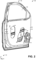
- FIG. 3 shows a cross-sectional side pictorial view of a portion 300 of the vehicle door 220 including the loudspeaker enclosure 212.
- a first coupling unit 302 is attached to or built in to a rear surface 306 of the loudspeaker enclosure 212.
- An example of a first coupling unit 302 is described further herein with regard to FIG. 4 .
- a second coupling unit 304 is attached to or built in to an inner face 310 of the first crossbar member 208. Examples of how the second coupling unit 304 may be fixedly attached to the crossbar member 208 are described further herein with regard to FIGS. 6 and 7 .
- the second coupling unit 304 is configured to complement the first coupling unit 302 such that the first coupling unit 302 and the second coupling unit 304 may be securely coupled.
- the first coupling unit 302 is securely attached or coupled to the second coupling unit 304 via a fastener 308.
- the fastener 308 may be a bolt system, rivet, or another suitable means to securely couple or fasten the first coupling unit 302 to the second coupling unit 304.
- the loudspeaker enclosure 212 may be positioned higher within the vehicle door 220 (relative to the z-axis) so that the speaker enclosure 212 may be securely coupled to the second crossbar member 209 via the first coupling unit 302 and a coupling unit (not shown) similar to the second coupling unit 304 and fixedly attached (e.g., welded, bolted) to the second crossbar member 209 using a fastener similar to the fastener 308.
- the loudspeaker enclosure 212 may be coupled, via coupling units such as the coupling unit 302 and the coupling unit 304, to both the first crossbar member 208 and the second crossbar member 209.
- Such an arrangement may dampen vibrations caused by the loudspeaker 210 in the lateral direction, or along the x-axis, as well as vibrations with y-axis and/or z-axis components.
- the rear surface 306 of loudspeaker enclosure 212 may include a contour 312 that accommodates a window, such as the window 240, of the vehicle door 220 when the window 240 is rolled all the way down.
- the relative positioning of the first coupling unit 302 when fastened to or integrated within the loudspeaker enclosure 212 may be such that the first coupling unit 302 does not disrupt contour 312 and, thus, may not impede window function.
- the first coupling unit 302 may extend laterally (e.g., along the x-axis) from the rear surface 306 of the loudspeaker enclosure 212 into the hollow space 280 within the vehicle door 220. In some embodiments, the first coupling unit 302 may extend from a bottom surface 314 of the loudspeaker enclosure 212 into the hollow space 280 within the vehicle door 220.
- FIG. 4 shows an enlarged rear perspective view 400 of an example loudspeaker enclosure 212 with an example first coupling unit 402.
- the first coupling unit 402 may comprise the first coupling unit 302 described hereinabove with regard to FIGS. 2 and 3 as well as the first coupling unit 114 described hereinabove with regard to FIG. 1 .
- the first coupling unit 402 extends outwards from the rear surface 436 of the loudspeaker enclosure 212.
- the first coupling unit 402 comprises a first section 403 and a second section 404.
- the first section 403 and the second section 404 may be identical in terms of size, shape, and geometry.
- the first section 403 and the second section 404 may be shaped with two angled side edges that curve in towards a rounded, pointed front edge, with each angled side edge further connected to a back edge with minimal curvature.
- the first section 403 and the second section 404 of the first coupling unit 402 may not be identical in terms of size, shape, and geometry.
- first section 403 may be longer than the second section 404
- second section 404 may be a different shape than a first section 403, and so on.
- first coupling unit 402 may take on a different overall shape and construction than depicted in FIG. 4 to accommodate for variation among vehicle door panels and loudspeaker enclosure designs.
- the first coupling unit 402 may be square shaped, triangular, branched/Y shaped, and so on.
- the first section 403 may be coupled to the second section 404 by a plurality of spacers attached at a perpendicular angle to the inner facing surfaces (with respect to the overall structure of the first coupling unit 402) of the first section 403 and the second section 404.
- the plurality of spacers may include a first spacer 414, a second spacer 416, and a third spacer 418, with a first side of each spacer attached to an inner face 420 of the second section 404 and a second side of each spacer attached to an inner face (not visible) of the first section 403.
- the plurality of spacers may be arranged so that an opening or chamber is formed between each adjacent spacer.
- the first coupling unit 402 may further include a first hole 410 in the first section 403 and a second hole 412 in the second section 404, with the first hole 410 aligned with the second hole 412 with respect to the z-axis.
- the first section 403 may additionally include a first groove 406 and a second groove 408.
- the first hole 410, the second hole 412, the first groove 406, and the second groove 408 as well as the overall geometry of the first coupling unit 402 may be designed to interact with a second coupling unit such as the second coupling unit 304, so that the first coupling unit 402 may be securely attached to the second coupling unit 304 via a coupling or fastener (e.g., fastener 308 of FIG. 3 ).
- the first coupling unit 402 may be inserted into a second coupling unit 304 and be secured to the second coupling unit 304 via the fastener 308. In some embodiments, the first coupling unit 402 may interlock with the second coupling unit 304 without the use of the fastener 308 after the first coupling unit 402 is inserted into the second coupling unit 304. In some embodiments, the first coupling unit 402 may be another structural component (e.g., a bracket, a hook) designed to interact and be securely attached to the second coupling unit 304 with or without the use of the fastener 308.
- FIG. 4 further depicts a mounting point 488 similar to the third mounting point 218 described hereinabove with regard to FIG. 2 .
- the loudspeaker enclosure 212 may include additional such mounting points to secure the loudspeaker enclosure 212 to a door panel such as the first panel 204.
- FIG. 5 shows a rear perspective view 500 of the loudspeaker enclosure 212 that includes the first coupling unit 402 as well as a second coupling unit 504 that may be implemented as the second coupling unit 304 or 116 described hereinabove.
- the second coupling unit 504 may comprise an intermediate bracket that may interface with first coupling unit 402 and a structural component of the door system (e.g., the first crossbar member 208, the second crossbar member 209, the second panel 206, and so on).
- the second coupling unit 504 may not be an intermediate bracket and may be another type of coupling device (e.g., a hook, a clasp) that may interlock or be securely attached to the first coupling unit 402 and the structural component of the door system.
- the second coupling unit 504 may be generally M-shaped, and comprised of a first leg 512 and a second leg (not shown). The first leg 512 and the second leg may be inserted into complementary openings/chambers within the first coupling unit 402 formed between the plurality of spacers (e.g., first spacer 414, a second spacer 416) that adjoin the first section 403 and the second section 404 of the first coupling unit 402.
- first leg 512 may be inserted into the first coupling unit 402 via the opening formed between the second spacer 416 and the third spacer 418.
- the underside of a middle portion 514 of the second coupling unit 504 may also include a first ridge and a second ridge (not visible) that, respectively, fit into the first groove 406 and the second groove 408 of first coupling unit 402 when second coupling unit 504 is inserted into first coupling unit 402.
- the middle portion 514 of the second coupling unit 504 may include a hole 516 that is complementary in size, shape, and geometry to the first hole 410 in the first section 403 and the second hole 412 in the second section 404 of the first coupling unit 402.
- a hole 516 that is complementary in size, shape, and geometry to the first hole 410 in the first section 403 and the second hole 412 in the second section 404 of the first coupling unit 402.
- the formed slot may be used to securely attach the first coupling unit 402 to the second coupling unit 504 via a coupling or fastener (e.g., a bolt system, a clamp) which may be inserted through or attached to the formed slot.
- the first coupling unit 402 may be securely attached to the second coupling unit 504 at different distances relative to the door system based on the amount of face-sharing contact between the second coupling unit 504 and the first coupling unit 402.
- the second coupling unit 504 may be fully or partially inserted into the first coupling unit 402, thereby changing the length of the formed slot between the first coupling unit 402 and the second coupling unit 504 and, thus, the amount of options for coupling placement.
- the second coupling unit 504 may be fully inserted into the first coupling unit 402 when the loudspeaker enclosure 212 is close to the structural component of the door system to which the loudspeaker enclosure 212 is to be coupled.
- the second coupling unit 504 may be partially inserted into the first coupling unit 402 when the loudspeaker enclosure 212 is at a greater distance to the structural component of the door system to which the loudspeaker enclosure 212 is to be coupled than in the example above.
- the formed slot may account for space variations that may occur between the loudspeaker enclosure 212 and the structural component of the door system to which the loudspeaker enclosure 212 is to be coupled, as further described with respect to FIG. 6 .
- FIGS. 6 and 7 illustrate how a loudspeaker enclosure such as the loudspeaker enclosure 212 may be coupled to a component of a door system.
- FIG. 6 shows a top pictorial view 600 of the loudspeaker enclosure 212 secured to a crossbar member 608, which may comprise the crossbar member 208, according to an embodiment.
- the crossbar member 608 may be designed for the integration of the second coupling unit 504, with a portion of the crossbar member 608 specifically shaped to accommodate the structure of the second coupling unit 504 as shown.
- the second coupling unit 504 may be built into a front side 610 of the crossbar member 608 or may be attached via suitable means (e.g., bolts/nuts, welding, soldering, and so on).
- first leg 502 and a second leg 602 of the second coupling unit 504 may be inserted into the first coupling unit 402 as previously described.
- the second coupling unit 504 may be inserted into the first coupling unit 402 until hole 506 is partially or fully aligned with the first hole 410 and the second hole 412 of the first coupling unit 402.
- the partial or full alignment of hole 506 with the first hole 410 and the second hole 412 may be such that a fastener 604 may be inserted through the opening/slot formed by aligning all three holes.
- the fastener 604 may be a bolt system, rivet, inseparable snap, or another suitable fastener that allows for the second coupling unit 504 to be securely attached to the first coupling unit 402.
- the fastener 604 may be inserted at any point within the opening/slot formed by aligning all three holes.
- the relative positioning of the first coupling unit 402, with respect to the second coupling unit 504 may be adjusted to account for distance variations (e.g., due to cross vehicle build variation and different loudspeaker enclosure designs) that may occur between the loudspeaker enclosure 212 and the structural component of the door system to which the loudspeaker enclosure 212 may be coupled.
- FIG. 7 shows a top pictorial view 700 of the loudspeaker enclosure 212 secured to a crossbar member 708, which may comprise the crossbar member 208 described hereinabove, via a first coupling unit 402 and a second coupling unit 704.
- the second coupling unit 704 may is configured to be directly attached to a front side 710 of the crossbar member 708 by suitable means (e.g., bolts/nuts, welding, etc.). The second coupling unit 704 may then be coupled to the first coupling unit 402 as previously described via the fastener 604.
- the loudspeaker enclosure 212 may be coupled to a door outer panel (e.g., second panel 206) as described.
- the second coupling unit 304 may be integrated into the design and manufacture of the outer panel or the second coupling unit 304 may be attached to the outer panel via suitable means (e.g., bolted, welded, etc.).
- the second coupling unit 304 may then be coupled to the first coupling unit 302 which may be fixedly coupled or integrated into the loudspeaker enclosure 212.
- suitable means e.g., bolted, welded, etc.
- the loudspeaker enclosure 212 may be coupled to more than one structure of the door system.
- the loudspeaker enclosure 212 may include multiple coupling units that may be coupled to corresponding coupling units located on multiple door structures (e.g., the loudspeaker enclosure 212 may have a first coupling unit that couples to a corresponding coupling unit on a crossbar member and a second coupling unit that couples to a corresponding coupling unit on an outer door panel).
- the loudspeaker enclosure 212 may include a first coupling unit with multiple pairs of holes (e.g., a first pair may include the first hole 410 and the second hole 412), with each hole pair coupled to a different second coupling unit (e.g., both a second coupling unit on a crossbar member and a second coupling unit on a door outer panel may be simultaneously coupled to a first coupling unit of a loudspeaker enclosure).
- a first coupling unit with multiple pairs of holes (e.g., a first pair may include the first hole 410 and the second hole 412), with each hole pair coupled to a different second coupling unit (e.g., both a second coupling unit on a crossbar member and a second coupling unit on a door outer panel may be simultaneously coupled to a first coupling unit of a loudspeaker enclosure).
- a system for a vehicle door comprises a loudspeaker enclosure housing a loudspeaker and mounted to an interior panel of the vehicle door, a first coupling unit fixedly attached to the loudspeaker enclosure, and a second coupling unit fixedly attached to a component of the vehicle door away from the interior panel, wherein the second coupling unit is secured to the first coupling unit.
- the component of the vehicle door comprises an exterior panel of the vehicle door.
- the component of the vehicle door comprises a crossbar member extending through a hollow space in the vehicle door defined by the interior panel and an exterior panel of the vehicle door.
- the second coupling unit is secured to the first coupling using a fastener.
- the loudspeaker is configured to generate sound by vibrating in a lateral direction, wherein the first coupling unit extends from the loudspeaker enclosure in the lateral direction and is secured to the second coupling unit along the lateral direction to dampen vibrations of the interior panel caused by vibrations of the loudspeaker.
- the first coupling unit is fixedly attached to a rear side of the loudspeaker enclosure adjacent to a contoured surface of the loudspeaker enclosure, and the contoured surface of the loudspeaker enclosure is contoured to accommodate a window of the vehicle door when the window is lowered to a lowest position.
- the first coupling unit includes a first hole
- the second coupling unit includes a second hole
- the first coupling unit and the second coupling unit are in face-sharing contact with the first hole and the second hole at least partially aligned to form a coupling slot.
- the system further comprises a fastener extending through the coupling slot to secure the first coupling unit to the second coupling unit.
- a size of the coupling slot varies with the extent of face-sharing contact between the second coupling unit and the first coupling unit.
- a loudspeaker system comprises a loudspeaker, a loudspeaker enclosure configured to house the loudspeaker, the loudspeaker enclosure mountable to an interior panel of a vehicle door, and a coupling unit extending from the loudspeaker enclosure and configured to secure the loudspeaker enclosure to a structural component of the vehicle door positioned away from the interior panel.
- the coupling unit is coupleable to a second coupling unit extending from the structural component to secure the loudspeaker enclosure.
- the loudspeaker emits sound in a lateral direction, and the loudspeaker enclosure is secured to the structural component of the vehicle door in the lateral direction.
- the coupling unit includes a first hole, the second coupling unit includes a second hole, and the coupling unit is coupleable to the second coupling unit when the coupling unit and the second coupling unit are in face-sharing contact and the first hole is at least partially aligned with the second hole.
- the loudspeaker system further comprises a fastener extending through the first hole and the second hole to securely couple the coupling unit to the second coupling unit.
- the first hole is stadium-shaped or oval-shaped and the second hole is stadium-shaped or oval-shaped, and the coupling unit is coupleable to the second coupling unit when the first hole is at least partially aligned with the second hole to produce at least a circular slot for the fastener to extend therethrough.
- the component of the vehicle door comprises one of an exterior panel of the vehicle door, or a crossbar member extending through a hollow space defined by the interior panel and the exterior panel.
- a system for securing a loudspeaker system comprising a loudspeaker and a loudspeaker enclosure housing the loudspeaker.
- the system comprises a first coupling unit fixedly attachable to a rear surface of the loudspeaker enclosure, wherein the loudspeaker enclosure is mounted to an interior panel of a vehicle door, and a second coupling unit fixedly attachable to at least one component of the vehicle door positioned away from the interior panel, wherein the second coupling unit is coupleable to the first coupling unit to dampen vibrations of the interior panel when the loudspeaker produces sound.
- the first coupling unit includes a first hole
- the second coupling unit includes a second hole
- the first coupling unit is coupleable to the second coupling unit when the first coupling unit and the second coupling unit are in face-sharing contact and the first hole is at least partially aligned with the second hole.
- the system further comprises a fastener that extends through the first hole and the second hole to secure the first coupling unit to the second coupling unit.
- the at least one component comprises one or more of a crossbar member and an exterior panel of the vehicle door positioned opposite to the interior panel.
Landscapes
- Engineering & Computer Science (AREA)
- Mechanical Engineering (AREA)
- Physics & Mathematics (AREA)
- Acoustics & Sound (AREA)
- Signal Processing (AREA)
- Health & Medical Sciences (AREA)
- Otolaryngology (AREA)
- Fittings On The Vehicle Exterior For Carrying Loads, And Devices For Holding Or Mounting Articles (AREA)
Description
- Embodiments of the subject matter disclosed herein relate to the integration of a loudspeaker enclosure into a vehicle.
- Document
US 5 736 689 A discloses a system for mounting an audio speaker within an automobile door, in which a bridge is mounted on and extends from a door interior support panel, and has an integral platform spaced from the support panel and surrounding a speaker opening. The body of the audio speaker is received within the bridge speaker opening, and mounting flange tabs on the speaker radially project from the speaker body and are releasably secured to the bridge platform. An exterior trim panel has a lip that surrounds a speaker opening in the trim panel. The trim panel lip is removably secured to the platform radially outwardly of the speaker, such that the trim panel and the speaker are removably secured to the platform independently of each other. A grill is removably secured to the trim panel overlying and enclosing the speaker opening in trim panel, and thus covering both the bridge platform and the speaker. - Document
WO 2019/202661 Al discloses a speaker system including a first panel which is an outer panel of a door, a second panel which is provided on the passenger compartment side of the vehicle door and has an opening for sound emission, and the first panel and the second panel. A third panel provided between the two, a speaker unit that overlaps with the opening in a plan view from the passenger compartment along the central axis and emits sound toward the passenger compartment, and the speaker unit and the first. A sound absorbing material is provided so as to be superposed on a portion corresponding to the antinode of the acoustic particle velocity in the standing wave generated between the panel and the panel. - Document
JP H11 151989 A - Embodiments are disclosed for systems for securing a loudspeaker in a vehicle system. In the claimed embodiment, a vehicle door comprises an interior panel and an exterior panel defining a hollow space, a crossbar member extending through the hollow space in the vehicle door and the crossbar member fixedly attached to an inner face of the exterior panel, a loudspeaker enclosure housing a loudspeaker and mounted to the interior panel of the vehicle door, a first coupling unit fixedly attached to the loudspeaker enclosure, and a second coupling unit fixedly attached to the crossbar member, wherein the second coupling unit is secured to the first coupling unit.
- A loudspeaker system may comprise a loudspeaker and a loudspeaker enclosure configured to house the loudspeaker, the loudspeaker enclosure mountable to an interior panel of a vehicle door. The loudspeaker system may further comprise a coupling unit extending from the loudspeaker enclosure and configured to secure the loudspeaker enclosure to a structural component of the vehicle door positioned away from the interior panel, wherein the structural component of the vehicle door comprises a crossbar member extending through a hollow space in the vehicle door defined by the interior panel and an exterior panel of the vehicle door.
- A system for securing a loudspeaker system may comprise a loudspeaker and a loudspeaker enclosure housing the loudspeaker. The system may comprise a first coupling unit fixedly attachable to a rear surface of the loudspeaker enclosure, wherein the loudspeaker enclosure is mounted to an interior panel of a vehicle door, and a second coupling unit fixedly attachable to at least one component of the vehicle door positioned away from the interior panel, wherein the second coupling unit is coupleable to the first coupling unit to dampen vibrations of the interior panel when the loudspeaker produces sound, wherein the at least one component of the vehicle door comprises a crossbar member extending through a hollow space in the vehicle door defined by the interior panel and an exterior panel of the vehicle door.
- The disclosure may be better understood from reading the following description of non-limiting embodiments, with reference to the attached drawings, wherein below:
-
FIG. 1 shows a block diagram illustrating an example vehicle door system with an integrated loudspeaker enclosure according to an embodiment; -
FIG. 2 shows a pictorial perspective view of an example door system with an integrated loudspeaker enclosure according to an embodiment; -
FIG. 3 shows a cross-sectional side view of an example door system with an integrated loudspeaker enclosure according to an embodiment; -
FIG. 4 shows a rear perspective view of an example loudspeaker enclosure with a coupling unit extending therefrom according to an embodiment; -
FIG. 5 shows a rear perspective pictorial view of an example loudspeaker enclosure with a coupling unit extending therefrom and a complementary coupling unit according to an embodiment; -
FIG. 6 shows a top pictorial view of an example loudspeaker enclosure secured via multiple coupling units according to an embodiment; and -
FIG. 7 shows a top pictorial view of another example loudspeaker enclosure secured via multiple coupling units according to an embodiment. - Most commercial vehicles (e.g., trucks, cars, vans) are designed to include an audio system that may enable users to listen to audio output from a radio, global positioning system (GPS), compact discs (CDs), digital versatile discs (DVDs), cassette tapes, and/or media (e.g., videos, MP3s) streaming from a multimedia device (e.g., a smart phone, tablet). The vehicle audio system includes a loudspeaker housed within a loudspeaker enclosure, with the loudspeaker enclosure typically mounted to an inner panel of a vehicle door system, as depicted in
FIGS. 1 and2 . The loudspeaker converts electrical signals from the audio system into audible sound, with conversion involving the generation and regulation of vibrational energy by loudspeaker components. This vibrational energy may be inadvertently transferred to the inner panel of the vehicle door to which the loudspeaker enclosure is mounted, causing it to oscillate, move, or flex. Movement of the inner panel of the vehicle door induced by loudspeaker use, increases the amount of vehicle buzz, squeak, and rattle (BSR) which may be concerning or annoying to customers, lead to a perceived lack of vehicle quality, decrease overall satisfaction with the vehicle, and increase warranty claims. - By employing the loudspeaker enclosure integration systems described herein, inner door panel vibration/oscillation generated from loudspeaker use may be eliminated or lessened thereby reducing warranty claims on vehicles due to BSR and increasing customer satisfaction. The systems provided herein include a coupling between a loudspeaker enclosure, an inner panel of a vehicle door, and another structural component of the vehicle door to eliminate or greatly reduce BSR generated from loudspeaker use. In particular, as depicted in
FIGS. 3-5 , a loudspeaker enclosure may include a first coupling unit extending therefrom to couple to a second coupling unit. As depicted inFIGS. 6 and7 , the second coupling unit is fixed to a structural component such as a crossbar member. - In the following detailed description, reference is made to the accompanying drawings, which form a part hereof. In the drawings, similar symbols typically identify similar components, unless context dictates otherwise. The illustrative embodiments described in the detailed description, drawings, and claims are not meant to be limiting. Other embodiments may be utilized, and other changes may be made, without departing from the spirit or scope of the subject matter presented here. It will be readily understood that the aspects of the present disclosure, as generally described herein, and illustrated in the figures, can be arranged, substituted, combined, and designed in a wide variety of different configurations, all of which are explicitly contemplated and make part of this disclosure. Further, it should be noted that, the terms "first", "second", and the like in the description and in the claims, are used to distinguishing between similar elements and do not tend to describe a particular sequential and chronological order.
- A set of
reference axes 120 are provided for comparison between views shown, indicating a y-axis, a z-axis, and an x-axis. In some examples, the z-axis may be parallel with a direction of gravity, with the x and y axes defining the horizontal plane. - Referring to
FIG. 1 , a block diagram of adoor system 100 with aloudspeaker enclosure 112 integrated according to the embodiments disclosed herein is illustrated. Thedoor system 100 may be included, as an illustrative and non-limiting example, as part of a vehicle system (not shown) in whichdoor system 100 may be used to enter and exit the vehicle system. In some examples,door system 100 may be included in the vehicle system using hinge hardware so thatdoor system 100 is attached on a fixed rotatable axis that allows thedoor system 100 to pivot between a closed position (e.g., a user may not enter the vehicle system) and an open position (e.g., an opening is formed betweendoor system 100 and the vehicle system and a user may enter the vehicle system through the formed opening). For example, thedoor system 100 may be included in a pick-up truck, sedan, sport utility vehicle, crane, helicopter, airplane, forklift, dump truck, and so on. In some examples,door system 100 may be mounted on or suspended from a track within the vehicle system so thatdoor system 100 may slide along a horizontal axis between an open position that allows users to enter the vehicle system and a closed position. For example, thedoor system 100 may be included in a tram, train, bus, van, subway cars, and the like. - The
door system 100 include aloudspeaker 110 that is communicatively coupled to a sound system (not shown) configured to provide electrical audio signals to theloudspeaker 110, which theloudspeaker 110 converts to audible sound by vibrating responsive to the electrical audio signals, for example. For example, theloudspeaker 110 may comprise a cone (not shown) surrounding and attached to an electromagnetic coil (not shown), with the electromagnetic coil positioned around or inside of a permanent magnet (not shown). During sound system use, electrical signals from the audio source or sound system may pass through the electromagnetic coil of theloudspeaker 110 causing the electromagnetic coil to be continuously attracted and repelled (e.g., vibrate back and forth) from the permanent magnet. The cone to which the electromagnetic coil is attached amplifies these vibrations thereby pumping sound waves into the surrounding air allowing users to listen to audio media within the vehicle system. Some of the vibrational energy generated from theloudspeaker 110 when the sound system is in use may be transferred from theloudspeaker enclosure 112 to the structural component of adoor system 100 to which theloudspeaker enclosure 112 is fastened or mounted. For example, use of theloudspeaker 110 may cause an inner door panel, such as thefirst panel 104, to which theloudspeaker enclosure 112 is mounted to oscillate which, in turn, may cause other vehicle components in contact with the inner door panel to vibrate thereby contributing to overall vehicle BSR. Thus, systems are provided for damping vibrational energy transfer from theloudspeaker 110 and theloudspeaker enclosure 112 to other structural components ofvehicle door system 100 when the sound system is in use. It should be appreciated that the systems provided herein for damping the oscillations of a loudspeaker enclosure may be implemented in other structural systems than a vehicle door without departing from the scope of the present disclosure. - The
door components 102 of thedoor system 100 include afirst panel 104, asecond panel 106, and acrossbar member 108. Thefirst panel 104 and thesecond panel 106 form inner and outer surfaces of a vehicle door comprising thedoor system 100, and may be positioned relative to each other to form ahollow cavity 180 or space between thefirst panel 104 and thesecond panel 106. Thefirst panel 104 may comprise thin sheet metal, for example, with a limited degree of structure. Thefirst panel 104 includes aninner face 122 which faces inwardly relative to an associated vehicle and anouter face 124 which faces outwardly relative to an associated vehicle. Thefirst panel 104 may include apertures that allow for access toother door components 102 during vehicle assembly and/or the direct or indirect attachment of other functional components, such as a window (not shown), an inside door release handle (not shown) on theinner face 122, aloudspeaker enclosure 112 oninner face 122, and so on. Thefirst panel 104 may be generally parallel to thesecond panel 106 as depicted. - The
second panel 106 includes aninner face 126 which faces inwardly relative to an associated vehicle and anouter face 128 which faces outwardly relative to an associated vehicle. Theouter face 128 of thesecond panel 106, for example, may comprise the exterior surface of a door comprising thedoor system 100. Thesecond panel 106 may comprise a sheet of metal formed into patterns and/or curves, with the overall formed structure increasing the rigidity of thesecond panel 106. In some examples, thesecond panel 106 may have one or more reinforcement panels fixedly attached to theinner face 126. In some examples, thesecond panel 106 may have a combination of reinforcement panels and crossbar members, such as thecrossbar member 108, fixedly attached to theinner face 126. In some examples, thesecond panel 106 may have one or more crossbar members, such as thecrossbar member 108, fixedly attached to theinner face 126. - For example, an
outer face 130 of thecrossbar member 108 may be welded, bolted, or otherwise suitably fastened to theinner face 126 ofsecond panel 106. Thecrossbar member 108 may comprise a passive safety device designed to protect vehicle occupants from side impacts. For example, during a vehicle crash, thecrossbar member 108 may absorb the energy created during the collision thereby protecting occupants from side impact. As such, thecrossbar member 108 may be comprised of high strength grade steel, stainless steel, titanium, aluminum, or another suitable material sufficient to increase the stiffness of the vehicle door and distribute the energy from an impact. Thecrossbar member 108 may span the length of a vehicle door and be fastened halfway between a bottom surface (not shown) and a midpoint (not shown) of thesecond panel 106 along the y-axis. In other embodiments, thedoor system 100 may include multiple crossbar members. For example, in addition to thecrossbar member 108, thedoor system 100 may have a second crossbar member spanning the midsection ofsecond panel 106 along the y-axis. - As previously described, the
first panel 104 may include apertures for inserting and connecting additional functional components such as aloudspeaker enclosure 112 which houses at least oneloudspeaker 110. At least a portion of theloudspeaker enclosure 112 may be contoured to accommodate the shape of a window (not shown) within thedoor system 100 when the window is rolled all the way down (e.g., when the window is at its lowest setting). Theloudspeaker enclosure 112 may have apertures that are complimentary to additional apertures in thefirst panel 104 so that fasteners (e.g., bolts/nuts, torque-locking fasteners) may be inserted to connect the two components when theloudspeaker enclosure 112 has been inserted and the apertures are aligned. Alternatively, theloudspeaker enclosure 112 may be epoxy glued or otherwise suitably attached to thefirst panel 104 after insertion through a complimentary aperture oninner face 122. - While such loudspeaker installation may be secure and is currently the common means employed during vehicle assembly, the
loudspeaker 110 may introduce or cause BSR during sound system use. For example, inner vehicle door panels, such as thefirst panel 104, are being continually re-designed with thinner materials to decrease vehicle weight, thereby improving overall fuel economy, handling, braking time, and so on. Concurrently, loudspeakers with more powerful subwoofers are being integrated into vehicles. As such, when theloudspeaker 110 is in use, the limited structure and slender design of the inner door panel orfirst panel 104 to which theloudspeaker enclosure 112 is fastened are not enough to prevent thefirst panel 104 from moving or flexing in response to the lateral energy emitted by theloudspeaker 110. Consequently, theinner door panel 104 may oscillate which, in turn, may cause other functional components of thedoor system 100 directly or indirectly connected to the inner door panel 104 (e.g. a window, a lock actuator, an interior door handle) to move or vibrate, thereby causing an increase in the BSR of the vehicle. For example, thefirst panel 104 may flex or vibrate when theloudspeaker 110 is in use which, in turn, may cause other components of thedoor system 100 to shake or vibrate. - Thus, according to the embodiments disclosed herein, systems are provided to counteract the movement of the
inner door panel 104 by creating a coupling effect between theloudspeaker enclosure 112, the doorinner panel 104, and another structural component of thevehicle door system 100. For example, afirst coupling unit 114 may be attached, fastened, coupled to, or built into to arear surface 136 of theloudspeaker enclosure 112. The relative positioning of thefirst coupling unit 114 on theloudspeaker enclosure 112 may be such that thefirst coupling unit 114 does not disrupt the contoured edge of theloudspeaker enclosure 112 that accommodates the window of thedoor system 100 when the window is at its lowest setting (e.g., when the window is rolled all the way down). Thefirst coupling unit 114 may extend from theloudspeaker enclosure 112 away from loudspeaker 110 (e.g., laterally opposite to the direction from which sound is emitted from loudspeaker 110) and into thehollow space 180 withindoor system 100. - The
first coupling unit 114 may then be coupled to asecond coupling unit 116 via afastener 118. Thefastener 118 may comprise a bolt system, rivet, inseparable snap, or any other suitable means to securely fix or fasten thefirst coupling unit 114 to thesecond coupling unit 116. In some embodiments, thefirst coupling unit 114 may be secured to thesecond coupling unit 116 without the use of afastener 118. For example, thefirst coupling unit 114 may directly interlock with thesecond coupling unit 118 using a series of complimentary recesses and projections. In some examples, thefirst coupling unit 114 may be hooked to thesecond coupling unit 118. In some examples, thefirst coupling unit 114 may be welded, epoxy glued, or soldered to thesecond coupling unit 118. - As mentioned hereinabove, the
second coupling unit 116 is fixedly attached to a component of thedoor system 100 positioned away from thefirst panel 104. In some examples, thesecond coupling unit 116 may be attached, fastened, coupled to, or built into theinner face 132 of thecrossbar member 108. In this way, in addition to being fastened to thefirst panel 104, theloudspeaker enclosure 112 may also be coupled to thecrossbar member 108. By coupling theloudspeaker enclosure 112 to thecrossbar member 108, thefirst panel 104 may be stiffened and the vibrational energy resulting from loudspeaker use dampened. Additionally, the lateral energy emitted by theloudspeaker 110 may be at least partially absorbed by thecrossbar member 108. In this way, BSR associated with loudspeaker use may be eliminated or significantly decreased. Further, coupling theloudspeaker enclosure 112 to thecrossbar member 108 to reduce BSR makes use of current vehicle design as loudspeakers are typically positioned low and close to the front of a vehicle within a door system 100 (for example, as shown inFIG. 2 ) to improve acoustics. Crossbar members such as thecrossbar member 108 are a required vehicle safety standard, with the lowest crossbar member typically located behind theloudspeaker enclosure 112. - In some examples, the
loudspeaker enclosure 112 may be coupled to an additional or alternative structural component of thedoor system 100. For example, theloudspeaker enclosure 112 may be coupled to thesecond panel 106 of thedoor system 100. In some examples, theloudspeaker enclosure 112 may be coupled to thecrossbar member 108 as well as thesecond panel 106 of thedoor system 100. Thefirst coupling unit 114 may include a plurality of coupling points so that thesecond coupling unit 116 may be secured to thefirst coupling unit 114 and a third coupling unit (not shown) may also be secured to thefirst coupling unit 114. Thesecond coupling unit 116 may be fixedly attached to thecrossbar member 108 and the third coupling unit may be fixedly attached to thesecond panel 106 of thedoor system 100 or to another component of thedoor system 100. In other examples, two or more coupling units including thefirst coupling unit 114 may extend from thespeaker enclosure 112 and be secured to complimentary coupling units including thesecond coupling unit 116 located on different structural components of thevehicle door system 100. - As an illustrative and non-limiting example,
FIG. 2 shows a perspective pictorial view of avehicle door system 200 for avehicle door 220 including aloudspeaker enclosure 212 securely integrated into thevehicle door 220 according to an embodiment. Thedoor system 200 comprises afirst panel 204 and asecond panel 206, similar to thefirst panel 104 and thesecond panel 106 of thedoor system 100 described hereinabove. As mentioned hereinabove, theloudspeaker enclosure 212 comprises a housing for at least partially enclosing and supporting aloudspeaker 210. - The
first panel 204 includes aninner face 222 which faces inwardly relative to an associated vehicle and an outer face (not shown) which faces outwardly relative to an associated vehicle. Thefirst panel 204 may include several apertures such asfirst aperture 226,second aperture 228, and a third aperture (not visible) through which theloudspeaker enclosure 212 housing aloudspeaker 210 may be inserted. Thefirst aperture 226 and thesecond aperture 228 may be used to directly and/or indirectly attach or couple other components of door system 200 (e.g., awindow 240, an inner door handle) as well as for enabling access to thehollow space 280 between thefirst panel 204 and thesecond panel 206. - The
loudspeaker enclosure 212 may be fastened to theinner face 222 of thefirst panel 204 using a plurality of mounting points including afirst mounting point 214, asecond mounting point 216, and athird mounting point 218. The mounting points of theloudspeaker enclosure 212 may comprise openings that align with complimentary/corresponding apertures on the first panel 204 (not shown). Once the openings and apertures are aligned, theloudspeaker enclosure 212 may be fastened to theinner face 222 of thefirst panel 204 using torque-locking fasteners, bolts/nuts, rivets, or another suitable means. In some embodiments, theloudspeaker enclosure 212 may include more or less than three mounting points. In some embodiments, theloudspeaker enclosure 212 may not have mounting points and may be attached to the doorinner panel 204 by other suitable means (e.g., epoxy glued). When theloudspeaker enclosure 212 is mounted only to theinner face 222 of thefirst panel 204, vibrational energy may be transferred to thefirst panel 204 from theloudspeaker enclosure 212 when theloudspeaker 210 is in use. In turn, vibration of thefirst panel 204 may cause other components ofdoor system 200 directly and/or indirectly attached or otherwise coupled to thefirst panel 204 to vibrate, leading to an increase in vehicle BSR. - Further, the
door system 200 includes asecond panel 206. An outer face (not shown) of thesecond panel 206 may comprise the external surface of thevehicle door 220. Afirst crossbar member 208 and asecond crossbar member 209 may be fixedly attached to aninner face 224 of thesecond panel 206.First crossbar member 208 andsecond crossbar member 209 may be welded, bolted, or otherwise suitably secured tosecond panel 206. In some examples, thesecond panel 206 may have also have reinforcement panels (not shown) fixedly attached to theinner face 224. In some examples, thesecond panel 206 may have only one crossbar member fixedly attached to the inner face 224 (e.g., only thefirst crossbar member 208 may be welded onto theinner face 224 of the second panel 206). In some embodiments, thedoor system 200 may have more than two crossbar members. - The
loudspeaker enclosure 212 may be coupled to at least or at most one of thecrossbar members loudspeaker enclosure 212 may be coupled to thefirst crossbar member 208 using coupling units. As an illustrative example,FIG. 3 shows a cross-sectional side pictorial view of aportion 300 of thevehicle door 220 including theloudspeaker enclosure 212. As depicted, afirst coupling unit 302 is attached to or built in to arear surface 306 of theloudspeaker enclosure 212. An example of afirst coupling unit 302 is described further herein with regard toFIG. 4 . - Further, a
second coupling unit 304 is attached to or built in to aninner face 310 of thefirst crossbar member 208. Examples of how thesecond coupling unit 304 may be fixedly attached to thecrossbar member 208 are described further herein with regard toFIGS. 6 and7 . - The
second coupling unit 304 is configured to complement thefirst coupling unit 302 such that thefirst coupling unit 302 and thesecond coupling unit 304 may be securely coupled. Thefirst coupling unit 302 is securely attached or coupled to thesecond coupling unit 304 via afastener 308. Thefastener 308 may be a bolt system, rivet, or another suitable means to securely couple or fasten thefirst coupling unit 302 to thesecond coupling unit 304. - In some examples, the
loudspeaker enclosure 212 may be positioned higher within the vehicle door 220 (relative to the z-axis) so that thespeaker enclosure 212 may be securely coupled to thesecond crossbar member 209 via thefirst coupling unit 302 and a coupling unit (not shown) similar to thesecond coupling unit 304 and fixedly attached (e.g., welded, bolted) to thesecond crossbar member 209 using a fastener similar to thefastener 308. - In yet other examples, the
loudspeaker enclosure 212 may be coupled, via coupling units such as thecoupling unit 302 and thecoupling unit 304, to both thefirst crossbar member 208 and thesecond crossbar member 209. Such an arrangement may dampen vibrations caused by theloudspeaker 210 in the lateral direction, or along the x-axis, as well as vibrations with y-axis and/or z-axis components. - The
rear surface 306 ofloudspeaker enclosure 212 may include acontour 312 that accommodates a window, such as thewindow 240, of thevehicle door 220 when thewindow 240 is rolled all the way down. The relative positioning of thefirst coupling unit 302 when fastened to or integrated within theloudspeaker enclosure 212 may be such that thefirst coupling unit 302 does not disruptcontour 312 and, thus, may not impede window function. Thefirst coupling unit 302 may extend laterally (e.g., along the x-axis) from therear surface 306 of theloudspeaker enclosure 212 into thehollow space 280 within thevehicle door 220. In some embodiments, thefirst coupling unit 302 may extend from abottom surface 314 of theloudspeaker enclosure 212 into thehollow space 280 within thevehicle door 220. - To further illustrate how a first coupling unit may be provided to secure a loudspeaker enclosure,
FIG. 4 shows an enlargedrear perspective view 400 of anexample loudspeaker enclosure 212 with an examplefirst coupling unit 402. Thefirst coupling unit 402 may comprise thefirst coupling unit 302 described hereinabove with regard toFIGS. 2 and3 as well as thefirst coupling unit 114 described hereinabove with regard toFIG. 1 . - The
first coupling unit 402 extends outwards from therear surface 436 of theloudspeaker enclosure 212. Thefirst coupling unit 402 comprises afirst section 403 and asecond section 404. Thefirst section 403 and thesecond section 404 may be identical in terms of size, shape, and geometry. In the example shown, thefirst section 403 and thesecond section 404 may be shaped with two angled side edges that curve in towards a rounded, pointed front edge, with each angled side edge further connected to a back edge with minimal curvature. In some embodiments, thefirst section 403 and thesecond section 404 of thefirst coupling unit 402 may not be identical in terms of size, shape, and geometry. For example, thefirst section 403 may be longer than thesecond section 404, thesecond section 404 may be a different shape than afirst section 403, and so on. Further, thefirst coupling unit 402 may take on a different overall shape and construction than depicted inFIG. 4 to accommodate for variation among vehicle door panels and loudspeaker enclosure designs. For example, thefirst coupling unit 402 may be square shaped, triangular, branched/Y shaped, and so on. - The
first section 403 may be coupled to thesecond section 404 by a plurality of spacers attached at a perpendicular angle to the inner facing surfaces (with respect to the overall structure of the first coupling unit 402) of thefirst section 403 and thesecond section 404. For example, the plurality of spacers may include afirst spacer 414, asecond spacer 416, and athird spacer 418, with a first side of each spacer attached to aninner face 420 of thesecond section 404 and a second side of each spacer attached to an inner face (not visible) of thefirst section 403. The plurality of spacers may be arranged so that an opening or chamber is formed between each adjacent spacer. Thefirst coupling unit 402 may further include afirst hole 410 in thefirst section 403 and asecond hole 412 in thesecond section 404, with thefirst hole 410 aligned with thesecond hole 412 with respect to the z-axis. Thefirst section 403 may additionally include afirst groove 406 and asecond groove 408. Thefirst hole 410, thesecond hole 412, thefirst groove 406, and thesecond groove 408 as well as the overall geometry of thefirst coupling unit 402 may be designed to interact with a second coupling unit such as thesecond coupling unit 304, so that thefirst coupling unit 402 may be securely attached to thesecond coupling unit 304 via a coupling or fastener (e.g.,fastener 308 ofFIG. 3 ). - In some embodiments, the
first coupling unit 402 may be inserted into asecond coupling unit 304 and be secured to thesecond coupling unit 304 via thefastener 308. In some embodiments, thefirst coupling unit 402 may interlock with thesecond coupling unit 304 without the use of thefastener 308 after thefirst coupling unit 402 is inserted into thesecond coupling unit 304. In some embodiments, thefirst coupling unit 402 may be another structural component (e.g., a bracket, a hook) designed to interact and be securely attached to thesecond coupling unit 304 with or without the use of thefastener 308. - It should be appreciated that
FIG. 4 further depicts amounting point 488 similar to thethird mounting point 218 described hereinabove with regard toFIG. 2 . Theloudspeaker enclosure 212 may include additional such mounting points to secure theloudspeaker enclosure 212 to a door panel such as thefirst panel 204. - To illustrate the interface between coupling units,
FIG. 5 shows arear perspective view 500 of theloudspeaker enclosure 212 that includes thefirst coupling unit 402 as well as asecond coupling unit 504 that may be implemented as thesecond coupling unit second coupling unit 504 may comprise an intermediate bracket that may interface withfirst coupling unit 402 and a structural component of the door system (e.g., thefirst crossbar member 208, thesecond crossbar member 209, thesecond panel 206, and so on). In other embodiments, thesecond coupling unit 504 may not be an intermediate bracket and may be another type of coupling device (e.g., a hook, a clasp) that may interlock or be securely attached to thefirst coupling unit 402 and the structural component of the door system. Thesecond coupling unit 504 may be generally M-shaped, and comprised of a first leg 512 and a second leg (not shown). The first leg 512 and the second leg may be inserted into complementary openings/chambers within thefirst coupling unit 402 formed between the plurality of spacers (e.g.,first spacer 414, a second spacer 416) that adjoin thefirst section 403 and thesecond section 404 of thefirst coupling unit 402. For example, the first leg 512 may be inserted into thefirst coupling unit 402 via the opening formed between thesecond spacer 416 and thethird spacer 418. The underside of amiddle portion 514 of thesecond coupling unit 504 may also include a first ridge and a second ridge (not visible) that, respectively, fit into thefirst groove 406 and thesecond groove 408 offirst coupling unit 402 whensecond coupling unit 504 is inserted intofirst coupling unit 402. - Further, the
middle portion 514 of thesecond coupling unit 504 may include ahole 516 that is complementary in size, shape, and geometry to thefirst hole 410 in thefirst section 403 and thesecond hole 412 in thesecond section 404 of thefirst coupling unit 402. When thehole 516 is fully or partially aligned to thefirst hole 410 and thesecond hole 412, an oval-shaped slot may be formed between thefirst coupling unit 402 and thesecond coupling unit 504, with the length of the formed slot determined by the amount of face sharing contact between thefirst coupling unit 402 and thesecond coupling unit 504. The formed slot may be used to securely attach thefirst coupling unit 402 to thesecond coupling unit 504 via a coupling or fastener (e.g., a bolt system, a clamp) which may be inserted through or attached to the formed slot. Thefirst coupling unit 402 may be securely attached to thesecond coupling unit 504 at different distances relative to the door system based on the amount of face-sharing contact between thesecond coupling unit 504 and thefirst coupling unit 402. For example, thesecond coupling unit 504 may be fully or partially inserted into thefirst coupling unit 402, thereby changing the length of the formed slot between thefirst coupling unit 402 and thesecond coupling unit 504 and, thus, the amount of options for coupling placement. - For example, the
second coupling unit 504 may be fully inserted into thefirst coupling unit 402 when theloudspeaker enclosure 212 is close to the structural component of the door system to which theloudspeaker enclosure 212 is to be coupled. In another example, thesecond coupling unit 504 may be partially inserted into thefirst coupling unit 402 when theloudspeaker enclosure 212 is at a greater distance to the structural component of the door system to which theloudspeaker enclosure 212 is to be coupled than in the example above. Thus, the formed slot may account for space variations that may occur between theloudspeaker enclosure 212 and the structural component of the door system to which theloudspeaker enclosure 212 is to be coupled, as further described with respect toFIG. 6 . -
FIGS. 6 and7 illustrate how a loudspeaker enclosure such as theloudspeaker enclosure 212 may be coupled to a component of a door system. In particular,FIG. 6 shows a toppictorial view 600 of theloudspeaker enclosure 212 secured to acrossbar member 608, which may comprise thecrossbar member 208, according to an embodiment. Thecrossbar member 608 may be designed for the integration of thesecond coupling unit 504, with a portion of thecrossbar member 608 specifically shaped to accommodate the structure of thesecond coupling unit 504 as shown. Thesecond coupling unit 504 may be built into afront side 610 of thecrossbar member 608 or may be attached via suitable means (e.g., bolts/nuts, welding, soldering, and so on). Once attached or otherwise integrated into thecrossbar member 608, thefirst leg 502 and asecond leg 602 of thesecond coupling unit 504 may be inserted into thefirst coupling unit 402 as previously described. Thesecond coupling unit 504 may be inserted into thefirst coupling unit 402 untilhole 506 is partially or fully aligned with thefirst hole 410 and thesecond hole 412 of thefirst coupling unit 402. The partial or full alignment ofhole 506 with thefirst hole 410 and thesecond hole 412 may be such that afastener 604 may be inserted through the opening/slot formed by aligning all three holes. Thefastener 604 may be a bolt system, rivet, inseparable snap, or another suitable fastener that allows for thesecond coupling unit 504 to be securely attached to thefirst coupling unit 402. Thefastener 604 may be inserted at any point within the opening/slot formed by aligning all three holes. Thus, the relative positioning of thefirst coupling unit 402, with respect to thesecond coupling unit 504, may be adjusted to account for distance variations (e.g., due to cross vehicle build variation and different loudspeaker enclosure designs) that may occur between theloudspeaker enclosure 212 and the structural component of the door system to which theloudspeaker enclosure 212 may be coupled. - As another example, the
crossbar member 608 may not be adapted to accommodate thesecond coupling unit 504. As an illustrative example,FIG. 7 shows a toppictorial view 700 of theloudspeaker enclosure 212 secured to acrossbar member 708, which may comprise thecrossbar member 208 described hereinabove, via afirst coupling unit 402 and asecond coupling unit 704. As depicted, thesecond coupling unit 704 may is configured to be directly attached to afront side 710 of thecrossbar member 708 by suitable means (e.g., bolts/nuts, welding, etc.). Thesecond coupling unit 704 may then be coupled to thefirst coupling unit 402 as previously described via thefastener 604. - In other embodiments, the
loudspeaker enclosure 212 may be coupled to a door outer panel (e.g., second panel 206) as described. For example, thesecond coupling unit 304 may be integrated into the design and manufacture of the outer panel or thesecond coupling unit 304 may be attached to the outer panel via suitable means (e.g., bolted, welded, etc.). Thesecond coupling unit 304 may then be coupled to thefirst coupling unit 302 which may be fixedly coupled or integrated into theloudspeaker enclosure 212. By incorporating thesecond coupling unit 304 into the doorouter panel 206, more options for the relative positioning of theloudspeaker 210/loudspeaker enclosure 212 within the door system may be provided (e.g. as compared to using a second coupling unit incorporated on or within a crossbar member which has limited vertical space). - In some embodiments, the
loudspeaker enclosure 212 may be coupled to more than one structure of the door system. In one example, theloudspeaker enclosure 212 may include multiple coupling units that may be coupled to corresponding coupling units located on multiple door structures (e.g., theloudspeaker enclosure 212 may have a first coupling unit that couples to a corresponding coupling unit on a crossbar member and a second coupling unit that couples to a corresponding coupling unit on an outer door panel). In another example, theloudspeaker enclosure 212 may include a first coupling unit with multiple pairs of holes (e.g., a first pair may include thefirst hole 410 and the second hole 412), with each hole pair coupled to a different second coupling unit (e.g., both a second coupling unit on a crossbar member and a second coupling unit on a door outer panel may be simultaneously coupled to a first coupling unit of a loudspeaker enclosure). In this way, the systems and methods described herein, may create a coupling effect between a loudspeaker enclosure mounted to a first surface of a vehicle door, and another structural component of the vehicle door so that BSR from loudspeaker use may be dampened, reduced, or eliminated. - In one embodiment, a system for a vehicle door comprises a loudspeaker enclosure housing a loudspeaker and mounted to an interior panel of the vehicle door, a first coupling unit fixedly attached to the loudspeaker enclosure, and a second coupling unit fixedly attached to a component of the vehicle door away from the interior panel, wherein the second coupling unit is secured to the first coupling unit.
- In a first example of the system, the component of the vehicle door comprises an exterior panel of the vehicle door. In a second example of the system optionally including the first example, the component of the vehicle door comprises a crossbar member extending through a hollow space in the vehicle door defined by the interior panel and an exterior panel of the vehicle door. In a third example of the system optionally including one or more of the first and second examples, the second coupling unit is secured to the first coupling using a fastener. In a fourth example of the system optionally including one or more of the first through third examples, the loudspeaker is configured to generate sound by vibrating in a lateral direction, wherein the first coupling unit extends from the loudspeaker enclosure in the lateral direction and is secured to the second coupling unit along the lateral direction to dampen vibrations of the interior panel caused by vibrations of the loudspeaker. In a fifth example of the system optionally including one or more of the first through fourth examples, the first coupling unit is fixedly attached to a rear side of the loudspeaker enclosure adjacent to a contoured surface of the loudspeaker enclosure, and the contoured surface of the loudspeaker enclosure is contoured to accommodate a window of the vehicle door when the window is lowered to a lowest position. In a sixth example of the system optionally including one or more of the first through fifth examples, the first coupling unit includes a first hole, the second coupling unit includes a second hole, and the first coupling unit and the second coupling unit are in face-sharing contact with the first hole and the second hole at least partially aligned to form a coupling slot. In a seventh example of the system optionally including one or more of the first through sixth examples, the system further comprises a fastener extending through the coupling slot to secure the first coupling unit to the second coupling unit. In an eighth example of the system optionally including one or more of the first through seventh examples, a size of the coupling slot varies with the extent of face-sharing contact between the second coupling unit and the first coupling unit.
- In another embodiment, a loudspeaker system comprises a loudspeaker, a loudspeaker enclosure configured to house the loudspeaker, the loudspeaker enclosure mountable to an interior panel of a vehicle door, and a coupling unit extending from the loudspeaker enclosure and configured to secure the loudspeaker enclosure to a structural component of the vehicle door positioned away from the interior panel.
- In a first example of the loudspeaker system, the coupling unit is coupleable to a second coupling unit extending from the structural component to secure the loudspeaker enclosure. In a second example of the loudspeaker system optionally including the first example, the loudspeaker emits sound in a lateral direction, and the loudspeaker enclosure is secured to the structural component of the vehicle door in the lateral direction. In a third example of the loudspeaker system optionally including one or more of the first and second examples, the coupling unit includes a first hole, the second coupling unit includes a second hole, and the coupling unit is coupleable to the second coupling unit when the coupling unit and the second coupling unit are in face-sharing contact and the first hole is at least partially aligned with the second hole. In a fourth example of the loudspeaker system optionally including one or more of the first through third examples, the loudspeaker system further comprises a fastener extending through the first hole and the second hole to securely couple the coupling unit to the second coupling unit. In a fifth example of the loudspeaker system optionally including one or more of the first through fourth examples, the first hole is stadium-shaped or oval-shaped and the second hole is stadium-shaped or oval-shaped, and the coupling unit is coupleable to the second coupling unit when the first hole is at least partially aligned with the second hole to produce at least a circular slot for the fastener to extend therethrough. In a sixth example of the loudspeaker system optionally including one or more of the first through fifth examples, the component of the vehicle door comprises one of an exterior panel of the vehicle door, or a crossbar member extending through a hollow space defined by the interior panel and the exterior panel.
- In one embodiment, a system for securing a loudspeaker system comprising a loudspeaker and a loudspeaker enclosure housing the loudspeaker is provided. The system comprises a first coupling unit fixedly attachable to a rear surface of the loudspeaker enclosure, wherein the loudspeaker enclosure is mounted to an interior panel of a vehicle door, and a second coupling unit fixedly attachable to at least one component of the vehicle door positioned away from the interior panel, wherein the second coupling unit is coupleable to the first coupling unit to dampen vibrations of the interior panel when the loudspeaker produces sound.
- In a first example of the system, the first coupling unit includes a first hole, the second coupling unit includes a second hole, and the first coupling unit is coupleable to the second coupling unit when the first coupling unit and the second coupling unit are in face-sharing contact and the first hole is at least partially aligned with the second hole. In a second example of the system optionally including the first example, the system further comprises a fastener that extends through the first hole and the second hole to secure the first coupling unit to the second coupling unit. In a third example of the system optionally including one or more of the first and second examples, the at least one component comprises one or more of a crossbar member and an exterior panel of the vehicle door positioned opposite to the interior panel.
- As used in this application, an element or step recited in the singular and proceeded with the word "a" or "an" should be understood as not excluding plural of said elements or steps, unless such exclusion is stated. Furthermore, references to "one embodiment" or "one example" of the present disclosure are not intended to be interpreted as excluding the existence of additional embodiments that also incorporate the recited features. The terms "first," "second," and "third," etc. are used merely as labels, and are not intended to impose numerical requirements or a particular positional order on their objects.
- While various embodiments of the invention have been described, it will be apparent to those of ordinary skilled in the art that many more embodiments and implementations are possible within the scope of the invention as defined by the appended claims. In particular, the skilled person will recognize the interchangeability of various features from different embodiments.
Claims (9)
- A vehicle door, comprising:an interior panel (104) and an exterior panel (106) defining a hollow space (180);a crossbar member (108) extending through the hollow space (180) in the vehicle door and the crossbar member (108) fixedly attached to an inner face (224) of the exterior panel (106);a loudspeaker enclosure (112) housing a loudspeaker (110) and mounted to the interior panel (104) of the vehicle door;a first coupling unit (114) fixedly attached to the loudspeaker enclosure (112); anda second coupling unit (116) fixedly attached to the crossbar member (108), wherein the second coupling unit (116) is secured to the first coupling unit (114).
- The vehicle door of claim 1, further comprising a second crossbar member (209), wherein the second coupling unit (116) is further fixedly attached to the second crossbar member (209) the second crossbar member (108, 209) fixedly attached to the inner face (224) of the exterior panel (206) of the vehicle door.
- The vehicle door of claim 1, wherein the second coupling unit (116) is secured to the first coupling unit (114) using a fastener (118).
- The vehicle door of claim 1, wherein the loudspeaker (110) is configured to generate sound by vibrating in a lateral direction, wherein the first coupling unit (114) extends from the loudspeaker enclosure (112) in the lateral direction and is secured to the second coupling unit (116) along the lateral direction to dampen vibrations of the interior panel (104) caused by vibrations of the loudspeaker (110).
- The vehicle door of claim 1, wherein the first coupling unit (114) is fixedly attached to a rear side of the loudspeaker enclosure (112) adjacent to a surface of the loudspeaker enclosure (112), wherein the surface of the loudspeaker enclosure (112) accommodates a window of the vehicle door when the window is lowered to a lowest position.
- The vehicle door of claim 1, wherein the first coupling unit (114) includes a first hole (410), wherein the second coupling unit (116) includes a second hole (516), and wherein the first coupling unit (114) and the second coupling unit (116) are in face-sharing contact with the first hole (410) and the second hole (516) at least partially aligned to form a coupling slot.
- The vehicle door of claim 6, further comprising a fastener (118) extending through the coupling slot to secure the first coupling unit (114) to the second coupling unit (116).
- The vehicle door of claim 7, wherein a size of the coupling slot varies with the extent of face-sharing contact between the second coupling unit (116) and the first coupling unit (114).
- The vehicle door of claim 1, wherein the second coupling unit (116) is configured to be directly attached to a front side of the crossbar member (108).
Applications Claiming Priority (1)
| Application Number | Priority Date | Filing Date | Title |
|---|---|---|---|
| PCT/US2019/067635 WO2021126224A1 (en) | 2019-12-19 | 2019-12-19 | Systems for loudspeaker enclosure integration |
Publications (3)
| Publication Number | Publication Date |
|---|---|
| EP4077053A1 EP4077053A1 (en) | 2022-10-26 |
| EP4077053A4 EP4077053A4 (en) | 2023-10-04 |
| EP4077053B1 true EP4077053B1 (en) | 2025-06-04 |
Family
ID=76478303
Family Applications (1)
| Application Number | Title | Priority Date | Filing Date |
|---|---|---|---|
| EP19956359.4A Active EP4077053B1 (en) | 2019-12-19 | 2019-12-19 | Systems for loudspeaker enclosure integration |
Country Status (4)
| Country | Link |
|---|---|
| US (1) | US20220417653A1 (en) |
| EP (1) | EP4077053B1 (en) |
| CN (1) | CN114829203A (en) |
| WO (1) | WO2021126224A1 (en) |
Families Citing this family (1)
| Publication number | Priority date | Publication date | Assignee | Title |
|---|---|---|---|---|
| CN117508044B (en) * | 2023-12-04 | 2024-11-12 | 江苏正邦特种车辆有限公司 | A speaker decorative part used on a door guard plate of a special vehicle |
Family Cites Families (9)
| Publication number | Priority date | Publication date | Assignee | Title |
|---|---|---|---|---|
| US5736689A (en) * | 1994-08-31 | 1998-04-07 | Van Hout; James E. | Audio speaker mounting system with improved mounting and sound isolation features |
| JPH11151989A (en) * | 1997-11-25 | 1999-06-08 | Nissan Motor Co Ltd | Door speaker mounting structure |
| KR100486482B1 (en) * | 2002-06-20 | 2005-05-03 | 한일이화주식회사 | Door for automobile |
| JP4397630B2 (en) * | 2003-06-25 | 2010-01-13 | パイオニア株式会社 | In-vehicle speaker device |
| US8675907B2 (en) * | 2010-07-30 | 2014-03-18 | GM Global Technology Operations LLC | Vehicle audio system having door mounted speaker support |
| KR101601322B1 (en) * | 2010-11-22 | 2016-03-08 | 현대자동차주식회사 | Structure for absorbing vibration of speaker for vehicle |
| JP2013095312A (en) * | 2011-11-02 | 2013-05-20 | Alpine Electronics Inc | On-vehicle acoustic device and method for assembling the same |
| KR102378475B1 (en) * | 2016-05-10 | 2022-03-24 | 하만인터내셔날인더스트리스인코포레이티드 | vehicle speaker unit |
| JP7136198B2 (en) | 2018-04-17 | 2022-09-13 | ヤマハ株式会社 | Speaker system and vehicle door |
-
2019
- 2019-12-19 CN CN201980103063.0A patent/CN114829203A/en active Pending
- 2019-12-19 WO PCT/US2019/067635 patent/WO2021126224A1/en not_active Ceased
- 2019-12-19 US US17/756,614 patent/US20220417653A1/en not_active Abandoned
- 2019-12-19 EP EP19956359.4A patent/EP4077053B1/en active Active
Also Published As
| Publication number | Publication date |
|---|---|
| WO2021126224A1 (en) | 2021-06-24 |
| EP4077053A1 (en) | 2022-10-26 |
| CN114829203A (en) | 2022-07-29 |
| US20220417653A1 (en) | 2022-12-29 |
| EP4077053A4 (en) | 2023-10-04 |
Similar Documents
| Publication | Publication Date | Title |
|---|---|---|
| US8936126B2 (en) | Vehicle mounting structure for battery pack | |
| CN103129625B (en) | Car body fore part arrangement | |
| JP5487194B2 (en) | Vehicle door | |
| US20170144600A1 (en) | Automotive side view mirror attachment structure | |
| US9426550B2 (en) | Speaker system for a motor vehicle | |
| CN111806570A (en) | Front structure of vehicle body | |
| JP2013086681A (en) | Structure for mounting in-vehicle equipment | |
| EP4077053B1 (en) | Systems for loudspeaker enclosure integration | |
| CN113260531B (en) | Trunk lid of vehicle | |
| JP2013126839A (en) | Structure for mounting on-board device | |
| US9932009B2 (en) | Bracket for front crash sensor | |
| JP7814129B2 (en) | Vehicle side door structure | |
| JP5875025B2 (en) | Vehicle ceiling structure and plate used therefor | |
| JP2011042321A (en) | Structure for fixing felt material to interior component for automobile | |
| JP2718300B2 (en) | Rear seat belt retractor mounting structure for automobiles | |
| CN208165107U (en) | vehicle body structure and vehicle | |
| JP2013071692A (en) | Vehicle structure | |
| JP2007022281A (en) | Speaker bracket | |
| JP2002037126A (en) | Hood mounting structure of vehicle body | |
| JP2007196731A (en) | Structure around the glove box in the vehicle compartment | |
| JP7439632B2 (en) | Vehicle front body structure | |
| EP4737155A1 (en) | Battery mounting device for a vehicle | |
| JP2020016537A (en) | Bracket for radar | |
| JP2012179925A (en) | Front body structure of automobile | |
| JP2007237901A (en) | Car side door structure |
Legal Events
| Date | Code | Title | Description |
|---|---|---|---|
| STAA | Information on the status of an ep patent application or granted ep patent |
Free format text: STATUS: THE INTERNATIONAL PUBLICATION HAS BEEN MADE |
|
| PUAI | Public reference made under article 153(3) epc to a published international application that has entered the european phase |
Free format text: ORIGINAL CODE: 0009012 |
|
| STAA | Information on the status of an ep patent application or granted ep patent |
Free format text: STATUS: REQUEST FOR EXAMINATION WAS MADE |
|
| 17P | Request for examination filed |
Effective date: 20220614 |
|
| AK | Designated contracting states |
Kind code of ref document: A1 Designated state(s): AL AT BE BG CH CY CZ DE DK EE ES FI FR GB GR HR HU IE IS IT LI LT LU LV MC MK MT NL NO PL PT RO RS SE SI SK SM TR |
|
| DAV | Request for validation of the european patent (deleted) | ||
| DAX | Request for extension of the european patent (deleted) | ||
| A4 | Supplementary search report drawn up and despatched |
Effective date: 20230905 |
|
| RIC1 | Information provided on ipc code assigned before grant |
Ipc: B60J 5/04 20060101ALI20230830BHEP Ipc: B60R 13/02 20060101ALI20230830BHEP Ipc: B60R 11/00 20060101ALI20230830BHEP Ipc: B60R 11/02 20060101AFI20230830BHEP |
|
| STAA | Information on the status of an ep patent application or granted ep patent |
Free format text: STATUS: EXAMINATION IS IN PROGRESS |
|
| 17Q | First examination report despatched |
Effective date: 20240619 |
|
| 17Q | First examination report despatched |
Effective date: 20240627 |
|
| GRAP | Despatch of communication of intention to grant a patent |
Free format text: ORIGINAL CODE: EPIDOSNIGR1 |
|
| STAA | Information on the status of an ep patent application or granted ep patent |
Free format text: STATUS: GRANT OF PATENT IS INTENDED |
|
| INTG | Intention to grant announced |
Effective date: 20250128 |
|
| GRAS | Grant fee paid |
Free format text: ORIGINAL CODE: EPIDOSNIGR3 |
|
| GRAA | (expected) grant |
Free format text: ORIGINAL CODE: 0009210 |
|
| STAA | Information on the status of an ep patent application or granted ep patent |
Free format text: STATUS: THE PATENT HAS BEEN GRANTED |
|
| P01 | Opt-out of the competence of the unified patent court (upc) registered |
Free format text: CASE NUMBER: APP_18786/2025 Effective date: 20250417 |
|
| AK | Designated contracting states |
Kind code of ref document: B1 Designated state(s): AL AT BE BG CH CY CZ DE DK EE ES FI FR GB GR HR HU IE IS IT LI LT LU LV MC MK MT NL NO PL PT RO RS SE SI SK SM TR |
|
| REG | Reference to a national code |
Ref country code: GB Ref legal event code: FG4D |
|
| REG | Reference to a national code |
Ref country code: CH Ref legal event code: EP |
|
| REG | Reference to a national code |
Ref country code: DE Ref legal event code: R096 Ref document number: 602019070946 Country of ref document: DE |
|
| REG | Reference to a national code |
Ref country code: IE Ref legal event code: FG4D |
|
| REG | Reference to a national code |
Ref country code: NL Ref legal event code: MP Effective date: 20250604 |
|
| PG25 | Lapsed in a contracting state [announced via postgrant information from national office to epo] |
Ref country code: FI Free format text: LAPSE BECAUSE OF FAILURE TO SUBMIT A TRANSLATION OF THE DESCRIPTION OR TO PAY THE FEE WITHIN THE PRESCRIBED TIME-LIMIT Effective date: 20250604 Ref country code: ES Free format text: LAPSE BECAUSE OF FAILURE TO SUBMIT A TRANSLATION OF THE DESCRIPTION OR TO PAY THE FEE WITHIN THE PRESCRIBED TIME-LIMIT Effective date: 20250604 |
|
| REG | Reference to a national code |
Ref country code: LT Ref legal event code: MG9D |
|
| PG25 | Lapsed in a contracting state [announced via postgrant information from national office to epo] |
Ref country code: GR Free format text: LAPSE BECAUSE OF FAILURE TO SUBMIT A TRANSLATION OF THE DESCRIPTION OR TO PAY THE FEE WITHIN THE PRESCRIBED TIME-LIMIT Effective date: 20250905 Ref country code: NO Free format text: LAPSE BECAUSE OF FAILURE TO SUBMIT A TRANSLATION OF THE DESCRIPTION OR TO PAY THE FEE WITHIN THE PRESCRIBED TIME-LIMIT Effective date: 20250904 |
|
| PG25 | Lapsed in a contracting state [announced via postgrant information from national office to epo] |
Ref country code: PL Free format text: LAPSE BECAUSE OF FAILURE TO SUBMIT A TRANSLATION OF THE DESCRIPTION OR TO PAY THE FEE WITHIN THE PRESCRIBED TIME-LIMIT Effective date: 20250604 |
|
| PG25 | Lapsed in a contracting state [announced via postgrant information from national office to epo] |
Ref country code: BG Free format text: LAPSE BECAUSE OF FAILURE TO SUBMIT A TRANSLATION OF THE DESCRIPTION OR TO PAY THE FEE WITHIN THE PRESCRIBED TIME-LIMIT Effective date: 20250604 |
|
| PG25 | Lapsed in a contracting state [announced via postgrant information from national office to epo] |
Ref country code: HR Free format text: LAPSE BECAUSE OF FAILURE TO SUBMIT A TRANSLATION OF THE DESCRIPTION OR TO PAY THE FEE WITHIN THE PRESCRIBED TIME-LIMIT Effective date: 20250604 |
|
| PG25 | Lapsed in a contracting state [announced via postgrant information from national office to epo] |
Ref country code: RS Free format text: LAPSE BECAUSE OF FAILURE TO SUBMIT A TRANSLATION OF THE DESCRIPTION OR TO PAY THE FEE WITHIN THE PRESCRIBED TIME-LIMIT Effective date: 20250904 |
|
| PG25 | Lapsed in a contracting state [announced via postgrant information from national office to epo] |
Ref country code: LV Free format text: LAPSE BECAUSE OF FAILURE TO SUBMIT A TRANSLATION OF THE DESCRIPTION OR TO PAY THE FEE WITHIN THE PRESCRIBED TIME-LIMIT Effective date: 20250604 |
|
| PG25 | Lapsed in a contracting state [announced via postgrant information from national office to epo] |
Ref country code: NL Free format text: LAPSE BECAUSE OF FAILURE TO SUBMIT A TRANSLATION OF THE DESCRIPTION OR TO PAY THE FEE WITHIN THE PRESCRIBED TIME-LIMIT Effective date: 20250604 |
|
| PG25 | Lapsed in a contracting state [announced via postgrant information from national office to epo] |
Ref country code: PT Free format text: LAPSE BECAUSE OF FAILURE TO SUBMIT A TRANSLATION OF THE DESCRIPTION OR TO PAY THE FEE WITHIN THE PRESCRIBED TIME-LIMIT Effective date: 20251006 |
|
| REG | Reference to a national code |
Ref country code: AT Ref legal event code: MK05 Ref document number: 1800056 Country of ref document: AT Kind code of ref document: T Effective date: 20250604 |
|
| PG25 | Lapsed in a contracting state [announced via postgrant information from national office to epo] |
Ref country code: IS Free format text: LAPSE BECAUSE OF FAILURE TO SUBMIT A TRANSLATION OF THE DESCRIPTION OR TO PAY THE FEE WITHIN THE PRESCRIBED TIME-LIMIT Effective date: 20251004 |
|
| PGFP | Annual fee paid to national office [announced via postgrant information from national office to epo] |
Ref country code: DE Payment date: 20251126 Year of fee payment: 7 |
|
| PGFP | Annual fee paid to national office [announced via postgrant information from national office to epo] |
Ref country code: GB Payment date: 20251119 Year of fee payment: 7 |
|
| PG25 | Lapsed in a contracting state [announced via postgrant information from national office to epo] |
Ref country code: AT Free format text: LAPSE BECAUSE OF FAILURE TO SUBMIT A TRANSLATION OF THE DESCRIPTION OR TO PAY THE FEE WITHIN THE PRESCRIBED TIME-LIMIT Effective date: 20250604 Ref country code: SM Free format text: LAPSE BECAUSE OF FAILURE TO SUBMIT A TRANSLATION OF THE DESCRIPTION OR TO PAY THE FEE WITHIN THE PRESCRIBED TIME-LIMIT Effective date: 20250604 |
|
| PG25 | Lapsed in a contracting state [announced via postgrant information from national office to epo] |
Ref country code: CZ Free format text: LAPSE BECAUSE OF FAILURE TO SUBMIT A TRANSLATION OF THE DESCRIPTION OR TO PAY THE FEE WITHIN THE PRESCRIBED TIME-LIMIT Effective date: 20250604 |
|
| PG25 | Lapsed in a contracting state [announced via postgrant information from national office to epo] |
Ref country code: EE Free format text: LAPSE BECAUSE OF FAILURE TO SUBMIT A TRANSLATION OF THE DESCRIPTION OR TO PAY THE FEE WITHIN THE PRESCRIBED TIME-LIMIT Effective date: 20250604 |
|
| PG25 | Lapsed in a contracting state [announced via postgrant information from national office to epo] |
Ref country code: SK Free format text: LAPSE BECAUSE OF FAILURE TO SUBMIT A TRANSLATION OF THE DESCRIPTION OR TO PAY THE FEE WITHIN THE PRESCRIBED TIME-LIMIT Effective date: 20250604 |
|
| PG25 | Lapsed in a contracting state [announced via postgrant information from national office to epo] |
Ref country code: IT Free format text: LAPSE BECAUSE OF FAILURE TO SUBMIT A TRANSLATION OF THE DESCRIPTION OR TO PAY THE FEE WITHIN THE PRESCRIBED TIME-LIMIT Effective date: 20250604 |
|
| PG25 | Lapsed in a contracting state [announced via postgrant information from national office to epo] |
Ref country code: RO Free format text: LAPSE BECAUSE OF FAILURE TO SUBMIT A TRANSLATION OF THE DESCRIPTION OR TO PAY THE FEE WITHIN THE PRESCRIBED TIME-LIMIT Effective date: 20250604 |
|
| REG | Reference to a national code |
Ref country code: DE Ref legal event code: R097 Ref document number: 602019070946 Country of ref document: DE |
|
| PLBE | No opposition filed within time limit |
Free format text: ORIGINAL CODE: 0009261 |
|
| STAA | Information on the status of an ep patent application or granted ep patent |
Free format text: STATUS: NO OPPOSITION FILED WITHIN TIME LIMIT |
|
| PG25 | Lapsed in a contracting state [announced via postgrant information from national office to epo] |
Ref country code: DK Free format text: LAPSE BECAUSE OF FAILURE TO SUBMIT A TRANSLATION OF THE DESCRIPTION OR TO PAY THE FEE WITHIN THE PRESCRIBED TIME-LIMIT Effective date: 20250604 |
|
| REG | Reference to a national code |
Ref country code: CH Ref legal event code: L10 Free format text: ST27 STATUS EVENT CODE: U-0-0-L10-L00 (AS PROVIDED BY THE NATIONAL OFFICE) Effective date: 20260416 |