EP4076065B1 - Verdampfereinheit, verdampferbaugruppe sowie verdampferkartusche für einen inhalator, inhalator mit einer solchen verdampferkartusche sowie verfahren zur herstellung von verdampfereinheiten - Google Patents
Verdampfereinheit, verdampferbaugruppe sowie verdampferkartusche für einen inhalator, inhalator mit einer solchen verdampferkartusche sowie verfahren zur herstellung von verdampfereinheiten Download PDFInfo
- Publication number
- EP4076065B1 EP4076065B1 EP20839272.0A EP20839272A EP4076065B1 EP 4076065 B1 EP4076065 B1 EP 4076065B1 EP 20839272 A EP20839272 A EP 20839272A EP 4076065 B1 EP4076065 B1 EP 4076065B1
- Authority
- EP
- European Patent Office
- Prior art keywords
- circuit board
- heating element
- vaporizer
- site
- evaporator
- Prior art date
- Legal status (The legal status is an assumption and is not a legal conclusion. Google has not performed a legal analysis and makes no representation as to the accuracy of the status listed.)
- Active
Links
Images


Classifications
-
- A—HUMAN NECESSITIES
- A24—TOBACCO; CIGARS; CIGARETTES; SIMULATED SMOKING DEVICES; SMOKERS' REQUISITES
- A24F—SMOKERS' REQUISITES; MATCH BOXES; SIMULATED SMOKING DEVICES
- A24F40/00—Electrically operated smoking devices; Component parts thereof; Manufacture thereof; Maintenance or testing thereof; Charging means specially adapted therefor
- A24F40/40—Constructional details, e.g. connection of cartridges and battery parts
- A24F40/46—Shape or structure of electric heating means
-
- A—HUMAN NECESSITIES
- A24—TOBACCO; CIGARS; CIGARETTES; SIMULATED SMOKING DEVICES; SMOKERS' REQUISITES
- A24F—SMOKERS' REQUISITES; MATCH BOXES; SIMULATED SMOKING DEVICES
- A24F40/00—Electrically operated smoking devices; Component parts thereof; Manufacture thereof; Maintenance or testing thereof; Charging means specially adapted therefor
- A24F40/40—Constructional details, e.g. connection of cartridges and battery parts
- A24F40/42—Cartridges or containers for inhalable precursors
-
- A—HUMAN NECESSITIES
- A24—TOBACCO; CIGARS; CIGARETTES; SIMULATED SMOKING DEVICES; SMOKERS' REQUISITES
- A24F—SMOKERS' REQUISITES; MATCH BOXES; SIMULATED SMOKING DEVICES
- A24F40/00—Electrically operated smoking devices; Component parts thereof; Manufacture thereof; Maintenance or testing thereof; Charging means specially adapted therefor
- A24F40/40—Constructional details, e.g. connection of cartridges and battery parts
- A24F40/44—Wicks
-
- A—HUMAN NECESSITIES
- A24—TOBACCO; CIGARS; CIGARETTES; SIMULATED SMOKING DEVICES; SMOKERS' REQUISITES
- A24F—SMOKERS' REQUISITES; MATCH BOXES; SIMULATED SMOKING DEVICES
- A24F40/00—Electrically operated smoking devices; Component parts thereof; Manufacture thereof; Maintenance or testing thereof; Charging means specially adapted therefor
- A24F40/40—Constructional details, e.g. connection of cartridges and battery parts
- A24F40/46—Shape or structure of electric heating means
- A24F40/465—Shape or structure of electric heating means specially adapted for induction heating
-
- A—HUMAN NECESSITIES
- A24—TOBACCO; CIGARS; CIGARETTES; SIMULATED SMOKING DEVICES; SMOKERS' REQUISITES
- A24F—SMOKERS' REQUISITES; MATCH BOXES; SIMULATED SMOKING DEVICES
- A24F40/00—Electrically operated smoking devices; Component parts thereof; Manufacture thereof; Maintenance or testing thereof; Charging means specially adapted therefor
- A24F40/50—Control or monitoring
- A24F40/53—Monitoring, e.g. fault detection
-
- A—HUMAN NECESSITIES
- A24—TOBACCO; CIGARS; CIGARETTES; SIMULATED SMOKING DEVICES; SMOKERS' REQUISITES
- A24F—SMOKERS' REQUISITES; MATCH BOXES; SIMULATED SMOKING DEVICES
- A24F40/00—Electrically operated smoking devices; Component parts thereof; Manufacture thereof; Maintenance or testing thereof; Charging means specially adapted therefor
- A24F40/65—Devices with integrated communication means, e.g. wireless communication means
-
- A—HUMAN NECESSITIES
- A24—TOBACCO; CIGARS; CIGARETTES; SIMULATED SMOKING DEVICES; SMOKERS' REQUISITES
- A24F—SMOKERS' REQUISITES; MATCH BOXES; SIMULATED SMOKING DEVICES
- A24F40/00—Electrically operated smoking devices; Component parts thereof; Manufacture thereof; Maintenance or testing thereof; Charging means specially adapted therefor
- A24F40/70—Manufacture
-
- A—HUMAN NECESSITIES
- A61—MEDICAL OR VETERINARY SCIENCE; HYGIENE
- A61M—DEVICES FOR INTRODUCING MEDIA INTO, OR ONTO, THE BODY; DEVICES FOR TRANSDUCING BODY MEDIA OR FOR TAKING MEDIA FROM THE BODY; DEVICES FOR PRODUCING OR ENDING SLEEP OR STUPOR
- A61M15/00—Inhalators
- A61M15/0001—Details of inhalators; Constructional features thereof
-
- A—HUMAN NECESSITIES
- A61—MEDICAL OR VETERINARY SCIENCE; HYGIENE
- A61M—DEVICES FOR INTRODUCING MEDIA INTO, OR ONTO, THE BODY; DEVICES FOR TRANSDUCING BODY MEDIA OR FOR TAKING MEDIA FROM THE BODY; DEVICES FOR PRODUCING OR ENDING SLEEP OR STUPOR
- A61M15/00—Inhalators
- A61M15/06—Inhaling appliances shaped like cigars, cigarettes or pipes
-
- H—ELECTRICITY
- H05—ELECTRIC TECHNIQUES NOT OTHERWISE PROVIDED FOR
- H05B—ELECTRIC HEATING; ELECTRIC LIGHT SOURCES NOT OTHERWISE PROVIDED FOR; CIRCUIT ARRANGEMENTS FOR ELECTRIC LIGHT SOURCES, IN GENERAL
- H05B3/00—Ohmic-resistance heating
- H05B3/0019—Circuit arrangements
-
- H—ELECTRICITY
- H05—ELECTRIC TECHNIQUES NOT OTHERWISE PROVIDED FOR
- H05B—ELECTRIC HEATING; ELECTRIC LIGHT SOURCES NOT OTHERWISE PROVIDED FOR; CIRCUIT ARRANGEMENTS FOR ELECTRIC LIGHT SOURCES, IN GENERAL
- H05B6/00—Heating by electric, magnetic or electromagnetic fields
- H05B6/64—Heating using microwaves
- H05B6/72—Radiators or antennas
-
- H—ELECTRICITY
- H05—ELECTRIC TECHNIQUES NOT OTHERWISE PROVIDED FOR
- H05B—ELECTRIC HEATING; ELECTRIC LIGHT SOURCES NOT OTHERWISE PROVIDED FOR; CIRCUIT ARRANGEMENTS FOR ELECTRIC LIGHT SOURCES, IN GENERAL
- H05B2203/00—Aspects relating to Ohmic resistive heating covered by group H05B3/00
- H05B2203/017—Manufacturing methods or apparatus for heaters
-
- H—ELECTRICITY
- H05—ELECTRIC TECHNIQUES NOT OTHERWISE PROVIDED FOR
- H05B—ELECTRIC HEATING; ELECTRIC LIGHT SOURCES NOT OTHERWISE PROVIDED FOR; CIRCUIT ARRANGEMENTS FOR ELECTRIC LIGHT SOURCES, IN GENERAL
- H05B2203/00—Aspects relating to Ohmic resistive heating covered by group H05B3/00
- H05B2203/03—Heaters specially adapted for heating hand held tools
-
- H—ELECTRICITY
- H05—ELECTRIC TECHNIQUES NOT OTHERWISE PROVIDED FOR
- H05B—ELECTRIC HEATING; ELECTRIC LIGHT SOURCES NOT OTHERWISE PROVIDED FOR; CIRCUIT ARRANGEMENTS FOR ELECTRIC LIGHT SOURCES, IN GENERAL
- H05B2203/00—Aspects relating to Ohmic resistive heating covered by group H05B3/00
- H05B2203/035—Electrical circuits used in resistive heating apparatus
Definitions
- the invention relates to a method for producing evaporator units as part of inhalers, comprising the steps: a) providing a flexible circuit board material with a large number of construction sites for individual evaporator units, the flexible circuit board material having at least conductor tracks and/or predetermined in terms of position and/or course Pre-cutting for each construction site is optionally pre-structured or will be pre-structured, b) providing and placing at least one heating element electrically connected or connectable to the conductor tracks at the or each construction site, and c) at least partially covering each construction site with a sealing material to form a partial casing for each evaporator unit formed.
- the invention further relates to evaporator units, evaporator assemblies and evaporator cartridges as part of inhalers.
- the invention also relates to inhalers designed and set up for inhaling vapor/aerosol enriched with active ingredients and/or flavorings.
- Such evaporator units, evaporator assemblies, evaporator cartridges and inhalers are used in the luxury food industry, here in particular in connection with an electronic cigarette, the so-called e-cigarette, as well as in the medical field to produce fluid luxury foods and/or fluid medical products in vapor form and/or to be inhaled as aerosols.
- a person When consuming, a person typically sucks on a mouthpiece of the inhaler, which creates a suction pressure in an airflow channel, which creates a flow of air through the airflow channel.
- the air flow can also be generated mechanically, for example by a pump.
- the air flow channel is given one of the Evaporated liquid generated and provided by the evaporator unit is added in order to administer an aerosol or an aerosol-vapor mixture to the consuming person.
- the liquid is stored on or in the evaporator cartridge.
- Different mixtures with different components with the same or different vapor densities are used as liquids.
- a typical mixture for use in an e-cigarette has, for example, components of glycerin and propylene glycol, possibly enriched with nicotine and/or almost any flavor and/or aroma.
- the mixture can contain appropriate medical components and active ingredients.
- the vaporizer unit which is usually a disposable item or part of a disposable item, plays a central role in the inhaler.
- evaporator units which means that the evaporator units, evaporator assemblies and evaporator cartridges and inhalers have to be produced in very large quantities, especially if the evaporator assemblies and / or evaporator cartridges with the evaporator units are designed as disposable items are.
- the evaporator units are a mass-produced product.
- the evaporator unit is part of the evaporator assembly.
- the evaporator assembly is part of the evaporator cartridge.
- the vaporizer cartridge together with a cartridge carrier and a mouthpiece, forms the inhaler.
- the individual components of the evaporator cartridge namely at least a hollow body, a storage tank and the evaporator unit, can be combined in a common component, this component then being a disposable item that is designed for a finite number of inhalation puffs by a consuming person and together with a Cartridge carrier as a reusable, reusable item, which includes at least one electronic control unit and an energy source, forms an inhaler.
- the evaporator cartridge can also be formed by assembling several components, with individual components, namely in particular the hollow body and the evaporator unit, in which cartridge carriers are arranged as reusable items, and the storage tank forms the disposable item as a separate component.
- the inhaler can be used variably by replacing the disposable item, which usually contains the liquid.
- the cartridge carrier as a reusable item usually includes at least one electronic control unit and an electrical energy source.
- the energy source can be, for example, an electrochemical disposable battery or a rechargeable electrochemical battery, for example a lithium-ion or lithium-polymer battery, by means of which a heating element is supplied with energy via electrical contacts of the evaporator unit.
- the electronic and/or electrical control unit is used to control the evaporator unit within the evaporator cartridge.
- the cartridge carrier can also include components of the evaporator cartridge.
- the disposable item can be designed as a plug-on part that can be attached to the reusable item or can be designed as an insert part that can be inserted into the reusable item. Instead of a plug connection, screw connections, snap connections or other quick connections can also be used. By connecting disposable items and reusable items, a mechanical and electrical coupling is created to form a functional inhaler.
- a component that ultimately determines the use is the storage tank as part of the vaporizer cartridge.
- This generally includes the desired and/or required liquid or a liquid mixture (hereinafter also generally referred to as fluid) selected by the person, as well as the hollow body forming the air flow channel and the evaporator unit.
- the fluid is stored in the storage tank of the evaporator cartridge.
- the current flow leads to heating of the heating element and ultimately to evaporation of the fluid in the evaporator unit.
- the steam and/or aerosol generated in this way escapes from the evaporator unit in the direction of the air flow channel and is mixed into the air flow as steam addition.
- the fluid therefore has a predetermined path with a predetermined Direction of flow, namely as fluid through the wick element to and through the heating element and in gaseous form from the heating element into the air flow channel.
- the evaporated fluid is entrained by the air flow, with steam/mist and/or aerosol forming when the air flow channel is subjected to a pressure/negative pressure, for example by a consuming person sucking on the air flow channel or a pump forcing an air flow through it Air flow channel promotes.
- the evaporator unit completely covers the access from the storage tank to the air flow channel.
- completely covered means that the liquid is necessarily guided through the evaporator unit, so that the fluid cannot get directly from the storage tank into the air flow channel, but has to take the "detour" via the wick element and the heating element.
- the wick element serves to temporarily store fluid in order to provide sufficient fluid for a few puffs on the inhaler, especially when the storage tank is almost empty.
- the wick element serves in particular to transport the fluid from the storage tank in the direction of the air flow channel and at the same time acts as a kind of kickback protection in order to prevent the return of fluid and / or gas or steam in the direction of the storage tank and to enrich individual components of the fluid to prevent higher temperatures.
- Known methods for producing evaporator units provide that heating elements, for example components containing essentially silicon or doped silicon, are electrically connected to conductor tracks on a ceramic substrate by means of direct contact, such that the heating element covers a passage opening located in the ceramic. This procedure only has limited suitability for mass production. Evaporator units produced in this way are problematic, on the one hand, with regard to the tightness - with the exception of the microchannels in the heating element - of the passage opening, and, on the other hand, in the assembly of the evaporator unit with components of the inhaler surrounding the evaporator unit.
- heating elements for example components containing essentially silicon or doped silicon
- a method with the steps of the preamble of claim 1 and an evaporator unit with the features of the preamble of claim 24 are from the DE 10 2017 130501 A1 known.
- the invention is therefore based on the object of proposing an efficient method for the mass production of evaporator units that are easy to assemble and optimized in terms of sealing properties.
- the task continues to be to create easy-to-assemble evaporator units, evaporator assemblies, evaporator cartridges and inhalers that can be mass-produced in an automated and efficient manner and have optimized sealing properties.
- this object is achieved in particular by the method mentioned at the outset in that the sealing material is applied in such a way that the casing formed from sealing material covers each heating element at least in an edge region while keeping a heating surface free on at least one upper side of the flexible circuit card material, and at least the outer surfaces of the casing facing away from the circuit card material and/or the heating element form sealing surfaces.
- This sequence of steps is used to produce evaporator units guaranteed as a mass-produced item without additional development of special machines or the like.
- the sequence of steps, especially from the delivery of the individual parts to the ready-to-install evaporator unit, can be carried out at least partially automated, but preferably fully automated, within a production line composed of known devices/machines, whereby the logistical requirement during production is only limited to the supply of the individual parts, such as flexible circuit card material and heating elements and sealing material, and the removal of the manufactured evaporator units is limited in a cost-saving manner.
- the flexible printed circuit board material is a cheap carrier material and enables energy-saving design of the conductor tracks with a conductor cross section that can be designed in almost any size.
- conductor track cross-sections that are as thin and as narrow as possible can be provided for optimized energy efficiency.
- the use of the flexible circuit board material and its provision also enable small contours for conductor tracks and/or pre-punches compared to the provision of ceramic or the plastic-coated lead frame as a carrier material and provide a variety of contacting options, free from process-related restrictions, such as those that exist in the lead frame process the conductor tracks ready.
- the circuit card material can have or consist of polyimide in the form of a film.
- Pre-cuttings in the context of the invention are holes, gaps, cutouts, openings or the like in the circuit card material that connect the top with the bottom.
- Examples of pre-punching include, for example, circumferential separating gaps or openings at each construction site that are only interrupted by connecting webs.
- a construction site is a connection site that forms the basis for an evaporator unit to be manufactured.
- a connection location is an area on the circuit board material that can be separated/separated from the rest of the circuit board material after completion and thereby forms a single evaporator unit.
- the several building sites on a roll are preferably identical and form so-called endless strands/belts.
- the building sites can be arranged/designed individually one behind the other and/or in two or more rows next to one another, evenly or offset from one another, or in some other way.
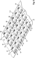
- the building sites can be arranged in a checkerboard-like pattern or in a hexagonal pattern.
- the electrical conductor tracks and pre-cuts are for everyone Construction site predefined and prestructured, depending on the configuration of the evaporator units to be manufactured.
- the flexible circuit board material is pre-assembled.
- the pre-assembly can also include the heating elements, in that instead of a pre-punching, a heating element is integrated into the circuit board material at each construction site as a passage opening for a separately placed heating element, which is electrically connected to the conductor tracks.
- steps a) and b) coincide, since the heating elements are also provided at the same time as the flexible circuit card material is provided.
- the connection between the heating element and the conductor track can already exist, for example in the case of a heating element integrated into the circuit card material as a foil heater.
- a heating element can be liquid-permeable or, for example, become liquid-permeable through microstructuring.
- the connection can also be formed first, for example in the case that the heating element is placed on the conductor tracks.
- Such a heating element can advantageously already have microchannels.
- the electrical conductor tracks can be applied to the circuit board material before the heating element is prepared and placed. This can take place, for example, with a process similar to color printing, e.g. polyjet, screen printing or stamp printing, or with targeted vapor deposition. However, any other suitable and known process is also conceivable.
- the circuit card material is pre-assembled or pre-structured through this step.
- pre-cuttings can also be introduced into the circuit board material before or after the heating element is prepared and placed. For example, pre-punchings can be made using suitable punching tools or other cutting and drilling tools. In other words, the circuit card material is pre-assembled or pre-structured through this step.
- the order of applying conductor tracks and introducing pre-punches can be carried out independently and therefore one after the other in any order or simultaneously.
- the placement of the or each heating element includes, for example using suitable SMT placement machines, the picking up and dispensing of each heating element, which can be, for example, a heater chip made essentially of silicon from a sawn wafer composite or a foil heating element, above which or any pre-punching formed in the circuit card material as a passage opening.
- the provision and placement of the heating element at the or each construction site also includes, for example, the provision and placement at every second construction site, if this is desired or necessary, or only at error-free construction sites. At every building site therefore means nothing other than at every desired, specified building site.
- step c) at least the or each heating element is partially enclosed, for example with suitable silicones, plastics, polyimide, rubber or other materials suitable as a sealing material, for example by means of the so-called film-assisted molding process.
- the sealing material has a multi-layer structure made of any combination of the aforementioned materials and is produced by multiple application of the film-assisted molding process, each with a different or the same one from the list of the aforementioned materials.
- Areas of the heating element, namely in particular the heating surface, are partially left out.
- sealing surfaces that are adapted to desired or required contours can be achieved by at least partially covering the construction site by at least partially encapsulating or reshaping it with sealing material.
- the sealing surfaces/seals integrated in the evaporator unit preferably with a defined sealing surface, can reduce the number of components required, such as additional sealants, when assembling an inhaler. This simplifies assembly and optimizes the automation of the process.
- a further advantage of at least partially covering each construction site with the sealing material is that, due to the shape of the casing, surrounding geometries of the evaporator unit, for example for air and/or liquid guidance, are included in the evaporator unit, namely are an integral part of each evaporator unit.
- each Evaporator unit can be limited by the circuit board material without any sealing material.
- step a) flexible circuit card material is provided, in which at least one construction site for an RFID chip is formed in the area of each construction site for an individual evaporator unit, the flexible circuit card material being pre-structured as an RFID antenna with regard to the position and / or course of predetermined conductor tracks or is pre-structured.
- the predetermined conductor tracks as an RFID antenna ultimately form at least one coil, whereby transmitting and receiving coils can be designed separately and separately from one another, preferably plane-parallel to one another with a small distance, or can be designed integratively as a common transmitting and receiving coil.
- transmitting and receiving coils can be designed separately and separately from one another, preferably plane-parallel to one another with a small distance, or can be designed integratively as a common transmitting and receiving coil.
- the preferred development also enables, in particular, a modular product concept in which either a heating element and/or an RFID chip can be integrated.
- the flexible printed circuit card material is or will be pre-structured at least with conductor tracks and/or pre-punched holes predetermined in terms of position and/or course for each construction site for the electronic connection of at least the RFID chip.
- the connections and/or the antenna itself are provided and incorporated during the structuring process of the circuit card material, which ensures particularly compact and efficient production of the evaporator units.
- an RFID chip is provided and placed at each construction site.
- the or each RFID chip is not an integral part of the flexible circuit card material, but is provided in step k) as a component to be fitted separately.
- NFC components can be provided and placed as an RFID chip.
- Other short-distance radio modules can also be used.
- the or each RFID chip can itself have an antenna in order to be able to communicate with the or each RFID antenna.
- the placement of the or each RFID chip is carried out, for example, using suitable SMT placement machines, as is the picking up and Hand over any RFID chip. For the electrical connection of the equipped RFID chips to conductor tracks, see below.
- the RFID chip can be an integral part of the circuit board material.
- the separate RFID chip is provided, placed and electrically connected to the conductor tracks, whereby the RFID chip is also optionally connected or connectable to the conductor tracks forming the RFI D antenna at each construction site.
- the connection can be made electrically or via radio signals.
- step c) in addition to partially covering each building site for the heating element, the building site for the RFID chip is also covered with the sealing material to form sealing surfaces.
- the flexible circuit card material is provided in step a) either by unrolling the circuit card material stored on rolls or by feeding sections of the circuit card material stored in magazines or the like.
- the rolls with flexible circuit board material can be stored in a space-saving manner and enable large numbers of building sites to be quickly prepared by simply unrolling/unwinding. The same applies to feeding sections of the circuit card material from magazines or the like.
- each construction site is at least partially enclosed with sealing material in such a way that additional sealing surfaces are provided both on the top side and on an underside of the flexible circuit board material opposite the top side on the outer surfaces of the casing for a connection to the evaporator unit that is free of additional sealants surrounding components of the inhaler are formed.
- additional, preferably defined, sealing surfaces in particular on the underside of the circuit card material, can also take place before/during/after applying the sealing material to the upper side. This means that the evaporator unit can be installed particularly easily and in a particularly sealing manner, for example in standardized evaporator assemblies or the like.
- step b) as Step b 1 ) the application of electrical contacting material at least on contact surfaces of the conductor tracks at each construction site on the top of the flexible circuit card material, as step b 2 ) the placement of the at least one heating element in the area of each construction site, such that the top with the underside of the Pre-cutting connecting circuit card material is completely or partially covered by the or each heating element, and as step b 3 ) includes the formation of an electrical connection between the heating element and conductor tracks at each construction site.
- step k) includes as step k 1 ) the application of electrical contacting material at least on contact surfaces of the conductor tracks at each construction site for the RFID chips on the top of the flexible circuit card material, as step k 2 ) the placement of the at least one RFID chip in the Area of each construction site, and as step k 3 ) the formation of an electrical connection between the RFID chip and conductor tracks at each construction site.
- electrical contacting material can also be applied to the contacts of the RFID chip.
- anisotropically conductive adhesive can be applied to the underside of the chip in the area of the contacts, with the chips prepared in this way being placed on the conductor tracks of the flexible circuit card material.
- the application of the electrical contacting material which can be, for example, solder paste, solder, sintering paste, electrically conductive adhesive or the like or a combination of one or more of the aforementioned contacting materials, can be carried out using suitable methods.
- suitable processes are screen printing, stencil printing, pad printing, dispensing or the like or a combination of one or more of the aforementioned processes. These procedures are carried out with the help of suitable devices.
- An example of a suitable device is an automatic screen printing machine.
- the heating element and also the RFID chip can preferably be placed using an SMT placement machine or the like.
- the electrical connection can be formed, for example, by converting the contacting material, for example by heat and/or pressure in an oven, a sintering press, contact thermodes or the like, or a combination of one or more of the aforementioned variants take place.
- wiring using so-called wire bonding is also possible in step b 3 ).
- NanoWiring process is used to electrically contact the heating element.
- nanowires are grown on a surface.
- the NanoWiring process is a galvanic process that is similar to pad printing. Here, a sponge carrying an electrolyte is pressed onto the substrate. A metallic turf with diameters of a few nanometers to a few micrometers and lengths of a few hundred nanometers to a few tens of micrometers grows into the porous layer of the sponge.
- a structuring process also called masking
- the substrates are only coated with NanoWiring coating in the intended areas.
- all materials that are not needed for the connection are removed and the substrate is cleaned.
- the galvanic process makes it possible to produce the nanowires from practically all galvanically depositable metals. For example, copper, gold or nickel can be used to produce the NanoWiring coating.
- the electrical connection takes place using the so-called Velcro sintering process.
- Only one substrate i.e. either the circuit card material or the heating element, has a NanoWiring coating.
- the second substrate i.e. either the heating element or the circuit card material, requires a copper-plated or gold-plated surface. Both substrates are pressed together (e.g. with 20 MPa) and a temperature in the range of 210 °C is brought into the connection zone, for example via a thermode. The same applies to the electrical contacting of the RFID chip.
- step d the sprue sections of the sealing material created when covering or enclosing the building sites with sealing material are removed in a step d).
- each construction site or the evaporator unit formed thereon - with the exception of at least one connecting web - is detached or separated from the circuit board material and all other connections that are not part of an evaporator unit.
- the release or separation of the sprue sections takes place at the same time as the evaporator units are separated from the belt made of the circuit board material.
- the circuit card material provided with the plurality of completed, sealing evaporator units can optionally be rolled up again onto a roll or collected in a magazine or the like for further use in step e).
- Rolling up/collecting can also take place after step b), in particular from the time of the permanent connection between the heating element and the circuit board material.
- Further use can be storage, temporary storage or further processing.
- the sealing evaporator units are separated from the flexible circuit board material for further use in step f).
- the separation can, for example, preferably be carried out by punching the circuit card material by separating the or each remaining connecting web from the circuit card material.
- the evaporator units can also be separated from the solid circuit board material, i.e. without completely or partially all-round pre-punching. Sawing or cutting are also options for separating.
- the individual evaporator units can then be further processed as tray or bulk goods or assembled directly
- At least one wick element can be placed in a step g) on or on the top of the flexible circuit card material on the free heating surfaces of the heating elements at each construction site.
- the wick element is preferably mounted on or on a top side (O) of the circuit card material.
- the wicking element can be placed on the free heating surface, particularly in the case of a one-piece design, for example using an SMT placement machine.
- the wicking element can also be designed as a granular wicking element and can be poured for assembly.
- a granular wick organ is at least partially formed from a large number of granular grains which, due to their filling and/or formation, form microchannels.
- the wicking element is also placed at the same time by placing the heating element.
- the wicking element can be placed together with step b) or after step b) in any sequence of steps.
- the or each wicking element can be placed before step c) or after step c).
- it can be placed/pressed/mounted/fixed, for example after step c), into a recess/pocket or the like formed by the sealing material.
- the wicking element can also be placed on the free heating surface after step c) and fixed by inserting it into a receptacle, for example formed in a component of an evaporator assembly.
- a receptacle for example formed in a component of an evaporator assembly.
- At least one additional electronic component can be placed in the area of each construction site in a step h), preferably together with steps b 2 ) and k 2 ).
- the electronic component is, for example, an ID chip, which serves as an identification element for clearly identifying the respective evaporator unit and can be designed as an NFC element, RFID element or as a digital memory module (e.g. EEPROM).
- the or each ID chip can optionally also be connected to an antenna, for example an NFC antenna or an RFID antenna. Different options are possible regarding the position of the or each ID chip on the construction site.
- the ID chip and any other component can also be at least partially covered or enclosed by the casing.
- the covering/enclosing can be done with the sealing material with which the heating element is also covered/enclosed, especially if the electronic component is placed before step c).
- the covering/enclosing can also be done in a separate step with the same sealing material or a second material, in particular a sealing material.
- step h contacting material is applied to contact surfaces of the conductor tracks at each construction site on the top and / or the bottom of the flexible circuit card material, and after step h ), preferably together, i.e. simultaneously with step b 3 ) or k 3 ), an electrical connection is formed between the or each electronic component and conductor tracks at each construction site.
- the production machines used for the heating elements can be used accordingly.
- each heating element and/or each RFID chip and/or each additional electronic component is electrically connected to the conductor tracks of the flexible circuit card material by using one or more methods from the list: direct contacting by means of silver sintering, eutectic bonding, conductive bonding, anisotropic conductive bonding, Velcro welding, Velcro sintering, soldering, welding.
- direct contacting by means of silver sintering, eutectic bonding, conductive bonding, anisotropic conductive bonding, Velcro welding, Velcro sintering, soldering, welding.
- step c) when covering or enclosing each construction site, at least sections of an air flow channel are formed from and/or with the sealing material on the underside of the circuit board material at each construction site.
- the sections of the air flow channel can also be formed before step c) and after step c), namely by the sealing material with which the heating element is also covered/enclosed, or with a second sealing material.
- This embodiment leads to a so-called “open” variant, since the air flow channel only becomes a continuous, circumferentially closed air flow channel in combination with components surrounding the evaporator unit.
- a tubular, pre-assembled section can be placed on the underside of the circuit board material as part of an air flow channel at each construction site and enclosed and thus fixed using additional sealing material.
- This embodiment leads to a so-called “closed” variant, since the evaporator unit itself comprises a continuous section of the air flow channel that is closed on the circumference.
- steps a) to c) are carried out one after the other at a separate or the same production station of a production line, such that a large number of construction sites are processed at the same time in each step. This ensures a high level of automation for fast and efficient large-scale production with highly optimized parts logistics.
- the entire manufacturing process of the evaporator units takes place in a common production line with several production stations, which further supports the above advantages.
- the flexible, pre-structured circuit card material preferably made of polyimide
- the flexible, pre-structured circuit card material is unwound as an endless strand from a supply roll and transported continuously or intermittently through the production line comprising several production stations.
- This makes it possible, for example, to unroll the endless strand, so that, for example, step b) is carried out at a first production station at a large number of construction sites for a large number of evaporator units.
- step b) After completing step b) you can Endless strand are transported further in order to transport a subsequent section of the endless strand to carry out step b) into the area of the first production station.
- the leading section which has already been subjected to method step b), can then be located in a second production station for carrying out step c).
- This process sequence can be carried out continuously up to step h) and including step k). All manufacturing steps can therefore preferably be carried out completely automatically using a production line.
- the method can also be carried out accordingly by feeding sections of the flexible circuit card material with one or more building sites, for example in magazines, cassettes or the like, and transporting them through the production line with or without a magazine or the like.
- an evaporator unit mentioned at the beginning which is characterized by a casing made of sealing material, which at least partially covers the circuit board section and the heating element while keeping a heating surface free and is provided with sealing surfaces on the outside.
- the flexible circuit board material of the circuit board section offers, in addition to the possibility of mass production, a particularly energy-efficient design of the cross section of the conductor tracks. Due to the casing of the heating element made of sealing material, this is on the one hand securely held mechanically and on the other hand the preferably defined sealing surfaces facing outwards, i.e.
- the evaporator unit as a whole has a dual function, namely as an evaporator on the one hand and as a sealant on the other , so that with the evaporator unit according to the invention with integrated sealant, assembly with reduced parts is guaranteed.
- the design according to the invention creates an energy-efficient, reliable evaporator unit that is suitable for mass production.
- the circuit card section comprises at least one RFID chip and at least one RFID antenna.
- the or each RFID chip and the or each RFID antenna are therefore an integral part of the carrier substrate and thus of the evaporator unit itself, so that a contactless transmission of data, for example between the evaporator unit or an evaporator cartridge comprising the evaporator unit and a, is possible in a compact and efficient manner Cartridge carrier or between the evaporator unit or an inhaler comprising the evaporator unit and a reading device, such as a smartphone, is ensured.
- Typical Data that can be transferred includes, for example, data on correct vaporization, the authorization of the user of the inhaler, the activation of the vaporizer cartridge or tracking the usage behavior by the user himself and/or a doctor or pharmacist, especially for medically used inhalers.
- the circuit board section is formed from polyimide
- a doped silicon chip with microchannels is electrically connected to the conductor tracks as a heating element by direct contacting using silver sintering
- the circuit board section and the silicon chip are partially enclosed by silicone or polyimide, so that on the one hand the silicon chip is held mechanically and on the other hand Sealing surfaces that are preferably defined on the outside are formed.
- the sealing surfaces can be undefined. However, the sealing surfaces preferably have predetermined and reproducible, i.e. defined, sealing surfaces.
- An alternative to silicone can be a suitable plastic or polyimide.
- the circuit card section and silicon chip are enclosed by the sealing material in such a way that liquid can be transported through the microchannels of the silicon chip from a first side of the silicon chip to a second side of the silicon chip.
- a so-called foil heater can also be used or provided as a heating element, which has a microstructure by means of which liquid can be transported from a first side of the foil heater to a second side of the foil heater.
- the conductor tracks embedded in the flexible circuit card material protrude from the casing formed by the sealing material to form a flexible contact, in particular reversibly and/or flexibly bendable.
- the conductor tracks embedded in the circuit card material are electrically conductive and contact the silicon chip or the foil heater or any other heating element. This makes it possible to dispense with further contacts, particularly in components surrounding the evaporator unit, for example an evaporator assembly or evaporator cartridge, which further reduces the variety of parts and, in particular, enables greatly simplified and space-saving assembly.
- An expedient embodiment is characterized in that the heating surface of the heating element is at least partially covered on the top by a wick element. This completes the evaporator unit for particularly efficient and reliable use.
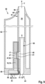
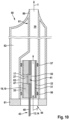
- An optional embodiment is characterized in that at least one pipe section is designed and/or arranged as a section of an air flow channel on the underside of the circuit board section, the pipe section having an opening directed towards the heating element.
- the pipe section can be formed from sealing material and/or a separate pipe.
- the evaporator unit is particularly preferably produced using a method according to one or more of claims 1 to 23.
- an evaporator assembly mentioned at the beginning, which has an evaporator unit according to the second aspect of the invention and an adapter plug into which the evaporator unit is inserted, the evaporator unit or its casing being at least partially covered with a Outer surface of the casing rests sealingly against an inner geometry of the adapter plug.
- the internal geometry of the adapter plug here refers to surfaces of an area in the adapter plug that is set up to accommodate the evaporator assembly. Due to this design of the casing in conjunction with the internal geometry of the adapter plug, there is a fluid connection exclusively via the evaporator unit in the direction of the flow channel without additional sealing means.
- the evaporator assembly is designed to be sealed, with the exception of the evaporator unit in the area of the heating surface for receiving liquid from a storage tank and generating steam in the direction of an air flow channel.
- the evaporator assembly comprises at least a portion of an air flow channel which is formed by the evaporator unit and/or the adapter plug.
- the adapter plug can have its own section of an airflow channel have, wherein the air flow channel has an opening for a connection to the evaporator unit.
- the air flow channel can also be formed entirely by the evaporator unit or partially by the evaporator unit in combination, for example, with a wall of the adapter plug or a section of the internal geometry of the adapter plug described above.
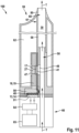
- an evaporator cartridge mentioned at the beginning which has a hollow body with at least a section of an air flow channel, a storage tank for storing liquid, and an evaporator assembly according to the third aspect of the invention, wherein the evaporator assembly with is sealingly connected to the hollow body and the storage tank in such a way that the section of the air flow channel of the evaporator assembly and the section of the air flow channel of the hollow body form a common air flow channel and the storage tank has at least one access opening to the flow channel in which the evaporator unit is placed.
- the object is achieved in particular by an inhaler mentioned at the outset, which has a cartridge carrier comprising at least one electronic control unit and an electrical energy source and a vaporizer cartridge according to the fourth aspect of the invention.
- the aforementioned devices, especially the inhaler can be set up or used, particularly with regard to medical applications, in such a way that one or more of the following additional advantages occur: While in known inhalers for powdered medications the inhaler generally needs to be cleaned before and/or after use or even further maintained, this is generally not necessary with an inhaler according to the invention, especially since the medication is in liquid form in the vaporizer cartridge or whose storage tank is enclosed.
- an inhaler according to the invention can be used for various therapies, for which purpose either the vaporizer cartridge with a liquid with at least one corresponding therapy-related active ingredient is introduced accordingly with regard to the therapy to be used, or an already assembled vaporizer cartridge is replaced with another vaporizer cartridge suitable for the therapy to be carried out with the corresponding content is exchanged.
- the inhaler according to the invention does not require dispersants and propellants (in particular propellants), which can often be unfavorable or even dangerous to health, particularly in a medical environment.
- a propellant gas is here understood to mean, in particular, a gas which has a pressure that is higher than the ambient pressure and which, in typical conventional inhalers, serves to atomize and accelerate the medication to be administered.
- a compression device for generating an air or other gas stream, as well as associated ones, can also be used There is no dead volume in the inhaler housing. In this way, a reduction in the required installation space can be achieved, since only one air duct is required instead of space-consuming pressure chambers or complex spring systems for pre-tensioning the inhaler.
- the lower installation space requirements can in turn be advantageous, particularly with regard to the increase in design freedom in the design of the inhaler that is made possible (for example, smaller, more attractive designs are possible).
- an inhaler With an inhaler according to the invention, on the other hand, the user can transfer the medication into the lungs through his own breathing air after the medication has been vaporized. Because it is possible to avoid the use of propellants to atomize the medication, problems that often occur with patients when using conventional inhalers with propellants, such as irritation of the throat or coughing, can be effectively avoided. There is also no need for manual tensioning of the inhaler to atomize the medication, which is often necessary with conventional inhalers. In this way, user-friendliness can be improved, particularly by avoiding manual preparation procedures before using the inhaler.
- the seal provided according to the invention also has the advantage that an undesirable or, depending on the active ingredient, possibly even potentially harmful entry of unevaporated liquid into the air duct with the associated possibility of the user absorbing the liquid as such is effectively counteracted and thus the safety of the inhaler is ensured .
- the inhaler according to the invention in particular its heating element, is operated electrically, a high metering accuracy of the heating element can be achieved due to the precise controllability of the heating operation.
- This promotes the quality of use in particular, in that the evaporated amount of medication can be very well adapted to the individual needs of the user or patient and, in particular, can be limited in terms of a maximum dose, which in turn can be used to increase the safety of use when using the inhaler .
- An inhaler according to the invention can preferably have an output quantity control device.
- This can in particular be a counting device, in particular a counting device for counting doses of the liquid that have evaporated in a defined observation period (for example in the period since the counting device was last initialized or reset).
- the doses to be counted here can in particular be (i) a number of evaporated fillings of the evaporator cartridge or its storage tank or of different evaporator cartridges or their respective storage tanks, or (ii) a number of bursts of steam emitted by the inhaler in the period under consideration or predetermined steam units come into question.
- the output quantity of the evaporated substance can be recorded with a view to maintaining a desired dosage and thus simple and reliable monitoring of the dosage can be achieved.
- this control option with regard to the use of individual doses it is not necessary to load the inhaler individually for each individual dose to be administered or vaporized.
- the evaporator unit or the evaporator assembly and evaporator cartridge shown in the drawing when assembled into an inhaler, are used to inhale vapor enriched with active ingredients, e.g. nicotine, and/or aerosols made of liquid, and are therefore described in connection with an e-cigarette.
- active ingredients e.g. nicotine, and/or aerosols made of liquid
- Other uses in particular use in the medical field, are expressly included, especially since the evaporator units and the evaporator assembly in particular allow universal use, since the standardized evaporator unit or evaporator assembly enables integration/installation into different evaporator cartridges and/or different tank shapes.
- the method is used to produce vaporizer units 10 as part of inhalers 100.
- the method can be carried out manually or semi-automatically, for example by only carrying out individual process steps automatically.
- the method is preferably designed for fully automated execution or production of evaporator units.
- the method is characterized in that at least the following steps are carried out in the predetermined order a) to c), namely a) providing a flexible circuit card material 11 with a plurality of building sites 12 for individual evaporator units 10, the flexible circuit card material 11 at least with with respect to position and/or course predetermined conductor tracks 13, 14 and/or pre-cuttings 15, 16, 24 for each building site 12 is optionally pre-structured or will be pre-structured, b) providing and placing at least one heating element which is electrically connected or can be connected to the conductor tracks 13, 14 17 at the or each construction site 12, and c) at least partially covering each construction site 12 with a sealing material 18 to form a partial casing 19 for each evaporator unit 10 formed, the sealing material 18 being applied in such a way that the casing 19 formed from sealing material 18 each Heating element 17 while keeping a heating surface 20 free at least on a top side O of the flexible circuit card material 11 at least in the edge area, and at least the outer surfaces of the casing 19 facing
- the circuit card material 11 can be provided in different ways (see below).
- the circuit card material 11 can be provided in a pre-structured manner or can be pre-structured after provision and before further processing, i.e. in the manufacturing process of the evaporator units 10.
- the heating element 17 can already be connected, for example in the case that the heating element 17 is a foil heater, while the heating element 17, for example in the case that the heating element 17 is a silicon chip, can still be connected in the manufacturing process .
- the or each heating element 17 can be arranged on both sides of the circuit card material 11, for example only on the top or only on the bottom, with the top and bottom ultimately being interchangeable, since the assignment depends on how the circuit card material 11 is ultimately held/transported or the evaporator unit 10 formed thereon is ultimately mounted, or on both sides with a plated-through hole.
- In the edge area means that the heating element 17 is sealed all around, such that a fluid connection between the top O and the bottom U of the circuit card material 11 adjacent to the heating surface 20 is excluded.
- the flexible printed circuit card material 11 as a substrate can, for example, be a single-lane belt 11.1 (also referred to below as an endless belt) (see in particular Figure 3 ) or a multi-lane endless belt (see e.g Figures 5 to 7 ), which is stored on rolls or other storage containers and is unrolled or unwound continuously or intermittently in the transport direction T for further processing.
- the flexible printed circuit card material 11 as a substrate can, for example, also be divided or separated into sections comprising a building site 12 or several building sites 12, which are stored and supplied in magazines, cassettes or the like.
- the circuit board material 11 can have further pre-cuttings 16, i.e. recesses or openings, at each construction site 12 of an evaporator unit 10, in particular in cases in which heating elements 17, which are to be equipped separately, are used for the evaporator units 10.
- the pre-cuttings 16 at each construction site 12 serve as a through opening 41 to enable a connection between the storage tank and the air flow channel via the evaporator unit 10, which will be discussed further below.
- the heating element 17 is an integral part of the circuit card material 11, for example as a foil heater
- an area 92 of microstructuring can optionally be provided, which is designed to be liquid-permeable.
- Further pre-cuttings 24 serve to allow the sealing material 18 to flow from the top to the bottom or vice versa.
- the pre-cuts 24 can also serve to pre-release the evaporator unit 10 from the circuit card material 11 in sections.
- Each building site 12 also includes at least two conductor tracks 13, 14 for electrically contacting the heating element 17.
- Both the conductor tracks 13, 14 and the pre-cuts 15, 16, which are assigned to the circuit card material 11 on the or each side edge 22, 23 and each building site 12 are pre-structured or will be pre-structured in such a way that they are adapted to a predefined structure/layout of conductor tracks 13, 14 and pre-cuttings 15, 16, 24 to match the evaporator units 10 to be produced.
- the number of building sites 12 on an endless belt 11.1 can be arbitrary and vary in terms of arrangement/pattern, just as the layouts of the building sites 12 can vary. However, all building sites 12 on an endless belt 11.1 are preferably designed identically.
- step a) executing step a) inevitably and simultaneously leads to executing step b), so that in combination with step c), at least a two-step process results.
- Steps a) and b) can be carried out one after the other in the event that the heating element 17 is not formed integrally with the circuit card material 11 (see further below), so that in combination with step c) at least a three-step process results.
- each building site 12 is equipped with at least one heating element 17, for example by means of an SMT placement machine from the top side O of the circuit card material 11 (see illustration according to Figure 3.3 ), which is also known as the contact page.
- At least partially covering each Building site 12 with the sealing material 18 takes place at least from the top side O of the circuit card material 11.
- each heating element 17 is covered all around at least in the edge area, with the sealing material 18 preferably extends as close as possible to the active, actual heating surface 20 (see illustration according to Figure 3.5 ), which remains free of sealing material 18 to ensure liquid/steam transport through the heating element.
- the sealing material 18 preferably extends as close as possible to the active, actual heating surface 20 (see illustration according to Figure 3.5 ), which remains free of sealing material 18 to ensure liquid/steam transport through the heating element.
- a top side O of a belt 11.1 made of flexible circuit card material 11 with several building sites 12 is shown after step c).
- film foils At least one, preferably two, are first placed in defined shapes, where they fit tightly against the inside of the shapes, for example by means of vacuum, before the endless belt 11.1 is introduced and preferably Silicones are supplied as sealing material 18 to form the casing 19.
- a suitable plastic or polyimide is used.
- the casing 19 With the casing 19, at least the heating element 17 is partially covered and parts of the circuit card material 18 are covered or sealed in each construction site 12.
- each construction site 12 can also be covered with the sealing material 18, for example in the event that the heating element 17 is placed on the underside, from the underside U of the circuit card material 11 or from both sides.
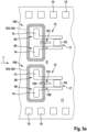
- flexible circuit card material 11 is provided in step a), see e.g Figure 5a , in which at least one building site 101 for an RFID chip 102 is formed in the area of each building site 12 for an individual evaporator unit 10, and that the flexible circuit card material 11 is pre-structured as an RFID antenna 105 with regard to the position and / or course of predetermined conductor tracks 103, 104 or is pre-structured.
- the construction site 101 forms a connection location for another electronic component, for example the (RF) ID chip 102.
- the RFID antennas 105 are on the bottom/back of the Circuit card material 11 are arranged or formed, with corresponding plated-through holes 150 on the top.
- the printed circuit card material 11 can be pre-structured differently with regard to the additional building site 101 for the RFID chip 102 and its electrical connection or radio connection.
- the conductor tracks 13, 14 for the heating element 17 can form the RFID antennas 105 as a coil.
- the separate conductor tracks 103, 104 form the coil as an RFID antenna 105.
- Several conductor tracks can also be pre-structured in order to form a receiving antenna (receiving coil) on the one hand and a transmitting antenna (transmitting coil) on the other hand.
- the communication between the RFID antenna(s) and the RFID chip can take place electrically or via electromagnetic coupling, as can the power supply to the RFID chip.
- the pre-structured RFID antennas can preferably be arranged and designed plane-parallel to one another and at a short distance.
- the flexible circuit card material 11 is or will be pre-structured at least with predetermined conductor tracks and/or pre-cuts for each construction site 101 for the electronic connection of at least the RFID chip 102.
- the RFID chip 102 can be an integral part of the pre-structured circuit card material 11.
- the RFID chip 102 is a separate component, in a step k), which can correspond to step h) described below and which can take place before, with or after step b), at each construction site 101 an RFID chip 102 provided and placed.
- the RFID chip 102 which is electrically connected or connectable to the conductor tracks, is or is provided and placed, the RFID chip 102 being selectively connected or connectable to the conductor tracks 103, 104 forming the RFID antenna 105 at each construction site 101, and electrically or via electromagnetic coupling.
- step c) in addition to partially covering each construction site 12 for the heating element 17, the construction site 101 for the RFID chip 102 is also covered with the sealing material 18 to form sealing surfaces. In other words, the RFID chip 102 is protected from the environment by the sealing material 18.
- the flexible circuit card material 11 can be provided in step a) either by unrolling the circuit card material 11 stored or stored on rolls or by feeding sections of the circuit card material 11 stored in magazines or the like.
- each building site 12, 101 is at least partially enclosed with sealing material 18, such that additional sealing surfaces 21 are provided on the outer surfaces of the casing 19 both on the upper side O and on an underside U of the flexible circuit card material 11 opposite the upper side O a connection to the components of the inhaler 100 surrounding the evaporator unit 10 (more on this below) can be formed that is free of additional sealants.
- each building site 12, 101 is enclosed from both sides of the endless belt 11.1, for example by overmolding from the top side O and the underside U or by overmolding exclusively from the top side O, the sealing material 18 being pre-punched 24 at each building site 12, 101 reaches the bottom U.
- the sealing surfaces 21 are preferably partially or completely defined and designed to be reproducible.
- an underside U of an endless belt 11.1 made of flexible circuit card material 11 with several building sites 12 is shown after step c).
- the pre-cuts 24 also serve to be able to separate each evaporator unit 10 from the circuit board material 11 as easily as possible.
- the pre-cuttings 24 are preferably formed all around each building site 12, 101.
- only one web 70 or more than two webs 70 can be provided.
- pre-cuttings 24 for later cutting out can also be completely or partially dispensed with. In this case, only pre-cuttings 24 are provided if sealing material 18 is to flow around the substrate.
- step b) includes as step b 1 ) the application of electrical contacting material 25 at least on contact surfaces 26 of the conductor tracks 13, 14 (see illustration according to Figure 3.2 ) at each construction site 12 on the top side O of the flexible circuit card material 11, as step b 2 ) placing the at least one heating element 17 in the area of each construction site 12, such that a pre-punching 16 connecting the top side O with the underside U of the circuit card material 11, which later forms the through opening of the evaporator unit 10, is completely covered by the or each heating element 17 (see illustration according to Figure 3.3 ), and as step b 3 ) the formation of an electrical connection between heating element 17 and conductor tracks 13, 14 at each construction site 12.
- sintering paste for example, is applied to the contact surfaces 26 at a second manufacturing station.
- Each heating element 17 is then picked up by an automatic placement machine, positioned and deposited/placed on the contact surfaces 26 wetted with sintering paste, so that the pre-punching 16 forming the passage opening is completely covered by the heating element 17.
- a sintering process for example in a sintering press, a permanent electrical connection is created between the heating element 17 and the conductor tracks 13, 14, whereby the heating element 17 is additionally fixed on the circuit card material 11.
- each heating element 17 is electrically connected to the conductor tracks 13, 14 of the flexible circuit card material 11 by direct contact using silver sintering.
- the steps b 1 ) and b 2 ) can also be linked to one another, for example by equipping the heating element 17 with a film or the like provided with contacting material 25, so that the heating elements 17 essentially press the contacting material 25 through and place them on the contact surfaces 26 "bring along".
- any other method described above for establishing an electrical connection between the conductor tracks 13, 14 and the heating element 17 is suitable.
- the heating element 17 can also be pre-assembled with contacting material 25, for example by having a silicon chip on a wafer already laminated with contacting material 25.
- step k) includes as step k 1 ) the application of electrical contacting material 25 at least on contact surfaces of the conductor tracks at each construction site 101 on the top side O of the flexible circuit card material 11, as Step k 2 ) placing the at least one RFID chip 102 in the area of each building site 101, and as step k 3 ) forming an electrical connection between RFID chip 102 and conductor tracks at each building site 101.
- this can electrical contacting material in step k 1 ) can optionally also be applied directly to the contacts of the RFID chip, with the RFID chip prepared in this way then being placed on the construction site 101.
- the heating element 17 is placed and connected on the top of the circuit card material 11.
- the heating element 17 is placed on the top, with the electrical contacts, for example the conductor tracks 13, 14, being arranged on the bottom.
- Pre-cuttings 24 in the area of the electrical contacts of the heating element 17 connect the top and the bottom, so that contacting material 25 is applied in the area of the pre-cuttings 24, which after step b 3 ) creates a connection between the heating element 17 on the top and conductor tracks 13, 14 the underside.
- contacting material 25 is applied in the area of the pre-cuttings 24, which after step b 3 ) creates a connection between the heating element 17 on the top and conductor tracks 13, 14 the underside.
- steps d) to h) and k) mentioned below does not represent a mandatory order of the steps. Rather, steps d) to h) and k) can be carried out in virtually any order. Particularly preferably, step k) is carried out directly before or after step b).
- the endless belt 11.1 can, for example, be rolled up again in order to be able to use a roll-to-roll process for the production of evaporator units 10.
- step a) a roll with rolled-up flexible circuit card material 11 is provided.
- steps b) and c) a large number of evaporator units 10 are imaged on it.
- the flexible circuit card material 11 can be rolled up again/again in a step e) for further use, for example for transport, storage or the like. If sections of circuit card material 11 are processed, they can be fed back into a magazine or the like for further use, for example in step e).
- sprue points arise due to the process, i.e. material webs, which result from casting, spraying or other processing of the sealing material 18.
- the sprue sections of the sealing material 18 that arise when covering or enclosing the construction sites with sealing material 18 are removed in a step d).
- the removal can also take place later, for example when individual evaporator units 10 are separated out.
- the renewed rolling up can take place, for example, after step c) and optionally after each further step. Rolling up can optionally even take place after step b).
- the printed circuit card material 11 provided with the large number of completed, sealing evaporator units 10 can be rolled up onto a roll free of sprue sections for further use, preferably for the first time or again in step e). The same applies when using sections of the circuit card material 11 in magazines or the like.
- the manufactured, sealing, i.e. provided with sealing surfaces 21, evaporator units 10, which are sealed in combination/by assembly with other components of the inhaler 100 without additional sealants, are separated from the flexible circuit board material 11 for further use in a step f).
- the rolled-up circuit card material 11 provided with evaporator units 10 can be unrolled again at a later point in time, for example at an assembly site for evaporator units 10.
- the isolation can be done, for example, by punching, cutting or the like. Separating can also take place immediately after step d), for example to produce tray or bulk goods.
- a step g) at least one wick element 27 is placed on the top side O of the flexible circuit card material 11 on at least part of the free heating surfaces 20 of the heating elements 17 at each construction site 12.
- the wick element 27 can, for example, be designed as a block of ceramic or as a glass fiber or cotton pad or otherwise in one piece and can be placed, for example, together with step b) or after step b) in any sequence of steps.
- the joint assembly in step b) is particularly preferred when the wick element 27 and the heating element 17 form a composite.
- the wick element 27 can also be placed after step c) or after step d) or even after step f).
- the wicking element 27 is, for example, a granular wicking element 27, the granules can, for example after being separated, be poured into a recess 28 formed in the casing 19, in which the heating surface 20 of the heating element 17 is exposed.
- the wick element 27 can then be fixed, for example by gluing or other connection techniques.
- the wick element 27 can also be placed and/or fixed on a side opposite the heating element 17. Neither the heating element 17 nor the wick element 27 necessarily have to be arranged on one side and in particular not necessarily on the top.
- step h) which can correspond to step k
- at least one additional electronic component can be placed in the area of each construction site 12, preferably together with step b 2 ) or k 2 ).
- step h) can also take place before or after step b 2 ) or k 2 ).
- contacting material 25 is applied to contact surfaces 26 of the conductor tracks 13, 14 at each construction site 12 on the top side O and/or the bottom side U of the flexible circuit card material 11, and after In step h), preferably together with step b 3 ) or k 3 ), an electrical connection is formed between the or each additional electronic component and conductor tracks 13, 14 at each construction site 12.
- the electronic components can be the conductor tracks 13, 14 of the heating element 17.
- the electronic components can also be electrically contacted on their own conductor tracks.
- the electronic components can be placed on the side of the heating element 17 and/or on the opposite side.
- the or each additional electronic component for example ID chips, sensors or other electronic components, can be partially or completely covered or enclosed by the sealing material 18. This can be done, for example, in step c). There is also the possibility that the electronic components are completely or partially encased in a separate step by the same sealing material 18 or another material.
- Each heating element 17 and/or each RFID chip 102 and/or each electronic component, in particular each ID chip, is electrically connected to the conductor tracks 13, 14, or other contacting surfaces of the circuit card material 11 by using one or more methods from the (not final) list: direct contacting using silver sintering, eutectic bonding, conductive bonding, anisotropic conductive bonding, KlettWelding, KlettSintering, soldering, welding.
- the RFID chips and other electronic components can optionally also be connected to the conductor tracks 13, 14 of the circuit card material 11 using wire bonding.
- the electronic components RFID chip, etc.
- step c) when covering or enclosing each building site 12 at least, preferably web-like, sections 29 of an air flow channel 30 can be formed from and/or with the sealing material 18 on the underside U of the circuit board material 11 at each building site 12 (please refer e.g Figure 7 ).
- the sections 29 form part of the wall of the air flow channel 30 to be formed.
- the molding of parts of the air flow channel 30 or a fully formed air flow channel 30 can also be done in a separate step with a material that differs from the sealing material 18.
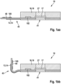
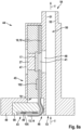
- a tubular, pre-assembled section 31 (also called pipe section 31) can be placed at each construction site 12 as part of an air flow channel 30 on the underside U of the circuit card material 11 and enclosed and thus fixed by means of additional sealing material 32 (see Figures 2 and 10 ).
- additional sealing material 32 see Figures 2 and 10 .
- sealing and/or air flow channel sections can be formed on the underside U of the flexible circuit card material 11 before/during/after step c). The sealing and/or flow function of the evaporator unit 10 is described in more detail below in connection with assembly.
- At least steps a) to c) are carried out one after the other at a separate or the same production station of a production line 33, such that in each step at each production station 34 to 39 a large number of construction sites 12, 101 are or can be processed at the same time.
- a production station 34 to 39 there is the option that the sintering to establish the electrical connection and the enclosing with sealing material 18 takes place in/at a production station.
- simultaneous means that the same steps are carried out at several building sites 12, 101 or that several/different steps are carried out at several building sites 12, 101.
- the entire manufacturing process of the evaporator units 10 is particularly preferably carried out in a common production line 33 with several production stations 34 to 39.
- An exemplary production line 33 is shown schematically Figure 3 indicated.
- a production station 34 in a step a) the or each roll with rolled-up circuit card materials 11 is stored and made available for unwinding or, if necessary, for active unrolling.
- electrical contacting material 25 is applied in a step b 1 ) or k 1 ) (illustration according to Figure 3.2 ).
- a production station 36 for example an SMT assembly machine, in a step b 2 ) or k 2 ), the or each heating element 17 or the or each RFID chip 102 is picked up and placed (illustration according to Figure 3.3 ).
- each building site 12, 101 is at least partially covered or enclosed with sealing material 18 (illustration according to Figure 3.5 ).
- the evaporator units 10 are separated in a step f) by being separated/detached from the circuit card material 11 (illustration according to Figure 3.6 ).
- the flexible, pre-structured circuit card material 11 which is preferably made of polyimide, is unwound in one example as an endless strand from a supply roll and transported continuously or intermittently through the production line 33, which includes several production stations 34 to 39. In other examples, sections of circuit board material 11 may be transported through the production line in magazines, for example. Alternatively, all of the contacting methods described above can also be used during the manufacturing process. Two or more than two production lines 33 can also be provided.
- the circuit card material 11 is provided on rolls.
- the circuit card material 11 is processed on a first production line 33.
- the circuit board material 11 is printed with a sintering paste at the positions where the heating elements 17 will later be placed.
- the heating elements 17 are placed using an SMT placer, i.e. a pick-and-place device.
- the circuit card material 11 is then dried from below with a hot plate. Sintering is done with hot stamps from above on the same plate. Finally, the populated circuit card material 11 is rolled up again.
- the above sequence of steps can be repeated on another production line 33 with a corresponding structure or the same production line 33, possibly with adapted programs for printing and placing at least one (RF) ID chip, so that heating elements 17 and (RF) ID chips 102 populated circuit card material 11 is provided rolled up.
- RF radio frequency
- the printed circuit card material 11 prepared and populated in this way can then be further processed on a further production line, which is preferably separate due to lower capacities, with the or each additional production line being designed as a FAM line (film-assisted molding).
- the prefabricated circuit card material 11 can be unrolled in the FAM line or FAM device. After unrolling
- the connection sites/construction sites including the heating elements 17 and the (RF) ID chips 102 are coated with silicone. After the sprue residue has been separated, the circuit card material 11 is rolled up again.
- the process is used to produce individual evaporator units 10 (see e.g Figure 4 ).
- the evaporator units 10 according to the invention as part of inhalers 100 are characterized in that they have the following components: a circuit card section 40 made of flexible circuit card material 11, the circuit card section 40 comprising at least two conductor tracks 13, 14 and a passage opening 41, which has an upper side O of the circuit card section 40 connects to an underside U of the circuit board section 40, heating element 17, which completely covers the passage opening 41 from the top side O and is in electrical contact with the conductor tracks 13, 14, and a casing 19 made of sealing material 18, which covers the circuit board section 40 and the heating element 17 at least partially covers while keeping a heating surface 20 free and is provided with sealing surfaces 21 on the outside.
- the circuit board section 40 can comprise an integral heating element 17, which has an area 92 of microstructuring and is electrically connected to the conductor tracks 13, 14 (see Figure 5 ).
- FIGs 1a), 1b ) and 2 enlarged representations of preferred embodiments of evaporator units 10 are shown in section, in which a wick element 27 is placed on the heating surface 20.
- a basic variant without air flow channel 30 is shown. The passage of steam generated in the direction of the flow channel 30 is ensured via the passage opening 41 and the liquid-permeable heating element 17.
- a prefabricated pipe section 31 is formed on the underside U of the circuit board section 40 to form the air flow channel 30 with the evaporator unit 10, the pipe section 31 being connected to the evaporator unit 10 by means of the additional sealing material 32.
- the evaporator unit 10 can be, for example, the in Figure 7 have web-like sections 29 shown.
- These web-like sections 29 form a partial wall of an air flow channel 30 that is not completely closed in the circumferential direction, which interacts with walls or surfaces or the like of other components (such as the internal geometry of the adapter plug, an evaporator cartridge or the like) and thus an air flow channel 30 that is completely closed in the circumferential direction forms.
- the electrical contacting i.e. electrical connection of the heating element 17 to the conductor tracks 13, 14, can take place directly or indirectly.
- direct contacting at least part of the conductor tracks 13, 14, which is to be or is contacted electrically with the heating element 17, is arranged on the same side of the circuit board section 40 as the heating element 17.
- the electrical contact is made using the methods described here in connection with the invention.
- indirect contacting the part of the conductor tracks 13, 14 that is to be or is contacted electrically with the heating element 17 is arranged on the side of the circuit card section 40 which is to be arranged opposite the side on which the heating element 17 is arranged .
- electrical contact is made, i.e. the electrical contacts of the heating element 17 are connected to the conductor tracks 13, 14 through the circuit board section 40. Accordingly, these contacts are not shown or not visible in the exemplary embodiments shown.
- one or more openings can be provided in the circuit board section 40, in which or in which electrically conductive material is arranged, which establishes the electrical connection between the heating element 17 and the conductor tracks 13, 14.
- electrically conductive material is arranged, which establishes the electrical connection between the heating element 17 and the conductor tracks 13, 14.
- continuous electrical connections can already be made during the pre-assembly of the circuit card material 11 from one side to the other, ie from the top O to the bottom U of the circuit card material 11 be or will be provided, so that on the side opposite the conductor tracks 13, 14 there are contact points with which the heating element 17 can be electrically connected.
- the electrical contact is made using the methods described here in connection with the invention.
- the circuit card section 40 comprises at least one RFID chip 102 and at least one RFID antenna 105.
- the RFID antenna 105 can be formed by windings of the heating element 17.
- the or each RFID antenna 105 is preferably formed by its own conductor tracks 103, 104.
- the RFID antenna 105 and the heating element 17 can be arranged or formed on the same side of the circuit board section 40 or on opposite sides.
- the RFID antenna 105 can preferably be arranged on the circuit board section 40 in such a way that it encloses the heating element 17 in the plane of the circuit board section 40 in an interior area enclosed by it.
- the location and/or position of the RFID chip 102, the number of RFID chips 102, as well as the location and/or position and/or orientation of the or each RFID antenna 105 in relation to the heating element 17 can vary. Data transmission can optionally be carried out wirelessly.
- the RFID chip 102 can contain an antenna.
- the circuit board section 40 of the evaporator unit 10 is preferably formed from polyimide, although other flexible substrate materials can also be used.
- a doped silicon chip as a heating element 17 is electrically connected to the conductor tracks 13, 14 by direct contacting using silver sintering.
- Other components in particular MEMS components (micro-electro-mechanical components) that are essentially made of silicon or have silicon or p- or n-doped silicon and are designed to be liquid-permeable, can also be used as the heating element 17.
- so-called film evaporators/film heaters can also be used as heating element 17.
- the circuit card section 40 and the silicon chip are at least partially enclosed by silicone or polyimide, so that on the one hand the silicon chip is held mechanically and on the other hand, preferably defined sealing surfaces 21 are formed on the outside.
- silicones instead of silicones, other materials that can be processed in particular using the film-assisted molding process and have a sealing effect when processed can also be used. Examples of other materials that can be processed using the film-assisted molding process are polyimide or plastics.
- a section of the conductor tracks 13, 14 embedded in the flexible circuit card material 11 protrudes bendably from the casing 19 formed by the sealing material 18 to form a flexible contact 43.
- the Figure 1a represents the embodiment in which the flexible contact 43 has not yet been bent.
- the Figure 1b represents the flexible contact 43 in the bent state.
- the heating surface 20 on the top side O is at least partially, but preferably completely, covered by a wick element 27.
- the wick element 27 can have different designs and consist of different materials.
- the wick element 27 can also be arranged on the underside, provided that during assembly care is taken to ensure that the path wick element 27 - heating element 17 - air flow channel 30 is maintained during a fluid connection.
- the evaporator unit 10 is particularly preferably produced using a method according to one or more of claims 1 to 23.
- the or each evaporator unit 10 can be stored on a roll or a magazine or used, stored and used as an individual part, replacement part, spare part or the like.
- the evaporator unit 10 is part of an evaporator assembly 44, which in turn is part of an inhaler 100.
- the evaporator assembly 44 comprises an evaporator unit 10, preferably according to one or more of claims 24 to 30, as well as an adapter plug 45, into which the evaporator unit 10 can be plugged in and is also plugged in in the functional state, i.e.
- the evaporator unit 10 or its casing 19 rests at least partially sealingly against an inner geometry of the adapter plug 45 with an outer surface of the casing 19, i.e. the sealing surfaces 21.
- the assembly which involves simply inserting the evaporator unit 10 into the adapter plug 45, results in a sealing unit in which a fluid connection only exists via the path opening 47 in the adapter plug 45 - wick element 27 - heating element 17 - passage opening 41 - opening 48 .
- a liquid in the storage tank 62 of an evaporator cartridge 59 can only get into the section of the air flow channel 50 and further into the air flow channel 30 (after previous evaporation on or in the heating element 17) via the aforementioned path.
- FIG. 8 A preferred embodiment of an evaporator assembly 44 is shown.
- the evaporator unit 10 is inserted into a receptacle 46, pocket or the like of the adapter plug 45.
- the receptacle 46 has an opening 47 for establishing a fluid connection to a storage tank.
- the receptacle 46 also has an opening 48 in the direction of an air flow channel 30.
- the evaporator unit 10 with its wick element 27 and its heating element 17 is placed between these openings 47, 48, so that liquid coming from a storage tank inevitably flows through the evaporator unit 10 in the direction of the air flow channel 30 and is evaporated by the evaporator unit 10 in the direction of the air flow channel 30 can.
- a plug insert 90 can also be provided as part of the evaporator assembly 44, which is designed and set up to fix/hold the flexible contact 43 in the bent position.
- an RFID chip 102 is provided next to the heating element 17.
- at least one further ID chip or another electronic component can also be provided.
- the evaporator unit 10 can also be connected to the adapter plug 45 in a positive and/or non-positive manner in a different way.
- the sealing material 18 of the casing 19 of an evaporator unit 10 Figure 7 Seals the evaporator unit 10 with the sealing surfaces 21 relative to the adapter plug 45 in Figure 8 so that the leakage of liquid between the evaporator unit 10 and adapter plug 45 is effectively prevented without additional sealing means.
- the adapter plug 45 optionally preferably has a flange-like cover section 49, which is designed and set up, for example, as a stop and/or as a cover for a storage tank.
- the evaporator assembly 44 includes at least a section 50 of an air flow channel 30, which is formed by the evaporator unit 10 and/or the adapter plug 45.
- the section 50 is formed by the adapter plug 45 in that the air flow channel 30 is delimited and formed by a wall 51 of the receptacle 46 and a wall 52 of the section 50.
- the section 50 can also be partially or completely formed by the evaporator unit 10.
- the evaporator unit 10 can be as in Figure 7 shown have web-like sections 29 made of sealing material 28 on their underside.
- the evaporator unit 10 provides a pipe section 31 alone in a kind of “closed variant” to form part of the air flow channel 30.
- the pipe section 31 can be fixed to the evaporator unit 10 with the second material 32, preferably a sealing material.
- the pipe section 31 can optionally be firmly and permanently connected to the evaporator unit 10, for example by gluing or the like.
- the wall 52 then only serves as a sealing surface for the evaporator unit 10.
- the pipe section 31 as a prefabricated air flow channel element can be made of sheet metal, ceramic, silicone, polyimide, plastic or other materials, preferably of an endless extruded profile.
- the cross-sectional shape can vary, with a round cross-section being preferred. However, this can also be semicircular, square or rectangular, for example.
- the pipe section 31 can have contour changes in cross-section in particular in the case that it is made of sheet metal, for example in the form of beads or the like, in order to influence the air flow in the air flow channel 30 in a controlled manner.
- This pipe section 31 and/or the section 50 of the air flow channel 30 can be coupled to further sections of the air flow channel 30 of the inhaler 100 to form a continuous chimney in the inhaler 100 (more on this below).
- the pipe section 31 is fixed to the evaporator unit 10 with the second sealing material 32, for example two circumferential sealing contours 56, 57 can be formed from the second sealing material 32 - similar to an O-ring - in such a way that the evaporator unit 10 with the pipe section 31 is inserted directly sealingly into a section 58 of the air flow channel 30 of an evaporator cartridge 59 to form a chimney 60, the inner diameter of the section 58 being at least partially/partially larger than the outer diameter of the evaporator unit 10 including the connected pipe section 31 (see in particular Figure 10 ).
- the assembled evaporator assembly 44 with the evaporator unit 10 or the evaporator unit 10 separates the aerosol-generating section (storage tank - top of the evaporator unit) from the aerosol-carrying section (bottom of the evaporator unit - air flow channel) through the sealing contours 56, 57.
- the inner diameter of the section 58 is at least partially/partially smaller than the outer diameter of the evaporator unit 10 including the connected pipe section 31.
- the evaporator assembly 44 or the evaporator unit 10 is preferably part of an evaporator cartridge 59 (see in particular Figures 9 and 10 ) as part of an inhaler 100.
- the evaporator cartridge 59 comprises a hollow body 61 with at least one section 58 of an air flow channel 30, a storage tank 62 for storing liquid, and an evaporator assembly 44, preferably according to claim 31 or 32, wherein the evaporator assembly 44 with the hollow body 61 and the storage tank 62 is sealingly connected in such a way that the section 50 or pipe section 31 of the air flow channel 30 of the evaporator assembly 44 and the section 58 of the air flow channel 30 of the hollow body 61 form a common air flow channel 30 or chimney 60 that is liquid-tight towards the storage tank and the Storage tank 62 at least one access opening 63 (eg in the form of opening 47 in Figure 9 or in the form of the opening 63 in Figure 10 ) to the air flow channel 30, in the area of which the evaporator unit 10
- connection between the section 50 and the section 58 to form the chimney 60 in Figure 9 can be done, for example, by means of a press fit.
- a sealing element to be arranged in the connection area between section 50 and section 58, which is designed to provide a liquid-tight transition between section 50 and section 58.
- Such an element could, for example, be made of a silicone, polyimide, a rubber or another suitable elastic and sealing material.
- Such an element could, for example, be in the form of a sealing ring or a sealing sleeve, a sealing sleeve or a transition piece.
- the transition piece could be designed in the form of a cylinder and engage sealingly with section 50 in the area of a first end face of the cylinder and sealingly engage with section 58 in the area of a second end face of the cylinder.
- the section 58 is shaped to converge in the direction of the mouthpiece 80 in order to create an air flow channel 30/vent 60 that is as seamless as possible.
- the cover section 49 of the evaporator assembly 44 closes the storage tank 62 in a liquid-tight manner.
- an evaporator cartridge 44 is formed which is sealed from the environment against the escape of liquid and which, on the one hand, provides a continuous air flow channel 30 for an air flow containing aerosols for inhalation, the air flow channel 30 protecting against the undesirable ingress of liquid from the storage tank 62 is sealed, and which, on the other hand, establishes a fluid connection between the storage tank 62 and the air flow channel 30, such that liquid from the storage tank 62 reaches/can be transported into the area of the evaporator unit 10 and the vapor generated from the liquid in or on the evaporator unit 10 the air flow channel 30 can be delivered.
- the corresponding functionalities are also guaranteed.
- the storage tank 62 is sealed by a separate lid 81.
- the evaporator cartridge 59 can also include a mouthpiece 80.
- the in Figure 10 evaporator cartridge 59 shown has an adapter plug 45 as in Figure 8 and 9 shown and the evaporator assembly 44 Figure 2 and 10 is mounted in the adapter plug 45.
- the in Figure 9 shown evaporator cartridge 59 has a structure as in Figure 10 with a separate lid 81. This applies in both cases mentioned above Figure 9 and 10 those mentioned above in an analogous and directly transferable manner.
- the invention further relates to an inhaler 100, designed and set up for inhaling vapor/aerosol enriched with active ingredients and/or flavorings, which comprises at least one electronic control unit 64 and a cartridge carrier 66 comprising an energy source 65 and an evaporator cartridge 44 according to claim 26.
- the inhaler 100 is shown as an e-cigarette. However, the inhaler 100 can be used in the medical and/or therapeutic area without any structural adjustments, only by selecting the substances to be inhaled.
- the cartridge carrier 66 can comprise a mating contact 91, which is connected to the control unit 64 and the electrical energy source 65 on one side and is in contact with the conductor tracks 13, 14 on the other side.
- the counter contact 91 can also be designed separately, for example as a plug-in part.
- the evaporator unit 10 or evaporator assembly 44 according to the invention can also be part of an inhaler 100, in which the evaporator unit 10 or evaporator assembly 44 is arranged outside the evaporator cartridge 59, so that the evaporator assembly 44 is an integral part of the cartridge carrier 66, and accordingly forms a reusable item .
- the cartridge carrier 66, the evaporator assembly 44 and an evaporator cartridge 59 comprising only the hollow body 61 and/or the storage tank 62 are connected to one another in an interchangeable manner at different intervals.
Landscapes
- Engineering & Computer Science (AREA)
- Health & Medical Sciences (AREA)
- Computer Networks & Wireless Communication (AREA)
- Hematology (AREA)
- Animal Behavior & Ethology (AREA)
- Bioinformatics & Cheminformatics (AREA)
- Pulmonology (AREA)
- Anesthesiology (AREA)
- Biomedical Technology (AREA)
- Heart & Thoracic Surgery (AREA)
- Veterinary Medicine (AREA)
- Life Sciences & Earth Sciences (AREA)
- Public Health (AREA)
- General Health & Medical Sciences (AREA)
- Electromagnetism (AREA)
- Physics & Mathematics (AREA)
- Credit Cards Or The Like (AREA)
- Manufacturing Of Printed Wiring (AREA)
- Electric Connection Of Electric Components To Printed Circuits (AREA)
- Resistance Heating (AREA)
Applications Claiming Priority (2)
| Application Number | Priority Date | Filing Date | Title |
|---|---|---|---|
| DE102019135177.4A DE102019135177B4 (de) | 2019-12-19 | 2019-12-19 | Verdampfereinheit, Verdampferbaugruppe sowie Verdampferkartusche als Bestandteil eines Inhalators, Inhalator mit einer solchen Verdampferkartusche sowie Verfahren zur Herstellung von Verdampfereinheiten |
| PCT/EP2020/086694 WO2021122936A1 (de) | 2019-12-19 | 2020-12-17 | Verdampfereinheit, verdampferbaugruppe sowie verdampferkartusche für einen inhalator, inhalator mit einer solchen verdampferkartusche sowie verfahren zur herstellung von verdampfereinheiten |
Publications (2)
| Publication Number | Publication Date |
|---|---|
| EP4076065A1 EP4076065A1 (de) | 2022-10-26 |
| EP4076065B1 true EP4076065B1 (de) | 2023-10-25 |
Family
ID=74181114
Family Applications (1)
| Application Number | Title | Priority Date | Filing Date |
|---|---|---|---|
| EP20839272.0A Active EP4076065B1 (de) | 2019-12-19 | 2020-12-17 | Verdampfereinheit, verdampferbaugruppe sowie verdampferkartusche für einen inhalator, inhalator mit einer solchen verdampferkartusche sowie verfahren zur herstellung von verdampfereinheiten |
Country Status (8)
| Country | Link |
|---|---|
| US (1) | US11766071B2 (pl) |
| EP (1) | EP4076065B1 (pl) |
| JP (1) | JP2023507993A (pl) |
| KR (1) | KR20220119113A (pl) |
| CN (1) | CN114980762B (pl) |
| DE (1) | DE102019135177B4 (pl) |
| PL (1) | PL4076065T3 (pl) |
| WO (1) | WO2021122936A1 (pl) |
Families Citing this family (5)
| Publication number | Priority date | Publication date | Assignee | Title |
|---|---|---|---|---|
| DE102019135177B4 (de) * | 2019-12-19 | 2021-07-29 | Hauni Maschinenbau Gmbh | Verdampfereinheit, Verdampferbaugruppe sowie Verdampferkartusche als Bestandteil eines Inhalators, Inhalator mit einer solchen Verdampferkartusche sowie Verfahren zur Herstellung von Verdampfereinheiten |
| CN113749295A (zh) * | 2020-06-02 | 2021-12-07 | Itm半导体有限公司 | 电子烟的控制电路模块封装件 |
| CN120694444A (zh) * | 2021-09-01 | 2025-09-26 | 深圳麦克韦尔科技有限公司 | 雾化组件及电子雾化装置 |
| WO2022179262A2 (zh) * | 2021-12-15 | 2022-09-01 | 深圳麦克韦尔科技有限公司 | 一种发热体组件及其制备方法、雾化器和电子雾化装置 |
| CN120774017A (zh) * | 2024-04-02 | 2025-10-14 | 尼科创业贸易有限公司 | 向气溶胶供应装置或消耗品施加标签的方法、系统及介质 |
Family Cites Families (21)
| Publication number | Priority date | Publication date | Assignee | Title |
|---|---|---|---|---|
| JP3876109B2 (ja) * | 2000-03-29 | 2007-01-31 | 松下電器産業株式会社 | 電子回路形成品の製造方法 |
| US7752746B2 (en) * | 2007-08-28 | 2010-07-13 | Unitech Printed Circuit Board Corp. | Method of partially attaching an additional attaching material for various types of printed circuit boards |
| US8881737B2 (en) | 2012-09-04 | 2014-11-11 | R.J. Reynolds Tobacco Company | Electronic smoking article comprising one or more microheaters |
| CA2852318A1 (en) | 2013-09-16 | 2015-03-16 | Cameron Lanning Cormack | Printed battery for electronic personal vaporizer |
| US20150116285A1 (en) | 2013-10-28 | 2015-04-30 | Michael A. Kling | Method and apparatus for electronic capture of handwriting and drawing |
| WO2015176230A1 (zh) * | 2014-05-20 | 2015-11-26 | 吉瑞高新科技股份有限公司 | 电热丝组件、雾化组件以及电子烟 |
| CN106535681B (zh) * | 2014-07-11 | 2020-01-17 | 菲利普莫里斯生产公司 | 包括液体尼古丁源的气溶胶形成筒 |
| KR20160014456A (ko) * | 2014-07-29 | 2016-02-11 | 삼성전기주식회사 | 연성 인쇄회로기판 및 그 제조 방법 |
| US9861139B2 (en) | 2014-11-26 | 2018-01-09 | G.D Societa' Per Azioni | Machine and method for producing a cartridge for an electronic cigarette |
| DE102015113193A1 (de) * | 2015-04-10 | 2016-10-13 | ThePeople.de GmbH | Elektrischer Inhalator |
| RU2709955C2 (ru) | 2015-04-13 | 2019-12-23 | Г.Д С.П.А. | Электрический картридж для электронной сигареты и способ изготовления электрического картриджа |
| US10517328B2 (en) * | 2015-04-13 | 2019-12-31 | G.D S.P.A. | Electric cartridge for electronic cigarette and electronic cigarette |
| US10028534B2 (en) * | 2016-04-20 | 2018-07-24 | Rai Strategic Holdings, Inc. | Aerosol delivery device, and associated apparatus and method of formation thereof |
| CA3026977A1 (en) | 2016-07-25 | 2018-02-01 | Philip Morris Products S.A. | Manufacturing a fluid permeable heater assembly with cap |
| EP3409467B1 (de) | 2017-05-30 | 2019-07-03 | Heraeus Nexensos GmbH | Heizer mit einem co-gesinterten mehrschichtenaufbau |
| DE102017123869B4 (de) * | 2017-10-13 | 2019-05-23 | Hauni Maschinenbau Gmbh | Flüssigkeitsspeicher für einen Inhalator, insbesondere für ein elektronisches Zigarettenprodukt |
| DE102017130501B4 (de) * | 2017-12-19 | 2021-07-29 | Hauni Maschinenbau Gmbh | Verdampfervorrichtung für einen Inhalator, insbesondere für ein elektronisches Zigarettenprodukt, und Fertigungsverfahren |
| CN108013512A (zh) | 2017-12-29 | 2018-05-11 | 深圳市华诚达精密工业有限公司 | 一种柔性烟草加热组件及其生产工艺 |
| DE102018105220A1 (de) | 2018-03-07 | 2019-09-12 | Hauni Maschinenbau Gmbh | Verfahren zur Fertigung eines elektrisch betreibbaren Heizkörpers für einen Inhalator |
| DE102019116450A1 (de) * | 2019-06-18 | 2020-12-24 | Hauni Maschinenbau Gmbh | Verfahren und Montageskelett zur Herstellung einer Verdampferbaugruppe für einen Inhalator |
| DE102019135177B4 (de) * | 2019-12-19 | 2021-07-29 | Hauni Maschinenbau Gmbh | Verdampfereinheit, Verdampferbaugruppe sowie Verdampferkartusche als Bestandteil eines Inhalators, Inhalator mit einer solchen Verdampferkartusche sowie Verfahren zur Herstellung von Verdampfereinheiten |
-
2019
- 2019-12-19 DE DE102019135177.4A patent/DE102019135177B4/de not_active Expired - Fee Related
-
2020
- 2020-12-17 US US17/125,663 patent/US11766071B2/en active Active
- 2020-12-17 WO PCT/EP2020/086694 patent/WO2021122936A1/de not_active Ceased
- 2020-12-17 PL PL20839272.0T patent/PL4076065T3/pl unknown
- 2020-12-17 KR KR1020227025118A patent/KR20220119113A/ko active Pending
- 2020-12-17 JP JP2022537470A patent/JP2023507993A/ja active Pending
- 2020-12-17 CN CN202080093515.4A patent/CN114980762B/zh active Active
- 2020-12-17 EP EP20839272.0A patent/EP4076065B1/de active Active
Also Published As
| Publication number | Publication date |
|---|---|
| CN114980762B (zh) | 2025-08-19 |
| WO2021122936A8 (de) | 2022-07-07 |
| PL4076065T4 (pl) | 2024-03-25 |
| DE102019135177B4 (de) | 2021-07-29 |
| JP2023507993A (ja) | 2023-02-28 |
| US20210186116A1 (en) | 2021-06-24 |
| CN114980762A (zh) | 2022-08-30 |
| US11766071B2 (en) | 2023-09-26 |
| PL4076065T3 (pl) | 2024-03-25 |
| EP4076065A1 (de) | 2022-10-26 |
| DE102019135177A1 (de) | 2021-06-24 |
| WO2021122936A1 (de) | 2021-06-24 |
| KR20220119113A (ko) | 2022-08-26 |
Similar Documents
| Publication | Publication Date | Title |
|---|---|---|
| EP4076065B1 (de) | Verdampfereinheit, verdampferbaugruppe sowie verdampferkartusche für einen inhalator, inhalator mit einer solchen verdampferkartusche sowie verfahren zur herstellung von verdampfereinheiten | |
| EP3305106B1 (de) | Inhalatorkomponente | |
| EP3075273B1 (de) | Inhalatorkomponente | |
| EP3473118B2 (de) | Rauchprodukt mit einer elektrischen energiequelle und mindestens einer elektrischen funktionseinheit | |
| DE3805572C2 (de) | Trägerband für elektronische Bauelemente sowie Verfahren zum Herstellen einer Folge von elektronischen Bauelementen | |
| WO2016034157A1 (de) | Elektrische zigarette | |
| EP3659659B1 (de) | Verfahren zur herstellung einer mehrzahl von elektrisch beheizbaren heizkörpern für eine verdampfervorrichtung für einen inhalator | |
| EP3501309B1 (de) | Verdampfervorrichtung für einen inhalator, insbesondere für ein elektronisches zigarettenprodukt, und fertigungsverfahren | |
| DE69102788T2 (de) | Verpackungen für Leiterplatten und Verfahren zum Herausnehmen der Leiterplatten. | |
| EP3927196B1 (de) | Verdampfervorrichtung für einen inhalator, verbrauchseinheit, inhalator und herstellungsverfahren | |
| WO2012072821A2 (de) | Wundverband zur elektrostimulation sowie verfahren zur herstellung eines solchen wundverbands | |
| EP0815475A1 (de) | Verfahren und vorrichtung zur herstellung einer transpondereinheit sowie transpondereinheit | |
| DE102019127564A1 (de) | Verfahren zur Herstellung eines Verdampfers und Verdampfer für einen Inhalator | |
| EP3986181A1 (de) | Verfahren und montageskelett zur herstellung einer verdampferbaugruppe für einen inhalator | |
| EP3955760B1 (de) | Verfahren zur herstellung einer verdampfervorrichtung, verdampfervorrichtung und inhalator, vorzugsweise elektronisches zigarettenprodukt | |
| DE102015113193A1 (de) | Elektrischer Inhalator | |
| DE102018127922B4 (de) | Verdampfervorrichtung für einen Inhalator, insbesondere für ein elektronisches Zigarettenprodukt, Inhalator und Verfahren zur Herstellung | |
| EP3989747B1 (de) | Inhalator und austauschbarer flüssigkeitsspeicher für einen inhalator | |
| DE2934732C2 (de) | Dosiereinrichtung für Inhalate | |
| WO2025011934A1 (de) | Kartuschenelement, verdampferkartusche und verdampfersystem mit einem kartuschenelement sowie verfahren zum herstellen eines solchen kartuschenelementes | |
| DE102023130630A1 (de) | Verfahren zur Herstellung einer Aufnahmevorrichtung für eine Aerosolerzeugungsvorrichtung, Aufnahmevorrichtung und Aerosolerzeugungsvorrichtung | |
| EP3593657A9 (de) | Verdampfereinheit für einen inhalator, insbesondere für ein elektronisches zigarettenprodukt |
Legal Events
| Date | Code | Title | Description |
|---|---|---|---|
| STAA | Information on the status of an ep patent application or granted ep patent |
Free format text: STATUS: UNKNOWN |
|
| STAA | Information on the status of an ep patent application or granted ep patent |
Free format text: STATUS: THE INTERNATIONAL PUBLICATION HAS BEEN MADE |
|
| PUAI | Public reference made under article 153(3) epc to a published international application that has entered the european phase |
Free format text: ORIGINAL CODE: 0009012 |
|
| STAA | Information on the status of an ep patent application or granted ep patent |
Free format text: STATUS: REQUEST FOR EXAMINATION WAS MADE |
|
| 17P | Request for examination filed |
Effective date: 20220715 |
|
| AK | Designated contracting states |
Kind code of ref document: A1 Designated state(s): AL AT BE BG CH CY CZ DE DK EE ES FI FR GB GR HR HU IE IS IT LI LT LU LV MC MK MT NL NO PL PT RO RS SE SI SK SM TR |
|
| RAP3 | Party data changed (applicant data changed or rights of an application transferred) |
Owner name: KOERBER TECHNOLOGIES GMBH |
|
| DAV | Request for validation of the european patent (deleted) | ||
| DAX | Request for extension of the european patent (deleted) | ||
| GRAP | Despatch of communication of intention to grant a patent |
Free format text: ORIGINAL CODE: EPIDOSNIGR1 |
|
| STAA | Information on the status of an ep patent application or granted ep patent |
Free format text: STATUS: GRANT OF PATENT IS INTENDED |
|
| INTG | Intention to grant announced |
Effective date: 20230519 |
|
| GRAS | Grant fee paid |
Free format text: ORIGINAL CODE: EPIDOSNIGR3 |
|
| GRAA | (expected) grant |
Free format text: ORIGINAL CODE: 0009210 |
|
| STAA | Information on the status of an ep patent application or granted ep patent |
Free format text: STATUS: THE PATENT HAS BEEN GRANTED |
|
| AK | Designated contracting states |
Kind code of ref document: B1 Designated state(s): AL AT BE BG CH CY CZ DE DK EE ES FI FR GB GR HR HU IE IS IT LI LT LU LV MC MK MT NL NO PL PT RO RS SE SI SK SM TR |
|
| REG | Reference to a national code |
Ref country code: GB Ref legal event code: FG4D Free format text: NOT ENGLISH |
|
| RIN1 | Information on inventor provided before grant (corrected) |
Inventor name: BERGMANN, MAX Inventor name: JAKLIN, JAN Inventor name: LEICHSENRING, DENNIS Inventor name: PANKOKE, FINN OLIVER Inventor name: SCHMIDT, RENE Inventor name: NIEBUHR, GUNNAR Inventor name: ROSENBOHM, ARNE Inventor name: SCHUSTER, CHRISTOF Inventor name: ROMMING, NIKLAS Inventor name: KLEINE WAECHTER, MICHAEL Inventor name: KAETHNER, SVENJA Inventor name: HANNEKEN, CHRISTIAN Inventor name: CORNILS, LASSE |
|
| REG | Reference to a national code |
Ref country code: CH Ref legal event code: EP |
|
| P01 | Opt-out of the competence of the unified patent court (upc) registered |
Effective date: 20231001 |
|
| REG | Reference to a national code |
Ref country code: DE Ref legal event code: R096 Ref document number: 502020005804 Country of ref document: DE |
|
| REG | Reference to a national code |
Ref country code: IE Ref legal event code: FG4D Free format text: LANGUAGE OF EP DOCUMENT: GERMAN |
|
| REG | Reference to a national code |
Ref country code: LT Ref legal event code: MG9D |
|
| REG | Reference to a national code |
Ref country code: NL Ref legal event code: MP Effective date: 20231025 |
|
| PG25 | Lapsed in a contracting state [announced via postgrant information from national office to epo] |
Ref country code: NL Free format text: LAPSE BECAUSE OF FAILURE TO SUBMIT A TRANSLATION OF THE DESCRIPTION OR TO PAY THE FEE WITHIN THE PRESCRIBED TIME-LIMIT Effective date: 20231025 |
|
| PG25 | Lapsed in a contracting state [announced via postgrant information from national office to epo] |
Ref country code: GR Free format text: LAPSE BECAUSE OF FAILURE TO SUBMIT A TRANSLATION OF THE DESCRIPTION OR TO PAY THE FEE WITHIN THE PRESCRIBED TIME-LIMIT Effective date: 20240126 |
|
| PG25 | Lapsed in a contracting state [announced via postgrant information from national office to epo] |
Ref country code: IS Free format text: LAPSE BECAUSE OF FAILURE TO SUBMIT A TRANSLATION OF THE DESCRIPTION OR TO PAY THE FEE WITHIN THE PRESCRIBED TIME-LIMIT Effective date: 20240225 |
|
| PG25 | Lapsed in a contracting state [announced via postgrant information from national office to epo] |
Ref country code: LT Free format text: LAPSE BECAUSE OF FAILURE TO SUBMIT A TRANSLATION OF THE DESCRIPTION OR TO PAY THE FEE WITHIN THE PRESCRIBED TIME-LIMIT Effective date: 20231025 |
|
| PG25 | Lapsed in a contracting state [announced via postgrant information from national office to epo] |
Ref country code: ES Free format text: LAPSE BECAUSE OF FAILURE TO SUBMIT A TRANSLATION OF THE DESCRIPTION OR TO PAY THE FEE WITHIN THE PRESCRIBED TIME-LIMIT Effective date: 20231025 |
|
| PG25 | Lapsed in a contracting state [announced via postgrant information from national office to epo] |
Ref country code: LT Free format text: LAPSE BECAUSE OF FAILURE TO SUBMIT A TRANSLATION OF THE DESCRIPTION OR TO PAY THE FEE WITHIN THE PRESCRIBED TIME-LIMIT Effective date: 20231025 Ref country code: IS Free format text: LAPSE BECAUSE OF FAILURE TO SUBMIT A TRANSLATION OF THE DESCRIPTION OR TO PAY THE FEE WITHIN THE PRESCRIBED TIME-LIMIT Effective date: 20240225 Ref country code: GR Free format text: LAPSE BECAUSE OF FAILURE TO SUBMIT A TRANSLATION OF THE DESCRIPTION OR TO PAY THE FEE WITHIN THE PRESCRIBED TIME-LIMIT Effective date: 20240126 Ref country code: ES Free format text: LAPSE BECAUSE OF FAILURE TO SUBMIT A TRANSLATION OF THE DESCRIPTION OR TO PAY THE FEE WITHIN THE PRESCRIBED TIME-LIMIT Effective date: 20231025 Ref country code: BG Free format text: LAPSE BECAUSE OF FAILURE TO SUBMIT A TRANSLATION OF THE DESCRIPTION OR TO PAY THE FEE WITHIN THE PRESCRIBED TIME-LIMIT Effective date: 20240125 Ref country code: PT Free format text: LAPSE BECAUSE OF FAILURE TO SUBMIT A TRANSLATION OF THE DESCRIPTION OR TO PAY THE FEE WITHIN THE PRESCRIBED TIME-LIMIT Effective date: 20240226 |
|
| PG25 | Lapsed in a contracting state [announced via postgrant information from national office to epo] |
Ref country code: SE Free format text: LAPSE BECAUSE OF FAILURE TO SUBMIT A TRANSLATION OF THE DESCRIPTION OR TO PAY THE FEE WITHIN THE PRESCRIBED TIME-LIMIT Effective date: 20231025 Ref country code: RS Free format text: LAPSE BECAUSE OF FAILURE TO SUBMIT A TRANSLATION OF THE DESCRIPTION OR TO PAY THE FEE WITHIN THE PRESCRIBED TIME-LIMIT Effective date: 20231025 Ref country code: NO Free format text: LAPSE BECAUSE OF FAILURE TO SUBMIT A TRANSLATION OF THE DESCRIPTION OR TO PAY THE FEE WITHIN THE PRESCRIBED TIME-LIMIT Effective date: 20240125 Ref country code: LV Free format text: LAPSE BECAUSE OF FAILURE TO SUBMIT A TRANSLATION OF THE DESCRIPTION OR TO PAY THE FEE WITHIN THE PRESCRIBED TIME-LIMIT Effective date: 20231025 Ref country code: HR Free format text: LAPSE BECAUSE OF FAILURE TO SUBMIT A TRANSLATION OF THE DESCRIPTION OR TO PAY THE FEE WITHIN THE PRESCRIBED TIME-LIMIT Effective date: 20231025 |
|
| PG25 | Lapsed in a contracting state [announced via postgrant information from national office to epo] |
Ref country code: DK Free format text: LAPSE BECAUSE OF FAILURE TO SUBMIT A TRANSLATION OF THE DESCRIPTION OR TO PAY THE FEE WITHIN THE PRESCRIBED TIME-LIMIT Effective date: 20231025 |
|
| PG25 | Lapsed in a contracting state [announced via postgrant information from national office to epo] |
Ref country code: CZ Free format text: LAPSE BECAUSE OF FAILURE TO SUBMIT A TRANSLATION OF THE DESCRIPTION OR TO PAY THE FEE WITHIN THE PRESCRIBED TIME-LIMIT Effective date: 20231025 |
|
| REG | Reference to a national code |
Ref country code: DE Ref legal event code: R097 Ref document number: 502020005804 Country of ref document: DE |
|
| PG25 | Lapsed in a contracting state [announced via postgrant information from national office to epo] |
Ref country code: SK Free format text: LAPSE BECAUSE OF FAILURE TO SUBMIT A TRANSLATION OF THE DESCRIPTION OR TO PAY THE FEE WITHIN THE PRESCRIBED TIME-LIMIT Effective date: 20231025 |
|
| PG25 | Lapsed in a contracting state [announced via postgrant information from national office to epo] |
Ref country code: SM Free format text: LAPSE BECAUSE OF FAILURE TO SUBMIT A TRANSLATION OF THE DESCRIPTION OR TO PAY THE FEE WITHIN THE PRESCRIBED TIME-LIMIT Effective date: 20231025 Ref country code: SK Free format text: LAPSE BECAUSE OF FAILURE TO SUBMIT A TRANSLATION OF THE DESCRIPTION OR TO PAY THE FEE WITHIN THE PRESCRIBED TIME-LIMIT Effective date: 20231025 Ref country code: RO Free format text: LAPSE BECAUSE OF FAILURE TO SUBMIT A TRANSLATION OF THE DESCRIPTION OR TO PAY THE FEE WITHIN THE PRESCRIBED TIME-LIMIT Effective date: 20231025 Ref country code: IT Free format text: LAPSE BECAUSE OF NON-PAYMENT OF DUE FEES Effective date: 20231217 Ref country code: EE Free format text: LAPSE BECAUSE OF FAILURE TO SUBMIT A TRANSLATION OF THE DESCRIPTION OR TO PAY THE FEE WITHIN THE PRESCRIBED TIME-LIMIT Effective date: 20231025 Ref country code: DK Free format text: LAPSE BECAUSE OF FAILURE TO SUBMIT A TRANSLATION OF THE DESCRIPTION OR TO PAY THE FEE WITHIN THE PRESCRIBED TIME-LIMIT Effective date: 20231025 Ref country code: CZ Free format text: LAPSE BECAUSE OF FAILURE TO SUBMIT A TRANSLATION OF THE DESCRIPTION OR TO PAY THE FEE WITHIN THE PRESCRIBED TIME-LIMIT Effective date: 20231025 |
|
| REG | Reference to a national code |
Ref country code: CH Ref legal event code: PL |
|
| PG25 | Lapsed in a contracting state [announced via postgrant information from national office to epo] |
Ref country code: LU Free format text: LAPSE BECAUSE OF NON-PAYMENT OF DUE FEES Effective date: 20231217 |
|
| PG25 | Lapsed in a contracting state [announced via postgrant information from national office to epo] |
Ref country code: MC Free format text: LAPSE BECAUSE OF FAILURE TO SUBMIT A TRANSLATION OF THE DESCRIPTION OR TO PAY THE FEE WITHIN THE PRESCRIBED TIME-LIMIT Effective date: 20231025 |
|
| REG | Reference to a national code |
Ref country code: BE Ref legal event code: MM Effective date: 20231231 |
|
| PG25 | Lapsed in a contracting state [announced via postgrant information from national office to epo] |
Ref country code: MC Free format text: LAPSE BECAUSE OF FAILURE TO SUBMIT A TRANSLATION OF THE DESCRIPTION OR TO PAY THE FEE WITHIN THE PRESCRIBED TIME-LIMIT Effective date: 20231025 Ref country code: LU Free format text: LAPSE BECAUSE OF NON-PAYMENT OF DUE FEES Effective date: 20231217 |
|
| PLBE | No opposition filed within time limit |
Free format text: ORIGINAL CODE: 0009261 |
|
| STAA | Information on the status of an ep patent application or granted ep patent |
Free format text: STATUS: NO OPPOSITION FILED WITHIN TIME LIMIT |
|
| 26N | No opposition filed |
Effective date: 20240726 |
|
| REG | Reference to a national code |
Ref country code: IE Ref legal event code: MM4A |
|
| PG25 | Lapsed in a contracting state [announced via postgrant information from national office to epo] |
Ref country code: IE Free format text: LAPSE BECAUSE OF NON-PAYMENT OF DUE FEES Effective date: 20231217 |
|
| PG25 | Lapsed in a contracting state [announced via postgrant information from national office to epo] |
Ref country code: BE Free format text: LAPSE BECAUSE OF NON-PAYMENT OF DUE FEES Effective date: 20231231 |
|
| PG25 | Lapsed in a contracting state [announced via postgrant information from national office to epo] |
Ref country code: CH Free format text: LAPSE BECAUSE OF NON-PAYMENT OF DUE FEES Effective date: 20231231 |
|
| PG25 | Lapsed in a contracting state [announced via postgrant information from national office to epo] |
Ref country code: SI Free format text: LAPSE BECAUSE OF FAILURE TO SUBMIT A TRANSLATION OF THE DESCRIPTION OR TO PAY THE FEE WITHIN THE PRESCRIBED TIME-LIMIT Effective date: 20231025 |
|
| PG25 | Lapsed in a contracting state [announced via postgrant information from national office to epo] |
Ref country code: SI Free format text: LAPSE BECAUSE OF FAILURE TO SUBMIT A TRANSLATION OF THE DESCRIPTION OR TO PAY THE FEE WITHIN THE PRESCRIBED TIME-LIMIT Effective date: 20231025 Ref country code: IE Free format text: LAPSE BECAUSE OF NON-PAYMENT OF DUE FEES Effective date: 20231217 Ref country code: CH Free format text: LAPSE BECAUSE OF NON-PAYMENT OF DUE FEES Effective date: 20231231 Ref country code: BE Free format text: LAPSE BECAUSE OF NON-PAYMENT OF DUE FEES Effective date: 20231231 |
|
| PG25 | Lapsed in a contracting state [announced via postgrant information from national office to epo] |
Ref country code: IT Free format text: LAPSE BECAUSE OF NON-PAYMENT OF DUE FEES Effective date: 20231217 |
|
| PGRI | Patent reinstated in contracting state [announced from national office to epo] |
Ref country code: IT Effective date: 20240102 |
|
| PG25 | Lapsed in a contracting state [announced via postgrant information from national office to epo] |
Ref country code: FI Free format text: LAPSE BECAUSE OF FAILURE TO SUBMIT A TRANSLATION OF THE DESCRIPTION OR TO PAY THE FEE WITHIN THE PRESCRIBED TIME-LIMIT Effective date: 20231025 |
|
| PG25 | Lapsed in a contracting state [announced via postgrant information from national office to epo] |
Ref country code: CY Free format text: LAPSE BECAUSE OF FAILURE TO SUBMIT A TRANSLATION OF THE DESCRIPTION OR TO PAY THE FEE WITHIN THE PRESCRIBED TIME-LIMIT; INVALID AB INITIO Effective date: 20201217 |
|
| PG25 | Lapsed in a contracting state [announced via postgrant information from national office to epo] |
Ref country code: HU Free format text: LAPSE BECAUSE OF FAILURE TO SUBMIT A TRANSLATION OF THE DESCRIPTION OR TO PAY THE FEE WITHIN THE PRESCRIBED TIME-LIMIT; INVALID AB INITIO Effective date: 20201217 |
|
| PG25 | Lapsed in a contracting state [announced via postgrant information from national office to epo] |
Ref country code: TR Free format text: LAPSE BECAUSE OF FAILURE TO SUBMIT A TRANSLATION OF THE DESCRIPTION OR TO PAY THE FEE WITHIN THE PRESCRIBED TIME-LIMIT Effective date: 20231025 |
|
| PGFP | Annual fee paid to national office [announced via postgrant information from national office to epo] |
Ref country code: GB Payment date: 20251229 Year of fee payment: 6 |
|
| PGFP | Annual fee paid to national office [announced via postgrant information from national office to epo] |
Ref country code: AT Payment date: 20260113 Year of fee payment: 5 |
|
| PGFP | Annual fee paid to national office [announced via postgrant information from national office to epo] |
Ref country code: FR Payment date: 20251223 Year of fee payment: 6 |
|
| PGFP | Annual fee paid to national office [announced via postgrant information from national office to epo] |
Ref country code: PL Payment date: 20251124 Year of fee payment: 6 |
|
| PGFP | Annual fee paid to national office [announced via postgrant information from national office to epo] |
Ref country code: DE Payment date: 20251230 Year of fee payment: 6 |
|
| PGFP | Annual fee paid to national office [announced via postgrant information from national office to epo] |
Ref country code: IT Payment date: 20251229 Year of fee payment: 6 |