EP4075853A1 - Übertragungsmessverfahren, übertragungsmessvorrichtung und speichermedium - Google Patents
Übertragungsmessverfahren, übertragungsmessvorrichtung und speichermedium Download PDFInfo
- Publication number
- EP4075853A1 EP4075853A1 EP19955920.4A EP19955920A EP4075853A1 EP 4075853 A1 EP4075853 A1 EP 4075853A1 EP 19955920 A EP19955920 A EP 19955920A EP 4075853 A1 EP4075853 A1 EP 4075853A1
- Authority
- EP
- European Patent Office
- Prior art keywords
- message frame
- measurement
- ltfs
- antennas
- transmission
- Prior art date
- Legal status (The legal status is an assumption and is not a legal conclusion. Google has not performed a legal analysis and makes no representation as to the accuracy of the status listed.)
- Pending
Links
- 238000005259 measurement Methods 0.000 title claims abstract description 150
- 230000005540 biological transmission Effects 0.000 title claims abstract description 129
- 238000000691 measurement method Methods 0.000 title claims abstract description 32
- 238000012549 training Methods 0.000 claims abstract description 10
- 238000000034 method Methods 0.000 claims description 35
- 238000004891 communication Methods 0.000 description 18
- 238000010586 diagram Methods 0.000 description 15
- 238000012545 processing Methods 0.000 description 13
- 238000005516 engineering process Methods 0.000 description 10
- 230000007246 mechanism Effects 0.000 description 7
- 230000006870 function Effects 0.000 description 5
- 230000009471 action Effects 0.000 description 4
- 238000007726 management method Methods 0.000 description 4
- 230000003287 optical effect Effects 0.000 description 4
- 230000008569 process Effects 0.000 description 4
- 230000005236 sound signal Effects 0.000 description 4
- 230000002776 aggregation Effects 0.000 description 3
- 238000004220 aggregation Methods 0.000 description 3
- 230000008859 change Effects 0.000 description 2
- 230000003993 interaction Effects 0.000 description 2
- 238000001228 spectrum Methods 0.000 description 2
- 230000001133 acceleration Effects 0.000 description 1
- 230000006978 adaptation Effects 0.000 description 1
- 238000003491 array Methods 0.000 description 1
- 230000003190 augmentative effect Effects 0.000 description 1
- 230000009286 beneficial effect Effects 0.000 description 1
- 238000010276 construction Methods 0.000 description 1
- 238000013500 data storage Methods 0.000 description 1
- 238000013461 design Methods 0.000 description 1
- 230000014509 gene expression Effects 0.000 description 1
- 238000003384 imaging method Methods 0.000 description 1
- 239000004973 liquid crystal related substance Substances 0.000 description 1
- 238000012986 modification Methods 0.000 description 1
- 230000004048 modification Effects 0.000 description 1
- 230000002093 peripheral effect Effects 0.000 description 1
- 230000003068 static effect Effects 0.000 description 1
- 230000001960 triggered effect Effects 0.000 description 1
Images


Classifications
-
- H—ELECTRICITY
- H04—ELECTRIC COMMUNICATION TECHNIQUE
- H04B—TRANSMISSION
- H04B7/00—Radio transmission systems, i.e. using radiation field
- H04B7/02—Diversity systems; Multi-antenna system, i.e. transmission or reception using multiple antennas
- H04B7/04—Diversity systems; Multi-antenna system, i.e. transmission or reception using multiple antennas using two or more spaced independent antennas
- H04B7/06—Diversity systems; Multi-antenna system, i.e. transmission or reception using multiple antennas using two or more spaced independent antennas at the transmitting station
- H04B7/0613—Diversity systems; Multi-antenna system, i.e. transmission or reception using multiple antennas using two or more spaced independent antennas at the transmitting station using simultaneous transmission
- H04B7/0615—Diversity systems; Multi-antenna system, i.e. transmission or reception using multiple antennas using two or more spaced independent antennas at the transmitting station using simultaneous transmission of weighted versions of same signal
- H04B7/0619—Diversity systems; Multi-antenna system, i.e. transmission or reception using multiple antennas using two or more spaced independent antennas at the transmitting station using simultaneous transmission of weighted versions of same signal using feedback from receiving side
- H04B7/0636—Feedback format
- H04B7/0645—Variable feedback
-
- H—ELECTRICITY
- H04—ELECTRIC COMMUNICATION TECHNIQUE
- H04W—WIRELESS COMMUNICATION NETWORKS
- H04W24/00—Supervisory, monitoring or testing arrangements
- H04W24/10—Scheduling measurement reports ; Arrangements for measurement reports
-
- H—ELECTRICITY
- H04—ELECTRIC COMMUNICATION TECHNIQUE
- H04B—TRANSMISSION
- H04B17/00—Monitoring; Testing
- H04B17/20—Monitoring; Testing of receivers
- H04B17/24—Monitoring; Testing of receivers with feedback of measurements to the transmitter
-
- H—ELECTRICITY
- H04—ELECTRIC COMMUNICATION TECHNIQUE
- H04B—TRANSMISSION
- H04B7/00—Radio transmission systems, i.e. using radiation field
- H04B7/02—Diversity systems; Multi-antenna system, i.e. transmission or reception using multiple antennas
- H04B7/022—Site diversity; Macro-diversity
- H04B7/024—Co-operative use of antennas of several sites, e.g. in co-ordinated multipoint or co-operative multiple-input multiple-output [MIMO] systems
-
- H—ELECTRICITY
- H04—ELECTRIC COMMUNICATION TECHNIQUE
- H04L—TRANSMISSION OF DIGITAL INFORMATION, e.g. TELEGRAPHIC COMMUNICATION
- H04L25/00—Baseband systems
- H04L25/02—Details ; arrangements for supplying electrical power along data transmission lines
- H04L25/0202—Channel estimation
- H04L25/0224—Channel estimation using sounding signals
- H04L25/0226—Channel estimation using sounding signals sounding signals per se
-
- H—ELECTRICITY
- H04—ELECTRIC COMMUNICATION TECHNIQUE
- H04W—WIRELESS COMMUNICATION NETWORKS
- H04W84/00—Network topologies
- H04W84/02—Hierarchically pre-organised networks, e.g. paging networks, cellular networks, WLAN [Wireless Local Area Network] or WLL [Wireless Local Loop]
- H04W84/10—Small scale networks; Flat hierarchical networks
- H04W84/12—WLAN [Wireless Local Area Networks]
Definitions
- the disclosure relates to the field of communication technologies, and more particularly, to a transmission measurement method, a transmission measurement device and a storage medium.
- Wi-Fi wireless local area network
- SG wireless study group
- IEEE802.11be To enhance the access rate and the throughput of wireless local area network (WLAN) technologies such as wireless fidelity (Wi-Fi), IEEE802.11 established study group (SG) IEEE802.11be to study a next-generation mainstream Wi-Fi technology (802.11a/b/g/n/ac/ax).
- a beamforming mechanism is employed for a transmission measurement in the next-generation mainstream Wi-Fi technology (IEEE802.11ac/ax).
- a sounding trigger message frame is transmitted at the beginning of the measurement.
- the sounding trigger message frame can also be called a non-data packet (NDP) announcement frame.
- NDP non-data packet
- a measurement message frame that does not include a data part which is also called a NDP frame, is transmitted after a certain period of time for the measurement.
- the beamforming mechanism in the related art is aimed at the transmission measurement mechanism for one beamformer. However, there is no transmission measurement mechanism for multiple beamformers.
- the disclosure provides a transmission measurement method, a transmission measurement device and a storage medium to overcome problems in the related art.
- a transmission measurement method which includes: generating a measurement message frame that does not include a data part, in which the measurement message frame includes long training fields (LTFs) and a number of the LTFs is determined based on a number of antennas of an access point (AP); and transmitting the measurement message frame.
- LTFs long training fields
- the measurement message frame further includes an identification bit for characterizing sequential transmission; and the number of the LTFs is the number of the antennas of the AP.
- the measurement message frame further includes an identification bit for characterizing joint transmission; and the number of the LTFs is a total number of antennas of all APs for the joint transmission.
- the measurement message frame further includes an identification bit for characterizing joint transmission; and the number of the LTFs is a number of antennas of an AP with a largest number of antennas among all APs for the j oint transmission.
- the method further includes: receiving a trigger message frame, in which the trigger message frame includes all AP information and all station (STA) information in a designated multicast address.
- the trigger message frame includes all AP information and all station (STA) information in a designated multicast address.
- the STA information includes an AP identifier and an association identifier (AID).
- the AP identifier is a basis service set identifier (BSSID).
- the BSSID is a BSSID of a slave AP or a BSSID of an AP that transmits the trigger message frame.
- the AP identifier is an identifier assigned to a slave AP by an AP that transmits the trigger message frame.
- the STA information further includes a number of resource units, or a number of spatial streams, or a number of resource units and a number of spatial streams.
- the AP information includes an AP identifier.
- a transmission measurement method which includes: receiving measurement message frames from APs, in which the measurement message frame includes LTFs and a number of the LTFs is determined based on a number of antennas of an AP; and transmitting a measurement message feedback frame.
- the measurement message frame further includes an identification bit for characterizing sequential transmission; and the number of the LTFs is the number of the antennas of the AP.
- the measurement message frame further includes an identification bit for characterizing joint transmission; and the number of the LTFs is a total number of antennas of all APs for the joint transmission.
- the measurement message frame further includes an identification bit for characterizing joint transmission; and the number of the LTFs is a number of antennas of an AP with a largest number of antennas among all APs for the joint transmission.
- the method further includes: transmitting a trigger message frame, in which the trigger message frame includes all AP information and all STA information in a designated multicast address.
- the STA information includes an AP identifier and an AID.
- the AP identifier is a BSSID.
- the BSSID is a BSSID of a slave AP or a BSSID of an AP that transmits the trigger message frame.
- the AP identifier is an identifier assigned to a slave AP by an AP that transmits the trigger message frame.
- the STA information further includes a number of resource units, or a number of spatial streams, or a number of resource units and a number of spatial streams.
- the AP information includes an AP identifier.
- a transmission measurement apparatus which includes: a generating unit configured to generate a measurement message frame that does not include a data part, in which the measurement message frame includes LTFs and a number of the LTFs is determined based on a number of antennas of an AP; and a transmitting unit configured to transmit the measurement message frame.
- the measurement message frame further includes an identification bit for characterizing sequential transmission; and the number of the LTFs is the number of the antennas of the AP.
- the measurement message frame further includes an identification bit for characterizing joint transmission; and the number of the LTFs is a total number of antennas of all APs for the joint transmission.
- the measurement message frame further includes an identification bit for characterizing joint transmission; and the number of the LTFs is a number of antennas of an AP with a largest number of antennas among all APs for the joint transmission.
- the apparatus further includes: a receiving unit configured to receive a trigger message frame, in which the trigger message frame includes all AP information and all STA information in a designated multicast address.
- the STA information includes an AP identifier and an AID.
- the AP identifier is a BSSID.
- the BSSID is a BSSID of a slave AP or a BSSID of an AP that transmits the trigger message frame.
- the AP identifier is an identifier assigned to a slave AP by an AP that transmits the trigger message frame.
- the STA information further includes a number of resource units, or a number of spatial streams, or a number of resource units and a number of spatial streams.
- the AP information includes an AP identifier.
- a transmission measurement apparatus which includes: a receiving unit configured to receive measurement message frames from APs, in which the measurement message frame includes LTFs and a number of the LTFs is determined based on a number of antennas of an AP; and a transmitting unit configured to transmit a measurement message feedback frame.
- the measurement message frame further includes an identification bit for characterizing sequential transmission; and the number of the LTFs is the number of the antennas of the AP.
- the measurement message frame further includes an identification bit for characterizing joint transmission; and the number of the LTFs is a total number of antennas of all APs for the joint transmission.
- the measurement message frame further includes an identification bit for characterizing joint transmission; and the number of the LTFs is a number of antennas of an AP with a largest number of antennas among all APs for the joint transmission.
- the transmitting unit is further configured to: transmit a trigger message frame, in which the trigger message frame includes all AP information and all STA information in a designated multicast address.
- the STA information includes an AP identifier and an AID.
- the AP identifier is a BSSID.
- the BSSID is a BSSID of a slave AP or a BSSID of an AP that transmits the trigger message frame.
- the AP identifier is an identifier assigned to a slave AP by an AP that transmits the trigger message frame.
- the STA information further includes a number of resource units, or a number of spatial streams, or a number of resource units and a number of spatial streams.
- the AP information includes an AP identifier.
- a transmission measurement device which includes: a processor; and a memory for storing instructions executable by the processor; in which the processor is configured to perform the transmission measurement method as described in the first aspect or any implementation of the first aspect.
- a transmission measurement device which includes: a processor; and a memory for storing instructions executable by the processor; in which the processor is configured to perform the transmission measurement method as described in the second aspect or any implementation of the second aspect.
- a non-transitory computer-readable storage medium When instructions stored in the storage medium are executed by a processor of a mobile terminal, the mobile terminal is caused to perform the transmission measurement method as described in the first aspect or any implementation of the first aspect.
- a non-transitory computer-readable storage medium When instructions stored in the storage medium are executed by a processor of a mobile terminal, the mobile terminal is caused to perform the transmission measurement method as described in the first aspect or any implementation of the first aspect.
- the technical solutions provided by embodiments of the disclosure may include the following beneficial effects.
- the measurement message frame includes the LTFs.
- the number of the LTFs is determined based on the number of the antennas of the AP(s), so as to achieve the transmission measurement for the APs and the STAs.
- the method provided in embodiments of the disclosure is appliable to a WLAN communication system including a data transmitting device and a data receiving device.
- the data transmitting device or the data receiving device can be a station (STA) or an access point (AP).
- STA station
- AP access point
- Data fronthaul and backhaul between the data transmitting device and the data receiving device are performed through the WLAN.
- the STA involved in the disclosure can be understood as a user terminal in the WLAN.
- the user terminal can be referred to as a user equipment (UE), a mobile station (MS), a mobile terminal (MT) or the like, which is a device that provides voice and/or data connectivity to a user.
- the terminal may be a handheld device or an in-vehicle device or the like, with a wireless connection function.
- some examples of terminals are smart phones, pocket personal computers (PPCs), handheld computers, personal digital assistants (PDAs), notebook computers, tablet computers, wearable devices, Internet of Things (IoT) clients, in-vehicle devices or the like.
- PPCs pocket personal computers
- PDAs personal digital assistants
- IoT Internet of Things
- the AP involved in the disclosure refers to a device, a router or the like through which the user terminal in the WLAN accesses to the network.
- IEEE 802.11 standard is used for data frame transmission between the STA and the AP.
- IEEE802.11 established SG IEEE802.11be to study the next-generation mainstream Wi-Fi technology (802.11a/b/g/n/ac/ax).
- the studying scope includes 320MHz bandwidth transmission and the aggregation and coordination of frequency bands.
- the proposed vision is to increase the rate and throughput by at least four times compared with the existing IEEE802.11ax. Its main application scenarios are video transmission, augmented reality (AR), virtual reality (VR), etc.
- the aggregation and coordination of frequency bands refers to simultaneous communication in the frequency bands or in the bandwidths in the same frequency band, for example, simultaneous communication in the three frequency bands of 2.4 GHz, 5.8 GHz and 6-7 GHz. Simultaneous communication in the frequency bands or in the bandwidths in the same frequency band can be understood as multi-connection communication or multi-link aggregation (MLA).
- MLA multi-link aggregation
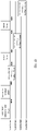
- the beamforming mechanism (IEEE802.11ac/ax respectively) is used for measurement in the related art, such as FIGS. 1A to ID.
- the data transmitting terminal (beamformer) transmits a sounding trigger message frame (a NDP announcement frame), for example, a very high throughput (VHT) NDP announcement frame or a high efficiency (HE) NDP announcement frame.
- VHT very high throughput
- HE high efficiency
- a measurement message frame such as a NDP frame or a beamforming report poll (BFRP) frame is transmitted.
- the data receiving terminal (beamformee) transmits a measurement message feedback frame for feedback, such as a high efficiency compressed beamforming/channel quality indicator (CQI).
- CQI high efficiency compressed beamforming/channel quality indicator
- one data transmitting device transmits an NDP announcement frame, for example, an AP transmits an NDP announcement frame and an NDP frame.
- One or more STAs receive the NDP frame and transmit respectively one or more measurement message feedback frames for feedback.
- APs and STAs that exchange data at the same time, that is, there may be beamformers and beamformees.
- beamformers APs
- STAs beamformees
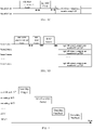
- FIG. 2 is a diagram illustrating a measurement protocol between APs and STAs according to some embodiments.
- a coordinator AP transmits a sounding trigger message frame (Sounding Trigger).
- Sounding Trigger Sounding Trigger
- a sounding AP2 and a sounding AP3 receive the Sounding Trigger and transmit a Joint Sounding Packet.
- the STA that receives the Joint Sounding Packet can transmit a Sounding Feedback for feedback.
- a device that is used as a data transmitting device such as an AP
- the generated measurement message frame includes long training fields (LTF).
- LTF long training fields
- a number of the LTFs is determined based on a number of antennas of AP(s), which can also be understood as determining the number of the LTFs based on a number of spatial streams (SS). Therefore, determining the measurement message frames for the APs is realized.
- the APs transmit the measurement message frames and the STA that receives the measurement message frames transmitted by the APs can transmit a measurement message feedback frame for feedback, thereby realizing the measurement protocol between the APs and the STAs.
- FIG. 3 is a flowchart illustrating a transmission measurement method according to some embodiments. As illustrated in FIG. 3 , the transmission measurement method applicable to the AP includes the following.
- the measurement message frame generated by the AP in the disclosure includes LTFs determined according to a number of APs.
- the measurement message frame is transmitted.
- Each of the APs in embodiments of the disclosure may generate and transmit the measurement message frame in the above-mentioned manner.
- the STA or the AP that has received the measurement message frames transmitted by the APs can transmit a measurement message feedback frame for feedback and complete the transmission measurement.
- FIG. 4 is a flowchart illustrating a transmission measurement method according to some embodiments.
- the transmission measurement method is applicable to a device that receives the measurement message frames, for example, an AP or an STA, which includes the following.
- the measurement message frame received includes LTFs.
- a number of the LTFs is determined based on a number of antennas at AP(s).
- the measurement message frames transmitted and received between the APs and the STAs include the LTFs, and the number of the LTFs is determined based on the number of antennas of the AP(s).
- the transmission measurement between the APs and the STAs may be realized.
- the measurement message frame further includes an identification bit for characterizing whether measurement message frames are transmitted sequentially or jointly.
- the identification bit is a bit, in which a first value of the bit represents the sequential transmission of the measurement message frames and a second value of the bit represents the joint transmission of the measurement message frames.
- the identification bit is one bit, "1" represents the joint transmission of the measurement message frames and "0" represents the sequential transmission of the measurement message frames.
- the number of the LTEs is the number of the antennas of the AP. For example, if the number of antennas of AP1 is 4, the number of the LTFs is 4. If the number of antennas of AP2 is 8, the number of the LTFs is 8.
- the number of the LTFs is a total number of antennas of all APs for the joint transmission or a number of antennas of an AP with a largest number of antennas among all APs for the joint transmission. For example, if the number of antennas of AP1 is 4 and the number of antennas of AP2 is 8, the number of the LTFs is 12 or the number of the LTFs is 8.
- FIG. 5 is a schematic diagram illustrating a format of a measurement message frame according to some embodiments.
- the format of the measurement message frame is successively a legacy-short training field (L-STF) which occupies 8 ⁇ s, a legacy-long training field (L-LTF) which occupies 8 ⁇ s, a legacy-signal (L-SIG) which occupies 4 ⁇ s, a repeated legacy-signal (RL-SIG) which occupies 4 ⁇ s, a signal (SIG) which occupies 8 ⁇ s, a STF which occupies 4 ⁇ s, and a LTF which occupies 7.2 ⁇ s or 8 ⁇ s.
- L-STF legacy-short training field
- L-LTF legacy-long training field
- L-SIG legacy-signal
- RL-SIG repeated legacy-signal
- SIG signal
- the measurement message frame may be triggered to be transmitted by a trigger message frame.
- the trigger message frame may also be referred to as a "trigger frame", which may be understood as the aforementioned Sounding Trigger and NDP announcement frame.
- FIG. 6 is a flowchart illustrating a transmission measurement method according to some embodiments.
- the transmission measurement method is applicable to an AP and includes the following.
- a trigger message frame is received, in which the trigger message frame includes all AP information and all STA information in a designated multicast address.
- the trigger message frame may be transmitted by the coordinator AP.
- the AP that receives the trigger message frame generates a measurement message frame.
- the measurement message frame is transmitted.
- the AP that receives the measurement message frame in embodiments of the disclosure may also serve as the coordinator AP to transmit the trigger message frame.
- FIG. 7 is a flowchart illustrating a transmission measurement method according to some embodiments.
- the transmission measurement method is applicable to an AP and includes the following.
- a trigger message frame is transmitted, in which the trigger message frame includes all AP information and all STA information in a designated multicast address.
- measurement message frames from APs are received, in which the measurement message frame transmitted by AP includes LTFs.
- a number of the LTFs is determined based on a number of antennas at AP(s).
- FIG. 8 is a schematic diagram illustrating a format of a trigger message frame according to some embodiments.
- the trigger message frame includes frame control, duration, receiver address, transport address, common info, user info and slave AP info.
- the receiver address is the multicast address.
- the user info and slave AP info are all slave AP information and all STA information in the multicast address in the receiver address.
- the STA information includes an AP identifier and an association identifier (AID).
- the AP identifier is a basic service set identifier (BSSID) or a service set identifier (SSID).
- BSSID basic service set identifier
- SSID service set identifier
- the BSSID can be 48 bits.
- the BSSID may be a BSSID of a slave AP or a BSSID of an AP that transmits the trigger message frame.
- the AP identifier may be an identifier assigned to a slave AP by an AP that transmits the trigger message frame, which may be a 16-bit identifier and is different from the BSSID.
- the AID is a unique identifier in a basic service set (BSS) which is assigned by the AP to the STA during the association process.
- BSS basic service set
- the STA information further includes a number of resource units (RU), or a number of spatial streams, or a number of RUs and a number of spatial streams.
- the number of the RUs may be a number of RUs allocated by the STA under a certain bandwidth, which is identified by RU allocation.
- SS allocation including a starting stream and a number of streams, means that communication channels are measured.
- the slave AP information includes an AP identifier.
- the AP identifier can be a BSSID or an identifier assigned by an AP that transmits the trigger frame.
- the transmission measurement method provided in embodiments of the disclosure is applicable to a process of data exchange between the APs and the STAs.
- the APs and the STAs involved in the foregoing embodiments are applied to implement the process of transmission measurement, which may refer to the relevant description of the foregoing embodiments and will not be described in detail herein.
- the format of the trigger message frame and the format of the measurement message frame are suitable for the transmission measurement before the data exchange between the APs and the STAs.
- the trigger message frame includes all AP information and all STA information in the designated multicast address and can trigger the APs or the STAs to transmit the trigger message frame.
- the trigger message frame includes the LTFs determined based on the number of antennas of the AP(s) or STA(s). The transmission measurement for the APs and the STAs may be realized.
- embodiments of the disclosure also provide a transmission measurement apparatus.
- the transmission measurement apparatus includes hardware structures and/or software modules for performing each function to realize the above-mentioned functions.
- embodiments of the disclosure can be implemented in a form of hardware or a combination of hardware and computer software. Whether a certain function is executed by hardware or software-driven hardware depends on specific applications and design constraint conditions of the technical solutions. Those skilled in the art can use different methods for each specific application to implement the described functions, but such implementation should not be considered as going beyond the scope of the technical solutions of embodiments of the disclosure.
- FIG. 9 is a block diagram illustrating a transmission measurement apparatus according to some embodiments.
- the transmission measurement apparatus 100 includes a generating unit 101 and a transmitting unit 102.
- the generating unit 101 is configured to generate a measurement message frame that does not include a data part, in which the measurement message frame includes LTFs and a number of the LTFs is determined based on a number of antennas of an AP.
- the transmitting unit 102 is configured to transmit the measurement message frame.
- the measurement message frame further includes an identification bit for characterizing sequential transmission; and the number of the LTFs is the number of the antennas of the AP.
- the measurement message frame further includes an identification bit for characterizing joint transmission; and the number of the LTFs is a total number of antennas of all APs for the joint transmission.
- the measurement message frame further includes an identification bit for characterizing joint transmission; and the number of the LTFs is a number of antennas of an AP with a largest number of antennas among all APs for the joint transmission.
- the apparatus further includes: a receiving unit 103 configured to receive a trigger message frame, in which the trigger message frame includes all AP information and all STA information in a designated multicast address.
- the STA information includes an AP identifier and an AID.
- the AP identifier is a BSSID.
- the BSSID is a BSSID of a slave AP or a BSSID of an AP that transmits the trigger message frame.
- the AP identifier is an identifier assigned to a slave AP by an AP that transmits the trigger message frame.
- the STA information further includes a number of resource units, or a number of spatial streams, or a number of resource units and a number of spatial streams.
- the AP information includes an AP identifier.
- FIG. 10 is a block diagram illustrating a transmission measurement apparatus according to some embodiments.
- the transmission measurement apparatus 200 includes a receiving unit 201 and a transmitting unit 202.
- the receiving unit 201 is configured to receive measurement message frames from APs, in which the measurement message frame includes LTFs and a number of the LTFs is determined based on a number of antennas of an AP.
- the transmitting unit 202 is configured to transmit a measurement message feedback frame.
- the measurement message frame further includes an identification bit for characterizing sequential transmission; and the number of the LTFs is the number of the antennas of the AP.
- the measurement message frame further includes an identification bit for characterizing joint transmission; and the number of the LTFs is a total number of antennas of all APs for the joint transmission or a number of antennas of an AP with a largest number of antennas among all APs for the joint transmission.
- the transmitting unit 202 is further configured to: transmit a trigger message frame, in which the trigger message frame includes all AP information and all STA information in a designated multicast address.
- the STA information includes an AP identifier and an AID.
- the AP identifier is a BSSID.
- the BSSID is a BSSID of a slave AP or a BSSID of an AP that transmits the trigger message frame.
- the AP identifier is an identifier assigned to a slave AP by an AP that transmits the trigger message frame.
- the STA information further includes a number of resource units, or a number of spatial streams, or a number of resource units and a number of spatial streams.
- the AP information includes an AP identifier.
- FIG. 11 is a block diagram illustrating a transmission measurement device 300 according to some embodiments.
- the device 300 may be an AP, such as a mobile phone, a computer, a digital broadcast terminal, a messaging device, a gaming console, a tablet, a medical device, exercise equipment, a personal digital assistant, and the like.
- AP such as a mobile phone, a computer, a digital broadcast terminal, a messaging device, a gaming console, a tablet, a medical device, exercise equipment, a personal digital assistant, and the like.
- the device 300 may include one or more of the following components: a processing component 302, a memory 304, a power component 306, a multimedia component 308, an audio component 310, an input/output (I/O) interface 312, a sensor component 314, and a communication component 316.
- the processing component 302 typically controls overall operations of the device 300, such as the operations associated with display, telephone calls, data communications, camera operations, and recording operations.
- the processing component 302 may include one or more processors 320 to execute instructions to perform all or part of the actions in the above described methods.
- the processing component 302 may include one or more modules which facilitate the interaction between the processing component 302 and other components.
- the processing component 302 may include a multimedia module to facilitate the interaction between the multimedia component 308 and the processing component 302.
- the memory 304 is configured to store various types of data to support the operation of the device 300. Examples of such data include instructions for any applications or methods operated on the device 300, contact data, phonebook data, messages, pictures, video, etc.
- the memory 304 may be implemented using any type of volatile or non-volatile memory devices, or a combination thereof, such as a static random access memory (SRAM), an electrically erasable programmable read-only memory (EEPROM), an erasable programmable read-only memory (EPROM), a programmable read-only memory (PROM), a read-only memory (ROM), a magnetic memory, a flash memory, a magnetic or optical disk.
- SRAM static random access memory
- EEPROM electrically erasable programmable read-only memory
- EPROM erasable programmable read-only memory
- PROM programmable read-only memory
- ROM read-only memory
- magnetic memory a magnetic memory
- flash memory a flash memory
- magnetic or optical disk a magnetic or optical
- the power component 306 provides power to various components of the device 300.
- the power component 306 may include a power management system, one or more power sources, and any other components associated with the generation, management, and distribution of power in the device 300.
- the multimedia component 308 includes a screen providing an output interface between the device 300 and the user.
- the screen may include a liquid crystal display (LCD) and a touch panel (TP). If the screen includes the touch panel, the screen may be implemented as a touch screen to receive input signals from the user.
- the touch panel includes one or more touch sensors to sense touches, swipes, and gestures on the touch panel. The touch sensors may not only sense a boundary of a touch or swipe action, but also sense a period of time and a pressure associated with the touch or swipe action.
- the multimedia component 308 includes a front camera and/or a rear camera. The front camera and the rear camera may receive an external multimedia datum while the device 300 is in an operation mode, such as a photographing mode or a video mode. Each of the front camera and the rear camera may be a fixed optical lens system or have focus and optical zoom capability.
- the audio component 310 is configured to output and/or input audio signals.
- the audio component 310 includes a microphone ("MIC") configured to receive an external audio signal when the device 300 is in an operation mode, such as a call mode, a recording mode, and a voice recognition mode.
- the received audio signal may be further stored in the memory 304 or transmitted via the communication component 316.
- the audio component 310 further includes a speaker to output audio signals.
- the I/O interface 312 provides an interface between the processing component 302 and peripheral interface modules, such as a keyboard, a click wheel, buttons, and the like.
- the buttons may include, but are not limited to, a home button, a volume button, a starting button, and a locking button.
- the sensor component 314 includes one or more sensors to provide status assessments of various aspects of the device 300. For instance, the sensor component 314 may detect an open/closed status of the device 300, relative positioning of components, e.g., the display and the keypad, of the device 300, a change in position of the device 300 or a component of the device 300, a presence or absence of user contact with the device 300, an orientation or an acceleration/deceleration of the device 300, and a change in temperature of the device 300.
- the sensor component 314 may include a proximity sensor configured to detect the presence of nearby objects without any physical contact.
- the sensor component 314 may also include a light sensor, such as a CMOS or CCD image sensor, for use in imaging applications.
- the sensor component 314 may also include an accelerometer sensor, a gyroscope sensor, a magnetic sensor, a pressure sensor, or a temperature sensor.
- the communication component 316 is configured to facilitate communication, wired or wirelessly, between the device 300 and other devices.
- the device 300 can access a wireless network based on a communication standard, such as WiFi, 2G, or 3G, or a combination thereof.
- the communication component 316 receives a broadcast signal or broadcast associated information from an external broadcast management system via a broadcast channel.
- the communication component 316 further includes a near field communication (NFC) module to facilitate short-range communications.
- the NFC module may be implemented based on a radio frequency identification (RFID) technology, an infrared data association (IrDA) technology, an ultra-wideband (UWB) technology, a Bluetooth (BT) technology, and other technologies.
- RFID radio frequency identification
- IrDA infrared data association
- UWB ultra-wideband
- BT Bluetooth
- the device 300 may be implemented with one or more application specific integrated circuits (ASICs), digital signal processors (DSPs), digital signal processing devices (DSPDs), programmable logic devices (PLDs), field programmable gate arrays (FPGAs), controllers, micro-controllers, microprocessors, or other electronic components, for performing the above described methods.
- ASICs application specific integrated circuits
- DSPs digital signal processors
- DSPDs digital signal processing devices
- PLDs programmable logic devices
- FPGAs field programmable gate arrays
- controllers micro-controllers, microprocessors, or other electronic components, for performing the above described methods.
- non-transitory computer-readable storage medium including instructions, such as included in the memory 304, executable by the processor 320 in the device 300, for performing the above-described methods.
- the non-transitory computer-readable storage medium may be a ROM, a RAM, a CD-ROM, a magnetic tape, a floppy disc, an optical data storage device, and the like.
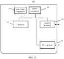
- FIG. 12 is a block diagram illustrating a transmission measurement device 400 according to some embodiments.
- the device 400 may be a STA or an AP.
- the device 400 may include a processing component 422 which further includes one or more processors, and a memory resource represented by a memory 432 for storing instructions such as an application program that can be executed by the processing component 422.
- the application program stored in the memory 432 may include one or more modules each corresponding to a set of instructions.
- the processing component 422 is configured to execute instructions to perform the above-mentioned methods.
- the device 400 may also include a power component 426 configured to perform power management of the device 400, a wired or wireless network interface 450 configured to connect the device 400 to a network, and an input/output (I/O) interface 458.
- the device 400 can operate based on an operating system stored in the memory 432, such as Windows Server TM , Mac OS X TM , Unix TM , Linux TM , FreeBSD TM or the like.
- plural or “multiple” in the disclosure may refer to two or more, and other quantifiers are similar.
- the term “and/or” may describe association relationships of associated objects, indicating that there may be three types of relationships, for example, A and/or B, which may mean: A exists alone, A and B exist at the same time, and B exists alone.
- the character “/” generally indicates that the associated objects before and after are in an “or” relationship.
- the singular forms of "a”, “said” and “the” are also intended to include plural forms, unless the context clearly indicates other meanings.
- first, second, and the like may be used to describe various information, the information should not be limited to these terms. These terms are only used to distinguish the same type of information from each other, and do not indicate a specific order or degree of importance. In fact, expressions such as “first” and “second” can be used interchangeably.
- first information may also be referred to as the second information
- second information may also be referred to as the first information.
Landscapes
- Engineering & Computer Science (AREA)
- Computer Networks & Wireless Communication (AREA)
- Signal Processing (AREA)
- Physics & Mathematics (AREA)
- Electromagnetism (AREA)
- Power Engineering (AREA)
- Mobile Radio Communication Systems (AREA)
Applications Claiming Priority (1)
| Application Number | Priority Date | Filing Date | Title |
|---|---|---|---|
| PCT/CN2019/124125 WO2021114053A1 (zh) | 2019-12-09 | 2019-12-09 | 传输测量方法、传输测量装置及存储介质 |
Publications (2)
| Publication Number | Publication Date |
|---|---|
| EP4075853A1 true EP4075853A1 (de) | 2022-10-19 |
| EP4075853A4 EP4075853A4 (de) | 2023-08-30 |
Family
ID=76329222
Family Applications (1)
| Application Number | Title | Priority Date | Filing Date |
|---|---|---|---|
| EP19955920.4A Pending EP4075853A4 (de) | 2019-12-09 | 2019-12-09 | Übertragungsmessverfahren, übertragungsmessvorrichtung und speichermedium |
Country Status (4)
| Country | Link |
|---|---|
| US (1) | US12348998B2 (de) |
| EP (1) | EP4075853A4 (de) |
| CN (1) | CN113261324B (de) |
| WO (1) | WO2021114053A1 (de) |
Families Citing this family (2)
| Publication number | Priority date | Publication date | Assignee | Title |
|---|---|---|---|---|
| CN114938715B (zh) * | 2022-04-15 | 2025-07-15 | 北京小米移动软件有限公司 | 通信方法和通信装置 |
| US12581344B2 (en) * | 2023-03-31 | 2026-03-17 | Cisco Technology, Inc. | Multiple access point WiFi sounding |
Family Cites Families (25)
| Publication number | Priority date | Publication date | Assignee | Title |
|---|---|---|---|---|
| CN102201891B (zh) | 2011-05-03 | 2015-07-22 | 中兴通讯股份有限公司 | 一种无线帧的发送方法和装置 |
| KR102005055B1 (ko) * | 2011-05-26 | 2019-07-29 | 마벨 월드 트레이드 리미티드 | 장거리 wlan을 위한 사운딩 패킷 포맷 |
| CN104904292B (zh) * | 2012-11-08 | 2019-09-13 | 交互数字专利控股公司 | 用于无线局域网中的统一的多个接入点覆盖的介质访问控制方法和装置 |
| US10027512B2 (en) * | 2014-01-06 | 2018-07-17 | Lg Electronics Inc. | Method and apparatus for sounding in wireless communication system |
| US10111132B2 (en) * | 2015-03-02 | 2018-10-23 | Qualcomm Incorporated | Methods and apparatus for channel state information sounding and feedback |
| RU2683957C1 (ru) | 2015-07-02 | 2019-04-03 | Хуавэй Текнолоджиз Ко., Лтд. | Способ, точка доступа и станция для передачи информации о состоянии канала |
| WO2017007266A1 (ko) * | 2015-07-07 | 2017-01-12 | 엘지전자 주식회사 | 무선랜 시스템에서 사운딩 동작 방법 및 이를 위한 장치 |
| WO2017030295A1 (ko) * | 2015-08-19 | 2017-02-23 | 엘지전자(주) | 무선 통신 시스템에서 채널 상태의 피드백 방법 및 이를 위한 장치 |
| JP6619311B2 (ja) * | 2015-10-30 | 2019-12-11 | 株式会社東芝 | 無線通信装置および無線通信方法 |
| CN107027145B (zh) * | 2016-02-01 | 2021-01-01 | 华为技术有限公司 | 信道测量方法及装置 |
| US10200097B2 (en) * | 2016-03-28 | 2019-02-05 | Qualcomm Incorporated | Enhanced antenna array training |
| US11083021B2 (en) * | 2016-04-14 | 2021-08-03 | Qualcomm Incorporated | Random access resource unit allocation for a multiple BSSID network |
| CN107979402B (zh) * | 2016-10-25 | 2020-09-08 | 华为技术有限公司 | 一种信道状态信息测量方法及装置 |
| US10924955B2 (en) * | 2016-11-18 | 2021-02-16 | Lg Electronics Inc. | Method for reporting channel information in wireless LAN system and device therefor |
| WO2018156211A1 (en) * | 2017-02-21 | 2018-08-30 | Intel IP Corporation | Control fields for null data packet feedback reports |
| US10462816B2 (en) * | 2017-04-17 | 2019-10-29 | Qualcomm Incorporated | Trigger-based random access in a multiple BSSID network |
| US10928505B1 (en) * | 2017-05-12 | 2021-02-23 | Marvell Asia Pte, Ltd. | Null data packet (NDP) announcement frame and trigger frame for NDP ranging |
| US10454538B2 (en) | 2017-09-08 | 2019-10-22 | Qualcomm Incorporated | Methods and systems for joint access point MIMO transmissions |
| CN109714092B (zh) * | 2017-10-26 | 2021-09-07 | 华为技术有限公司 | 用于传输数据的方法和装置 |
| US11051174B2 (en) * | 2018-08-17 | 2021-06-29 | Intel Corporation | Grouping of access points (AP) into multi-AP groups to enable coordination of downlink transmissions |
| EP4676148A3 (de) * | 2018-11-08 | 2026-03-18 | InterDigital Patent Holdings, Inc. | Verfahren und vorrichtung für gemeinsame multi-ap-übertragung in wlans |
| US10986600B1 (en) * | 2018-12-05 | 2021-04-20 | Nxp Usa, Inc. | Timing synchronization for multi-user (MU) ranging measurements in a wireless local area network (WLAN) |
| US11108439B2 (en) * | 2019-04-22 | 2021-08-31 | Mediatek Singapore Pte. Ltd. | Device and method for multi-access point collaborative sounding in a wireless network |
| US11641633B1 (en) * | 2019-09-06 | 2023-05-02 | Marvell Asia Pte Ltd | Synchronization of joint transmissions with multiple access points |
| US11716121B2 (en) * | 2019-10-25 | 2023-08-01 | Intel Corporation | NDPA for multi-AP coordinated beamforming (CBF) and multi-AP joint transmission (JT) in EHT |
-
2019
- 2019-12-09 EP EP19955920.4A patent/EP4075853A4/de active Pending
- 2019-12-09 US US17/783,242 patent/US12348998B2/en active Active
- 2019-12-09 CN CN201980003484.6A patent/CN113261324B/zh active Active
- 2019-12-09 WO PCT/CN2019/124125 patent/WO2021114053A1/zh not_active Ceased
Also Published As
| Publication number | Publication date |
|---|---|
| US20230012708A1 (en) | 2023-01-19 |
| EP4075853A4 (de) | 2023-08-30 |
| WO2021114053A1 (zh) | 2021-06-17 |
| US12348998B2 (en) | 2025-07-01 |
| CN113261324A (zh) | 2021-08-13 |
| CN113261324B (zh) | 2023-07-25 |
Similar Documents
| Publication | Publication Date | Title |
|---|---|---|
| US20210336737A1 (en) | Measurement configuration method, apparatus, devices, system, and storage medium | |
| CN113170390A (zh) | 设备省电方法及设备省电装置 | |
| EP4231741B1 (de) | Verfahren und vorrichtung zur koordination von drahtloserfassungsressourcen und speichermedium | |
| CN113841445B (zh) | 数据传输方法、数据传输装置及存储介质 | |
| US12348998B2 (en) | Transmission measurement method, transmission measurement device and storage medium | |
| US20230095649A1 (en) | Beam determination method and apparatus, and communication device | |
| WO2021179179A1 (zh) | 传输数据的方法、装置、通信设备及存储介质 | |
| WO2023155106A1 (zh) | 信道状态指示反馈信息传输方法、通信设备和存储介质 | |
| WO2021159516A1 (zh) | 初始接入方法、初始接入装置及存储介质 | |
| US12432741B2 (en) | Resource allocation method, resource allocation apparatus and storage medium | |
| US12401470B2 (en) | Method and device for allocating communication resources, and method and device for transmitting data | |
| CN113383596B (zh) | 网络分配向量的确定方法、装置及存储介质 | |
| US12177138B2 (en) | Method, device and storage medium for transmitting data | |
| US20240357558A1 (en) | Communication method, user equipment, and network device | |
| WO2022151387A1 (zh) | 信息动态指示方法及装置、网络设备、用户设备及存储介质 | |
| CN113383601A (zh) | 数据帧传输方法、数据帧传输装置及存储介质 | |
| US12302165B2 (en) | Method for transmitting data, communication device, and storage medium | |
| EP4727235A1 (de) | Informationsverarbeitungsverfahren und -vorrichtung, kommunikationsvorrichtung und speichermedium | |
| CN113261241B (zh) | 重关联指示方法、装置及通信设备 | |
| CN112789806B (zh) | 数据传输方法、装置及存储介质 | |
| US12155466B2 (en) | Data transmission method and apparatus, and communication device and storage medium | |
| US20230396399A1 (en) | Information transmission method, communication device and storage medium | |
| US20230269773A1 (en) | Communication method, communication device and storage medium | |
| WO2024212062A1 (zh) | 调度方法以及装置、通信设备及存储介质 | |
| WO2021056288A1 (zh) | 接收反馈信息传输配置方法、装置、通信设备及存储介质 |
Legal Events
| Date | Code | Title | Description |
|---|---|---|---|
| STAA | Information on the status of an ep patent application or granted ep patent |
Free format text: STATUS: THE INTERNATIONAL PUBLICATION HAS BEEN MADE |
|
| PUAI | Public reference made under article 153(3) epc to a published international application that has entered the european phase |
Free format text: ORIGINAL CODE: 0009012 |
|
| STAA | Information on the status of an ep patent application or granted ep patent |
Free format text: STATUS: REQUEST FOR EXAMINATION WAS MADE |
|
| 17P | Request for examination filed |
Effective date: 20220707 |
|
| AK | Designated contracting states |
Kind code of ref document: A1 Designated state(s): AL AT BE BG CH CY CZ DE DK EE ES FI FR GB GR HR HU IE IS IT LI LT LU LV MC MK MT NL NO PL PT RO RS SE SI SK SM TR |
|
| DAV | Request for validation of the european patent (deleted) | ||
| DAX | Request for extension of the european patent (deleted) | ||
| REG | Reference to a national code |
Ref country code: DE Ref legal event code: R079 Free format text: PREVIOUS MAIN CLASS: H04W0024000000 Ipc: H04W0084120000 |
|
| A4 | Supplementary search report drawn up and despatched |
Effective date: 20230727 |
|
| RIC1 | Information provided on ipc code assigned before grant |
Ipc: H04B 17/24 20150101ALI20230721BHEP Ipc: H04L 25/02 20060101ALI20230721BHEP Ipc: H04B 7/06 20060101ALI20230721BHEP Ipc: H04W 84/12 20090101AFI20230721BHEP |
|
| STAA | Information on the status of an ep patent application or granted ep patent |
Free format text: STATUS: EXAMINATION IS IN PROGRESS |
|
| 17Q | First examination report despatched |
Effective date: 20250325 |