EP4075778B1 - Raster image processor - Google Patents
Raster image processor Download PDFInfo
- Publication number
- EP4075778B1 EP4075778B1 EP22171731.7A EP22171731A EP4075778B1 EP 4075778 B1 EP4075778 B1 EP 4075778B1 EP 22171731 A EP22171731 A EP 22171731A EP 4075778 B1 EP4075778 B1 EP 4075778B1
- Authority
- EP
- European Patent Office
- Prior art keywords
- spiral
- raster image
- halftone
- dots
- image processor
- Prior art date
- Legal status (The legal status is an assumption and is not a legal conclusion. Google has not performed a legal analysis and makes no representation as to the accuracy of the status listed.)
- Active
Links
Images









Classifications
-
- H—ELECTRICITY
- H04—ELECTRIC COMMUNICATION TECHNIQUE
- H04N—PICTORIAL COMMUNICATION, e.g. TELEVISION
- H04N1/00—Scanning, transmission or reproduction of documents or the like, e.g. facsimile transmission; Details thereof
- H04N1/40—Picture signal circuits
- H04N1/405—Halftoning, i.e. converting the picture signal of a continuous-tone original into a corresponding signal showing only two levels
-
- B—PERFORMING OPERATIONS; TRANSPORTING
- B41—PRINTING; LINING MACHINES; TYPEWRITERS; STAMPS
- B41C—PROCESSES FOR THE MANUFACTURE OR REPRODUCTION OF PRINTING SURFACES
- B41C1/00—Forme preparation
- B41C1/02—Engraving; Heads therefor
-
- B—PERFORMING OPERATIONS; TRANSPORTING
- B41—PRINTING; LINING MACHINES; TYPEWRITERS; STAMPS
- B41C—PROCESSES FOR THE MANUFACTURE OR REPRODUCTION OF PRINTING SURFACES
- B41C1/00—Forme preparation
- B41C1/10—Forme preparation for lithographic printing; Master sheets for transferring a lithographic image to the forme
-
- B—PERFORMING OPERATIONS; TRANSPORTING
- B41—PRINTING; LINING MACHINES; TYPEWRITERS; STAMPS
- B41J—TYPEWRITERS; SELECTIVE PRINTING MECHANISMS, i.e. MECHANISMS PRINTING OTHERWISE THAN FROM A FORME; CORRECTION OF TYPOGRAPHICAL ERRORS
- B41J2/00—Typewriters or selective printing mechanisms characterised by the printing or marking process for which they are designed
- B41J2/005—Typewriters or selective printing mechanisms characterised by the printing or marking process for which they are designed characterised by bringing liquid or particles selectively into contact with a printing material
- B41J2/01—Ink jet
- B41J2/205—Ink jet for printing a discrete number of tones
- B41J2/2054—Ink jet for printing a discrete number of tones by the variation of dot disposition or characteristics, e.g. dot number density, dot shape
-
- B—PERFORMING OPERATIONS; TRANSPORTING
- B41—PRINTING; LINING MACHINES; TYPEWRITERS; STAMPS
- B41M—PRINTING, DUPLICATING, MARKING, OR COPYING PROCESSES; COLOUR PRINTING
- B41M1/00—Inking and printing with a printer's forme
- B41M1/02—Letterpress printing, e.g. book printing
- B41M1/04—Flexographic printing
-
- B—PERFORMING OPERATIONS; TRANSPORTING
- B41—PRINTING; LINING MACHINES; TYPEWRITERS; STAMPS
- B41M—PRINTING, DUPLICATING, MARKING, OR COPYING PROCESSES; COLOUR PRINTING
- B41M1/00—Inking and printing with a printer's forme
- B41M1/06—Lithographic printing
-
- B—PERFORMING OPERATIONS; TRANSPORTING
- B41—PRINTING; LINING MACHINES; TYPEWRITERS; STAMPS
- B41M—PRINTING, DUPLICATING, MARKING, OR COPYING PROCESSES; COLOUR PRINTING
- B41M5/00—Duplicating or marking methods; Sheet materials for use therein
- B41M5/0041—Digital printing on surfaces other than ordinary paper
- B41M5/0047—Digital printing on surfaces other than ordinary paper by ink-jet printing
-
- B—PERFORMING OPERATIONS; TRANSPORTING
- B41—PRINTING; LINING MACHINES; TYPEWRITERS; STAMPS
- B41N—PRINTING PLATES OR FOILS; MATERIALS FOR SURFACES USED IN PRINTING MACHINES FOR PRINTING, INKING, DAMPING, OR THE LIKE; PREPARING SUCH SURFACES FOR USE AND CONSERVING THEM
- B41N1/00—Printing plates or foils; Materials therefor
- B41N1/12—Printing plates or foils; Materials therefor non-metallic other than stone, e.g. printing plates or foils comprising inorganic materials in an organic matrix
-
- B—PERFORMING OPERATIONS; TRANSPORTING
- B41—PRINTING; LINING MACHINES; TYPEWRITERS; STAMPS
- B41N—PRINTING PLATES OR FOILS; MATERIALS FOR SURFACES USED IN PRINTING MACHINES FOR PRINTING, INKING, DAMPING, OR THE LIKE; PREPARING SUCH SURFACES FOR USE AND CONSERVING THEM
- B41N1/00—Printing plates or foils; Materials therefor
- B41N1/12—Printing plates or foils; Materials therefor non-metallic other than stone, e.g. printing plates or foils comprising inorganic materials in an organic matrix
- B41N1/14—Lithographic printing foils
-
- B—PERFORMING OPERATIONS; TRANSPORTING
- B41—PRINTING; LINING MACHINES; TYPEWRITERS; STAMPS
- B41N—PRINTING PLATES OR FOILS; MATERIALS FOR SURFACES USED IN PRINTING MACHINES FOR PRINTING, INKING, DAMPING, OR THE LIKE; PREPARING SUCH SURFACES FOR USE AND CONSERVING THEM
- B41N1/00—Printing plates or foils; Materials therefor
- B41N1/16—Curved printing plates, especially cylinders
- B41N1/22—Curved printing plates, especially cylinders made of other substances
-
- G—PHYSICS
- G06—COMPUTING OR CALCULATING; COUNTING
- G06K—GRAPHICAL DATA READING; PRESENTATION OF DATA; RECORD CARRIERS; HANDLING RECORD CARRIERS
- G06K15/00—Arrangements for producing a permanent visual presentation of the output data, e.g. computer output printers
- G06K15/02—Arrangements for producing a permanent visual presentation of the output data, e.g. computer output printers using printers
- G06K15/18—Conditioning data for presenting it to the physical printing elements
- G06K15/1835—Transforming generic data
- G06K15/1836—Rasterization
-
- G—PHYSICS
- G06—COMPUTING OR CALCULATING; COUNTING
- G06K—GRAPHICAL DATA READING; PRESENTATION OF DATA; RECORD CARRIERS; HANDLING RECORD CARRIERS
- G06K15/00—Arrangements for producing a permanent visual presentation of the output data, e.g. computer output printers
- G06K15/02—Arrangements for producing a permanent visual presentation of the output data, e.g. computer output printers using printers
- G06K15/18—Conditioning data for presenting it to the physical printing elements
- G06K15/1867—Post-processing of the composed and rasterized print image
- G06K15/1872—Image enhancement
- G06K15/1881—Halftoning
-
- B—PERFORMING OPERATIONS; TRANSPORTING
- B41—PRINTING; LINING MACHINES; TYPEWRITERS; STAMPS
- B41M—PRINTING, DUPLICATING, MARKING, OR COPYING PROCESSES; COLOUR PRINTING
- B41M3/00—Printing processes to produce particular kinds of printed work, e.g. patterns
Definitions
- the invention relates to the field of raster image processors wherein digital halftoning methods are used for printing images, in particular by means of lithographic or flexographic printing presses, and by digital printing techniques such as inkjet printing.
- Digital halftoning is the process of rendering the illusion of a continuous-tone image with a number of dots, also called halftone dots.
- the digital image produced by digital halftoning is called a halftone raster image or screen. Both multilevel and binary halftoning methods are known.
- the halftone dots produced by binary methods consist of pixels which represent image data and pixels which represent non-image data.
- Binary digital halftoning is a well-known technique, which is explained in detail by Robert Ulichney in his book “Digital Halftoning", MIT Press, 1987, ISBN 0-262-21009-6 , wherein chapter 5 about 'clustered-dot ordered dither' is background art for the present invention including the use of threshold tiles for rendering continuous-tone images.
- AM (amplitude modulated) screening is a widely used clustered-dot-ordered dithering technique wherein the size of the halftone dots is modulated in order to represent different densities of an image.
- each halftone dot corresponds to a certain amount of ink, called further a blob, which has to be pressed or jetted onto the substrate to be printed, dried and cured in a (very) short time, which may especially produce problems when printing with multiple inks on top of each other, whether wet-on-wet or wet-on-(semi)dry.
- Hybrid screening techniques are available which combine AM and FM methods so as to obtain the advantages of both.
- Said screening techniques however involve the use of multiple threshold tiles for rendering a continuous-tone image, which requires more memory space to store these multiple threshold tiles, for example a threshold tile with FM method in the highlights, a threshold tile with AM method in the midtones and another threshold tile with FM method in the shadows.
- the transitions from one threshold tile to another may produce density jumps in the printed image whereby calibration of said screening techniques also takes more service time than AM and FM.
- US2007/0002384 discloses a method of controlling thickness of an ink blob in an AM halftone region of a printing plate or an intermediate image carrier on a digital press.
- the method generates a raster image with regularly tiled halftone dots, which comprise one or more ink-receptive rings enclosing a non-receptive portion.
- the ink-receptive rings form a closed loop, which completely encloses the portion that does not accept ink; as a result, the extent at which the ink can spread within the dot remains limited because no further spreading of the ink within the dot is possible as soon as the enclosed portion is filled.
- the raster image processor of claim 1 for transforming information of a page to a halftone raster having halftone dots, wherein the halftone dots comprise, with reference to FIG.36 :
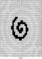
- Such dots will be referred to herein as "spiral dots".
- the image pixels are represented by the black areas in the figures.
- the non-image pixels define non-printing areas and correspond to the empty space that is left in the dot as represented by the white areas in the figures.
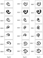
- the two dots at the left hand side of FIG.36 have a low dot coverage (low percentage of image pixels) and represent highlights of an image, while the two dots at the right hand side of FIG.36 have a high dot coverage and represent shadows of said image.
- the image pixels define areas of the image which is to be printed, typically with ink, e.g. by a printing press or an inkjet printer, or with toner, e.g. in a laser printer.
- ink typically with ink
- toner e.g. in a laser printer.
- the number of image pixels per dot is low so that they cannot form a complete winding of the first spiral but just a section thereof, which is referred to as the "first arc".
- the empty space which is partially enclosed by the first arc also may be considered as another arc, which is referred to herein as the "second arc”.
- the number of image pixels per dot is higher so that they can form one or more windings of the "first spiral", thereby also defining a "second spiral" of non-image pixels defined by the empty space between the windings of the first spiral (see e.g. FIG.10 ).
- the shape and size of the printed ink blob is less affected by uncontrolled spreading of the ink because, when the ink blob is pressed onto the substrate, e.g. by a printing press, the excess ink that is printed by the first arc or first spiral can flow into the empty space that corresponds to the second arc or second spiral.
- the empty space defines an ink channel that can accept ink, which is printed from the first arc/spiral, thereby providing means for controlling the spreading of the ink.
- the empty arcs used in the spiral dots of our invention can be connected to one another (thereby forming the second spiral), so that the ink blob has more room to spread within the dot.
- the raster image of the present invention produces well-shaped ink dots on the printed substrate, resulting in an improved quality of the reproduced images and less dot gain, which is especially advantageous when printing on absorbent, uncoated paper stock such as newsprint.
- our invention allows to obtain a good print quality with less ink consumption than conventional techniques because the excess ink that is sitting on top of a printed blob, when printed with a conventional raster image, contributes to the density of the printed image by filling the empty space formed by the second arc or the second spiral.
- the lower extent of local ink accumulation produces thinner ink drops on the printed substrate and therefor enables faster drying of the printed copies.
- the second spiral is open-ended, i.e. not terminated by image pixels at the outer edge of the halftone dot, so that it forms an open channel that can guide excess ink out of the dot.
- Magnified images of printed dots produced by this embodiment typically show the release of a small quantity of ink at the outlet of the channel, i.e. outside the dot.
- the open channel enables a further spreading of the ink and, as a result, more ink saving and still faster drying.
- raster image of our invention can be produced by a single threshold tile for the full range of density values per colour, such as cyan, magenta, yellow or black, so that it can be implemented without installing additional memory in current image processors, prepress workflow systems and raster image processors (RIP's), digital printers and plate setters.
- RIP's raster image processors
- the rendering of higher image densities in the highlights and mid-tones of the image can be realised simply by growing the length of the first spiral by adding more arcs to it, thereby producing more windings of the first spiral around the centre of the dot (and, as a result, also more windings of the second spiral).
- Higher image densities can also be obtained by increasing the thickness of the first spiral.
- Both embodiments can be combined in the same image, i.e. the image density of the halftone dot can be increased by growing the length and by increasing the thickness of the first spiral. In the shadows of the image, where the halftone dots touch or even overlap, higher image densities can be obtained by shrinking the length and/or thickness of the second spiral.
- the halftone raster image of our invention is preferably used in lithographic and flexographic printing systems.
- the present invention also provides advantages when used in combination with digital printers, in particular inkjet systems.
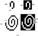
- the halftone raster image for rendering a continuous-tone image comprises a plurality of halftone dots which comprise (i) image pixels arranged as a first arc (200) or as a plurality of arcs which together represent a first spiral (100), and (ii) non-image pixels arranged as a second arc (201) or as a plurality of arcs which together represent a second spiral (101).
- the second arc or second spiral is preferably open-ended.
- the thickness of said first and second arc and said first and second spiral is preferably independently from 1 ⁇ m to 75 ⁇ m and/or the halftone dots are regularly tiled at a distance between centres of neighbouring halftone dots from 50 ⁇ m to 400 ⁇ m.
- the halftone raster image has preferably a screen frequency above 39 lines per cm and a screen angle selected from the group consisting of 0°, 15°, 75°, 90°, 45°, 67.5°, 22.5°, 7.5°, 82.5° and 37.5° and/or preferably screen frequency is higher than 40 lines per inch (15.7 lines/cm).
- An embodiment of the present invention is a lithographic printing plate comprising the embodiment and preferred embodiments of halftone raster images wherein the first spiral defines ink accepting areas and the second spiral defines water accepting areas and in another preferred embodiment a flexographic printing plate comprising said halftone raster image wherein the first spiral defines ink accepting areas.
- An embodiment of the present invention is transforming a continuous-tone image to the embodiment and preferred embodiments of the halftone raster image wherein the first arc, the first spiral, the second arc and the second spiral of the spiral dots each have a length and/or a thickness which is determined by local densities of the continuous-tone image, the method comprising the step of transforming said continuous-tone image to said halftone raster image by means of at least one threshold tile, whereby
- An embodiment of the present invention is making a printing plate comprising the steps of (i) making the embodiment and preferred embodiments of the halftone raster image and (ii) exposing said halftone raster image on a printing plate precursor.
- Said embodiment may be part of an embodiment of printing which has a third step (iii): transferring ink from said plate to a substrate.
- a halftone dot is a picture element of a screen, and can be e.g. circular-, elliptical-, diamond- or square-shaped. In the highlights and midtones of the image, the halftone dots are isolated from one another, while above a coverage of approximately 50% the dots connect with each other.
- a screen also called halftone raster image
- a screen is an area broken down into printing and non-printing picture elements (halftone dots or lines) wherein the size and/or number of dots per area varies according to the tone values (also called density) of the original such as a continuous-tone image.
- Screening also called halftoning, is the method whereby a continuous-tone image is transformed into a halftone raster image or a set of halftone raster images.
- the transformation may involve the use of one or more threshold tiles.
- the number of threshold tiles depends normally on the number of colour channels comprised in the continuous-tone image.
- a continuous-tone (digital) image is defined by various image formats, also called raster graphics format, of which non-limiting examples are Portable Network Graphics (PNG), Tagged Image File Format (TIFF), Adobe Photoshop Document (PSD), Joint Photographic Experts Group (JPEG) and bitmap (BMP).
- PNG Portable Network Graphics
- TIFF Tagged Image File Format
- PSD Adobe Photoshop Document
- JPEG Joint Photographic Experts Group
- BMP bitmap
- a continuous-tone image typically has a large colour depth, such as 8-bit grayscale or 48-bit colour.
- Screen frequency sometimes called screen definition or screen ruling, is the number of halftone dots and screen lines per unit length in the direction that yields the greatest value. It is measured in lines per cm or lines per inch (LPI). Low-frequency screens give a coarse appearance whereas high-frequency screens gives a fine and smooth appearance.
- RIP is the abbreviation of raster image processor.
- a RIP converts the information of a page (containing images, text, graphic elements and positional commands) to a halftone raster image, which may be sent to an output device, such as an image setter, plate setter or digital printer.
- the RIP may also be included in the output device.
- Resolution also called addressability, is the number of image elements (dots, pixels) per unit length that can be reproduced by an output device such as a monitor, printing plate or on paper. Normally expressed in units (dots) per cm or inch (dpi). High resolution means good rendering of detail. Output devices with a high resolution allow to use a high screen frequency.
- the raster image of the present invention is suitable for rendering a continuous-tone image, i.e. it creates the illusion of a continuous-tone image on a printed copy.
- This requirement implies that the screen frequency is above 40 lines per inch (LPI; 15.7 lines/cm), more preferably above 60 LPI (23.6 lines/cm) and most preferably above 100 LPI (39.4 lines/cm). If the screen frequency is below 40 LPI, the dots become visible at viewing distance, also called reading distance, which is about 20 cm.
- Such low screen frequencies are typically used in artistic screening, which is used for decorative purposes such as patterned illustrations, wherein it is intended that the individual dots are visible to the naked eye. Raster images wherein the dots are clearly visible at viewing distance are therefore not an embodiment of the present invention.
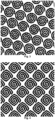
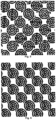
- the raster image of the present invention comprises spiral dots which are preferably regularly tiled, e.g. tiled along a triangular, rectangular or hexagonal grid (e.g. FIG. 3 and FIG. 13 ) and preferably tiled along a square grid (e.g. FIG. 1 and 11 ).
- the spiral dots may also be used in (semi)-random arranged halftone dots, such as blue noise or white noise arranged halftone dots.
- regularly tiled spiral dots are preferred in order to avoid irregular structures in the printed images.
- the distance between the centres of neighbouring dots may range from 50 ⁇ m to 400 ⁇ m.
- the raster image may further comprise conventional halftone dots, such as AM dots and/or FM dots, in combination with the spiral dots of the present invention (see e.g. FIG. 9 and 19 ).
- the raster image consists entirely of spiral dots according to the invention.
- the screen angle of the raster image according to the present invention is preferably selected from the group consisting of 0°+k ⁇ 30°, 7.5° + k ⁇ 30°, 15°+ k ⁇ 30°, 22.5°+k ⁇ 30° wherein k is a negative or positive integer.
- the most preferred embodiments have a screen angle selected from the group consisting of 0°, 15°, 75°, 90°, 45°, 67.5°, 22.5°,7.5°, 82.5° and 37.5°.
- the screen angles are measured as conventionally defined in the printing industry, i.e. counterclockwise from the horizontal axis to agree with the Cartesian coordinate system.
- the screen angle difference between the colour selections is preferably a multiplier of 15° or a multiplier of 30°.
- the spiral dots in the image of the present invention comprise only one "first arc” or one "first spiral", i.e. all the image pixels together form a single arc or a single spiral which may have a number of windings.
- first arc or one "first spiral”
- all the image pixels together form a single arc or a single spiral which may have a number of windings.
- raster images with halftone dots wherein the image pixels are arranged into more than one arc or more than one spiral are embodiments of the present invention.
- multiple arcs or spirals representing image pixels may be mutually connected at a common centre, as shown e.g. in FIGs.31-35 (3046-3049 and 30410).
- a spiral may be regarded as a combination of a plurality of arcs.
- An arc is a curved line which does not form a closed loop and typically corresponds to a segment of e.g. a circle or an ellipse, but also less conventional shapes are embraced by the term in the context of the present invention, e.g. segments of an optionally rounded rectangle or an optionally rounded triangle.
- the centre of the first arc or spiral may be a point (a single image or non-image pixel) but it can also be a clustered halftone dot similar to AM dots of the prior art.
- the central dot may have any shape, such as a circle or a square (see e.g. FIG. 29-35 : 3014-3019; 30110; 3026-3029; 30210; 3032-3039; 30310).
- the central dot may be larger in halftone dots which represent high image densities and smaller in halftone dots which represent low image densities.
- All the arcs which together constitute the first spiral are preferably mutually connected so that the first spiral represents a continuous line.
- the first spiral may also contain isolated non-image pixels or may comprise disconnected arcs, so that the first spiral is interrupted by empty space at one or more locations, as shown in FIG.39
- the empty space which separates adjacent arcs of the first spiral may be regarded as protrusions of the second spiral into the first spiral.
- protrusions of the second spiral may cut the first spiral completely into disconnected arcs, or incompletely whereby the first spiral is not interrupted but reduced locally to a lower thickness.
- the second spiral represents the non-image pixels of the raster image of our invention, i.e. the empty space between the arcs of the first spiral(s).
- the space between adjacent windings of the first spiral is completely empty, i.e. does not contain any image pixel.
- the empty space forms a continuous second spiral.
- the first spiral comprises protrusions of image pixels which extend into the empty space between the windings as shown in FIG. 28-35 (3063-3069 and 30610); such protrusions may connect two adjacent windings of the first spiral, thereby dividing the second spiral into two or more segments which are separated from one another by the mentioned protrusions of the first spiral.
- Other embodiments of the second arc or the second spiral may comprise isolated image pixels, i.e. image pixels which do not touch the first spiral, in the empty space between adjacent windings of the first spiral.
- the protrusions of the first arc or the first spiral may align so as to form one or more radial lines in the spiral dot ( FIG. 6 and FIG. 16 ) .
- the thickness of such a radial line may be e.g. from one pixel to five pixels.
- the thickness of said radial line(s) may be one or two pixels.
- the radial line may connect the centre of the spiral dot to the outer edge of the spiral dot, or may connect just two or more windings of the first spiral without making contact with the centre or the outer edge.
- the angle of a radial line may depend on the screen angle and/or start angle of the spiral.
- the second arc or second spiral is open-ended, i.e. not terminated by image pixels at the outer edge of the halftone dot, so that it forms an open channel that guides excess ink out of the dot in a controlled way.
- the higher ink accumulation may lead to uncontrolled ink splashes outside the outer edge of the dot, thereby producing irregularly shaped ink dots on the printed copies, resulting in a lower image quality.
- the thickness of the first and second arc and of the first and second spiral is independently from 1 to 10 pixels, more preferably from 2 to 5 pixels, which preferably corresponds to a thickness from 1 ⁇ m to 75 ⁇ m.
- the selection of the minimum thickness of the arc and spiral may be based on the resolution of the printing technique for which the raster image is intended.
- the maximum thickness which enables the controlled ink spreading referred to above, may be determined by the specific type of substrate on which the halftone raster image shall be printed and/or may be determined by the desired screen frequency. These and other selections, such as start angle, are preferably made in an input field of a user interface of a halftone generator.
- the thickness of the first arc or first spiral may also vary within the same dot, e.g. smaller at the centre than at the edge of the dot, see e.g. FIG.32 (3027) and 33 (3028). Such a spiral dot may produce less graininess, especially in the mid-tones of the image.
- FIGs.1-10 represent spiral dots with clockwise windings. Examples of counterclockwise windings are shown in e.g. FIG. 29-35 (3004-3010; 3014-19; 30110; 3024-29; 30210; 3034-3039; 30310).
- the start angle of the first arc or first spiral, at the centre of the dot is preferably the same for all spiral dots in the image.
- the start angle of each spiral dot is chosen randomly by a random number generator ( FIG 5 . and FIG. 15 ). This is a less preferred embodiment because the dots may touch each other in an irregular way which may result in noisiness.
- the shape of the first arc or first spiral may be of any type and different types of arcs and spirals can be combined within the same raster image (see e.g. the spiral dots of FIG.4 having a square shape with rounded edges, while the spiral dots of FIG.4 have a square shape without rounded edges).
- FIG. 1 , 3 and 8 represent Archimedean spirals with different parameters a and b.
- the first spiral may also be a circle involute, part of an Euler spiral, part of a logarithmic spiral, or a Fermat's spiral.
- the first spiral may also be an elliptical spiral ( FIG. 2 and 12 ).
- the major axis of the ellipse is preferably oriented along the screen angle or perpendicular to the screen angle of the raster image.
- the ink channel which is defined by the second arc or second spiral allows controlled spreading of the ink that is printed at areas defined by the first arc or first spiral, thereby enabling to obtain a higher image quality with less ink than in the state of the art.
- the controlled spreading of the ink also allows to reduce print mottle.
- print mottle is reduced by modification of the surface of the substrate, e.g. by applying an ink absorbing coating or by corona treatment or flame treatment before printing.
- the present invention allows to avoid such modification for some substrates.
- it also provides a better water absorption of the paper so that water interference mottle is reduced. It may even reduce shine-through, also called print-through, in absorbent substrates, whereby images become visible at the backside of the substrate.
- the present invention also allows to reduce moiré, which is known in the prior art to occur when different colours, screen frequencies and screen angles are printed on top of each other as disclosed in " The Theory of the Moiré Phenomenon" of Isaac Amidror; Kluwer Academic Publishers, (2000; ISBN 0-7923-5950-X), see Chapter 3 "Moiré minimization".
- moiré is known in the prior art to occur when different colours, screen frequencies and screen angles are printed on top of each other as disclosed in " The Theory of the Moiré Phenomenon" of Isaac Amidror; Kluwer Academic Publishers, (2000; ISBN 0-7923-5950-X), see Chapter 3 "Moiré minimization”.
- the second spiral in the halftone dots printed by one colour station can also act as an ink channel for the ink which has already been printed by another colour station.
- the spreading of the ink laid down on the substrate by the first colour station can be controlled in a better way than with conventional techniques such as AM halftoning, resulting in less moiré.
- spiral dots comprising multiple windings of a thin first spiral rather than dots which produce the same coverage with less but thicker windings. Multiple windings render the moiré effect less visible because such dots give the impression of a higher screen frequency.
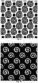
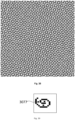
- the moiré effect produced by conventional screens results in typical rosette structures as shown in FIG.37 , which are less pronounced when using a raster image according to the invention ( FIG.38 ).
- the present invention is also less subject to a tone jump at the mid-tones, which may occur in conventional AM screens.
- the sudden tone jump also called density jump, which is known in the prior art, can be reduced because the accumulation of ink induced by the touching dots is drained by the ink channels in the dots.
- the spreading of the ink further enables faster drying of the printed copies.
- This allows to align press work with a proof, since they are both dry one doesn't have to account for dryback.
- Faster drying also reduces the risk of ink setoff, i.e. the transfer of ink from one printed copy to the back side of another copy lying on top of it, for example in the press delivery tray.
- the invention is therefore also very well suited for use with a perfecting press, which allows the simultaneous printing on both sides of a substrate in one pass through the press.
- Faster drying is also beneficial for printing on uncoated foils or plastics, and in newspaper printing. Faster printing speeds can be achieved and printed jobs can be brought faster to a bindery.
- offset printing with heatset ink the temperature of the drying ovens can be lowered, thereby saving energy costs.
- offset printing with curable ink becomes possible with less energy consumption by the curing unit, (UV LEDs, UV bulb or electron beam).
- the faster drying enabled by the present invention may also provide better trapping so that ink trap mottle is reduced.
- Inkjet printing also benefits from advantages of the present invention. Especially when the surface tension of the substrate causes dewetting, the raster image of the present invention gives a better print quality, such as uniform solid patches, compared to conventional AM screens, because the ink channel prevents local accumulation of ink on the substrate.
- the present invention enables inkjet printing at a high screen frequency, e.g. above 200 LPI (78.7 lines/cm), on a variety of substrates such as coated (plastic) film, translucent (plastic) film and newsprint, which was not achievable by state-of-the-art AM halftoning methods.
- the better uniformity of patches, produced by the raster image of the present invention makes it is easier to measure colour profiles for colour management systems and easier to match colour images, e.g. with online colour monitoring by measuring the printed copies during the press run. As a result, a print job comes faster in colour and less substrate is wasted.
- the raster image of the present invention is preferably generated by one or more threshold tiles, sometimes called threshold arrays, which transform a continuous-tone image to a halftone raster. Said transformation is also called threshold rendering.
- threshold tiles are well known in the art. More information about threshold tiles is disclosed in e.g. " Digital Color Halftoning” by Henry R. Kang, chapter 13; published in the SPIE/IEEE Series on Imaging Science and Engineering (11 November 1999; ISBN 0-8194-3318-7 ); and in “ Digital halftoning” by Robert Ulichney, chapter 5 and 6 (publisher MIT Press Cambridge, MA, USA; 1987; ISBN 0-262-21009-6 ).
- a conventional way of generating threshold tiles for AM screens is disclosed in the following patent applications: US5155599 , US5903713 and EP0910206 .
- Neighbouring spiral dots may grow in a different way, similar to conventional screens as disclosed in " Recent trends in digital halftoning", Proc. SPIE 2949, Imaging Sciences and Display Technologies, (1997); doi: 10.1117/12.266335 .
- the dot centres of the spiral dots may also be shifted as disclosed in US 6,128,099 .
- one threshold tile When used for binary digital halftoning, one threshold tile is sufficient to generate the raster image of the present invention.
- the number of threshold tiles is preferably the same as the number of colour channels in the continuous-tone image.
- the threshold tile comprises multiple equally sized arrays, one for each level.
- the shape of such arrays comprising threshold values can be a square or a rectangle but also Utah-shaped arrays or diamond-shaped arrays are suitable. More information about multilevel halftoning can be found in e.g. US5903713 .
- the transformation of a continuous-tone image to the halftone image of the present invention by means of one or more threshold tiles is similar to the prior art: the halftone dot coverage, which is typically expressed as a percentage and is defined by the number of image pixels in the dot, increases, as defined by the threshold tile, proportional to the corresponding density of the original continuous-tone image.
- the dot coverage of the spiral dots of the present invention can be increased in various ways : by growing the length of the first arc or first spiral and thereby increasing the dot size, as governed by consecutive values of the threshold tile (see FIGs.20 and 21 ); by increasing the thickness of the first arc or first spiral without increasing the dot size (thereby shrinking the empty space of the second spiral), either locally e.g. by adding protrusions to the first spiral, by increasing the thickness of one or more segments of the first spiral, and/or by increasing the thickness of the complete first spiral; by inserting image pixels inside the second spiral; or by a combination of any of these methods.
- FIG.22-24 show seven examples of threshold tiles having a dimension of 15x15 and comprising 10 consecutive threshold values numbered from 1 to 10. These threshold tiles are suitable for generating spiral dots according to the present invention, as shown in the FIGs. 26 to 35 .
- the dot coverage may be too low for the image pixels to represent a complete winding of the first spiral.
- the image pixels then represent a segment of the first spiral, i.e. a first arc as shown in FIGs. 26-28 .
- the transition from highlights to midtones is preferably made by increasing the thickness of said first arc and/or by growing the length of said first arc until a complete winding of the first spiral is formed.
- Still higher coverage can be obtained by increasing the thickness and/or the length of said first spiral which then may consist of more than one winding, including partial windings.
- the first spiral can no longer grow in length without overlapping with a neighbouring dot.
- darker images can be produced by shrinking the length and/or thickness of the second spiral, or by inserting image pixels inside the second spiral.
- the second spiral shrinks further and becomes an arc (the second arc).
- spiral dots with a high dot coverage no longer have an open-ended second spiral. Nevertheless, the advantages of the invention are still provided by such spiral dots, because the closed second spiral still defines a channel that can accept ink, so that a better print quality is produced with more uniform patches versus the state-of-the-art AM threshold tiles.
- the known advantages of state-of-the-art AM threshold tiles versus FM threshold tiles are also provided by the present invention, namely smoothness of flat-tones and rendering of mid-tones and better printing stability.
- the present invention also provides the advantages of state-of-the-art FM threshold tiles versus AM threshold tiles, namely rendering of fine details and closing in the shadows. Also no irregular "worms", or spaghetti-like structures are generated by the present invention as in 2 nd order FM threshold tiles which make the printed images more grainy, especially in vignettes and mid-tones.
- a set of threshold tiles is used to generate the a cross-modulated (XM) raster image according to the present invention, comprising small spiral dots of which the frequency is modulated in the highlight and shadow areas of the image, and larger spiral dots of which the amplitude is modulated in the mid-tones.
- XM cross-modulated
- screen frequencies above 200 LPI 78.7 lines/cm
- the ratio between resolution and screen frequency of the halftone raster image is preferably below 12, more preferably below 10.
- the screen frequency is preferably above 240 LPI (94.5 lines/cm).
- the one or more threshold tiles may be generated by a threshold tile generator, also called a halftone generator, which is comprised in a raster image processor or in a prepress workflow system, in accordance with options selected by the user via an input field of a user interface.
- Conventional options comprise image resolution, screen frequency, screen angle and screen shape.
- the number of options is preferably expanded by an input field for selecting the maximum thickness of the first and the second arc or spiral.
- An extra input field may be added for selecting the shape of the spiral dot (e.g. circular, elliptical, etc., as described above) and preferably also a parameter which further defines the selected shape such as ellipticity.
- Another input field may be added for the selection of one or more radial lines through the centre of the spiral dots and optionally also an additional input field for the specification of the thickness of the radial lines.
- the generator generates the threshold tile from these above-mentioned input fields, preferably by means of a screen function that defines a spiral-shape, such as the Archimedean spiral described above.
- the spiral shape or radial lines are preferably generated by calculation in polar coordinates contrary to state-of-the-art halftone generators wherein Cartesian coordinates are used.
- the halftone raster image of the present invention can be used in various printing techniques, most preferably lithographic printing, flexographic printing and digital printing.
- the raster image can be exposed on a light- or heat-sensitive material such as a lithographic or flexographic printing plate precursor by means of a laser, preferably a violet or an infrared laser.
- a printing plate carrying the raster image of the present invention is obtained. That plate can then be mounted on a printing press wherein ink is supplied to the plate which is then transferred onto the substrate to be printed.
- the raster image of the present invention is represented on the flexographic plate by spiral dots in relief.
- these halftone dots can be impressed more easily onto the substrate so that a better transfer of ink from the flexographic printing plate to the substrate can be achieved, especially by means of the open-ended ink channel.
- the raster image of the present invention is applied onto the substrate without a plate, e.g. by jetting ink with an inkjet printer.
- Preferred inkjet inks to be used in the context of this invention are UV-curable inks, (eco-)solvent inks and aqueous inks. All these techniques are well known in the art.
- Preferred inkjet printing techniques include wet-on-dry printing and wet-on-wet printing, either by jetting directly on a substrate or by jetting on and transferring from a transfer belt or drum onto a substrate.
- the predefined ink channel formed by the second spiral provides the mentioned advantages especially when jetting on non-absorbing substrates such as PET, polyethylene or the label substrates which are typically used in flexography.
- Our invention also allows to use high frequency screening in single pass inkjet systems.
- Alternative printing techniques which may benefit from the present invention are screen printing, serigraphy, gravure printing, etching, pad printing, or transfer printing; and digital printing techniques such as xerography, electrophotography, iconography, magnetography, laser printing, dye-sublimation printing, dot-matrix printing, thermal printing, nanography, or thermal (wax) transfer.
- the substrate on which the raster image may be printed can be of any kind, e.g. plastic films or foils, release liner, textiles, metal, glass, leather, hide, cotton and of course a variety of paper substrates (lightweight, heavyweight, coated, uncoated, paperboard, cardboard, etc.).
- the substrate may be a rigid work piece or a flexible sheet, roll or sleeve.
- Preferred flexible materials include e.g. paper, transparency foils, adhesive PVC sheets, etc., which may have a thickness less than 100 micrometres and preferably less than 50 micrometres.
- Preferred rigid substrates include e.g.
- the substrate may also be a flexible web material (e.g. paper, adhesive vinyl, fabrics, PVC, textile).
- a receiving layer for example an ink-receiving layer, may be applied on the substrate for a good adhesion of the reproduced image on the substrate.
- the present invention can also be used in 3D halftoning, such as stereolithography, digital light processing, fused deposition modelling, selective laser sintering, selective laser melting, electronic beam melting and laminated object manufacturing
- EX1, EX2, EX3, EX4, EX5, EX6 are all printed by a heatset press from Lithoman in CMYK (cyan, magenta, yellow and black) with the following materials and equipment:
- ABS is a PostScript TM -based conventional, halftone screening system that lifts up the quality of prints. Both halftoning methods (HT1, HT2) are using one threshold tile per color so easily implementable in workflow system comprising Postscript (PS)-interpreters and Portable document Format (PDF)-interpreters.
- PS Postscript
- PDF Portable document Format
- the 6 print jobs from the examples are week-magazines; printed for retail and food market; comprising new prices of consumer products and temporary promotions on colored solid backgrounds on 48 or 80 A4 pages, with imposition and recto/verso printing in CMYK on both side of the substrate. They are printed once in several copies with HT1 and once in several copies with HT2 at the same maximum density and same density for each tone value for each ink for having a similar printing result per color (cyan, magenta, yellow and black) between the two halftoning methods.
- the ink coverage can be calculated in Apogee TM after the halftoning step with the tone curve.
- the difference in ink coverage per example (e.g. EX1 vs EX2) is caused by other temporary (weekly) promotions and/or different layouting.
- the difference in ink coverage in each example between the halftoning methods HT1 and HT2 is caused by the use of a different tone value curve, also called linearization curve, so the densities for each ink are equal on print between the two halftoning methods (HT1, HT2).
- the total weight of used ink versus number of copies between the HT1 printed copies and the HT2 printed copies is compared to calculate the ink saving when using HT2. These examples shows that using HT2 uses less ink. Lower ink in a copy provides better water/ink balance, resulting in higher speed and there is the possibility to lower the temperature in the heatset oven.
Landscapes
- Engineering & Computer Science (AREA)
- Manufacturing & Machinery (AREA)
- Multimedia (AREA)
- Signal Processing (AREA)
- General Engineering & Computer Science (AREA)
- Physics & Mathematics (AREA)
- General Physics & Mathematics (AREA)
- Theoretical Computer Science (AREA)
- Health & Medical Sciences (AREA)
- General Health & Medical Sciences (AREA)
- Toxicology (AREA)
- Facsimile Image Signal Circuits (AREA)
- Printing Methods (AREA)
- Ink Jet (AREA)
- Manufacture Or Reproduction Of Printing Formes (AREA)
- Particle Formation And Scattering Control In Inkjet Printers (AREA)
- Image Processing (AREA)
Applications Claiming Priority (4)
| Application Number | Priority Date | Filing Date | Title |
|---|---|---|---|
| EP17198925 | 2017-10-27 | ||
| EP18188424 | 2018-08-10 | ||
| EP18803866.5A EP3701710B1 (en) | 2017-10-27 | 2018-10-23 | Digital halftoning with spiral dots |
| PCT/EP2018/079011 WO2019081493A1 (en) | 2017-10-27 | 2018-10-23 | DIGITAL HALF TINT WITH SPIRAL POINTS |
Related Parent Applications (2)
| Application Number | Title | Priority Date | Filing Date |
|---|---|---|---|
| EP18803866.5A Division EP3701710B1 (en) | 2017-10-27 | 2018-10-23 | Digital halftoning with spiral dots |
| EP18803866.5A Division-Into EP3701710B1 (en) | 2017-10-27 | 2018-10-23 | Digital halftoning with spiral dots |
Publications (3)
| Publication Number | Publication Date |
|---|---|
| EP4075778A1 EP4075778A1 (en) | 2022-10-19 |
| EP4075778C0 EP4075778C0 (en) | 2024-08-28 |
| EP4075778B1 true EP4075778B1 (en) | 2024-08-28 |
Family
ID=64331998
Family Applications (2)
| Application Number | Title | Priority Date | Filing Date |
|---|---|---|---|
| EP22171731.7A Active EP4075778B1 (en) | 2017-10-27 | 2018-10-23 | Raster image processor |
| EP18803866.5A Active EP3701710B1 (en) | 2017-10-27 | 2018-10-23 | Digital halftoning with spiral dots |
Family Applications After (1)
| Application Number | Title | Priority Date | Filing Date |
|---|---|---|---|
| EP18803866.5A Active EP3701710B1 (en) | 2017-10-27 | 2018-10-23 | Digital halftoning with spiral dots |
Country Status (12)
| Country | Link |
|---|---|
| US (1) | US11667115B2 (pl) |
| EP (2) | EP4075778B1 (pl) |
| JP (1) | JP7121357B2 (pl) |
| KR (1) | KR102389276B1 (pl) |
| CN (1) | CN111434101B (pl) |
| AU (1) | AU2018356367B2 (pl) |
| BR (1) | BR112020008209A8 (pl) |
| DK (1) | DK3701710T3 (pl) |
| ES (2) | ES2935407T3 (pl) |
| PL (1) | PL3701710T3 (pl) |
| RU (1) | RU2749305C1 (pl) |
| WO (1) | WO2019081493A1 (pl) |
Families Citing this family (10)
| Publication number | Priority date | Publication date | Assignee | Title |
|---|---|---|---|---|
| PL3834406T3 (pl) | 2018-08-10 | 2024-04-08 | Eco3 Bv | Rastrowanie cyfrowe z punktami reprezentującymi spiralę |
| US20220230031A1 (en) | 2019-04-30 | 2022-07-21 | Agfa Nv | Raster image processor |
| PL3963874T3 (pl) | 2019-04-30 | 2025-09-22 | Eco3 Bv | Rastrowanie cyfrowe z punktami spiralnymi |
| NL2023203B1 (en) * | 2019-05-27 | 2020-12-02 | Spgprints B V | Screen printing, in particular rotary screen printing of textile materials |
| CN114026839A (zh) * | 2019-06-05 | 2022-02-08 | 爱克发胶印有限公司 | 数字半色调的方法 |
| CN112060793B (zh) * | 2020-07-31 | 2022-04-05 | 安徽美盈森智谷科技有限公司 | 一种瓦楞纸箱渐变色图案柔性印刷工艺 |
| DE102020128450B4 (de) | 2020-10-29 | 2025-09-04 | Koenig & Bauer Ag | Verfahren zum Betreiben einer Tintenstrahldruckmaschine |
| CN114343839B (zh) * | 2021-12-30 | 2024-07-23 | 德州环球之光医疗科技股份有限公司 | 一种基于可调的螺旋线型激光光斑的治疗图形转换方法 |
| PL4443860T3 (pl) | 2023-04-07 | 2025-10-27 | Eco3 Bv | Sposób wytwarzania płyty drukowej |
| US12373661B2 (en) | 2023-12-14 | 2025-07-29 | Ricoh Company, Ltd. | Vectorized interleave of bit planes |
Family Cites Families (35)
| Publication number | Priority date | Publication date | Assignee | Title |
|---|---|---|---|---|
| DE3228387A1 (de) * | 1981-07-30 | 1983-02-24 | GAO Gesellschaft für Automation und Organisation mbH, 8000 München | Verfahren zur aufrasterung von halbtonbildmotiven |
| US5155599A (en) | 1991-07-25 | 1992-10-13 | Miles, Inc. | Screening system and method for color reproduction in offset printing |
| EP0734147B1 (en) * | 1995-03-22 | 2000-06-14 | Agfa-Gevaert N.V. | Intensity modulated stochastic screening for preparing a lithographic printing plate |
| EP0740457B1 (en) * | 1995-04-28 | 1999-07-21 | Agfa-Gevaert N.V. | Printing plate and method for the reproduction of images |
| DE69518626T2 (de) | 1995-05-05 | 2001-05-03 | Agfa-Gevaert N.V., Mortsel | Moirefreie Multipegelhalbtonerzeugung für Farbbilder |
| US5706099A (en) * | 1995-06-05 | 1998-01-06 | Xerox Corporation | Method and apparatus for generating serpentine halftone images |
| US6128099A (en) | 1995-06-08 | 2000-10-03 | Delabastita; Paul A. | Halftone screen generator, halftone screen and method for generating same |
| US6081345A (en) * | 1998-01-29 | 2000-06-27 | Xerox Corporation | Line screen having extended dynamic tone range for embedding machine readable data in halftone images |
| US6092732A (en) * | 1998-01-29 | 2000-07-25 | Xerox Corporation | Selectively accented serpentine halftone patterns for embedding human readable information in images |
| US7016073B1 (en) * | 1999-07-27 | 2006-03-21 | Xerox Corporation | Digital halftone with auxiliary pixels |
| WO2003028362A1 (en) * | 2001-09-21 | 2003-04-03 | Ricoh Company, Ltd. | Threshold value matrix creating method, image output system, storage medium, gradation reproducing method, threshold value matrix, image processing method, image processing apparatus, image forming apparatus and printer driver |
| US7171901B2 (en) * | 2001-10-18 | 2007-02-06 | Kodak Graphic Communications Canada Company | Flexographic printing method |
| US20030107768A1 (en) * | 2001-12-04 | 2003-06-12 | Crounse Kenneth R. | Halftoning with uniformly dispersed dot growth |
| EP1428666B1 (en) | 2002-12-11 | 2007-04-25 | Agfa Graphics N.V. | Preparation of flexographic printing plates using ink jet recording |
| US6881533B2 (en) * | 2003-02-18 | 2005-04-19 | Kodak Polychrome Graphics Llc | Flexographic printing plate with ink-repellent non-image areas |
| US7126724B2 (en) * | 2003-03-11 | 2006-10-24 | Kodak Graphic Communications Canada Company | Flexographic printing |
| JP2005026987A (ja) | 2003-07-01 | 2005-01-27 | Dainippon Printing Co Ltd | 印刷網点、印刷版および網点形成方法 |
| DE60320549T2 (de) | 2003-08-13 | 2009-05-14 | Agfa Graphics N.V. | Verfahren zum Nacheinbrennen von lithographischen Druckplatten |
| JP2005136612A (ja) * | 2003-10-29 | 2005-05-26 | Dainippon Screen Mfg Co Ltd | 網点形成方法、網点形成装置および網点記録媒体 |
| US20050157347A1 (en) | 2004-01-21 | 2005-07-21 | Hans Dewitte | Relief plates, platemaking masters therefor, and methods for producing such plate making masters and plates |
| EP1742801A1 (en) | 2004-05-05 | 2007-01-17 | Glunz & Jensen A/S | System and method for inkjet printing |
| EP1766959A1 (en) * | 2004-05-05 | 2007-03-28 | Eastman Kodak Company | Color management of halftone prints |
| US7557962B2 (en) * | 2004-07-13 | 2009-07-07 | Toshiba Corporation | System and method for tone-dependent multi-frequency halftone screening |
| JP4640647B2 (ja) | 2005-02-22 | 2011-03-02 | 富士ゼロックス株式会社 | 画像処理方法および画像処理装置並びに画像形成装置 |
| US8132508B2 (en) * | 2005-04-14 | 2012-03-13 | Esko Software Bvba | Method of controlling ink film thickness on a printing plate |
| RU2344045C1 (ru) * | 2007-08-03 | 2009-01-20 | Федеральное Государственное Унитарное Предприятие "Гознак" (Фгуп "Гознак") | Защитный элемент для защиты от подделки, защищенная полиграфическая продукция и способ изготовления защищенной полиграфической продукции |
| US8400681B1 (en) * | 2009-06-10 | 2013-03-19 | Girard J. Moravcik | Enhanced halftone screening method for the dry offset printing process |
| US20120048133A1 (en) * | 2010-08-25 | 2012-03-01 | Burberry Mitchell S | Flexographic printing members |
| CN103269854B (zh) * | 2010-12-23 | 2015-04-22 | 利乐拉瓦尔集团及财务有限公司 | 改进的苯胺印刷、装置以及方法 |
| US8693061B2 (en) * | 2011-07-19 | 2014-04-08 | Eastman Kodak Company | Method of embedding data in printed halftone features on a receiver |
| JP5141995B1 (ja) | 2012-02-01 | 2013-02-13 | 富士ゼロックス株式会社 | 印刷制御装置、画像形成システムおよびプログラム |
| NL2016019B1 (en) * | 2015-12-23 | 2017-07-03 | Xeikon Prepress Nv | Improved flexography printing. |
| US9819828B2 (en) * | 2016-03-15 | 2017-11-14 | Xerox Corporation | Non-printing dot halftone patterns |
| EP3243668B1 (en) * | 2016-05-10 | 2020-07-15 | Agfa Nv | Manufacturing of a security document |
| US10027847B2 (en) * | 2016-09-22 | 2018-07-17 | Kyocera Document Solutions Inc. | Selection of halftoning technique |
-
2018
- 2018-10-23 PL PL18803866.5T patent/PL3701710T3/pl unknown
- 2018-10-23 EP EP22171731.7A patent/EP4075778B1/en active Active
- 2018-10-23 CN CN201880070046.7A patent/CN111434101B/zh active Active
- 2018-10-23 JP JP2020523745A patent/JP7121357B2/ja active Active
- 2018-10-23 ES ES18803866T patent/ES2935407T3/es active Active
- 2018-10-23 WO PCT/EP2018/079011 patent/WO2019081493A1/en not_active Ceased
- 2018-10-23 BR BR112020008209A patent/BR112020008209A8/pt unknown
- 2018-10-23 EP EP18803866.5A patent/EP3701710B1/en active Active
- 2018-10-23 DK DK18803866.5T patent/DK3701710T3/da active
- 2018-10-23 KR KR1020207012016A patent/KR102389276B1/ko active Active
- 2018-10-23 US US16/758,876 patent/US11667115B2/en active Active
- 2018-10-23 RU RU2020117294A patent/RU2749305C1/ru active
- 2018-10-23 ES ES22171731T patent/ES2987359T3/es active Active
- 2018-10-23 AU AU2018356367A patent/AU2018356367B2/en active Active
Also Published As
| Publication number | Publication date |
|---|---|
| JP7121357B2 (ja) | 2022-08-18 |
| RU2749305C1 (ru) | 2021-06-08 |
| DK3701710T3 (da) | 2023-02-13 |
| JP2021500824A (ja) | 2021-01-07 |
| CN111434101A (zh) | 2020-07-17 |
| WO2019081493A1 (en) | 2019-05-02 |
| US11667115B2 (en) | 2023-06-06 |
| CA3080250A1 (en) | 2019-05-02 |
| AU2018356367A1 (en) | 2020-06-11 |
| BR112020008209A8 (pt) | 2022-08-02 |
| KR20200058500A (ko) | 2020-05-27 |
| PL3701710T3 (pl) | 2023-05-08 |
| EP4075778A1 (en) | 2022-10-19 |
| ES2987359T3 (es) | 2024-11-14 |
| AU2018356367B2 (en) | 2021-04-01 |
| US20210370661A1 (en) | 2021-12-02 |
| EP4075778C0 (en) | 2024-08-28 |
| BR112020008209A2 (pt) | 2020-10-27 |
| EP3701710B1 (en) | 2022-12-28 |
| KR102389276B1 (ko) | 2022-04-21 |
| CN111434101B (zh) | 2022-09-09 |
| EP3701710A1 (en) | 2020-09-02 |
| ES2935407T3 (es) | 2023-03-06 |
Similar Documents
| Publication | Publication Date | Title |
|---|---|---|
| EP3701710B1 (en) | Digital halftoning with spiral dots | |
| EP3963874B1 (en) | Digital halftoning with spiral dots | |
| EP3981139B1 (en) | A method of digital halftoning | |
| EP3834406B1 (en) | Digital halftoning with dots representing a spiral | |
| EP3963875B1 (en) | Raster image processor | |
| CA3080250C (en) | Digital halftoning with spiral dots |
Legal Events
| Date | Code | Title | Description |
|---|---|---|---|
| PUAI | Public reference made under article 153(3) epc to a published international application that has entered the european phase |
Free format text: ORIGINAL CODE: 0009012 |
|
| STAA | Information on the status of an ep patent application or granted ep patent |
Free format text: STATUS: THE APPLICATION HAS BEEN PUBLISHED |
|
| AC | Divisional application: reference to earlier application |
Ref document number: 3701710 Country of ref document: EP Kind code of ref document: P |
|
| AK | Designated contracting states |
Kind code of ref document: A1 Designated state(s): AL AT BE BG CH CY CZ DE DK EE ES FI FR GB GR HR HU IE IS IT LI LT LU LV MC MK MT NL NO PL PT RO RS SE SI SK SM TR |
|
| STAA | Information on the status of an ep patent application or granted ep patent |
Free format text: STATUS: REQUEST FOR EXAMINATION WAS MADE |
|
| 17P | Request for examination filed |
Effective date: 20230419 |
|
| RBV | Designated contracting states (corrected) |
Designated state(s): AL AT BE BG CH CY CZ DE DK EE ES FI FR GB GR HR HU IE IS IT LI LT LU LV MC MK MT NL NO PL PT RO RS SE SI SK SM TR |
|
| RAP3 | Party data changed (applicant data changed or rights of an application transferred) |
Owner name: ECO3 BV |
|
| RIC1 | Information provided on ipc code assigned before grant |
Ipc: B41N 1/22 20060101ALN20240328BHEP Ipc: B41N 1/12 20060101ALN20240328BHEP Ipc: B41M 3/00 20060101ALN20240328BHEP Ipc: B41M 1/06 20060101ALN20240328BHEP Ipc: B41M 1/04 20060101ALN20240328BHEP Ipc: B41C 1/10 20060101ALN20240328BHEP Ipc: B41C 1/02 20060101ALN20240328BHEP Ipc: B41J 2/205 20060101ALI20240328BHEP Ipc: H04N 1/405 20060101AFI20240328BHEP |
|
| GRAP | Despatch of communication of intention to grant a patent |
Free format text: ORIGINAL CODE: EPIDOSNIGR1 |
|
| STAA | Information on the status of an ep patent application or granted ep patent |
Free format text: STATUS: GRANT OF PATENT IS INTENDED |
|
| INTG | Intention to grant announced |
Effective date: 20240503 |
|
| RIC1 | Information provided on ipc code assigned before grant |
Ipc: B41N 1/22 20060101ALN20240422BHEP Ipc: B41N 1/12 20060101ALN20240422BHEP Ipc: B41M 3/00 20060101ALN20240422BHEP Ipc: B41M 1/06 20060101ALN20240422BHEP Ipc: B41M 1/04 20060101ALN20240422BHEP Ipc: B41C 1/10 20060101ALN20240422BHEP Ipc: B41C 1/02 20060101ALN20240422BHEP Ipc: B41J 2/205 20060101ALI20240422BHEP Ipc: H04N 1/405 20060101AFI20240422BHEP |
|
| GRAS | Grant fee paid |
Free format text: ORIGINAL CODE: EPIDOSNIGR3 |
|
| GRAA | (expected) grant |
Free format text: ORIGINAL CODE: 0009210 |
|
| STAA | Information on the status of an ep patent application or granted ep patent |
Free format text: STATUS: THE PATENT HAS BEEN GRANTED |
|
| AC | Divisional application: reference to earlier application |
Ref document number: 3701710 Country of ref document: EP Kind code of ref document: P |
|
| AK | Designated contracting states |
Kind code of ref document: B1 Designated state(s): AL AT BE BG CH CY CZ DE DK EE ES FI FR GB GR HR HU IE IS IT LI LT LU LV MC MK MT NL NO PL PT RO RS SE SI SK SM TR |
|
| REG | Reference to a national code |
Ref country code: CH Ref legal event code: EP |
|
| REG | Reference to a national code |
Ref country code: DE Ref legal event code: R096 Ref document number: 602018073854 Country of ref document: DE |
|
| REG | Reference to a national code |
Ref country code: IE Ref legal event code: FG4D |
|
| U01 | Request for unitary effect filed |
Effective date: 20240906 |
|
| U07 | Unitary effect registered |
Designated state(s): AT BE BG DE DK EE FI FR IT LT LU LV MT NL PT RO SE SI Effective date: 20240924 |
|
| REG | Reference to a national code |
Ref country code: ES Ref legal event code: FG2A Ref document number: 2987359 Country of ref document: ES Kind code of ref document: T3 Effective date: 20241114 |
|
| U20 | Renewal fee for the european patent with unitary effect paid |
Year of fee payment: 7 Effective date: 20241025 |
|
| PG25 | Lapsed in a contracting state [announced via postgrant information from national office to epo] |
Ref country code: NO Free format text: LAPSE BECAUSE OF FAILURE TO SUBMIT A TRANSLATION OF THE DESCRIPTION OR TO PAY THE FEE WITHIN THE PRESCRIBED TIME-LIMIT Effective date: 20241128 |
|
| PG25 | Lapsed in a contracting state [announced via postgrant information from national office to epo] |
Ref country code: PL Free format text: LAPSE BECAUSE OF FAILURE TO SUBMIT A TRANSLATION OF THE DESCRIPTION OR TO PAY THE FEE WITHIN THE PRESCRIBED TIME-LIMIT Effective date: 20240828 Ref country code: GR Free format text: LAPSE BECAUSE OF FAILURE TO SUBMIT A TRANSLATION OF THE DESCRIPTION OR TO PAY THE FEE WITHIN THE PRESCRIBED TIME-LIMIT Effective date: 20241129 |
|
| PG25 | Lapsed in a contracting state [announced via postgrant information from national office to epo] |
Ref country code: IS Free format text: LAPSE BECAUSE OF FAILURE TO SUBMIT A TRANSLATION OF THE DESCRIPTION OR TO PAY THE FEE WITHIN THE PRESCRIBED TIME-LIMIT Effective date: 20241228 |
|
| PG25 | Lapsed in a contracting state [announced via postgrant information from national office to epo] |
Ref country code: HR Free format text: LAPSE BECAUSE OF FAILURE TO SUBMIT A TRANSLATION OF THE DESCRIPTION OR TO PAY THE FEE WITHIN THE PRESCRIBED TIME-LIMIT Effective date: 20240828 |
|
| PG25 | Lapsed in a contracting state [announced via postgrant information from national office to epo] |
Ref country code: RS Free format text: LAPSE BECAUSE OF FAILURE TO SUBMIT A TRANSLATION OF THE DESCRIPTION OR TO PAY THE FEE WITHIN THE PRESCRIBED TIME-LIMIT Effective date: 20241128 |
|
| PG25 | Lapsed in a contracting state [announced via postgrant information from national office to epo] |
Ref country code: RS Free format text: LAPSE BECAUSE OF FAILURE TO SUBMIT A TRANSLATION OF THE DESCRIPTION OR TO PAY THE FEE WITHIN THE PRESCRIBED TIME-LIMIT Effective date: 20241128 Ref country code: PL Free format text: LAPSE BECAUSE OF FAILURE TO SUBMIT A TRANSLATION OF THE DESCRIPTION OR TO PAY THE FEE WITHIN THE PRESCRIBED TIME-LIMIT Effective date: 20240828 Ref country code: NO Free format text: LAPSE BECAUSE OF FAILURE TO SUBMIT A TRANSLATION OF THE DESCRIPTION OR TO PAY THE FEE WITHIN THE PRESCRIBED TIME-LIMIT Effective date: 20241128 Ref country code: IS Free format text: LAPSE BECAUSE OF FAILURE TO SUBMIT A TRANSLATION OF THE DESCRIPTION OR TO PAY THE FEE WITHIN THE PRESCRIBED TIME-LIMIT Effective date: 20241228 Ref country code: HR Free format text: LAPSE BECAUSE OF FAILURE TO SUBMIT A TRANSLATION OF THE DESCRIPTION OR TO PAY THE FEE WITHIN THE PRESCRIBED TIME-LIMIT Effective date: 20240828 Ref country code: GR Free format text: LAPSE BECAUSE OF FAILURE TO SUBMIT A TRANSLATION OF THE DESCRIPTION OR TO PAY THE FEE WITHIN THE PRESCRIBED TIME-LIMIT Effective date: 20241129 |
|
| PG25 | Lapsed in a contracting state [announced via postgrant information from national office to epo] |
Ref country code: SM Free format text: LAPSE BECAUSE OF FAILURE TO SUBMIT A TRANSLATION OF THE DESCRIPTION OR TO PAY THE FEE WITHIN THE PRESCRIBED TIME-LIMIT Effective date: 20240828 |
|
| PG25 | Lapsed in a contracting state [announced via postgrant information from national office to epo] |
Ref country code: CZ Free format text: LAPSE BECAUSE OF FAILURE TO SUBMIT A TRANSLATION OF THE DESCRIPTION OR TO PAY THE FEE WITHIN THE PRESCRIBED TIME-LIMIT Effective date: 20240828 |
|
| PG25 | Lapsed in a contracting state [announced via postgrant information from national office to epo] |
Ref country code: SK Free format text: LAPSE BECAUSE OF FAILURE TO SUBMIT A TRANSLATION OF THE DESCRIPTION OR TO PAY THE FEE WITHIN THE PRESCRIBED TIME-LIMIT Effective date: 20240828 |
|
| REG | Reference to a national code |
Ref country code: CH Ref legal event code: PL |
|
| PLBE | No opposition filed within time limit |
Free format text: ORIGINAL CODE: 0009261 |
|
| STAA | Information on the status of an ep patent application or granted ep patent |
Free format text: STATUS: NO OPPOSITION FILED WITHIN TIME LIMIT |
|
| PG25 | Lapsed in a contracting state [announced via postgrant information from national office to epo] |
Ref country code: MC Free format text: LAPSE BECAUSE OF FAILURE TO SUBMIT A TRANSLATION OF THE DESCRIPTION OR TO PAY THE FEE WITHIN THE PRESCRIBED TIME-LIMIT Effective date: 20240828 |
|
| PG25 | Lapsed in a contracting state [announced via postgrant information from national office to epo] |
Ref country code: CH Free format text: LAPSE BECAUSE OF NON-PAYMENT OF DUE FEES Effective date: 20241031 |
|
| 26N | No opposition filed |
Effective date: 20250530 |
|
| PG25 | Lapsed in a contracting state [announced via postgrant information from national office to epo] |
Ref country code: IE Free format text: LAPSE BECAUSE OF NON-PAYMENT OF DUE FEES Effective date: 20241023 |
|
| U20 | Renewal fee for the european patent with unitary effect paid |
Year of fee payment: 8 Effective date: 20251028 |
|
| PGFP | Annual fee paid to national office [announced via postgrant information from national office to epo] |
Ref country code: GB Payment date: 20251022 Year of fee payment: 8 |
|
| PG25 | Lapsed in a contracting state [announced via postgrant information from national office to epo] |
Ref country code: CY Free format text: LAPSE BECAUSE OF FAILURE TO SUBMIT A TRANSLATION OF THE DESCRIPTION OR TO PAY THE FEE WITHIN THE PRESCRIBED TIME-LIMIT; INVALID AB INITIO Effective date: 20181023 |
|
| PGFP | Annual fee paid to national office [announced via postgrant information from national office to epo] |
Ref country code: ES Payment date: 20251216 Year of fee payment: 8 |
|
| PG25 | Lapsed in a contracting state [announced via postgrant information from national office to epo] |
Ref country code: HU Free format text: LAPSE BECAUSE OF FAILURE TO SUBMIT A TRANSLATION OF THE DESCRIPTION OR TO PAY THE FEE WITHIN THE PRESCRIBED TIME-LIMIT; INVALID AB INITIO Effective date: 20181023 |