EP4075589A1 - Battery, electric device, and battery manufacturing method and device - Google Patents
Battery, electric device, and battery manufacturing method and device Download PDFInfo
- Publication number
- EP4075589A1 EP4075589A1 EP20957981.2A EP20957981A EP4075589A1 EP 4075589 A1 EP4075589 A1 EP 4075589A1 EP 20957981 A EP20957981 A EP 20957981A EP 4075589 A1 EP4075589 A1 EP 4075589A1
- Authority
- EP
- European Patent Office
- Prior art keywords
- battery
- pressure relief
- battery cell
- region
- relief mechanism
- Prior art date
- Legal status (The legal status is an assumption and is not a legal conclusion. Google has not performed a legal analysis and makes no representation as to the accuracy of the status listed.)
- Granted
Links
Images




Classifications
-
- H—ELECTRICITY
- H01—ELECTRIC ELEMENTS
- H01M—PROCESSES OR MEANS, e.g. BATTERIES, FOR THE DIRECT CONVERSION OF CHEMICAL ENERGY INTO ELECTRICAL ENERGY
- H01M50/00—Constructional details or processes of manufacture of the non-active parts of electrochemical cells other than fuel cells, e.g. hybrid cells
- H01M50/30—Arrangements for facilitating escape of gases
- H01M50/342—Non-re-sealable arrangements
- H01M50/3425—Non-re-sealable arrangements in the form of rupturable membranes or weakened parts, e.g. pierced with the aid of a sharp member
-
- H—ELECTRICITY
- H01—ELECTRIC ELEMENTS
- H01M—PROCESSES OR MEANS, e.g. BATTERIES, FOR THE DIRECT CONVERSION OF CHEMICAL ENERGY INTO ELECTRICAL ENERGY
- H01M50/00—Constructional details or processes of manufacture of the non-active parts of electrochemical cells other than fuel cells, e.g. hybrid cells
- H01M50/50—Current conducting connections for cells or batteries
- H01M50/572—Means for preventing undesired use or discharge
- H01M50/584—Means for preventing undesired use or discharge for preventing incorrect connections inside or outside the batteries
- H01M50/59—Means for preventing undesired use or discharge for preventing incorrect connections inside or outside the batteries characterised by the protection means
- H01M50/593—Spacers; Insulating plates
-
- H—ELECTRICITY
- H01—ELECTRIC ELEMENTS
- H01M—PROCESSES OR MEANS, e.g. BATTERIES, FOR THE DIRECT CONVERSION OF CHEMICAL ENERGY INTO ELECTRICAL ENERGY
- H01M50/00—Constructional details or processes of manufacture of the non-active parts of electrochemical cells other than fuel cells, e.g. hybrid cells
- H01M50/20—Mountings; Secondary casings or frames; Racks, modules or packs; Suspension devices; Shock absorbers; Transport or carrying devices; Holders
- H01M50/204—Racks, modules or packs for multiple batteries or multiple cells
-
- H—ELECTRICITY
- H01—ELECTRIC ELEMENTS
- H01M—PROCESSES OR MEANS, e.g. BATTERIES, FOR THE DIRECT CONVERSION OF CHEMICAL ENERGY INTO ELECTRICAL ENERGY
- H01M50/00—Constructional details or processes of manufacture of the non-active parts of electrochemical cells other than fuel cells, e.g. hybrid cells
- H01M50/20—Mountings; Secondary casings or frames; Racks, modules or packs; Suspension devices; Shock absorbers; Transport or carrying devices; Holders
- H01M50/204—Racks, modules or packs for multiple batteries or multiple cells
- H01M50/207—Racks, modules or packs for multiple batteries or multiple cells characterised by their shape
- H01M50/209—Racks, modules or packs for multiple batteries or multiple cells characterised by their shape adapted for prismatic or rectangular cells
-
- H—ELECTRICITY
- H01—ELECTRIC ELEMENTS
- H01M—PROCESSES OR MEANS, e.g. BATTERIES, FOR THE DIRECT CONVERSION OF CHEMICAL ENERGY INTO ELECTRICAL ENERGY
- H01M50/00—Constructional details or processes of manufacture of the non-active parts of electrochemical cells other than fuel cells, e.g. hybrid cells
- H01M50/30—Arrangements for facilitating escape of gases
- H01M50/375—Vent means sensitive to or responsive to temperature
-
- H—ELECTRICITY
- H01—ELECTRIC ELEMENTS
- H01M—PROCESSES OR MEANS, e.g. BATTERIES, FOR THE DIRECT CONVERSION OF CHEMICAL ENERGY INTO ELECTRICAL ENERGY
- H01M50/00—Constructional details or processes of manufacture of the non-active parts of electrochemical cells other than fuel cells, e.g. hybrid cells
- H01M50/30—Arrangements for facilitating escape of gases
- H01M50/383—Flame arresting or ignition-preventing means
-
- H—ELECTRICITY
- H01—ELECTRIC ELEMENTS
- H01M—PROCESSES OR MEANS, e.g. BATTERIES, FOR THE DIRECT CONVERSION OF CHEMICAL ENERGY INTO ELECTRICAL ENERGY
- H01M50/00—Constructional details or processes of manufacture of the non-active parts of electrochemical cells other than fuel cells, e.g. hybrid cells
- H01M50/50—Current conducting connections for cells or batteries
- H01M50/502—Interconnectors for connecting terminals of adjacent batteries; Interconnectors for connecting cells outside a battery casing
- H01M50/507—Interconnectors for connecting terminals of adjacent batteries; Interconnectors for connecting cells outside a battery casing comprising an arrangement of two or more busbars within a container structure, e.g. busbar modules
-
- H—ELECTRICITY
- H01—ELECTRIC ELEMENTS
- H01M—PROCESSES OR MEANS, e.g. BATTERIES, FOR THE DIRECT CONVERSION OF CHEMICAL ENERGY INTO ELECTRICAL ENERGY
- H01M50/00—Constructional details or processes of manufacture of the non-active parts of electrochemical cells other than fuel cells, e.g. hybrid cells
- H01M50/50—Current conducting connections for cells or batteries
- H01M50/502—Interconnectors for connecting terminals of adjacent batteries; Interconnectors for connecting cells outside a battery casing
- H01M50/514—Methods for interconnecting adjacent batteries or cells
-
- H—ELECTRICITY
- H01—ELECTRIC ELEMENTS
- H01M—PROCESSES OR MEANS, e.g. BATTERIES, FOR THE DIRECT CONVERSION OF CHEMICAL ENERGY INTO ELECTRICAL ENERGY
- H01M50/00—Constructional details or processes of manufacture of the non-active parts of electrochemical cells other than fuel cells, e.g. hybrid cells
- H01M50/50—Current conducting connections for cells or batteries
- H01M50/572—Means for preventing undesired use or discharge
- H01M50/584—Means for preventing undesired use or discharge for preventing incorrect connections inside or outside the batteries
- H01M50/588—Means for preventing undesired use or discharge for preventing incorrect connections inside or outside the batteries outside the batteries, e.g. incorrect connections of terminals or busbars
-
- H—ELECTRICITY
- H01—ELECTRIC ELEMENTS
- H01M—PROCESSES OR MEANS, e.g. BATTERIES, FOR THE DIRECT CONVERSION OF CHEMICAL ENERGY INTO ELECTRICAL ENERGY
- H01M50/00—Constructional details or processes of manufacture of the non-active parts of electrochemical cells other than fuel cells, e.g. hybrid cells
- H01M50/50—Current conducting connections for cells or batteries
- H01M50/572—Means for preventing undesired use or discharge
- H01M50/584—Means for preventing undesired use or discharge for preventing incorrect connections inside or outside the batteries
- H01M50/59—Means for preventing undesired use or discharge for preventing incorrect connections inside or outside the batteries characterised by the protection means
-
- H—ELECTRICITY
- H01—ELECTRIC ELEMENTS
- H01M—PROCESSES OR MEANS, e.g. BATTERIES, FOR THE DIRECT CONVERSION OF CHEMICAL ENERGY INTO ELECTRICAL ENERGY
- H01M2200/00—Safety devices for primary or secondary batteries
- H01M2200/10—Temperature sensitive devices
-
- H—ELECTRICITY
- H01—ELECTRIC ELEMENTS
- H01M—PROCESSES OR MEANS, e.g. BATTERIES, FOR THE DIRECT CONVERSION OF CHEMICAL ENERGY INTO ELECTRICAL ENERGY
- H01M2200/00—Safety devices for primary or secondary batteries
- H01M2200/20—Pressure-sensitive devices
-
- H—ELECTRICITY
- H01—ELECTRIC ELEMENTS
- H01M—PROCESSES OR MEANS, e.g. BATTERIES, FOR THE DIRECT CONVERSION OF CHEMICAL ENERGY INTO ELECTRICAL ENERGY
- H01M2250/00—Fuel cells for particular applications; Specific features of fuel cell system
- H01M2250/20—Fuel cells in motive systems, e.g. vehicle, ship, plane
-
- Y—GENERAL TAGGING OF NEW TECHNOLOGICAL DEVELOPMENTS; GENERAL TAGGING OF CROSS-SECTIONAL TECHNOLOGIES SPANNING OVER SEVERAL SECTIONS OF THE IPC; TECHNICAL SUBJECTS COVERED BY FORMER USPC CROSS-REFERENCE ART COLLECTIONS [XRACs] AND DIGESTS
- Y02—TECHNOLOGIES OR APPLICATIONS FOR MITIGATION OR ADAPTATION AGAINST CLIMATE CHANGE
- Y02E—REDUCTION OF GREENHOUSE GAS [GHG] EMISSIONS, RELATED TO ENERGY GENERATION, TRANSMISSION OR DISTRIBUTION
- Y02E60/00—Enabling technologies; Technologies with a potential or indirect contribution to GHG emissions mitigation
- Y02E60/10—Energy storage using batteries
Definitions
- This application relates to the field of battery technologies, and in particular, to a battery, an electric apparatus, and a method and an apparatus for manufacturing a battery.
- This application provides a battery, an electric apparatus, and a method and an apparatus for manufacturing a battery, which can reduce safety accidents caused by thermal runaway of the battery.
- a first aspect of this application provides a battery, including:
- the insulation part and the busbar are both provided in plurality, and each insulation part covers at least one busbar.
- the plurality of battery cells are stacked to form a battery module; and the insulation part is configured to cover the busbar located on the adjacent battery modules.
- a thickness of the insulation part is 0.5 mm to 3 mm.
- the battery further includes a fire protection pipeline, configured to accommodate a fire protection medium, where the fire protection pipeline is configured to discharge the fire protection medium to the battery cell when the pressure relief mechanism is actuated, and the insulation part is configured to prevent the fire protection medium from causing short circuit of at least one battery cell when the pressure relief mechanism is actuated.
- the fire protection pipeline includes a first region corresponding to the pressure relief mechanism and a second region located on a periphery of the first region, where the first region is configured to be broken when the pressure relief mechanism is actuated, to discharge the fire protection medium, and the second region is configured to remain intact when the pressure relief mechanism is actuated, to allow the fire protection medium to flow from the second region to the first region.
- the battery further includes a protection part, disposed between the fire protection pipeline and the battery cell to protect the second region.
- the protection part includes a third region and a fourth region, where the third region is configured to protect the second region of the fire protection pipeline when the pressure relief mechanism is actuated, and the fourth region is configured to allow, when the pressure relief mechanism is actuated, the emissions from the battery cells to pass through the fourth region to break the first region.
- the protection part is configured to form a first groove for accommodating the fire protection pipeline, where the first groove is configured to collect, when the pressure relief mechanism is actuated, the fire protection medium flowing into the battery cell.
- the fourth region is provided on a region that is on a bottom wall of the first groove and that corresponds to the first region.
- the battery further includes an isolation part, where the isolation part is configured to mount the busbar.
- the isolation part has an avoidance region, where the avoidance region is configured to expose at least part of the busbar, to allow the busbar to be electrically connected to the battery cell.
- a second groove is provided on the isolation part, and the protection part is disposed in the second groove.
- an electric apparatus configured to receive power supplied by the foregoing battery.
- a method for manufacturing a battery including:
- an apparatus for manufacturing a battery including:
- mount should be understood in a broad sense.
- connected or “connect” of a mechanical structure may indicate physically connect.
- physically connect may be fixedly connect, for example, fixedly connect by using a fixing member such as a screw, a bolt or other fixing members; or physically connect may be detachably connect, for example, connect by mutual clamping or clamping; or physically connect may be integrally connect, for example, connect by welding, bonding or integral molding.
- Connected or “connect” of a circuit structure may indicate physically connect, or may indicate electrically connect or signal connect, for example, may be directly connect, namely physically connect, may be indirectly connect by using at least one element in between as long as circuit communication is implemented, or may be communicate between two elements; and signal connect may be signal connect by using a circuit, or may be signal connect by using a media medium, such as a radio wave.
- a media medium such as a radio wave
- directions of a battery are defined by a coordinate system in FIG. 1-D , where an x direction represents a length direction of a battery cell 400, a y direction is perpendicular to the x direction in the horizontal plane and represents a width direction of the battery cell 400, and a z direction is perpendicular to the x direction and the y direction and represents a height direction of the battery.
- expressions such as the x direction, the y direction, and the z direction that are used to describe indication directions of operations and constructions of various members of the battery in this embodiment are relative rather than absolute. Although these indications are appropriate when the members of the battery are located at the positions shown in the drawings, these directions shall be interpreted differently when the positions change, to reflect the changes.
- Rechargeable batteries may be referred to as secondary batteries or traction batteries.
- the widely used rechargeable batteries include but are not limited to: lithium batteries, for example, lithium-sulfur batteries, sodium-lithium-ion batteries, or magnesium-ion batteries.
- rechargeable batteries herein may be collectively referred to as battery.
- Battery safety is a critical characteristic to evaluate a battery. Safety of the battery needs to be guaranteed as much as possible in use or during charging.
- the battery is generally formed by connecting a plurality of battery cells.
- the battery cell When situations such as external short circuit, over-charging, needle piercing, and plate impact occur in the battery cell, the battery cell is prone to thermal runaway.
- thermal runway occurs in the battery cell, emissions are generated inside the battery cell, including substances such as high temperature smoke (or even open flames) and volatile high-temperature electrolyte. These emissions cause thermal diffusion when being discharged, thereby causing thermal runaway to other battery cells and even causing explosion and other accidents.
- the emissions from the battery cell mentioned in this application include but are not limited to: electrolyte, fragments of positive and negative electrode plates and separator because of dissolution or breaking, high-temperature and high-pressure gas and flames generated by reactions, and the like.
- thermal runaway of a battery cell may cause short circuit, high voltage spark, or the like to surrounding battery cells.
- this application provides a battery, to prevent high temperature emissions ejected out of a battery cell from splashing to a busbar in the case of thermal runaway of the battery cell, reducing short circuit, high voltage spark, and other problems of the battery cell. Therefore, the battery of this application can not only control thermal runaway conditions of the battery cell in a timely manner, to prevent the battery cell from further generating heat and high temperature emissions, but also prevent the high temperature emissions from splashing to the busbar, to reduce short circuit and high voltage spark of the battery cell.
- the battery in the embodiments of this application may be applied to various electric apparatuses capable of using electric energy as a power source.
- the electric apparatus herein may be, but is not limited to, an electric vehicle, an electric train, an electric bicycle, a golf vehicle, an unmanned aerial vehicle, a ship, or the like.
- the electric apparatus may be an apparatus powered by the battery only, or may be a hybrid power type apparatus.
- the battery supplies electric energy to the electric apparatus, and a motor drives the electric apparatus to move.
- FIG. 1-A is a schematic structural diagram of an electric apparatus according to an embodiment of this application.
- the electric apparatus may be a vehicle.
- the vehicle may be an oil-fueled vehicle, a gas vehicle, or a new energy vehicle.
- the new energy vehicle may be a battery electric vehicle, a hybrid electric vehicle, an extended-range electric vehicle, or the like.
- the vehicle includes a battery 200, a controller 210, and a motor 220.
- the battery 200 is configured to supply power to the controller 210 and the motor 220 as an operational power supply and a driving power supply of the vehicle.
- the battery 200 is configured to supply power to meet start, navigation, and operation requirements of the vehicle.
- the battery 200 supplies power to the controller 210.
- the controller 210 controls the battery 200 to supply power to the motor 220.
- the motor 220 receives and uses the power of the battery 200 as the driving power supply of the vehicle, to replace or partially replace fuel oil or natural gas to supply driving power to the vehicle.
- the battery 200 may include a plurality of battery modules 300 that are connected to each other. As shown in FIG. 1-B , the battery 200 includes a first housing 201, a second housing 202, and a plurality of battery modules 300, where the first housing 201 and the second housing 202 are snap-fitted together, and the plurality of battery modules 300 are arranged in a space enclosed by the first housing 201 and the second housing 202.
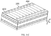
- the battery module 300 includes a plurality of battery cells 400.
- the plurality of battery cells 400 may be connected in series, in parallel or in hybrid connection mode to generate a relatively large current or voltage, where hybrid connection is a combination of series connection and parallel connection.
- the battery cell 400 may be placed upright: a height direction of the battery cell 400 is a z direction, a length direction of the battery cell 400 is an x direction, and the plurality of battery cells 400 are arranged side by side along a width direction thereof in a y direction.
- the battery cell 400 may be laid flat: a width direction of the battery cell 400 is the z direction, a length direction of the battery cell 400 is the x direction, and the plurality of battery cells 400 may be stacked by at least one layer in the z direction, where each layer includes a plurality of battery cells 400 that are arranged at intervals in the x direction.
- the battery cell 400 includes a housing 40, an electrode assembly 30, and an end cover assembly 10, where the end cover assembly 10 includes an end cover plate 10', the end cover plate 10' is connected (for example, welded) to the housing 40 to form a shell of the battery cell 400, the electrode assembly 30 is disposed in the housing 40, and the housing 40 is filled with an electrolyte.
- the battery cell 400 may be cube-shaped, cuboid-shaped, or cylinder-shaped.
- one or more electrode assemblies 30 may be provided. As shown in FIG. 1-D , at least two separately wound electrode assemblies 30 may alternatively be disposed in the battery.
- a body portion of the electrode assembly 30 may be formed by winding or stacking a first electrode plate, a second electrode plate, and a separator located between the adjacent first electrode plate and second electrode plate, where the separator is an insulator sandwiched between the adjacent first electrode plate and second electrode plate.
- the body portion has two end faces that are back away from each other.
- the first electrode plate is a positive electrode plate
- the second electrode plate is a negative electrode plate.
- a coating region of the positive electrode plate is coated with a positive electrode active substance
- a coating region of the negative electrode plate is coated with a negative electrode active substance.
- the electrode assembly includes two tabs 301: a positive tab and a negative tab.
- the positive tab extends out of the coating region of the positive electrode plate, and the negative tab extends out of the coating region of the negative electrode plate.
- the end cover assembly 10 is disposed on the top of the electrode assembly 30. As shown in FIG. 1-D , the end cover assembly 10 includes an end cover plate 10' and two electrode terminals 5, the two electrode terminals 5 include a positive electrode terminal and a negative electrode terminal, each electrode terminal 5 is correspondingly provided with a connection member 20, and the connection member 20 is located between the end cover plate 10' and the electrode assembly 30.
- the tabs 301 of the electrode assembly 30 are located on the top, the positive tab is connected to the positive electrode terminal by using one connection member 20, and the negative tab is connected to the negative electrode terminal by using the other connection member 20.
- the battery cell 400 may include two end cover assemblies 10, disposed on two ends of the housing 40 respectively, where each end cover assembly 10 is provided with a terminal 5.
- An explosion-proof member may further be disposed on the end cover plate 10', to release gas in the battery cell 400 in a timely manner when there is excessive gas in the battery cell 400, so as to avoid explosion.
- a degassing hole is provided on the end cover plate 10'.
- the degassing hole may be provided on a middle position of the end cover 10' in a length direction.
- the explosion-proof member includes a pressure relief mechanism 6, where the pressure relief mechanism 6 is disposed on the degassing hole. In a normal state, the pressure relief mechanism 6 is mounted in the degassing hole in a sealed manner. When the battery swells and gas pressure in the shell rises above a preset value, the pressure relief mechanism 6 is actuated, and gas is released by using the pressure relief mechanism 6.
- the pressure relief mechanism 6 is a component or part that can be actuated when internal pressure or internal temperature of the battery cell 400 reaches a preset threshold, to release the internal pressure and/or internal substance.
- the pressure relief mechanism 6 may specifically be in a form of an explosion-proof valve, a gas valve, a relief valve, a safety valve, or the like, or may specifically be a pressure- or temperature-sensitive component or structure.
- the pressure relief mechanism 6 performs actions or a weak structure in the pressure relief mechanism 6 is broken, so as to form an opening or channel for releasing the internal pressure.
- the threshold in this application may be a pressure threshold or a temperature threshold. Design of the threshold varies depending on different design demands.
- the threshold may be designed or determined based on an internal pressure or internal temperature value of the battery cell 400 that is considered as having a danger or runaway risk.
- the threshold may, for example, depend on the material of one or more of a positive electrode plate, a negative electrode plate, an electrolyte, and a separator in the battery cell 400.
- actuate means that the pressure relief mechanism 6 performs actions or is activated to a specific state, so that internal pressure of the battery cell 400 can be released.
- the actions generated by the pressure relief mechanism 6 may include but are not limited to: rupturing, breaking, tearing, or opening at least part of the pressure relief mechanism 6.
- the emissions from the battery cell 400 mentioned in this application include but are not limited to: electrolyte, fragments of positive and negative electrode plates and separator because of dissolution or breaking, high-temperature and high-pressure gas and flames generated by reactions, and the like.
- the high-temperature and high-pressure emissions are discharged towards a direction in which the pressure relief mechanism 6 is disposed on the battery cell 400, and more specifically, may be discharged towards a direction of an actuated region of the pressure relief mechanism 6. Power and destructive impact of the emissions may be quite large, and even may be large enough to break through one or more structures such as a cover body in this direction.
- a through-hole for injecting electrolyte into the battery cell 400 is provided on the end cover plate 10', and the through-hole may be a circular hole, an elliptical hole, a polygonal hole, or a hole in other shapes, and may extend in a height direction of the end cover plate 10'.
- An injection member 2 for sealing the through-hole is disposed on the end cover plate 10'.
- the battery 200 provided in this embodiment of this application includes a plurality of battery cells 400, a busbar 500, and an insulation part 600, where the plurality of battery cells 400 are configured to be electrically connected by using the busbar 500; the battery cell 400 further includes a pressure relief mechanism 6, where the pressure relief mechanism 6 is configured to be actuated when internal pressure or temperature of the battery cell 400 reaches a threshold, to release the internal pressure; and the insulation part 600 is configured to cover the busbar 500 to prevent emissions from the battery cell 400 from causing short circuit of at least one battery cell 400 when the pressure relief mechanism 6 is actuated.
- the busbar 500 may be electrically connected to the plurality of battery cells 400 in a welding or bolt joint manner.
- the plurality of battery cells 400 are constructed to be electrically connected by using the busbar 500, and the busbar 500 is configured to transfer a current generated by the battery cells 400, so that series connection and/or parallel connection between the plurality of battery cells 400 can be implemented.
- each battery cell 400 includes a pressure relief mechanism 6, where the pressure relief mechanism 6 is configured to be actuated when internal pressure or temperature of the battery cell 400 reaches a threshold, to release the internal pressure of the battery cell 400.
- the arrangement location and structural form of the pressure relief mechanism 6 have already been described in detail in the foregoing embodiments.
- the pressure relief mechanism 6 is disposed on the degassing hole of the end cover plate 10'. In a normal state, the pressure relief mechanism 6 is mounted in the degassing hole in a sealed manner. When the battery cell 400 swells and pressure or temperature in the shell rises above a threshold, the pressure relief mechanism 6 is actuated, and high temperature emissions such as gas in the battery cell 400 are discharged out of the pressure relief mechanism 6, so that internal pressure of the battery cell 400 can be released, to avoid exploration and other dangerous accidents.
- the insulation part 600 for covering the busbar 500 is disposed, to isolate and wrap the busbar 500, thereby reducing short circuit or high voltage spark of the battery 200.
- the battery module 300 in the battery 200 includes a plurality of battery cells 400, each battery cell 400 is provided with two electrode terminals 5, and the two electrode terminals 5 include a positive electrode terminal and a negative electrode terminal, where the positive electrode terminal is connected to the positive tab of the electrode assembly 30, and the negative electrode terminal is connected to the negative tab of the electrode assembly 30.
- the busbar 500 functions to connect the electrode terminals 5 of the adjacent battery cells 400, to implement series connection or parallel connection of the plurality of battery cells 400.
- one busbar 500 connects the electrode terminals 5 of two adjacent battery cells 400. If the connected electrode terminals 5 of the two battery cells 400 are both positive electrode terminals or negative electrode terminals, the busbar 500 implements parallel connection of the two battery cells 400. If the connected electrode terminals 5 of the two battery cells 400 include a positive electrode terminal and a negative electrode terminal, the busbar 500 implements series connection of the two battery cells 400.
- the two electrode terminals 5 may be located on a same side of the battery cell 400, or may be located on two sides of the battery cell 400. Therefore, the busbar 500 may be located on a same side of the battery cell 400, or may be located on two sides of the battery cell 400.
- the insulation part 600 provided in the embodiments of this application is mainly configured to cover the busbar 500 located on the side having the pressure relief mechanism 6, to prevent the emissions discharged out of the pressure relief mechanism 6 from directly splashing to the busbar 500 near the pressure relief mechanism 6.
- the electrode terminals 5 may be disposed on a side not having the pressure relief mechanism 6.
- the insulation part 600 may also cover the busbar 500 on the side not having the pressure relief mechanism 6, to prevent the emissions from flowing onto the busbar 500 along the battery cell 400, thereby fully covering the busbar 500.
- the battery module 300 generally includes a plurality of battery cells 400. Therefore, the busbar 500 for connecting the plurality of battery cells 400 is also provided in plurality. As shown in FIG. 3 , one electrode terminal 5 of one battery cell 400 is connected to one electrode terminal 5 of the adjacent battery cell 400 by using one busbar 500. In other words, a plurality of busbars 500 are disposed in one battery 200.
- the insulation part 600 is also provided in plurality, and each insulation part 600 covers at least one busbar 500.
- the insulation part 600 may be in a long strip shape, and one insulation part 600 covers a plurality of busbars 500 that are on a plurality of battery cells 400 and that are arranged in a same column in the y direction.
- the insulation part 600 may alternatively be set into a shape that can cover multiple columns of busbars 500.
- a length of the insulation part 600 may be the same as a total length of a plurality of battery cells 400 in a same column, and a width of the insulation part 600 may be a width of one busbar 500, or may be a width of one battery cell 400, as long as the busbar 500 can be covered to prevent the emissions discharged out of the pressure relief mechanism 6 from causing short circuit of the battery cell.
- the length and width of the insulation part 600 are not specifically limited in the embodiments of this application.
- the insulation part 600 may be set into an integral structure, to cover all the busbars 500 of the plurality of battery cells 400.
- the plurality of battery cells 400 may be in one battery module 300, or may be in a plurality of battery modules 300. This is not particularly limited in the embodiments of this application.
- the insulation part 600 needs to avoid the pressure relief mechanism 6 of the battery cell 400, so that the pressure relief mechanism 6 can be actuated properly.
- a distance between the adjacent insulation parts should be large enough to avoid the pressure relief mechanism 6 of the battery cell 400.
- a first avoidance hole 610 needs to be provided on the insulation part 600 to avoid covering the pressure relief mechanism 6, so that the emissions discharged out of the pressure relief mechanism 6 can be discharged out of the first avoidance hole 610.
- a quantity of first avoidance hole 610 needs to be the same as a quantity of pressure relief mechanisms 6, a location of the first avoidance hole 610 corresponds to a location of the pressure relief mechanism 6, and a shape of the first avoidance hole 610 may be the same as a shape of the pressure relief mechanism 6 or slightly larger than a shape of the pressure relief mechanism 6, to ensure that the emissions discharged out of the pressure relief mechanism 6 are not blocked.
- the plurality of battery cells 400 are stacked to form a battery module 300; and the insulation part 600 is configured to cover the busbar 500 located on the adjacent battery modules 300.
- the busbar 500 for connecting the two electrode terminals 5 of the adjacent battery modules 300 is arranged in a direction perpendicular to other busbars 500, and the busbar 500 may be covered by two insulation parts 600.
- the busbar 500 may alternatively be covered by one wider insulation part 600. This is not particularly limited in the embodiments of this application.
- the battery 200 may further include an isolation part 700, where the isolation part 700 is configured to mount the busbar 500.
- the isolation part 700 is disposed on the battery cell 400
- the busbar 500 is disposed on a side of the isolation part 700 back away from the battery cell 400
- the isolation part 700 further has an avoidance region 720.
- the avoidance region 720 is configured to expose at least part of the busbar 500, meaning that the avoidance region 720 is a through-hole, so that the busbar 500 is electrically connected to the battery cell 400, and specifically, the busbar 500 is connected to the electrode terminal 5 of the battery cell 400.
- the avoidance region 720 is a through-hole matching the electrode terminal 5 in shape.
- the electrode terminal 5 may be connected to the busbar 500 through the through-hole, helping save space in the battery 200, allowing the isolation part 700 to be more closely connected to the battery cell 400, and making the entire battery 200 more compact in structure.
- a second avoidance hole 710 is provided on the isolation part 700 to avoid covering the pressure relief mechanism 6, so that the emissions discharged out of the pressure relief mechanism 6 can be discharged out of the second avoidance hole 710 and the first avoidance hole 610.
- a location of the second avoidance hole 710 corresponds to a location of the first avoidance hole 610 and a location of the pressure relief mechanism 6, a quantity of second avoidance holes 710 is the same as a quantity of pressure relief mechanism 6, and a shape of the first avoidance hole 610 may be the same as a shape of the pressure relief mechanism 6 or slightly larger than a shape of the pressure relief mechanism 6, to ensure that the emissions discharged out of the pressure relief mechanism 6 are not blocked.
- the shape of the second avoidance hole 710 may be the same as the shape of the first avoidance hole 610, to facilitate machining, mounting and fastening.
- the isolation part 700 may be a harness isolation plate assembly.
- the harness isolation plate assembly and the busbar 500 may form an integrated structure by using a hot-pressing process, and the isolation part 700 may be an integrated structure that has a similar size as the battery module 300, so that the battery cells 400 in the battery module 300 are all electrically connected.
- the busbar 500 is mounted on the isolation part 700. In this way, the avoidance region 720 can be provided for the busbar 500 to connect to the electrode terminal 5. In addition, the busbar 500 can be prevented from coming into contact with other parts on the battery cell 400, thereby avoiding interference in a current transfer process.
- the insulation part 600 also needs to block the avoidance region 720, that is, blocking the avoidance region 720 while blocking the busbar 500.
- to block the busbar 500 and the avoidance region 720 means to cover the busbar 500 and the avoidance region 720.
- the insulation part 600 needs to avoid the second avoidance hole 710 while covering the busbar 500 and the avoidance region 720, so that the emissions discharged out of the pressure relief mechanism 6 can be ejected out smoothly.
- the insulation part 600 may be directly connected to the isolation part 700 outside the avoidance region 720, and the connection manner may be one or more of bonding, welding, film coating, coating, or spray-coating.
- the insulation part 600 may be at least one of the following: epoxy resin film, mica paper, electrophoresis film, asbestos layer, ceramic layer, silicon oxide film, silicon nitride film, aluminum oxide film, aluminum nitride film, polyimide film, polyethylene film, polyvinylidene fluoride film, and polytetrafluoroethylene film.
- a thickness of the insulation part 600 may be set based on actual situations.
- a thickness of the insulation part 600 may be 0.5 mm to 3 mm.
- the insulation part 600 needs to be as thin as possible, so as to save space in the battery 200 and improve energy density of the battery.
- the specific thickness of the insulation part 600 is not particularly limited in the embodiments of this application.
- the high-temperature and high-pressure emissions discharged out of the battery cell 400 are mostly discharged towards a direction of the pressure relief mechanism 6, and specifically, discharged towards a direction of a region for causing the pressure relief mechanism 6 to be actuated.
- Power and destructive impact of the emissions may be quite large, and even may be large enough to break through one or more structures in this direction, causing a safety issue.
- the battery cell 400 may continuously generate high voltage and high heat inside, causing persistent safety risks.
- a fire protection system may be disposed in a box body of the battery 200, and a fire protection pipeline 800 of the fire protection system is disposed above a side of the battery cell 400 having the pressure relief mechanism.
- the fire protection pipeline 800 is configured to accommodate a fire protection medium.
- the fire protection pipeline 800 is configured to discharge the fire protection medium to the battery cell 400 when the pressure relief mechanism 6 is actuated, so that the emissions discharged out of the pressure relief mechanism 6 can be cooled, reducing the risk of the emissions.
- the fire protection medium may also flow into the battery cell 400 through the actuated pressure relief mechanism 6, so as to further cool the battery cell 400 and enhance safety of the battery 200.
- the fire protection pipeline 800 may also be broken by the emissions that are discharged out of the battery cell 400 when the pressure relief mechanism 6 is actuated, to allow the fire protection medium in the fire protection pipeline 800 to be discharged.
- the insulation part 600 is further configured to prevent the fire protection medium flowing out of the fire protection pipeline 800 from causing short circuit of at least one battery cell 400 when the pressure relief mechanism 6 is actuated.
- the insulation part 600 provided in the embodiments of this application can not only prevent the emissions discharged out of the pressure relief mechanism 6 from causing short circuit of the battery cell 400, but also prevent the fire protection medium discharged out of the fire protection pipeline 800 from causing short circuit of the battery cell 400.
- the fire protection pipeline 800 is disposed on a position relative to the pressure relief mechanism 6.
- the isolation part 700 is disposed on the pressure relief mechanism 6, the emissions discharged out of the pressure relief mechanism 6 can be discharged through the second avoidance hole 710 of the isolation part 700. Therefore, the fire protection pipeline 800 is disposed on a position relative to the second avoidance hole 710 over the isolation part 700, so that the fire protection pipeline 800 is disposed relative to the pressure relief mechanism 6.
- the fire protection pipeline 800 includes a first region corresponding to the pressure relief mechanism 6 and a second region located on a periphery of the first region, where the first region is configured to be broken when the pressure relief mechanism 6 is actuated, to discharge the fire protection medium, and the second region is configured to remain intact when the pressure relief mechanism 6 is actuated, to allow the fire protection medium to flow from the second region to the first region.
- the fire protection pipeline 800 is configured to allow the emissions from the battery cell 400 to break the first region when the pressure relief mechanism 6 is actuated, so that the fire protection medium is discharged out of the first region and enters the battery cell 400 through the pressure relief mechanism 6.
- the fire protection pipeline 800 when the battery fails and gas pressure in the battery rises above a preset value, high-temperature and high-pressure substances in the battery cell 400 are discharged as emissions out of an actuated part of the pressure relief mechanism 6, and the high-temperature and high-pressure emissions may perforate the first region of the fire protection pipeline 800, so that the fire protection medium flows out of the fire protection pipeline 800 and flows into the battery cell 400 through the pressure relief mechanism 6, to implement fire protection in the battery cell 400.
- the high-temperature and high-pressure emissions ejected out of the battery cell 400 are used to perforate the first region of the fire protection pipeline 800, so that precision fire protection can be implemented for the failed battery cell 400. Only the first region of the fire protection pipeline 800 relative to the failed battery cell 400 is perforated, and the second region remains intact, so that the fire protection medium can flow only out of the first region, to achieve a better fire protection effect.
- the fire protection medium discharged out of the fire protection pipeline 800 can enter the battery cell 400 through the pressure relief mechanism 6, so that the foregoing precision fire protection in the embodiments of this application can increase utilization of the fire protection medium, to achieve a better fire protection effect.
- the first region may be a first weak region.
- the first weak region is configured to be broken by the emissions when the pressure relief mechanism 6 is actuated, to allow the fire protection medium to be discharged out of the first weak region, to implement fire protection.
- the first weak region is provided on the fire protection pipeline 800, to allow the high-temperature and high-pressure emissions ejected out of the battery cell 400 to more rapidly perforate the fire protection pipeline 800, thereby improving efficiency of fire protection.
- the first weak region may be weak in structure.
- a thickness of the first weak region is smaller than a thickness of other portions of the fire protection pipeline 800.
- the first weak region may be weak in material.
- a material of the first weak region may be a material that is easily broken by the high-temperature and high-pressure emissions ejected out of the battery cell 400, or a toughness of the first weak region may be less than a toughness of other portions of the fire protection pipeline 800. This is not particularly limited in the embodiments of this application.
- the fire protection medium may be fluid, and the fluid may be liquid or gas.
- the fire protection pipeline 800 may accommodate no substances.
- the fire protection pipeline 800 accommodates the fire protection medium, for example, a valve may be switched on or off to control the fire protection medium to enter the fire protection pipeline 800.
- the fire protection pipeline 800 may always accommodate the fire protection medium, and the fire protection medium may also be used to adjust temperature of the battery cell 400. To adjust temperature means to heat or cool the plurality of battery cells 400.
- the fire protection pipeline 800 is configured to accommodate cooling fluid to lower temperature of the plurality of battery cells 400.
- the fire protection pipeline 800 may also be referred to as a cooling part, a cooling system, a cooling pipeline, or the like, and the fire protection medium accommodated therein may also be referred to as a cooling medium or cooling fluid, and more specifically, cooling liquid or cooling gas.
- the fire protection medium may circulate, to implement a better temperature adjustment effect.
- the fire protection medium may be water, mixed liquid of water and glycol, air, or the like.
- the fire protection pipeline 800 may be a long strip-shaped pipeline, and a cross sectional shape of the fire protection pipeline 800 may be a square, circular, semicircular, or other shapes. This is not particularly limited in the embodiments of this application.
- a size of the fire protection pipeline 800 may be determined based on an actual size of the battery. This is not particularly limited in the embodiments of this application.
- a plurality of battery cells 400 need to be disposed in the battery 200, and the plurality of battery cells 400 may be connected in series, in parallel, or in a hybrid connection mode to form a battery module 300.
- the plurality of battery cells 400 are set into at least one battery module 300, each battery module 300 includes at least one battery cell 400, and pressure relief mechanisms 6 of the battery cells 400 in each battery module 300 are all disposed relative to one fire protection pipeline 800.
- One battery module 300 corresponds to one fire protection pipeline 800, and the pressure relief mechanisms of the battery cells 400 in the battery module 300 are all disposed relative to the fire protection pipeline 800, so that the fire protection pipeline 800 can implement fire protection on the plurality of battery cells 400 in the battery module 300, thereby reducing the number of fire protection pipelines 800 and saving costs.
- the battery 200 provided in an embodiment of this application further includes a protection part 900.
- the protection part 900 is disposed between the fire protection pipeline 800 and the battery cell 400 to protect the second region and prevent the second region from being broken by the emissions discharged out of the pressure relief mechanism 6, so as to prevent the fire protection medium in the fire protection pipeline 800 from flowing to the outside of the battery cell 400 through the second region to affect the fire protection effect.
- the protection part 900 includes a third region 910 and a fourth region 920, where the third region 910 is configured to protect the second region of the fire protection pipeline 800 when the pressure relief mechanism 6 is actuated, and the fourth region 920 is configured to allow the emissions from the battery cell 400 to pass through the fourth region 920 to break the first region when the pressure relief mechanism 6 is actuated.
- the third region 910 is a protection region
- the fourth region 920 is a second weak region.
- the second weak region allows the high-temperature and high-pressure emissions ejected out of the battery cell 400 to more rapidly perforate the protection part 900 and then perforate the fire protection pipeline 800, to improve timeliness of fire protection.
- the fire protection medium in the fire protection pipeline 800 can be discharged towards the pressure relief mechanism 6 of the battery cell 400, helping efficiently resolve safety problems caused by thermal runaway of the battery cell, rapidly lowering temperature, and improving safety performance of the battery during use.
- the second weak region may be weak in structure.
- a thickness of the second weak region is smaller than a thickness of the third region 910.
- the second weak region may be weak in material.
- a material of the second weak region may be a material that is easily broken by the high-temperature and high-pressure emissions ejected out of the battery cell 400, or a toughness of the second weak region may be less than a toughness of the third region 910.
- the second weak region is a through-hole that runs through the protection part 900. This is not particularly limited in the embodiments of this application.
- the protection part 900 is configured to form a first groove 930 for accommodating the fire protection pipeline 800, where the first groove 930 is configured to collect, when the pressure relief mechanism 6 is actuated, the fire protection medium flowing into the battery cell 400.
- the fourth region is disposed on a region that is of a bottom wall of the first groove 930 and that corresponds to the first region.
- the fire protection medium is usually ejected out of the fire protection pipeline 800 at the same time as the emissions are discharged out of the pressure relief mechanism 6, so that the fire protection medium ejected out of the fire protection pipeline 800 is quite likely to splash and flow outside the pressure relief mechanism 6, causing waste.
- the first groove 930 is used to collect the fire protection medium ejected out of the fire protection pipeline 800, so that the fire protection medium that does not flow into the battery cell 400 through the pressure relief mechanism 6 can be temporarily stored in the first groove 930, and flow into the pressure relief mechanism 6 from the first groove 930 if conditions permit.
- the foregoing conditions include that no emissions are discharged out of the pressure relief mechanism 6, that a discharge velocity is reduced, or the like. This is not particularly limited in the embodiments of this application.
- the protection part 900 is mounted on the isolation part 700.
- the protection part 900 may be fastened to the isolation part 700 in different manners.
- the protection part 900 may be clamped onto the isolation part 700 by using buckles, or may be fastened to the isolation part 700 through bonding or welding, or may be integrally molded with the isolation part 700. This is not particularly limited in the embodiments of this application.
- a second groove may be provided on the isolation part 700, and the protection part 900 is mounted in the second groove.
- the location and size of the second groove may be set based on the protection part 900. This is not particularly limited in the embodiments of this application.
- the following describes an arrangement direction of the fire protection pipeline 800 and the protection part 900 based on an arrangement direction of a plurality of battery cells 400 in a battery module 300.
- the fire protection pipeline 800 is disposed on the protection part 900, and the fire protection pipeline 800 is located between two adjacent insulation parts 600.
- one battery module 300 includes a plurality of battery cells 400 arranged in a preset direction, where a length direction of the fire protection pipeline 800 is the same as an arrangement direction of the plurality of battery cells 400. In this way, pressure relief mechanisms 6 of all the battery cells 400 are disposed relative to the fire protection pipeline 800, that is, one fire protection pipeline 800 provides fire protection services to the plurality of battery cells 400 in one battery module 300.
- the length direction of the fire protection pipeline 800 is the same as the arrangement direction of the plurality of battery cells 400, and a length direction of the protection part 900 is also the same as the arrangement direction of the plurality of battery cells 400.
- there are a plurality of first regions on the fire protection pipeline 800 there are a plurality of fourth regions 920 on the protection part 900, and a quantity of the first region and a quantity of the fourth region 920 are the same as a quantity of the pressure relief mechanisms 6.
- this application further provides an electric apparatus, where the electric apparatus is configured to receive power supplied by the foregoing battery.
- the electric apparatus is configured to receive power supplied by the foregoing battery.
- this application further provides a method for manufacturing a battery.
- FIG. 9 illustrates a method for manufacturing a battery according to this application.
- the method for manufacturing a battery may include the following steps.
- Step S910 provide a plurality of battery cells, where the battery cell includes a pressure relief mechanism, and the pressure relief mechanism is configured to be actuated when internal pressure or temperature of the battery cell reaches a threshold, to release the internal pressure.
- Step S920 electrically connect the plurality of battery cells by using a busbar.
- Step S930 cover the busbar with an insulation part, to prevent emissions from the battery cell from causing short circuit of at least one battery cell when the pressure relief mechanism is actuated.
- the pressure relief mechanism 6 needs to be prepared on the battery cell 400, and the busbar 500 is prepared to electrically connect electrode terminals 5 of the plurality of battery cells 400.
- an insulation part 600 also needs to be prepared, and the insulation part 600 covers the busbar 500.
- the insulation part 600 may cover the busbar 500 in one or more manners of bonding, welding, film coating, coating, or spray-coating.
- the battery 200 further includes other parts. These parts may be manufactured by using corresponding methods, to finally obtain the required battery 200. In actual application, any methods for manufacturing related parts and connecting related parts shall all fall within the protection scope of the embodiments of this application. Details are not described in the embodiments of this application.
- FIG. 10 is a block diagram of an apparatus for manufacturing a battery according to an embodiment of this application.
- the apparatus 1000 for manufacturing a battery may include: a first apparatus 1010, a second apparatus 1020, and a third apparatus 1030.
- the first apparatus 1010 is configured to provide a plurality of battery cells, where the battery cell includes a pressure relief mechanism, and the pressure relief mechanism is configured to be actuated when internal pressure or temperature of the battery cell reaches a threshold, to release the internal pressure.
- the second apparatus 1020 is configured to electrically connect the plurality of battery cells by using a busbar.
- the third apparatus 1030 is configured to cover the busbar with an insulation part, to prevent emissions from the battery cell from causing short circuit of at least one battery cell when the pressure relief mechanism is actuated.
Landscapes
- Chemical & Material Sciences (AREA)
- Chemical Kinetics & Catalysis (AREA)
- Electrochemistry (AREA)
- General Chemical & Material Sciences (AREA)
- Connection Of Batteries Or Terminals (AREA)
- Battery Mounting, Suspending (AREA)
- Gas Exhaust Devices For Batteries (AREA)
Abstract
Description
- This application relates to the field of battery technologies, and in particular, to a battery, an electric apparatus, and a method and an apparatus for manufacturing a battery.
- In recent years, new energy vehicles have magnificently promoted social development and environmental protection. Batteries as an important new power source are widely applied in the field of new energy vehicles.
- Currently, spontaneous combustion of batteries caused by thermal runway during use is a principal factor for safety accidents of new energy vehicles. When thermal runaway occurs in one battery cell in the battery, high temperature emissions are ejected out of the battery cell. The high temperature emissions splash to surrounding battery cells, causing severe safety accidents.
- This application provides a battery, an electric apparatus, and a method and an apparatus for manufacturing a battery, which can reduce safety accidents caused by thermal runaway of the battery.
- A first aspect of this application provides a battery, including:
- a plurality of battery cells, where the plurality of battery cells are constructed to be electrically connected by using a busbar; and
- the battery cell includes a pressure relief mechanism, and the pressure relief mechanism is configured to be actuated when internal pressure or temperature of the battery cell reaches a threshold, to release the internal pressure; and
- an insulation part, configured to cover the busbar to prevent emissions from the battery cell from causing short circuit of at least one battery cell when the pressure relief mechanism is actuated.
- In some embodiments, the insulation part and the busbar are both provided in plurality, and each insulation part covers at least one busbar.
- In some embodiments, the plurality of battery cells are stacked to form a battery module; and the insulation part is configured to cover the busbar located on the adjacent battery modules.
- In some embodiments, a thickness of the insulation part is 0.5 mm to 3 mm.
- In some embodiments, the battery further includes a fire protection pipeline, configured to accommodate a fire protection medium, where the fire protection pipeline is configured to discharge the fire protection medium to the battery cell when the pressure relief mechanism is actuated, and the insulation part is configured to prevent the fire protection medium from causing short circuit of at least one battery cell when the pressure relief mechanism is actuated.
- In some embodiments, the fire protection pipeline includes a first region corresponding to the pressure relief mechanism and a second region located on a periphery of the first region, where the first region is configured to be broken when the pressure relief mechanism is actuated, to discharge the fire protection medium, and the second region is configured to remain intact when the pressure relief mechanism is actuated, to allow the fire protection medium to flow from the second region to the first region.
- In some embodiments, the battery further includes a protection part, disposed between the fire protection pipeline and the battery cell to protect the second region.
- In some embodiments, the protection part includes a third region and a fourth region, where the third region is configured to protect the second region of the fire protection pipeline when the pressure relief mechanism is actuated, and the fourth region is configured to allow, when the pressure relief mechanism is actuated, the emissions from the battery cells to pass through the fourth region to break the first region.
- In some embodiments, the protection part is configured to form a first groove for accommodating the fire protection pipeline, where the first groove is configured to collect, when the pressure relief mechanism is actuated, the fire protection medium flowing into the battery cell.
- In some embodiments, the fourth region is provided on a region that is on a bottom wall of the first groove and that corresponds to the first region.
- In some embodiments, the battery further includes an isolation part, where the isolation part is configured to mount the busbar.
- In some embodiments, the isolation part has an avoidance region, where the avoidance region is configured to expose at least part of the busbar, to allow the busbar to be electrically connected to the battery cell.
- In some embodiments, a second groove is provided on the isolation part, and the protection part is disposed in the second groove.
- According to a second aspect of this application, an electric apparatus is provided, where the electric apparatus is configured to receive power supplied by the foregoing battery.
- According to a third aspect of this application, a method for manufacturing a battery is provided, including:
- providing a plurality of battery cells, where the battery cell includes a pressure relief mechanism, and the pressure relief mechanism is configured to be actuated when internal pressure or temperature of the battery cell reaches a threshold, to release the internal pressure;
- electrically connecting the plurality of battery cells by using a busbar; and
- covering the busbar with an insulation part, to prevent emissions from the battery cell from causing short circuit of at least one battery cell when the pressure relief mechanism is actuated.
- According to a fourth aspect of this application, an apparatus for manufacturing a battery is provided, including:
- a first apparatus, configured to provide a plurality of battery cells, where the battery cell includes a pressure relief mechanism, and the pressure relief mechanism is configured to be actuated when internal pressure or temperature of the battery cell reaches a threshold, to release the internal pressure;
- a second apparatus, configured to electrically connect the plurality of battery cells by using a busbar; and
- a third apparatus, configured to cover the busbar with an insulation part, to prevent emissions from the battery cell from causing short circuit of at least one battery cell when the pressure relief mechanism is actuated.
- According to the battery provided in the embodiments of this application, with the insulation part configured to cover the busbar, emissions discharged out of the pressure relief mechanism of the battery cell in the case of thermal runaway of the battery can be prevented from splashing to the busbar or other conductive objects, so that a probability of short circuit or high voltage spark in the battery cell can be reduced, improving battery safety during use.
- To describe the technical solutions in the embodiments of this application or in the prior art more clearly, the following briefly describes the accompanying drawings for describing the embodiments or the prior art. Apparently, the accompanying drawings in the following description show some embodiments of this application, and a person of ordinary skill in the art may still derive other drawings from these accompanying drawings without creative efforts.
- The drawings described herein are intended for a further understanding of this application and constitute a part of this application. Example embodiments of this application and descriptions thereof are intended to explain this application, and do not constitute any inappropriate limitation on this application.
-
FIG. 1-A is a schematic structural diagram of an electric apparatus according to an embodiment of this application. -
FIG. 1-B is a schematic structural diagram of a battery according to an embodiment of this application. -
FIG. 1-C is a schematic structural diagram of a battery module according to an embodiment of this application. -
FIG. 1-D is a schematic structural diagram of a battery cell according to an embodiment of this application. -
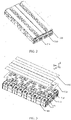
FIG. 2 is a schematic diagram of a structure inside a battery housing according to an embodiment of this application. -
FIG. 3 is a schematic exploded view of the structure shown inFIG. 2 according to an embodiment of this application. -
FIG. 4 is a schematic exploded view of another structure inside a battery housing according to an embodiment of this application. -
FIG. 5 is a schematic structural diagram of a still another structure inside a battery housing according to an embodiment of this application. -
FIG. 6 is a schematic exploded view of the structure shown inFIG. 5 according to an embodiment of this application. -
FIG. 7 is a schematic structural diagram of an isolation part and a protection part shown inFIG. 6 according to an embodiment of this application. -
FIG. 8 is a partially enlarged view of a position A inFIG. 7 according to an embodiment of this application. -
FIG. 9 is a flowchart of a method for manufacturing a battery according to an embodiment of this application. -
FIG. 10 is a block diagram of an apparatus for manufacturing a battery according to an embodiment of this application. - To make the objectives, technical solutions, and advantages of this application more comprehensible, the following describes this application in detail with reference to embodiments and accompanying drawings. It should be understood that the specific embodiments described herein are merely used to explain this application but are not intended to limit this application. Any equivalent change made based on the structure, shape, and principle of this application should fall within the protection range of this application.
- Unless otherwise defined, all technical and scientific terms used herein have the same meanings as those usually understood by a person skilled in the art of this application. The terms used in the specification of this application are for description of the particular embodiments only and are not intended to limit this application. The terms "including" and "having" and any other variations thereof in the specification, claims, and brief description of drawings of this application are intended to cover a non-exclusive inclusion.
- The term "embodiment" described herein means that specific features, structures or characteristics described with reference to the embodiments may be incorporated in at least one embodiment of this application. The word "embodiment" in various positions in the specification does not necessarily refer to the same embodiment, or refer to independent or alternative embodiments that are mutually exclusive with other embodiments. A person skilled in the art explicitly or implicitly understands that the embodiments described herein may combine with other embodiments.
- The term "and/or" in this specification is only an associative relationship for describing associated objects, indicating that three relationships may exist. For example, A and/or B may represent the following three cases: Only A exists, both A and B exist, and only B exists. In addition, the symbol "/" in this specification generally represents an "or" relationship between associated objects.
- In addition, the terms "first", "second", and the like in the specification and the claims or foregoing accompanying drawings of this application are used to distinguish between different objects but not describe a specific sequence, and may explicitly or implicitly include one or more features.
- In the descriptions of this application, unless otherwise specified, "a plurality of' indicates more than two (including two). Likewise, "multiple groups" indicates more than two groups (including two groups).
- In the descriptions of this application, it should be noted that, unless otherwise specified and defined explicitly, the terms "mount", "connected" and "connect" should be understood in a broad sense. For example, "connected" or "connect" of a mechanical structure may indicate physically connect. For example, physically connect may be fixedly connect, for example, fixedly connect by using a fixing member such as a screw, a bolt or other fixing members; or physically connect may be detachably connect, for example, connect by mutual clamping or clamping; or physically connect may be integrally connect, for example, connect by welding, bonding or integral molding. "Connected" or "connect" of a circuit structure may indicate physically connect, or may indicate electrically connect or signal connect, for example, may be directly connect, namely physically connect, may be indirectly connect by using at least one element in between as long as circuit communication is implemented, or may be communicate between two elements; and signal connect may be signal connect by using a circuit, or may be signal connect by using a media medium, such as a radio wave. A person of ordinary skill in the art can understand specific meanings of these terms in this application based on specific situations.
- To clearly describe all directions in the following embodiments, some directional words may be used. For example, directions of a battery are defined by a coordinate system in
FIG. 1-D , where an x direction represents a length direction of abattery cell 400, a y direction is perpendicular to the x direction in the horizontal plane and represents a width direction of thebattery cell 400, and a z direction is perpendicular to the x direction and the y direction and represents a height direction of the battery. In addition, expressions such as the x direction, the y direction, and the z direction that are used to describe indication directions of operations and constructions of various members of the battery in this embodiment are relative rather than absolute. Although these indications are appropriate when the members of the battery are located at the positions shown in the drawings, these directions shall be interpreted differently when the positions change, to reflect the changes. - Based on same understanding of directions, in the descriptions of this application, the directions or location relationships indicated by the terms such as "center", "longitudinal", "lateral", "length", "width", "thickness", "up", "down", "front", "rear", "left", "right", "vertical", "horizontal", "top", "bottom", "inside", "outside", "clockwise", "counterclockwise", "axial", "radial", "circumferential" are based on the directions or location relationships shown in the accompanying drawings and are merely intended to describe this application and simplify the descriptions, but not intended to indicate or imply that an apparatus or an element shall have a specific direction or be formed and operated in a specific direction, and therefore cannot be understood as a limitation on this application.
- Rechargeable batteries may be referred to as secondary batteries or traction batteries. Currently, the widely used rechargeable batteries include but are not limited to: lithium batteries, for example, lithium-sulfur batteries, sodium-lithium-ion batteries, or magnesium-ion batteries. For ease of description, rechargeable batteries herein may be collectively referred to as battery.
- Battery safety is a critical characteristic to evaluate a battery. Safety of the battery needs to be guaranteed as much as possible in use or during charging.
- The battery is generally formed by connecting a plurality of battery cells. When situations such as external short circuit, over-charging, needle piercing, and plate impact occur in the battery cell, the battery cell is prone to thermal runaway. When thermal runway occurs in the battery cell, emissions are generated inside the battery cell, including substances such as high temperature smoke (or even open flames) and volatile high-temperature electrolyte. These emissions cause thermal diffusion when being discharged, thereby causing thermal runaway to other battery cells and even causing explosion and other accidents. It may be understood that the emissions from the battery cell mentioned in this application include but are not limited to: electrolyte, fragments of positive and negative electrode plates and separator because of dissolution or breaking, high-temperature and high-pressure gas and flames generated by reactions, and the like.
- The inventors have found that thermal runaway of a battery cell, may cause short circuit, high voltage spark, or the like to surrounding battery cells.
- To resolve this problem, the inventors have found through research that the problems such as short circuit and high voltage spark in the case of thermal runaway of the battery cell are caused by emissions discharged out of the battery coming into contact with the busbar.
- In view of this, this application provides a battery, to prevent high temperature emissions ejected out of a battery cell from splashing to a busbar in the case of thermal runaway of the battery cell, reducing short circuit, high voltage spark, and other problems of the battery cell. Therefore, the battery of this application can not only control thermal runaway conditions of the battery cell in a timely manner, to prevent the battery cell from further generating heat and high temperature emissions, but also prevent the high temperature emissions from splashing to the busbar, to reduce short circuit and high voltage spark of the battery cell.
- The battery in the embodiments of this application may be applied to various electric apparatuses capable of using electric energy as a power source. The electric apparatus herein may be, but is not limited to, an electric vehicle, an electric train, an electric bicycle, a golf vehicle, an unmanned aerial vehicle, a ship, or the like. In addition, the electric apparatus may be an apparatus powered by the battery only, or may be a hybrid power type apparatus. The battery supplies electric energy to the electric apparatus, and a motor drives the electric apparatus to move.
- For example,
FIG. 1-A is a schematic structural diagram of an electric apparatus according to an embodiment of this application. The electric apparatus may be a vehicle. The vehicle may be an oil-fueled vehicle, a gas vehicle, or a new energy vehicle. The new energy vehicle may be a battery electric vehicle, a hybrid electric vehicle, an extended-range electric vehicle, or the like. The vehicle includes abattery 200, acontroller 210, and amotor 220. Thebattery 200 is configured to supply power to thecontroller 210 and themotor 220 as an operational power supply and a driving power supply of the vehicle. For example, thebattery 200 is configured to supply power to meet start, navigation, and operation requirements of the vehicle. For example, thebattery 200 supplies power to thecontroller 210. Thecontroller 210 controls thebattery 200 to supply power to themotor 220. Themotor 220 receives and uses the power of thebattery 200 as the driving power supply of the vehicle, to replace or partially replace fuel oil or natural gas to supply driving power to the vehicle. - To make the battery function better to meet use requirements, the
battery 200 may include a plurality ofbattery modules 300 that are connected to each other. As shown inFIG. 1-B , thebattery 200 includes afirst housing 201, asecond housing 202, and a plurality ofbattery modules 300, where thefirst housing 201 and thesecond housing 202 are snap-fitted together, and the plurality ofbattery modules 300 are arranged in a space enclosed by thefirst housing 201 and thesecond housing 202. - As shown in
FIG. 1-C , thebattery module 300 includes a plurality ofbattery cells 400. The plurality ofbattery cells 400 may be connected in series, in parallel or in hybrid connection mode to generate a relatively large current or voltage, where hybrid connection is a combination of series connection and parallel connection. Still referring toFIG. 1-C , thebattery cell 400 may be placed upright: a height direction of thebattery cell 400 is a z direction, a length direction of thebattery cell 400 is an x direction, and the plurality ofbattery cells 400 are arranged side by side along a width direction thereof in a y direction. Alternatively, thebattery cell 400 may be laid flat: a width direction of thebattery cell 400 is the z direction, a length direction of thebattery cell 400 is the x direction, and the plurality ofbattery cells 400 may be stacked by at least one layer in the z direction, where each layer includes a plurality ofbattery cells 400 that are arranged at intervals in the x direction. - To make a person skilled in the art clearly understand improvements of this application, an entire structure of the
battery cell 400 is described first. - As shown in
FIG. 1-D , thebattery cell 400 includes ahousing 40, anelectrode assembly 30, and anend cover assembly 10, where theend cover assembly 10 includes an end cover plate 10', the end cover plate 10' is connected (for example, welded) to thehousing 40 to form a shell of thebattery cell 400, theelectrode assembly 30 is disposed in thehousing 40, and thehousing 40 is filled with an electrolyte. Thebattery cell 400 may be cube-shaped, cuboid-shaped, or cylinder-shaped. - Based on actual use requirements, one or
more electrode assemblies 30 may be provided. As shown inFIG. 1-D , at least two separately woundelectrode assemblies 30 may alternatively be disposed in the battery. A body portion of theelectrode assembly 30 may be formed by winding or stacking a first electrode plate, a second electrode plate, and a separator located between the adjacent first electrode plate and second electrode plate, where the separator is an insulator sandwiched between the adjacent first electrode plate and second electrode plate. The body portion has two end faces that are back away from each other. In this embodiment, the first electrode plate is a positive electrode plate, and the second electrode plate is a negative electrode plate. A coating region of the positive electrode plate is coated with a positive electrode active substance, and a coating region of the negative electrode plate is coated with a negative electrode active substance. A plurality of non-coating regions extending out of the coating regions of the body portion are stacked to form tabs. The electrode assembly includes two tabs 301: a positive tab and a negative tab. The positive tab extends out of the coating region of the positive electrode plate, and the negative tab extends out of the coating region of the negative electrode plate. - The
end cover assembly 10 is disposed on the top of theelectrode assembly 30. As shown inFIG. 1-D , theend cover assembly 10 includes an end cover plate 10' and twoelectrode terminals 5, the twoelectrode terminals 5 include a positive electrode terminal and a negative electrode terminal, eachelectrode terminal 5 is correspondingly provided with aconnection member 20, and theconnection member 20 is located between the end cover plate 10' and theelectrode assembly 30. - For example, as shown in
FIG. 1-D , thetabs 301 of theelectrode assembly 30 are located on the top, the positive tab is connected to the positive electrode terminal by using oneconnection member 20, and the negative tab is connected to the negative electrode terminal by using theother connection member 20. Optionally, thebattery cell 400 may include twoend cover assemblies 10, disposed on two ends of thehousing 40 respectively, where eachend cover assembly 10 is provided with aterminal 5. - An explosion-proof member may further be disposed on the end cover plate 10', to release gas in the
battery cell 400 in a timely manner when there is excessive gas in thebattery cell 400, so as to avoid explosion. - A degassing hole is provided on the end cover plate 10'. The degassing hole may be provided on a middle position of the end cover 10' in a length direction. The explosion-proof member includes a
pressure relief mechanism 6, where thepressure relief mechanism 6 is disposed on the degassing hole. In a normal state, thepressure relief mechanism 6 is mounted in the degassing hole in a sealed manner. When the battery swells and gas pressure in the shell rises above a preset value, thepressure relief mechanism 6 is actuated, and gas is released by using thepressure relief mechanism 6. - The
pressure relief mechanism 6 is a component or part that can be actuated when internal pressure or internal temperature of thebattery cell 400 reaches a preset threshold, to release the internal pressure and/or internal substance. Thepressure relief mechanism 6 may specifically be in a form of an explosion-proof valve, a gas valve, a relief valve, a safety valve, or the like, or may specifically be a pressure- or temperature-sensitive component or structure. To be specific, when internal pressure or temperature of thebattery cell 400 reaches a preset threshold, thepressure relief mechanism 6 performs actions or a weak structure in thepressure relief mechanism 6 is broken, so as to form an opening or channel for releasing the internal pressure. The threshold in this application may be a pressure threshold or a temperature threshold. Design of the threshold varies depending on different design demands. For example, the threshold may be designed or determined based on an internal pressure or internal temperature value of thebattery cell 400 that is considered as having a danger or runaway risk. In addition, the threshold may, for example, depend on the material of one or more of a positive electrode plate, a negative electrode plate, an electrolyte, and a separator in thebattery cell 400. - The term "actuate" mentioned in this application means that the
pressure relief mechanism 6 performs actions or is activated to a specific state, so that internal pressure of thebattery cell 400 can be released. The actions generated by thepressure relief mechanism 6 may include but are not limited to: rupturing, breaking, tearing, or opening at least part of thepressure relief mechanism 6. When thepressure relief mechanism 6 is actuated, high-temperature and high-pressure substances in thebattery cell 400 are discharged as emissions out of an actuated part. In this way, thebattery cell 400 can release pressure in the case of controllable pressure or temperature, thereby avoiding potential and more serious accidents. The emissions from thebattery cell 400 mentioned in this application include but are not limited to: electrolyte, fragments of positive and negative electrode plates and separator because of dissolution or breaking, high-temperature and high-pressure gas and flames generated by reactions, and the like. The high-temperature and high-pressure emissions are discharged towards a direction in which thepressure relief mechanism 6 is disposed on thebattery cell 400, and more specifically, may be discharged towards a direction of an actuated region of thepressure relief mechanism 6. Power and destructive impact of the emissions may be quite large, and even may be large enough to break through one or more structures such as a cover body in this direction. - In some embodiments, as shown in
FIG. 1-D , a through-hole for injecting electrolyte into thebattery cell 400 is provided on the end cover plate 10', and the through-hole may be a circular hole, an elliptical hole, a polygonal hole, or a hole in other shapes, and may extend in a height direction of the end cover plate 10'. An injection member 2 for sealing the through-hole is disposed on the end cover plate 10'. - As shown in
FIG. 2 and FIG. 3 , thebattery 200 provided in this embodiment of this application includes a plurality ofbattery cells 400, abusbar 500, and aninsulation part 600, where the plurality ofbattery cells 400 are configured to be electrically connected by using thebusbar 500; thebattery cell 400 further includes apressure relief mechanism 6, where thepressure relief mechanism 6 is configured to be actuated when internal pressure or temperature of thebattery cell 400 reaches a threshold, to release the internal pressure; and theinsulation part 600 is configured to cover thebusbar 500 to prevent emissions from thebattery cell 400 from causing short circuit of at least onebattery cell 400 when thepressure relief mechanism 6 is actuated. - In actual application, the
busbar 500 may be electrically connected to the plurality ofbattery cells 400 in a welding or bolt joint manner. In the embodiments of this application, the plurality ofbattery cells 400 are constructed to be electrically connected by using thebusbar 500, and thebusbar 500 is configured to transfer a current generated by thebattery cells 400, so that series connection and/or parallel connection between the plurality ofbattery cells 400 can be implemented. - In the embodiments of this application, each
battery cell 400 includes apressure relief mechanism 6, where thepressure relief mechanism 6 is configured to be actuated when internal pressure or temperature of thebattery cell 400 reaches a threshold, to release the internal pressure of thebattery cell 400. The arrangement location and structural form of thepressure relief mechanism 6 have already been described in detail in the foregoing embodiments. - As described above, the
pressure relief mechanism 6 is disposed on the degassing hole of the end cover plate 10'. In a normal state, thepressure relief mechanism 6 is mounted in the degassing hole in a sealed manner. When thebattery cell 400 swells and pressure or temperature in the shell rises above a threshold, thepressure relief mechanism 6 is actuated, and high temperature emissions such as gas in thebattery cell 400 are discharged out of thepressure relief mechanism 6, so that internal pressure of thebattery cell 400 can be released, to avoid exploration and other dangerous accidents. - When one or
more battery cells 400 fail and emissions are discharged out of thepressure relief mechanism 6, some emissions may splash to thebusbar 500, making positive and negative electrodes of somebattery cells 400 to be directly connected and causing short circuit. In the embodiments of this application, theinsulation part 600 for covering thebusbar 500 is disposed, to isolate and wrap thebusbar 500, thereby reducing short circuit or high voltage spark of thebattery 200. - As shown in
FIG. 1-B ,FIG. 1-C andFIG. 1-D , thebattery module 300 in thebattery 200 includes a plurality ofbattery cells 400, eachbattery cell 400 is provided with twoelectrode terminals 5, and the twoelectrode terminals 5 include a positive electrode terminal and a negative electrode terminal, where the positive electrode terminal is connected to the positive tab of theelectrode assembly 30, and the negative electrode terminal is connected to the negative tab of theelectrode assembly 30. - As shown in
FIG. 3 , in thebattery 200, thebusbar 500 functions to connect theelectrode terminals 5 of theadjacent battery cells 400, to implement series connection or parallel connection of the plurality ofbattery cells 400. - Still referring to
FIG. 3 , onebusbar 500 connects theelectrode terminals 5 of twoadjacent battery cells 400. If theconnected electrode terminals 5 of the twobattery cells 400 are both positive electrode terminals or negative electrode terminals, thebusbar 500 implements parallel connection of the twobattery cells 400. If theconnected electrode terminals 5 of the twobattery cells 400 include a positive electrode terminal and a negative electrode terminal, thebusbar 500 implements series connection of the twobattery cells 400. - In actual application, the two
electrode terminals 5 may be located on a same side of thebattery cell 400, or may be located on two sides of thebattery cell 400. Therefore, thebusbar 500 may be located on a same side of thebattery cell 400, or may be located on two sides of thebattery cell 400. - In this application, because the
electrode terminals 5 are disposed on a side of thebattery cell 400 having thepressure relief mechanism 6, theinsulation part 600 provided in the embodiments of this application is mainly configured to cover thebusbar 500 located on the side having thepressure relief mechanism 6, to prevent the emissions discharged out of thepressure relief mechanism 6 from directly splashing to thebusbar 500 near thepressure relief mechanism 6. - Certainly, in actual application, the
electrode terminals 5 may be disposed on a side not having thepressure relief mechanism 6. In this case, to further reduce a probability of short circuit or high voltage spark of thebattery cell 400, theinsulation part 600 may also cover thebusbar 500 on the side not having thepressure relief mechanism 6, to prevent the emissions from flowing onto thebusbar 500 along thebattery cell 400, thereby fully covering thebusbar 500. - The
battery module 300 generally includes a plurality ofbattery cells 400. Therefore, thebusbar 500 for connecting the plurality ofbattery cells 400 is also provided in plurality. As shown inFIG. 3 , oneelectrode terminal 5 of onebattery cell 400 is connected to oneelectrode terminal 5 of theadjacent battery cell 400 by using onebusbar 500. In other words, a plurality ofbusbars 500 are disposed in onebattery 200. - In the embodiments of this application, the
insulation part 600 is also provided in plurality, and eachinsulation part 600 covers at least onebusbar 500. - Optionally, in the embodiments of this application, as shown in
FIG. 3 , theinsulation part 600 may be in a long strip shape, and oneinsulation part 600 covers a plurality ofbusbars 500 that are on a plurality ofbattery cells 400 and that are arranged in a same column in the y direction. Likewise, theinsulation part 600 may alternatively be set into a shape that can cover multiple columns ofbusbars 500. That is, a length of theinsulation part 600 may be the same as a total length of a plurality ofbattery cells 400 in a same column, and a width of theinsulation part 600 may be a width of onebusbar 500, or may be a width of onebattery cell 400, as long as thebusbar 500 can be covered to prevent the emissions discharged out of thepressure relief mechanism 6 from causing short circuit of the battery cell. The length and width of theinsulation part 600 are not specifically limited in the embodiments of this application. - Optionally, in the embodiments of this application, as shown in
FIG. 4 , theinsulation part 600 may be set into an integral structure, to cover all thebusbars 500 of the plurality ofbattery cells 400. The plurality ofbattery cells 400 may be in onebattery module 300, or may be in a plurality ofbattery modules 300. This is not particularly limited in the embodiments of this application. - In actual application, to prevent the
insulation part 600 from blocking thepressure relief mechanism 6 and causing the pressure relief mechanism unable to be actuated, theinsulation part 600 needs to avoid thepressure relief mechanism 6 of thebattery cell 400, so that thepressure relief mechanism 6 can be actuated properly. For example, when theinsulation part 600 is long strip-shaped, a distance between the adjacent insulation parts should be large enough to avoid thepressure relief mechanism 6 of thebattery cell 400. - However, if the
insulation part 600 is so wide that thepressure relief mechanism 6 is covered, or theinsulation part 600 is set into an integral structure, afirst avoidance hole 610 needs to be provided on theinsulation part 600 to avoid covering thepressure relief mechanism 6, so that the emissions discharged out of thepressure relief mechanism 6 can be discharged out of thefirst avoidance hole 610. - In actual application, a quantity of
first avoidance hole 610 needs to be the same as a quantity ofpressure relief mechanisms 6, a location of thefirst avoidance hole 610 corresponds to a location of thepressure relief mechanism 6, and a shape of thefirst avoidance hole 610 may be the same as a shape of thepressure relief mechanism 6 or slightly larger than a shape of thepressure relief mechanism 6, to ensure that the emissions discharged out of thepressure relief mechanism 6 are not blocked. - In actual application, the plurality of
battery cells 400 are stacked to form abattery module 300; and theinsulation part 600 is configured to cover thebusbar 500 located on theadjacent battery modules 300. As shown inFIG. 3 , thebusbar 500 for connecting the twoelectrode terminals 5 of theadjacent battery modules 300 is arranged in a direction perpendicular toother busbars 500, and thebusbar 500 may be covered by twoinsulation parts 600. Thebusbar 500 may alternatively be covered by onewider insulation part 600. This is not particularly limited in the embodiments of this application. - In actual application, the
battery 200 may further include anisolation part 700, where theisolation part 700 is configured to mount thebusbar 500. As shown inFIG. 3 , theisolation part 700 is disposed on thebattery cell 400, thebusbar 500 is disposed on a side of theisolation part 700 back away from thebattery cell 400, and theisolation part 700 further has anavoidance region 720. As shown inFIG. 4 , theavoidance region 720 is configured to expose at least part of thebusbar 500, meaning that theavoidance region 720 is a through-hole, so that thebusbar 500 is electrically connected to thebattery cell 400, and specifically, thebusbar 500 is connected to theelectrode terminal 5 of thebattery cell 400. - In an embodiment of this application, the
avoidance region 720 is a through-hole matching theelectrode terminal 5 in shape. Theelectrode terminal 5 may be connected to thebusbar 500 through the through-hole, helping save space in thebattery 200, allowing theisolation part 700 to be more closely connected to thebattery cell 400, and making theentire battery 200 more compact in structure. - In an embodiment of this application, to prevent the
isolation part 700 from blocking thepressure relief mechanism 6, asecond avoidance hole 710 is provided on theisolation part 700 to avoid covering thepressure relief mechanism 6, so that the emissions discharged out of thepressure relief mechanism 6 can be discharged out of thesecond avoidance hole 710 and thefirst avoidance hole 610. - In actual application, a location of the
second avoidance hole 710 corresponds to a location of thefirst avoidance hole 610 and a location of thepressure relief mechanism 6, a quantity of second avoidance holes 710 is the same as a quantity ofpressure relief mechanism 6, and a shape of thefirst avoidance hole 610 may be the same as a shape of thepressure relief mechanism 6 or slightly larger than a shape of thepressure relief mechanism 6, to ensure that the emissions discharged out of thepressure relief mechanism 6 are not blocked. In addition, the shape of thesecond avoidance hole 710 may be the same as the shape of thefirst avoidance hole 610, to facilitate machining, mounting and fastening. - In the embodiments of this application, the
isolation part 700 may be a harness isolation plate assembly. The harness isolation plate assembly and thebusbar 500 may form an integrated structure by using a hot-pressing process, and theisolation part 700 may be an integrated structure that has a similar size as thebattery module 300, so that thebattery cells 400 in thebattery module 300 are all electrically connected. - In an embodiment of this application, as shown in
FIG. 3 andFIG. 4 , thebusbar 500 is mounted on theisolation part 700. In this way, theavoidance region 720 can be provided for thebusbar 500 to connect to theelectrode terminal 5. In addition, thebusbar 500 can be prevented from coming into contact with other parts on thebattery cell 400, thereby avoiding interference in a current transfer process. - Further, in an embodiment of this application, to prevent the emissions discharged out of the
pressure relief mechanism 6 from flowing to thebattery cell 400 through theavoidance region 720 and causing short circuit of at least onebattery cell 400, theinsulation part 600 also needs to block theavoidance region 720, that is, blocking theavoidance region 720 while blocking thebusbar 500. - In actual application, to block the
busbar 500 and theavoidance region 720 means to cover thebusbar 500 and theavoidance region 720. In addition, theinsulation part 600 needs to avoid thesecond avoidance hole 710 while covering thebusbar 500 and theavoidance region 720, so that the emissions discharged out of thepressure relief mechanism 6 can be ejected out smoothly. - Optionally, in actual application, to cover the
busbar 500, theinsulation part 600 may be directly connected to theisolation part 700 outside theavoidance region 720, and the connection manner may be one or more of bonding, welding, film coating, coating, or spray-coating. - Optionally, in an embodiment of this application, the
insulation part 600 may be at least one of the following: epoxy resin film, mica paper, electrophoresis film, asbestos layer, ceramic layer, silicon oxide film, silicon nitride film, aluminum oxide film, aluminum nitride film, polyimide film, polyethylene film, polyvinylidene fluoride film, and polytetrafluoroethylene film. - In actual application, a thickness of the
insulation part 600 may be set based on actual situations. For example, a thickness of theinsulation part 600 may be 0.5 mm to 3 mm. Under the condition of sufficient corrosion resistance is satisfied, that is, not broken by corrosion caused by the high-temperature and high-pressure emissions, theinsulation part 600 needs to be as thin as possible, so as to save space in thebattery 200 and improve energy density of the battery. The specific thickness of theinsulation part 600 is not particularly limited in the embodiments of this application. - In actual application, the high-temperature and high-pressure emissions discharged out of the
battery cell 400 are mostly discharged towards a direction of thepressure relief mechanism 6, and specifically, discharged towards a direction of a region for causing thepressure relief mechanism 6 to be actuated. Power and destructive impact of the emissions may be quite large, and even may be large enough to break through one or more structures in this direction, causing a safety issue. In addition, after thermal runaway occurs in thebattery cell 400, thebattery cell 400 may continuously generate high voltage and high heat inside, causing persistent safety risks. - To resolve the foregoing problems, in an embodiment of this application, as shown in
FIG. 6 , a fire protection system may be disposed in a box body of thebattery 200, and afire protection pipeline 800 of the fire protection system is disposed above a side of thebattery cell 400 having the pressure relief mechanism. Thefire protection pipeline 800 is configured to accommodate a fire protection medium. Thefire protection pipeline 800 is configured to discharge the fire protection medium to thebattery cell 400 when thepressure relief mechanism 6 is actuated, so that the emissions discharged out of thepressure relief mechanism 6 can be cooled, reducing the risk of the emissions. The fire protection medium may also flow into thebattery cell 400 through the actuatedpressure relief mechanism 6, so as to further cool thebattery cell 400 and enhance safety of thebattery 200. In addition, thefire protection pipeline 800 may also be broken by the emissions that are discharged out of thebattery cell 400 when thepressure relief mechanism 6 is actuated, to allow the fire protection medium in thefire protection pipeline 800 to be discharged. - In an embodiment of this application, the
insulation part 600 is further configured to prevent the fire protection medium flowing out of thefire protection pipeline 800 from causing short circuit of at least onebattery cell 400 when thepressure relief mechanism 6 is actuated. In other words, theinsulation part 600 provided in the embodiments of this application can not only prevent the emissions discharged out of thepressure relief mechanism 6 from causing short circuit of thebattery cell 400, but also prevent the fire protection medium discharged out of thefire protection pipeline 800 from causing short circuit of thebattery cell 400. - In actual application, to allow the fire protection medium discharged out of the
fire protection pipeline 800 to directly enter thebattery cell 400 through thepressure relief mechanism 6, thefire protection pipeline 800 is disposed on a position relative to thepressure relief mechanism 6. In the embodiments of this application, because theisolation part 700 is disposed on thepressure relief mechanism 6, the emissions discharged out of thepressure relief mechanism 6 can be discharged through thesecond avoidance hole 710 of theisolation part 700. Therefore, thefire protection pipeline 800 is disposed on a position relative to thesecond avoidance hole 710 over theisolation part 700, so that thefire protection pipeline 800 is disposed relative to thepressure relief mechanism 6. - In an embodiment of this application, the
fire protection pipeline 800 includes a first region corresponding to thepressure relief mechanism 6 and a second region located on a periphery of the first region, where the first region is configured to be broken when thepressure relief mechanism 6 is actuated, to discharge the fire protection medium, and the second region is configured to remain intact when thepressure relief mechanism 6 is actuated, to allow the fire protection medium to flow from the second region to the first region. - In the embodiments of this application, the
fire protection pipeline 800 is configured to allow the emissions from thebattery cell 400 to break the first region when thepressure relief mechanism 6 is actuated, so that the fire protection medium is discharged out of the first region and enters thebattery cell 400 through thepressure relief mechanism 6. To be specific, when the battery fails and gas pressure in the battery rises above a preset value, high-temperature and high-pressure substances in thebattery cell 400 are discharged as emissions out of an actuated part of thepressure relief mechanism 6, and the high-temperature and high-pressure emissions may perforate the first region of thefire protection pipeline 800, so that the fire protection medium flows out of thefire protection pipeline 800 and flows into thebattery cell 400 through thepressure relief mechanism 6, to implement fire protection in thebattery cell 400. - In the embodiments of this application, the high-temperature and high-pressure emissions ejected out of the
battery cell 400 are used to perforate the first region of thefire protection pipeline 800, so that precision fire protection can be implemented for the failedbattery cell 400. Only the first region of thefire protection pipeline 800 relative to the failedbattery cell 400 is perforated, and the second region remains intact, so that the fire protection medium can flow only out of the first region, to achieve a better fire protection effect. - In actual application, the fire protection medium discharged out of the
fire protection pipeline 800 can enter thebattery cell 400 through thepressure relief mechanism 6, so that the foregoing precision fire protection in the embodiments of this application can increase utilization of the fire protection medium, to achieve a better fire protection effect. - In an embodiment of this application, to allow the first region of the
fire protection pipeline 800 to be perforated, the first region may be a first weak region. The first weak region is configured to be broken by the emissions when thepressure relief mechanism 6 is actuated, to allow the fire protection medium to be discharged out of the first weak region, to implement fire protection. - In the embodiments of this application, the first weak region is provided on the
fire protection pipeline 800, to allow the high-temperature and high-pressure emissions ejected out of thebattery cell 400 to more rapidly perforate thefire protection pipeline 800, thereby improving efficiency of fire protection. - In the embodiments of this application, the first weak region may be weak in structure. For example, a thickness of the first weak region is smaller than a thickness of other portions of the
fire protection pipeline 800. Alternatively, the first weak region may be weak in material. For example, a material of the first weak region may be a material that is easily broken by the high-temperature and high-pressure emissions ejected out of thebattery cell 400, or a toughness of the first weak region may be less than a toughness of other portions of thefire protection pipeline 800. This is not particularly limited in the embodiments of this application. - In actual application, the fire protection medium may be fluid, and the fluid may be liquid or gas. When the
pressure relief mechanism 6 does not break thefire protection pipeline 800, thefire protection pipeline 800 may accommodate no substances. When thepressure relief mechanism 6 is actuated, thefire protection pipeline 800 accommodates the fire protection medium, for example, a valve may be switched on or off to control the fire protection medium to enter thefire protection pipeline 800. Alternatively, when thepressure relief mechanism 6 is not broken, thefire protection pipeline 800 may always accommodate the fire protection medium, and the fire protection medium may also be used to adjust temperature of thebattery cell 400. To adjust temperature means to heat or cool the plurality ofbattery cells 400. In a case of cooling or lowering temperature of thebattery cells 400, thefire protection pipeline 800 is configured to accommodate cooling fluid to lower temperature of the plurality ofbattery cells 400. In this case, thefire protection pipeline 800 may also be referred to as a cooling part, a cooling system, a cooling pipeline, or the like, and the fire protection medium accommodated therein may also be referred to as a cooling medium or cooling fluid, and more specifically, cooling liquid or cooling gas. Optionally, the fire protection medium may circulate, to implement a better temperature adjustment effect. Optionally, the fire protection medium may be water, mixed liquid of water and glycol, air, or the like. - In an embodiment of this application, the
fire protection pipeline 800 may be a long strip-shaped pipeline, and a cross sectional shape of thefire protection pipeline 800 may be a square, circular, semicircular, or other shapes. This is not particularly limited in the embodiments of this application. A size of thefire protection pipeline 800 may be determined based on an actual size of the battery. This is not particularly limited in the embodiments of this application. - In actual application, generally a plurality of
battery cells 400 need to be disposed in thebattery 200, and the plurality ofbattery cells 400 may be connected in series, in parallel, or in a hybrid connection mode to form abattery module 300. - In an embodiment of this application, the plurality of
battery cells 400 are set into at least onebattery module 300, eachbattery module 300 includes at least onebattery cell 400, andpressure relief mechanisms 6 of thebattery cells 400 in eachbattery module 300 are all disposed relative to onefire protection pipeline 800. - One
battery module 300 corresponds to onefire protection pipeline 800, and the pressure relief mechanisms of thebattery cells 400 in thebattery module 300 are all disposed relative to thefire protection pipeline 800, so that thefire protection pipeline 800 can implement fire protection on the plurality ofbattery cells 400 in thebattery module 300, thereby reducing the number offire protection pipelines 800 and saving costs. - As shown in
FIG. 7 , thebattery 200 provided in an embodiment of this application further includes aprotection part 900. Theprotection part 900 is disposed between thefire protection pipeline 800 and thebattery cell 400 to protect the second region and prevent the second region from being broken by the emissions discharged out of thepressure relief mechanism 6, so as to prevent the fire protection medium in thefire protection pipeline 800 from flowing to the outside of thebattery cell 400 through the second region to affect the fire protection effect. - In an embodiment of this application, the
protection part 900 includes athird region 910 and afourth region 920, where thethird region 910 is configured to protect the second region of thefire protection pipeline 800 when thepressure relief mechanism 6 is actuated, and thefourth region 920 is configured to allow the emissions from thebattery cell 400 to pass through thefourth region 920 to break the first region when thepressure relief mechanism 6 is actuated. - In actual application, the
third region 910 is a protection region, and thefourth region 920 is a second weak region. The second weak region allows the high-temperature and high-pressure emissions ejected out of thebattery cell 400 to more rapidly perforate theprotection part 900 and then perforate thefire protection pipeline 800, to improve timeliness of fire protection. With arrangement of both the protection region and the weak region, the fire protection medium in thefire protection pipeline 800 can be discharged towards thepressure relief mechanism 6 of thebattery cell 400, helping efficiently resolve safety problems caused by thermal runaway of the battery cell, rapidly lowering temperature, and improving safety performance of the battery during use. - In the embodiments of this application, the second weak region may be weak in structure. For example, a thickness of the second weak region is smaller than a thickness of the
third region 910. Alternatively, the second weak region may be weak in material. For example, a material of the second weak region may be a material that is easily broken by the high-temperature and high-pressure emissions ejected out of thebattery cell 400, or a toughness of the second weak region may be less than a toughness of thethird region 910. Alternatively, the second weak region is a through-hole that runs through theprotection part 900. This is not particularly limited in the embodiments of this application. - In an embodiment of this application, as shown in
FIG. 8 , theprotection part 900 is configured to form afirst groove 930 for accommodating thefire protection pipeline 800, where thefirst groove 930 is configured to collect, when thepressure relief mechanism 6 is actuated, the fire protection medium flowing into thebattery cell 400. The fourth region is disposed on a region that is of a bottom wall of thefirst groove 930 and that corresponds to the first region. - It should be noted that, in actual application, the fire protection medium is usually ejected out of the
fire protection pipeline 800 at the same time as the emissions are discharged out of thepressure relief mechanism 6, so that the fire protection medium ejected out of thefire protection pipeline 800 is quite likely to splash and flow outside thepressure relief mechanism 6, causing waste. In the embodiments of this application, with arrangement of thefirst groove 930, thefirst groove 930 is used to collect the fire protection medium ejected out of thefire protection pipeline 800, so that the fire protection medium that does not flow into thebattery cell 400 through thepressure relief mechanism 6 can be temporarily stored in thefirst groove 930, and flow into thepressure relief mechanism 6 from thefirst groove 930 if conditions permit. For example, the foregoing conditions include that no emissions are discharged out of thepressure relief mechanism 6, that a discharge velocity is reduced, or the like. This is not particularly limited in the embodiments of this application. - In the
battery 200 provided in the embodiments of this application, with thefirst groove 930 provided on theprotection part 900, more fire protection medium discharged out of thefire protection pipeline 800 can enter thebattery cell 400 through thepressure relief mechanism 6, so that utilization of the fire protection medium is increased, to implement a better fire protection effect. - In actual application, the
protection part 900 is mounted on theisolation part 700. In addition, theprotection part 900 may be fastened to theisolation part 700 in different manners. For example, theprotection part 900 may be clamped onto theisolation part 700 by using buckles, or may be fastened to theisolation part 700 through bonding or welding, or may be integrally molded with theisolation part 700. This is not particularly limited in the embodiments of this application. - When the
protection part 900 is disposed on theisolation part 700, a second groove may be provided on theisolation part 700, and theprotection part 900 is mounted in the second groove. The location and size of the second groove may be set based on theprotection part 900. This is not particularly limited in the embodiments of this application. - The following describes an arrangement direction of the
fire protection pipeline 800 and theprotection part 900 based on an arrangement direction of a plurality ofbattery cells 400 in abattery module 300. - As shown in
FIG. 6 , thefire protection pipeline 800 is disposed on theprotection part 900, and thefire protection pipeline 800 is located between twoadjacent insulation parts 600. In an embodiment of this application, onebattery module 300 includes a plurality ofbattery cells 400 arranged in a preset direction, where a length direction of thefire protection pipeline 800 is the same as an arrangement direction of the plurality ofbattery cells 400. In this way,pressure relief mechanisms 6 of all thebattery cells 400 are disposed relative to thefire protection pipeline 800, that is, onefire protection pipeline 800 provides fire protection services to the plurality ofbattery cells 400 in onebattery module 300. - In the foregoing embodiment, the length direction of the
fire protection pipeline 800 is the same as the arrangement direction of the plurality ofbattery cells 400, and a length direction of theprotection part 900 is also the same as the arrangement direction of the plurality ofbattery cells 400. In addition, there are a plurality of first regions on thefire protection pipeline 800, there are a plurality offourth regions 920 on theprotection part 900, and a quantity of the first region and a quantity of thefourth region 920 are the same as a quantity of thepressure relief mechanisms 6. - In another aspect, this application further provides an electric apparatus, where the electric apparatus is configured to receive power supplied by the foregoing battery. A specific structural form and operating principle of the
battery 200 have already been described in detail in the foregoing embodiments. Details are not described in this embodiment again. - In conclusion, in the electric apparatus in this embodiment of this application, with arrangement of the foregoing battery, the insulation part on the battery, and the insulation part configured to cover the busbar, emissions discharged out of one or more failed battery cells can be partly prevented from splashing to conductive objects such as the busbar, so that a probability of short circuit or high voltage spark of the battery cell can be reduced.
- In another aspect, this application further provides a method for manufacturing a battery.
FIG. 9 illustrates a method for manufacturing a battery according to this application. The method for manufacturing a battery may include the following steps. - Step S910: provide a plurality of battery cells, where the battery cell includes a pressure relief mechanism, and the pressure relief mechanism is configured to be actuated when internal pressure or temperature of the battery cell reaches a threshold, to release the internal pressure.
- Step S920: electrically connect the plurality of battery cells by using a busbar.
- Step S930: cover the busbar with an insulation part, to prevent emissions from the battery cell from causing short circuit of at least one battery cell when the pressure relief mechanism is actuated.
- It may be learned from the battery embodiments that, the
pressure relief mechanism 6 needs to be prepared on thebattery cell 400, and thebusbar 500 is prepared to electrically connectelectrode terminals 5 of the plurality ofbattery cells 400. - In this embodiment of this application, an
insulation part 600 also needs to be prepared, and theinsulation part 600 covers thebusbar 500. Specifically, theinsulation part 600 may cover thebusbar 500 in one or more manners of bonding, welding, film coating, coating, or spray-coating. - It may be learned from the embodiments of the
battery 200 that, thebattery 200 further includes other parts. These parts may be manufactured by using corresponding methods, to finally obtain the requiredbattery 200. In actual application, any methods for manufacturing related parts and connecting related parts shall all fall within the protection scope of the embodiments of this application. Details are not described in the embodiments of this application. - In another aspect, this application further provides an apparatus for manufacturing a battery.
FIG. 10 is a block diagram of an apparatus for manufacturing a battery according to an embodiment of this application. As shown inFIG. 10 , theapparatus 1000 for manufacturing a battery may include: afirst apparatus 1010, asecond apparatus 1020, and athird apparatus 1030. - The
first apparatus 1010 is configured to provide a plurality of battery cells, where the battery cell includes a pressure relief mechanism, and the pressure relief mechanism is configured to be actuated when internal pressure or temperature of the battery cell reaches a threshold, to release the internal pressure. - The
second apparatus 1020 is configured to electrically connect the plurality of battery cells by using a busbar. - The
third apparatus 1030 is configured to cover the busbar with an insulation part, to prevent emissions from the battery cell from causing short circuit of at least one battery cell when the pressure relief mechanism is actuated. - All specific details of the apparatus for manufacturing a battery have already been described in detail in the corresponding embodiments of the battery. Details are not described herein again.
- Reference may be made between the foregoing protection subjects in this application and the features in the embodiments. If structures permit, a person skilled in the art may flexibly combine the technical features in different embodiments to form more embodiments.
- The foregoing describes the battery and the electric apparatus provided in this application in detail. The principle and implementations of this application are described herein through specific embodiments. The foregoing embodiments are merely described to help understand the method of this application and its core concept. It should be noted that a person of ordinary skill in the art can make several improvements and modifications to this application without departing from the principle of this application, and such improvements and modifications also fall within the protection scope of the claims of this application.
Claims (17)
- A battery, comprising:a plurality of battery cells, wherein the plurality of battery cells are constructed to be electrically connected by using a busbar; andthe battery cell comprises a pressure relief mechanism, and the pressure relief mechanism is configured to be actuated when internal pressure or temperature of the battery cell reaches a threshold, to release the internal pressure; andan insulation part, configured to cover the busbar to prevent emissions from the battery cell from causing short circuit of at least one battery cell when the pressure relief mechanism is actuated.
- The battery according to claim 1, wherein the insulation part and the busbar are both provided in plurality, and each insulation part covers at least one busbar.
- The battery according to claim 2, wherein the insulation part is configured to cover the plurality of busbars located on a side having the pressure relief mechanism.
- The battery according to any one of claims 1 to 3, wherein the plurality of battery cells are stacked to form a battery module; and
the insulation part is configured to cover the busbar located on the adjacent battery modules. - The battery according to any one of claims 1 to 4, wherein a thickness of the insulation part is 0.5 mm to 3 mm.
- The battery according to any one of claims 1 to 5, further comprising a fire protection pipeline, configured to accommodate a fire protection medium, wherein the fire protection pipeline is configured to discharge the fire protection medium to the battery cell when the pressure relief mechanism is actuated, and the insulation part is configured to prevent the fire protection medium from causing short circuit of at least one battery cell when the pressure relief mechanism is actuated.
- The battery according to claim 6, wherein the fire protection pipeline comprises a first region corresponding to the pressure relief mechanism and a second region located on a periphery of the first region, wherein the first region is configured to be broken when the pressure relief mechanism is actuated, to discharge the fire protection medium; and the second region is configured to remain intact when the pressure relief mechanism is actuated, to allow the fire protection medium to flow from the second region to the first region.
- The battery according to claim 7, further comprising a protection part, disposed between the fire protection pipeline and the battery cell to protect the second region.
- The battery according to claim 8, wherein the protection part comprises a third region and a fourth region, wherein the third region is configured to protect the second region of the fire protection pipeline when the pressure relief mechanism is actuated, and the fourth region is configured to allow the emissions from the battery cell to pass through the fourth region to break the first region when the pressure relief mechanism is actuated.
- The battery according to claim 9, wherein the protection part is configured to form a first groove for accommodating the fire protection pipeline, wherein the first groove is configured to collect, when the pressure relief mechanism is actuated, the fire protection medium flowing into the battery cell.
- The battery according to claim 10, wherein the fourth region is provided on a region that is of a bottom wall of the first groove and that corresponding to the first region.
- The battery according to any one of claims 8 to 11, further comprising an isolation part, wherein the isolation part is configured to mount the busbar.
- The battery according to claim 12, wherein the isolation part has an avoidance region, wherein the avoidance region is configured to expose at least part of the busbar, to allow the busbar to be electrically connected to the battery cell.
- The battery according to claim 12 or 13, wherein a second groove is provided on the isolation part, and the protection part is disposed in the second groove.
- An electric apparatus, wherein the electric apparatus is configured to receive power supplied by the battery according to any one of claims 1 to 14.
- A method for manufacturing a battery, comprising:providing a plurality of battery cells, wherein the battery cell comprises a pressure relief mechanism, and the pressure relief mechanism is configured to be actuated when internal pressure or temperature of the battery cell reaches a threshold, to release the internal pressure;electrically connecting the plurality of battery cells by using a busbar; andcovering the busbar with an insulation part, to prevent emissions from the battery cell from causing short circuit of at least one battery cell when the pressure relief mechanism is actuated.
- An apparatus for manufacturing a battery, comprising:a first apparatus, configured to provide a plurality of battery cells, wherein the battery cell comprises a pressure relief mechanism, and the pressure relief mechanism is configured to be actuated when internal pressure or temperature of the battery cell reaches a threshold, to release the internal pressure;a second apparatus, configured to electrically connect the plurality of battery cells by using a busbar; anda third apparatus, configured to cover the busbar with an insulation part, to prevent emissions from the battery cell from causing short circuit of at least one battery cell when the pressure relief mechanism is actuated.
Applications Claiming Priority (1)
| Application Number | Priority Date | Filing Date | Title |
|---|---|---|---|
| PCT/CN2020/122001 WO2022082398A1 (en) | 2020-10-19 | 2020-10-19 | Battery, electric device, and battery manufacturing method and device |
Publications (3)
| Publication Number | Publication Date |
|---|---|
| EP4075589A1 true EP4075589A1 (en) | 2022-10-19 |
| EP4075589A4 EP4075589A4 (en) | 2023-05-03 |
| EP4075589B1 EP4075589B1 (en) | 2026-02-25 |
Family
ID=81289530
Family Applications (1)
| Application Number | Title | Priority Date | Filing Date |
|---|---|---|---|
| EP20957981.2A Active EP4075589B1 (en) | 2020-10-19 | 2020-10-19 | Battery, electric device, and battery manufacturing method and device |
Country Status (5)
| Country | Link |
|---|---|
| US (1) | US12463288B2 (en) |
| EP (1) | EP4075589B1 (en) |
| JP (1) | JP7580575B2 (en) |
| KR (1) | KR102847479B1 (en) |
| WO (1) | WO2022082398A1 (en) |
Cited By (1)
| Publication number | Priority date | Publication date | Assignee | Title |
|---|---|---|---|---|
| KR20250166252A (en) * | 2023-12-04 | 2025-11-27 | 컨템포러리 엠퍼렉스 테크놀로지 씨오., 리미티드 | Batteries and electrical appliances |
Families Citing this family (5)
| Publication number | Priority date | Publication date | Assignee | Title |
|---|---|---|---|---|
| WO2022082397A1 (en) * | 2020-10-19 | 2022-04-28 | 江苏时代新能源科技有限公司 | Battery, electric apparatus, and method and device for preparing battery |
| EP4075589B1 (en) | 2020-10-19 | 2026-02-25 | Jiangsu Contemporary Amperex Technology Limited | Battery, electric device, and battery manufacturing method and device |
| KR102646202B1 (en) | 2020-10-19 | 2024-03-12 | 지앙수 컨템포러리 엠퍼렉스 테크놀로지 리미티드 | Batteries, electrical devices, methods and devices for manufacturing batteries |
| HUE060296T2 (en) | 2020-10-19 | 2023-02-28 | Jiangsu Contemporary Amperex Tech Ltd | Battery, electrical device, and method and device for preparing battery |
| EP4393029A2 (en) * | 2022-05-04 | 2024-07-03 | Aspen Aerogels Inc. | Protection of electrical components in battery systems |
Family Cites Families (99)
| Publication number | Priority date | Publication date | Assignee | Title |
|---|---|---|---|---|
| JP2970044B2 (en) | 1991-05-27 | 1999-11-02 | 松下電器産業株式会社 | Sealed battery |
| GB2277830B (en) | 1993-05-04 | 1996-10-23 | Programme 3 Patent Holdings | High temperature storage battery |
| CN1306679A (en) | 1999-03-22 | 2001-08-01 | 格劳瑞韦恩国际集团有限公司 | battery exhaust system |
| US20030003350A1 (en) * | 2001-07-02 | 2003-01-02 | C&D Charter Holdings, Inc. | Horizontal tray insert and tray assembly for motive-power applications |
| KR100560483B1 (en) | 2004-05-04 | 2006-03-13 | 삼성에스디아이 주식회사 | Secondary battery |
| WO2005114811A2 (en) | 2004-05-17 | 2005-12-01 | Railpower Technologies Corp. | Design of a large battery pack for a hybrid locomotive |
| KR100591421B1 (en) | 2004-09-07 | 2006-06-21 | 삼성에스디아이 주식회사 | Lithium Ion Secondary Battery with Shape Memory Safety Vent |
| KR100696685B1 (en) | 2005-05-16 | 2007-03-20 | 삼성에스디아이 주식회사 | Secondary battery module |
| JP2008251263A (en) | 2007-03-29 | 2008-10-16 | Sanyo Electric Co Ltd | Power supply |
| JP5137480B2 (en) | 2007-06-29 | 2013-02-06 | 三洋電機株式会社 | Power supply for vehicle |
| JP5334420B2 (en) | 2008-01-16 | 2013-11-06 | 三洋電機株式会社 | Battery system |
| JP5377955B2 (en) | 2008-12-24 | 2013-12-25 | 三洋電機株式会社 | Power supply for vehicle |
| US9093726B2 (en) | 2009-09-12 | 2015-07-28 | Tesla Motors, Inc. | Active thermal runaway mitigation system for use within a battery pack |
| JP2012018766A (en) | 2010-07-06 | 2012-01-26 | Auto Network Gijutsu Kenkyusho:Kk | Bus bar holder |
| US8748021B2 (en) | 2010-10-19 | 2014-06-10 | Samsung Sdi Co., Ltd. | Battery module |
| JP2012094313A (en) | 2010-10-26 | 2012-05-17 | Sanyo Electric Co Ltd | Battery unit cooling structure |
| KR101191660B1 (en) | 2010-11-08 | 2012-10-17 | 에스비리모티브 주식회사 | Battery module |
| DE102011075318A1 (en) | 2011-05-05 | 2012-11-08 | Sb Limotive Company Ltd. | Battery housing for lithium-ion cells |
| JP2012248487A (en) | 2011-05-31 | 2012-12-13 | Mitsubishi Heavy Ind Ltd | Electrical appliance |
| DE102011109249A1 (en) | 2011-08-02 | 2013-02-07 | Daimler Ag | High voltage battery for vehicle applications |
| KR20130061375A (en) | 2011-12-01 | 2013-06-11 | 삼성에스디아이 주식회사 | Battery module |
| JP6234929B2 (en) * | 2012-08-30 | 2017-11-22 | 三洋電機株式会社 | Power supply device, vehicle equipped with power supply device, power storage device, and method of manufacturing power supply device |
| JP6087544B2 (en) * | 2012-09-04 | 2017-03-01 | 株式会社東芝 | Assembled battery |
| JP5575209B2 (en) | 2012-11-21 | 2014-08-20 | 三菱重工業株式会社 | Battery module |
| JP5761164B2 (en) | 2012-11-30 | 2015-08-12 | トヨタ自動車株式会社 | Assembled battery |
| US9614209B2 (en) | 2013-02-25 | 2017-04-04 | The Boeing Company | Aircraft including mitigation system for rechargeable batteries |
| JP5931027B2 (en) | 2013-08-29 | 2016-06-08 | 古河電気工業株式会社 | Battery module cover, battery module |
| US9923252B2 (en) | 2014-12-17 | 2018-03-20 | X Development Llc | Battery pack with variable-conductance heat pipe (VCHP) cooling |
| CN106785182B (en) | 2015-11-23 | 2019-06-11 | 宁德时代新能源科技股份有限公司 | battery pack |
| JP2017139099A (en) * | 2016-02-02 | 2017-08-10 | 三菱自動車工業株式会社 | Battery module |
| JP2017147128A (en) | 2016-02-17 | 2017-08-24 | 三菱重工業株式会社 | Battery module and battery system |
| JP2017152213A (en) | 2016-02-24 | 2017-08-31 | 株式会社デンソー | Fuel cell system |
| CN105762428B (en) | 2016-03-03 | 2019-06-04 | 宁德时代新能源科技股份有限公司 | battery pack |
| CN205508970U (en) | 2016-03-18 | 2016-08-24 | 山东泰汽新能源工程研究院有限公司 | Novel high safety standard's lithium ion battery peridium moves fire prevention structure that disappears |
| CN205542977U (en) | 2016-04-06 | 2016-08-31 | 北京迅力世达技术有限公司 | Battery box application has heat dissipation concurrently and puts out a fire pipeline structure of function |
| CN205583008U (en) | 2016-05-05 | 2016-09-14 | 宁德时代新能源科技股份有限公司 | Battery module and battery module thereof |
| JP6627682B2 (en) | 2016-07-29 | 2020-01-08 | 株式会社デンソー | Battery pack |
| JP6589786B2 (en) | 2016-09-15 | 2019-10-16 | トヨタ自動車株式会社 | Battery system |
| US20180138478A1 (en) * | 2016-11-14 | 2018-05-17 | Anhui Xinen Technology Co., Ltd. | Alleviating explosion propagation in a battery module |
| CN106450575B (en) | 2016-11-26 | 2019-03-05 | 华中科技大学 | A thermal management system combining heat pipe cooling and thermal protection |
| CN106356579A (en) | 2016-11-30 | 2017-01-25 | 重庆小康工业集团股份有限公司 | Safety type power battery system for electric automobile |
| EP3333932B1 (en) | 2016-12-06 | 2019-02-13 | Samsung SDI Co., Ltd. | Battery system |
| CN106992327B (en) * | 2016-12-30 | 2019-03-26 | 比亚迪股份有限公司 | Deformation component, battery, battery pack and vehicle for battery |
| JP2018116813A (en) * | 2017-01-17 | 2018-07-26 | 株式会社東芝 | Battery module and battery device |
| GB201705513D0 (en) | 2017-04-05 | 2017-05-17 | Siemens Ag | Cooling system and method |
| CN106960977A (en) | 2017-04-28 | 2017-07-18 | 捷星新能源科技(苏州)有限公司 | A kind of multi-functional dynamic lithium battery group of high security |
| KR102203246B1 (en) | 2017-05-25 | 2021-01-13 | 주식회사 엘지화학 | Battery module with improved safety |
| CN206834290U (en) | 2017-05-25 | 2018-01-02 | 惠州中科新能源研究院 | A kind of type square cooling battery modules |
| KR102250180B1 (en) | 2017-06-27 | 2021-05-07 | 주식회사 엘지화학 | Battery module, battery pack including the same, and vehicle including the same |
| JP2019029245A (en) * | 2017-08-01 | 2019-02-21 | 株式会社Gsユアサ | Power storage device |
| CN207474524U (en) | 2017-09-29 | 2018-06-08 | 郑州宇通客车股份有限公司 | A kind of vehicle and its battery case, battery modules, fire extinguishing component, fire extinguishment container |
| CN207886552U (en) | 2017-09-29 | 2018-09-21 | 郑州宇通客车股份有限公司 | A kind of fire extinguishing press strip and use the battery modules of the press strip, battery case, vehicle |
| CN207474504U (en) | 2017-09-29 | 2018-06-08 | 郑州宇通客车股份有限公司 | A kind of battery and battery modules, battery case and the vehicle using the battery |
| CN107910606B (en) | 2017-10-27 | 2020-06-19 | 天津市捷威动力工业有限公司 | A lithium-ion battery pack thermal runaway control device |
| CN207909930U (en) | 2017-11-06 | 2018-09-25 | 蔚来汽车有限公司 | Battery pack storage device |
| CN207967074U (en) | 2017-11-20 | 2018-10-12 | 宁德时代新能源科技股份有限公司 | Babinet |
| CN207441811U (en) | 2017-11-20 | 2018-06-01 | 宁德时代新能源科技股份有限公司 | Babinet and battery pack |
| CN107994175B (en) | 2017-12-26 | 2024-07-26 | 广州雷利诺车业有限公司 | Electric motorcycle battery box assembly |
| CN207977389U (en) * | 2018-01-29 | 2018-10-16 | 浙江美都海创锂电科技有限公司 | A kind of safety anti-explosive rectangular cell module |
| JP2019149291A (en) | 2018-02-27 | 2019-09-05 | 株式会社Gsユアサ | Manufacturing method of power storage device and power storage device |
| JP7207814B2 (en) | 2018-03-30 | 2023-01-18 | 三洋電機株式会社 | Electric vehicle with power supply and power supply |
| CN108922998A (en) | 2018-06-22 | 2018-11-30 | 安徽省力霸动力锂电池科技有限公司 | A kind of explosion-proof flame-retardant structure of lithium battery |
| CN208478517U (en) | 2018-06-28 | 2019-02-05 | 浙江衡远新能源科技有限公司 | A kind of liquid cooling structure of power battery module |
| CN110875443B (en) | 2018-08-31 | 2021-06-08 | 宁德时代新能源科技股份有限公司 | Protection component, closing cap and box |
| KR102312415B1 (en) | 2018-09-13 | 2021-10-12 | 주식회사 엘지에너지솔루션 | Battery module, battery pack comprising the battery module and vehicle comprising the battery pack |
| CN109244349A (en) | 2018-10-15 | 2019-01-18 | 王玉彪 | A kind of lithium-ion-power cell and its operating method |
| CN209249563U (en) | 2018-12-21 | 2019-08-13 | 江苏时代新能源科技有限公司 | A kind of electrode connecting piece and battery modules |
| CN209344171U (en) | 2018-12-27 | 2019-09-03 | 北京长城华冠汽车技术开发有限公司 | A kind of liquid cooling power battery box |
| CN111106276B (en) | 2018-12-28 | 2021-02-02 | 宁德时代新能源科技股份有限公司 | Spraying system of battery pack and battery pack |
| CN209662489U (en) * | 2018-12-28 | 2019-11-22 | 宁德时代新能源科技股份有限公司 | A kind of spray pipeline component of battery pack, battery pack |
| CN209490404U (en) | 2018-12-28 | 2019-10-15 | 宁德时代新能源科技股份有限公司 | A fire-fighting fluid storage device for a battery pack |
| CN209071461U (en) | 2018-12-28 | 2019-07-05 | 宁德时代新能源科技股份有限公司 | Heat management device and battery pack |
| CN111097115B (en) | 2018-12-28 | 2021-08-20 | 宁德时代新能源科技股份有限公司 | A spray system for a battery pack and a battery pack |
| CN209104233U (en) * | 2018-12-28 | 2019-07-12 | 宁德时代新能源科技股份有限公司 | A spray pipe assembly for a battery pack and a battery pack |
| KR102425695B1 (en) | 2019-01-31 | 2022-07-28 | 삼성에스디아이 주식회사 | Battery Pack |
| CN209401662U (en) | 2019-03-28 | 2019-09-17 | 宁德时代新能源科技股份有限公司 | battery pack |
| SG11202110988XA (en) * | 2019-04-01 | 2021-10-28 | Spear Power Systems Inc | Apparatus for mitigation of thermal event propagation for battery systems |
| CN209592146U (en) * | 2019-04-19 | 2019-11-05 | 宁德时代新能源科技股份有限公司 | Battery modules |
| CN208955153U (en) | 2019-04-30 | 2019-06-07 | 中国电力科学研究院有限公司 | Energy storage battery cluster with heat dissipation and fire protection functions |
| CN110212265A (en) | 2019-06-05 | 2019-09-06 | 武汉科技大学 | A kind of direct current charge liquid cooling battery system and its thermal management algorithm |
| CN209804782U (en) | 2019-06-19 | 2019-12-17 | 珠海格力电器股份有限公司 | battery module and battery pack |
| CN110148694B (en) | 2019-06-19 | 2024-08-27 | 珠海格力电器股份有限公司 | Battery module and battery pack |
| CN210668459U (en) | 2019-08-20 | 2020-06-02 | 深圳安凯利电池有限公司 | Explosion-proof flame retardant structure of lithium cell |
| CN210403875U (en) * | 2019-08-29 | 2020-04-24 | 惠州比亚迪实业有限公司 | Battery module, power battery package and vehicle |
| CN110459719B (en) | 2019-08-29 | 2024-11-12 | 清华大学 | Battery pack flue gas flow duct system and battery pack |
| US11735788B2 (en) | 2019-09-05 | 2023-08-22 | Samsung Sdi Co., Ltd. | Energy storage module including insulation spacers and an extinguisher sheet |
| CN210535738U (en) * | 2019-10-31 | 2020-05-15 | 上海蔚来汽车有限公司 | Heat insulation assembly of battery module |
| CN210723159U (en) * | 2019-11-13 | 2020-06-09 | 苏州宇量电池有限公司 | Fire extinguishing power battery module and battery pack |
| CN110868645A (en) | 2019-11-22 | 2020-03-06 | 安徽飞凯电子技术有限公司 | Dampproofing communication rack |
| CN211088371U (en) | 2020-01-18 | 2020-07-24 | 赵波 | Automobile battery heat dissipation device |
| CN211700415U (en) | 2020-03-25 | 2020-10-16 | 珠海冠宇动力电池有限公司 | Busbar, busbar positioning structure, battery module and busbar assembly |
| CN111584792B (en) * | 2020-04-21 | 2022-11-29 | 重庆金康动力新能源有限公司 | Battery module |
| CN111509163A (en) | 2020-05-25 | 2020-08-07 | 重庆金康动力新能源有限公司 | Battery pack with fire extinguishing function |
| CN111725454B (en) * | 2020-06-12 | 2022-11-22 | 上汽通用汽车有限公司 | Battery module and battery pack assembly |
| EP3940860A1 (en) | 2020-07-16 | 2022-01-19 | ABB Schweiz AG | Battery module |
| KR102646202B1 (en) | 2020-10-19 | 2024-03-12 | 지앙수 컨템포러리 엠퍼렉스 테크놀로지 리미티드 | Batteries, electrical devices, methods and devices for manufacturing batteries |
| WO2022082396A1 (en) | 2020-10-19 | 2022-04-28 | 江苏时代新能源科技有限公司 | Battery, power utilization device, and method and device for preparing battery |
| EP4075589B1 (en) | 2020-10-19 | 2026-02-25 | Jiangsu Contemporary Amperex Technology Limited | Battery, electric device, and battery manufacturing method and device |
| HUE060296T2 (en) | 2020-10-19 | 2023-02-28 | Jiangsu Contemporary Amperex Tech Ltd | Battery, electrical device, and method and device for preparing battery |
-
2020
- 2020-10-19 EP EP20957981.2A patent/EP4075589B1/en active Active
- 2020-10-19 KR KR1020237004283A patent/KR102847479B1/en active Active
- 2020-10-19 JP JP2023509570A patent/JP7580575B2/en active Active
- 2020-10-19 WO PCT/CN2020/122001 patent/WO2022082398A1/en not_active Ceased
-
2022
- 2022-06-16 US US17/842,555 patent/US12463288B2/en active Active
Cited By (1)
| Publication number | Priority date | Publication date | Assignee | Title |
|---|---|---|---|---|
| KR20250166252A (en) * | 2023-12-04 | 2025-11-27 | 컨템포러리 엠퍼렉스 테크놀로지 씨오., 리미티드 | Batteries and electrical appliances |
Also Published As
| Publication number | Publication date |
|---|---|
| KR102847479B1 (en) | 2025-08-18 |
| EP4075589A4 (en) | 2023-05-03 |
| WO2022082398A1 (en) | 2022-04-28 |
| US20220311086A1 (en) | 2022-09-29 |
| US12463288B2 (en) | 2025-11-04 |
| JP2023542807A (en) | 2023-10-12 |
| EP4075589B1 (en) | 2026-02-25 |
| JP7580575B2 (en) | 2024-11-11 |
| KR20230034400A (en) | 2023-03-09 |
Similar Documents
| Publication | Publication Date | Title |
|---|---|---|
| US12463288B2 (en) | Battery, electric apparatus, and method and apparatus for manufacturing battery | |
| CN111952515B (en) | Battery, electric device, and method and device for preparing battery | |
| CN114175377B (en) | Battery and related device, preparation method and preparation equipment thereof | |
| US12036877B2 (en) | Battery, power consumption device, and method and device for producing battery | |
| US20240372207A1 (en) | Box of battery, battery, power consumption apparatus, and method and apparatus for producing battery | |
| CN116365160A (en) | Battery and electric equipment | |
| US20230344047A1 (en) | End cover assembly, battery cell, battery, and electric apparatus | |
| US20240363960A1 (en) | Battery, electrical device, and method and equipment for manufacturing battery | |
| EP4395056A1 (en) | End cover assembly, battery cell, battery and electric device | |
| JP7843822B2 (en) | Insulating films, battery cells, batteries, and power consumption devices | |
| EP4550553A1 (en) | Bottom support plate, battery cell, battery pack, and electric device | |
| US20230420798A1 (en) | Battery, electric apparatus, and method and apparatus for manufacturing battery | |
| JP7579436B2 (en) | Battery cell, battery, power consumption device, and battery cell manufacturing device and method | |
| US20250062495A1 (en) | Battery cell, battery, and electric device | |
| US20250015405A1 (en) | Battery cell, battery, and electric device | |
| RU2831808C2 (en) | Storage battery, electric device, as well as method and equipment for production of storage battery | |
| KR102945704B1 (en) | Box body, battery, electric device and battery manufacturing method and device | |
| RU2835386C2 (en) | Battery housing, battery, power-consuming device, as well as method and device for manufacturing a battery | |
| RU2835923C2 (en) | Battery box, battery, power-consuming device, as well as method and device for manufacturing a battery | |
| EP4718593A1 (en) | Battery cell and battery module | |
| KR102954581B1 (en) | Battery cell, battery, electric device, battery cell manufacturing method and device | |
| KR20220143821A (en) | Battery Cells, Batteries, Electrical Devices, Methods and Devices for Manufacturing Battery Cells |
Legal Events
| Date | Code | Title | Description |
|---|---|---|---|
| STAA | Information on the status of an ep patent application or granted ep patent |
Free format text: STATUS: THE INTERNATIONAL PUBLICATION HAS BEEN MADE |
|
| PUAI | Public reference made under article 153(3) epc to a published international application that has entered the european phase |
Free format text: ORIGINAL CODE: 0009012 |
|
| STAA | Information on the status of an ep patent application or granted ep patent |
Free format text: STATUS: REQUEST FOR EXAMINATION WAS MADE |
|
| 17P | Request for examination filed |
Effective date: 20220714 |
|
| AK | Designated contracting states |
Kind code of ref document: A1 Designated state(s): AL AT BE BG CH CY CZ DE DK EE ES FI FR GB GR HR HU IE IS IT LI LT LU LV MC MK MT NL NO PL PT RO RS SE SI SK SM TR |
|
| REG | Reference to a national code |
Ref country code: DE Ref legal event code: R079 Free format text: PREVIOUS MAIN CLASS: H01M0050597000 Ipc: H01M0050209000 Ref country code: DE Ref legal event code: R079 Ref document number: 602020067792 Country of ref document: DE Free format text: PREVIOUS MAIN CLASS: H01M0050597000 Ipc: H01M0050209000 |
|
| A4 | Supplementary search report drawn up and despatched |
Effective date: 20230330 |
|
| RIC1 | Information provided on ipc code assigned before grant |
Ipc: H01M 50/507 20210101ALI20230324BHEP Ipc: H01M 50/383 20210101ALI20230324BHEP Ipc: H01M 50/375 20210101ALI20230324BHEP Ipc: H01M 50/342 20210101ALI20230324BHEP Ipc: H01M 50/682 20210101ALI20230324BHEP Ipc: H01M 50/609 20210101ALI20230324BHEP Ipc: H01M 50/209 20210101AFI20230324BHEP |
|
| DAV | Request for validation of the european patent (deleted) | ||
| DAX | Request for extension of the european patent (deleted) | ||
| GRAP | Despatch of communication of intention to grant a patent |
Free format text: ORIGINAL CODE: EPIDOSNIGR1 |
|
| STAA | Information on the status of an ep patent application or granted ep patent |
Free format text: STATUS: GRANT OF PATENT IS INTENDED |
|
| RIC1 | Information provided on ipc code assigned before grant |
Ipc: H01M 50/209 20210101AFI20251010BHEP Ipc: H01M 50/609 20210101ALI20251010BHEP Ipc: H01M 50/682 20210101ALI20251010BHEP Ipc: H01M 50/342 20210101ALI20251010BHEP Ipc: H01M 50/375 20210101ALI20251010BHEP Ipc: H01M 50/383 20210101ALI20251010BHEP Ipc: H01M 50/507 20210101ALI20251010BHEP |
|
| INTG | Intention to grant announced |
Effective date: 20251104 |
|
| GRAS | Grant fee paid |
Free format text: ORIGINAL CODE: EPIDOSNIGR3 |
|
| GRAA | (expected) grant |
Free format text: ORIGINAL CODE: 0009210 |
|
| STAA | Information on the status of an ep patent application or granted ep patent |
Free format text: STATUS: THE PATENT HAS BEEN GRANTED |
|
| AK | Designated contracting states |
Kind code of ref document: B1 Designated state(s): AL AT BE BG CH CY CZ DE DK EE ES FI FR GB GR HR HU IE IS IT LI LT LU LV MC MK MT NL NO PL PT RO RS SE SI SK SM TR |
|
| REG | Reference to a national code |
Ref country code: CH Ref legal event code: F10 Free format text: ST27 STATUS EVENT CODE: U-0-0-F10-F00 (AS PROVIDED BY THE NATIONAL OFFICE) Effective date: 20260225 Ref country code: GB Ref legal event code: FG4D |
|
| RIN1 | Information on inventor provided before grant (corrected) |
Inventor name: WU, KAI Inventor name: HUANG, XIAOTENG Inventor name: WANG, WENLI Inventor name: HONG, JIARONG Inventor name: YANG, HAIQI Inventor name: HU, LANGCHAO |
|
| REG | Reference to a national code |
Ref country code: DE Ref legal event code: R096 Ref document number: 602020067792 Country of ref document: DE |
|
| REG | Reference to a national code |
Ref country code: IE Ref legal event code: FG4D |