EP4075555A2 - Elektrodenanordnung und batterievorrichtung dafür - Google Patents
Elektrodenanordnung und batterievorrichtung dafür Download PDFInfo
- Publication number
- EP4075555A2 EP4075555A2 EP22161424.1A EP22161424A EP4075555A2 EP 4075555 A2 EP4075555 A2 EP 4075555A2 EP 22161424 A EP22161424 A EP 22161424A EP 4075555 A2 EP4075555 A2 EP 4075555A2
- Authority
- EP
- European Patent Office
- Prior art keywords
- current collector
- belt current
- electrode assembly
- electrochemical systems
- glue frame
- Prior art date
- Legal status (The legal status is an assumption and is not a legal conclusion. Google has not performed a legal analysis and makes no representation as to the accuracy of the status listed.)
- Granted
Links
Images









Classifications
-
- H—ELECTRICITY
- H01—ELECTRIC ELEMENTS
- H01M—PROCESSES OR MEANS, e.g. BATTERIES, FOR THE DIRECT CONVERSION OF CHEMICAL ENERGY INTO ELECTRICAL ENERGY
- H01M10/00—Secondary cells; Manufacture thereof
- H01M10/05—Accumulators with non-aqueous electrolyte
- H01M10/058—Construction or manufacture
- H01M10/0583—Construction or manufacture of accumulators with folded construction elements except wound ones, i.e. folded positive or negative electrodes or separators, e.g. with "Z"-shaped electrodes or separators
-
- H—ELECTRICITY
- H01—ELECTRIC ELEMENTS
- H01M—PROCESSES OR MEANS, e.g. BATTERIES, FOR THE DIRECT CONVERSION OF CHEMICAL ENERGY INTO ELECTRICAL ENERGY
- H01M4/00—Electrodes
- H01M4/02—Electrodes composed of, or comprising, active material
- H01M4/64—Carriers or collectors
- H01M4/70—Carriers or collectors characterised by shape or form
-
- H—ELECTRICITY
- H01—ELECTRIC ELEMENTS
- H01M—PROCESSES OR MEANS, e.g. BATTERIES, FOR THE DIRECT CONVERSION OF CHEMICAL ENERGY INTO ELECTRICAL ENERGY
- H01M10/00—Secondary cells; Manufacture thereof
- H01M10/04—Construction or manufacture in general
- H01M10/0413—Large-sized flat cells or batteries for motive or stationary systems with plate-like electrodes
-
- H—ELECTRICITY
- H01—ELECTRIC ELEMENTS
- H01M—PROCESSES OR MEANS, e.g. BATTERIES, FOR THE DIRECT CONVERSION OF CHEMICAL ENERGY INTO ELECTRICAL ENERGY
- H01M10/00—Secondary cells; Manufacture thereof
- H01M10/04—Construction or manufacture in general
- H01M10/045—Cells or batteries with folded plate-like electrodes
-
- H—ELECTRICITY
- H01—ELECTRIC ELEMENTS
- H01M—PROCESSES OR MEANS, e.g. BATTERIES, FOR THE DIRECT CONVERSION OF CHEMICAL ENERGY INTO ELECTRICAL ENERGY
- H01M10/00—Secondary cells; Manufacture thereof
- H01M10/04—Construction or manufacture in general
- H01M10/0486—Frames for plates or membranes
-
- H—ELECTRICITY
- H01—ELECTRIC ELEMENTS
- H01M—PROCESSES OR MEANS, e.g. BATTERIES, FOR THE DIRECT CONVERSION OF CHEMICAL ENERGY INTO ELECTRICAL ENERGY
- H01M10/00—Secondary cells; Manufacture thereof
- H01M10/60—Heating or cooling; Temperature control
- H01M10/61—Types of temperature control
- H01M10/613—Cooling or keeping cold
-
- H—ELECTRICITY
- H01—ELECTRIC ELEMENTS
- H01M—PROCESSES OR MEANS, e.g. BATTERIES, FOR THE DIRECT CONVERSION OF CHEMICAL ENERGY INTO ELECTRICAL ENERGY
- H01M10/00—Secondary cells; Manufacture thereof
- H01M10/60—Heating or cooling; Temperature control
- H01M10/64—Heating or cooling; Temperature control characterised by the shape of the cells
- H01M10/647—Prismatic or flat cells, e.g. pouch cells
-
- H—ELECTRICITY
- H01—ELECTRIC ELEMENTS
- H01M—PROCESSES OR MEANS, e.g. BATTERIES, FOR THE DIRECT CONVERSION OF CHEMICAL ENERGY INTO ELECTRICAL ENERGY
- H01M10/00—Secondary cells; Manufacture thereof
- H01M10/60—Heating or cooling; Temperature control
- H01M10/65—Means for temperature control structurally associated with the cells
- H01M10/654—Means for temperature control structurally associated with the cells located inside the innermost case of the cells, e.g. mandrels, electrodes or electrolytes
-
- H—ELECTRICITY
- H01—ELECTRIC ELEMENTS
- H01M—PROCESSES OR MEANS, e.g. BATTERIES, FOR THE DIRECT CONVERSION OF CHEMICAL ENERGY INTO ELECTRICAL ENERGY
- H01M50/00—Constructional details or processes of manufacture of the non-active parts of electrochemical cells other than fuel cells, e.g. hybrid cells
- H01M50/40—Separators; Membranes; Diaphragms; Spacing elements inside cells
- H01M50/46—Separators, membranes or diaphragms characterised by their combination with electrodes
-
- H—ELECTRICITY
- H01—ELECTRIC ELEMENTS
- H01M—PROCESSES OR MEANS, e.g. BATTERIES, FOR THE DIRECT CONVERSION OF CHEMICAL ENERGY INTO ELECTRICAL ENERGY
- H01M50/00—Constructional details or processes of manufacture of the non-active parts of electrochemical cells other than fuel cells, e.g. hybrid cells
- H01M50/40—Separators; Membranes; Diaphragms; Spacing elements inside cells
- H01M50/471—Spacing elements inside cells other than separators, membranes or diaphragms; Manufacturing processes thereof
- H01M50/474—Spacing elements inside cells other than separators, membranes or diaphragms; Manufacturing processes thereof characterised by their position inside the cells
-
- H—ELECTRICITY
- H01—ELECTRIC ELEMENTS
- H01M—PROCESSES OR MEANS, e.g. BATTERIES, FOR THE DIRECT CONVERSION OF CHEMICAL ENERGY INTO ELECTRICAL ENERGY
- H01M50/00—Constructional details or processes of manufacture of the non-active parts of electrochemical cells other than fuel cells, e.g. hybrid cells
- H01M50/40—Separators; Membranes; Diaphragms; Spacing elements inside cells
- H01M50/471—Spacing elements inside cells other than separators, membranes or diaphragms; Manufacturing processes thereof
- H01M50/477—Spacing elements inside cells other than separators, membranes or diaphragms; Manufacturing processes thereof characterised by their shape
-
- H—ELECTRICITY
- H01—ELECTRIC ELEMENTS
- H01M—PROCESSES OR MEANS, e.g. BATTERIES, FOR THE DIRECT CONVERSION OF CHEMICAL ENERGY INTO ELECTRICAL ENERGY
- H01M50/00—Constructional details or processes of manufacture of the non-active parts of electrochemical cells other than fuel cells, e.g. hybrid cells
- H01M50/40—Separators; Membranes; Diaphragms; Spacing elements inside cells
- H01M50/471—Spacing elements inside cells other than separators, membranes or diaphragms; Manufacturing processes thereof
- H01M50/48—Spacing elements inside cells other than separators, membranes or diaphragms; Manufacturing processes thereof characterised by the material
- H01M50/486—Organic material
-
- H—ELECTRICITY
- H01—ELECTRIC ELEMENTS
- H01M—PROCESSES OR MEANS, e.g. BATTERIES, FOR THE DIRECT CONVERSION OF CHEMICAL ENERGY INTO ELECTRICAL ENERGY
- H01M50/00—Constructional details or processes of manufacture of the non-active parts of electrochemical cells other than fuel cells, e.g. hybrid cells
- H01M50/50—Current conducting connections for cells or batteries
- H01M50/531—Electrode connections inside a battery casing
-
- H—ELECTRICITY
- H01—ELECTRIC ELEMENTS
- H01M—PROCESSES OR MEANS, e.g. BATTERIES, FOR THE DIRECT CONVERSION OF CHEMICAL ENERGY INTO ELECTRICAL ENERGY
- H01M10/00—Secondary cells; Manufacture thereof
- H01M10/42—Methods or arrangements for servicing or maintenance of secondary cells or secondary half-cells
- H01M10/4235—Safety or regulating additives or arrangements in electrodes, separators or electrolyte
-
- H—ELECTRICITY
- H01—ELECTRIC ELEMENTS
- H01M—PROCESSES OR MEANS, e.g. BATTERIES, FOR THE DIRECT CONVERSION OF CHEMICAL ENERGY INTO ELECTRICAL ENERGY
- H01M10/00—Secondary cells; Manufacture thereof
- H01M10/60—Heating or cooling; Temperature control
- H01M10/65—Means for temperature control structurally associated with the cells
- H01M10/656—Means for temperature control structurally associated with the cells characterised by the type of heat-exchange fluid
- H01M10/6567—Liquids
-
- H—ELECTRICITY
- H01—ELECTRIC ELEMENTS
- H01M—PROCESSES OR MEANS, e.g. BATTERIES, FOR THE DIRECT CONVERSION OF CHEMICAL ENERGY INTO ELECTRICAL ENERGY
- H01M10/00—Secondary cells; Manufacture thereof
- H01M10/60—Heating or cooling; Temperature control
- H01M10/65—Means for temperature control structurally associated with the cells
- H01M10/658—Means for temperature control structurally associated with the cells by thermal insulation or shielding
-
- H—ELECTRICITY
- H01—ELECTRIC ELEMENTS
- H01M—PROCESSES OR MEANS, e.g. BATTERIES, FOR THE DIRECT CONVERSION OF CHEMICAL ENERGY INTO ELECTRICAL ENERGY
- H01M2300/00—Electrolytes
- H01M2300/0017—Non-aqueous electrolytes
- H01M2300/0065—Solid electrolytes
- H01M2300/0068—Solid electrolytes inorganic
-
- H—ELECTRICITY
- H01—ELECTRIC ELEMENTS
- H01M—PROCESSES OR MEANS, e.g. BATTERIES, FOR THE DIRECT CONVERSION OF CHEMICAL ENERGY INTO ELECTRICAL ENERGY
- H01M50/00—Constructional details or processes of manufacture of the non-active parts of electrochemical cells other than fuel cells, e.g. hybrid cells
- H01M50/10—Primary casings; Jackets or wrappings
- H01M50/116—Primary casings; Jackets or wrappings characterised by the material
- H01M50/117—Inorganic material
- H01M50/119—Metals
-
- H—ELECTRICITY
- H01—ELECTRIC ELEMENTS
- H01M—PROCESSES OR MEANS, e.g. BATTERIES, FOR THE DIRECT CONVERSION OF CHEMICAL ENERGY INTO ELECTRICAL ENERGY
- H01M50/00—Constructional details or processes of manufacture of the non-active parts of electrochemical cells other than fuel cells, e.g. hybrid cells
- H01M50/10—Primary casings; Jackets or wrappings
- H01M50/116—Primary casings; Jackets or wrappings characterised by the material
- H01M50/121—Organic material
-
- H—ELECTRICITY
- H01—ELECTRIC ELEMENTS
- H01M—PROCESSES OR MEANS, e.g. BATTERIES, FOR THE DIRECT CONVERSION OF CHEMICAL ENERGY INTO ELECTRICAL ENERGY
- H01M50/00—Constructional details or processes of manufacture of the non-active parts of electrochemical cells other than fuel cells, e.g. hybrid cells
- H01M50/10—Primary casings; Jackets or wrappings
- H01M50/116—Primary casings; Jackets or wrappings characterised by the material
- H01M50/124—Primary casings; Jackets or wrappings characterised by the material having a layered structure
-
- Y—GENERAL TAGGING OF NEW TECHNOLOGICAL DEVELOPMENTS; GENERAL TAGGING OF CROSS-SECTIONAL TECHNOLOGIES SPANNING OVER SEVERAL SECTIONS OF THE IPC; TECHNICAL SUBJECTS COVERED BY FORMER USPC CROSS-REFERENCE ART COLLECTIONS [XRACs] AND DIGESTS
- Y02—TECHNOLOGIES OR APPLICATIONS FOR MITIGATION OR ADAPTATION AGAINST CLIMATE CHANGE
- Y02E—REDUCTION OF GREENHOUSE GAS [GHG] EMISSIONS, RELATED TO ENERGY GENERATION, TRANSMISSION OR DISTRIBUTION
- Y02E60/00—Enabling technologies; Technologies with a potential or indirect contribution to GHG emissions mitigation
- Y02E60/10—Energy storage using batteries
-
- Y—GENERAL TAGGING OF NEW TECHNOLOGICAL DEVELOPMENTS; GENERAL TAGGING OF CROSS-SECTIONAL TECHNOLOGIES SPANNING OVER SEVERAL SECTIONS OF THE IPC; TECHNICAL SUBJECTS COVERED BY FORMER USPC CROSS-REFERENCE ART COLLECTIONS [XRACs] AND DIGESTS
- Y02—TECHNOLOGIES OR APPLICATIONS FOR MITIGATION OR ADAPTATION AGAINST CLIMATE CHANGE
- Y02P—CLIMATE CHANGE MITIGATION TECHNOLOGIES IN THE PRODUCTION OR PROCESSING OF GOODS
- Y02P70/00—Climate change mitigation technologies in the production process for final industrial or consumer products
- Y02P70/50—Manufacturing or production processes characterised by the final manufactured product
Definitions
- Taiwanese Patent Application 110109696 filed in the Taiwanese Patent Office on Mar. 18, 2021 and Taiwanese Patent Application 111100917 filed in the Taiwanese Patent Office on Jan. 10, 2022 , the entire contents of which is being incorporated herein by reference.
- the present invention relates to an electrode assembly, in particular to an electrode assembly and its battery device thereof, which the electrochemical systems are folded to be stacked along with a z-axis.
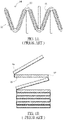
- the ion secondary batteries are the optimal solution. Further, various secondary batteries such as lithium ion secondary batteries, magnesium ion secondary batteries, and sodium ion secondary batteries have been developed. Therefore, how to improve the energy density as much as possible in a limited space has always been the focus of the development of the entire related industry.
- both sides of a single current collector 11 are respectively and repeatedly coated with a cathode active material and an anode active material to form the anode patterns 12 and the cathode patterns 13. Then, non-coating portions of the current collector 11, on which the anode patterns 12 and the cathode patterns 13 are not formed, are bent into a vertical-sectional zigzag shape.
- the separators 14 are disposed at the interfaces of the facing anode patterns 12 and cathode patterns 13 to form the zigzag-shaped battery cell.
- a positive electrode having a plurality of positive patterns formed by being pattern-coated with a positive active material at a predetermined interval and positive uncoated regions where the positive active material is not coated, and a negative electrode having a plurality of negative patterns formed by being pattern-coated with a negative active material at a predetermined interval and negative uncoated regions where the negative active material is not coated are provided.
- a separator disposed between the positive electrode and the negative electrode is formed in a zigzag-shape by bending the positive uncoated region and the negative uncoated region.
- the flexible separator 15 is used to be bent.
- the anode electrode 16 and the cathode electrode 17 are only attached on the separator 15.
- the anode electrode 16 and the cathode electrode 17 are electrically insulated by the separator 15 to perform the vertical stacking.
- the positive active material and the negative active material are bent directly through the separator to form a vertical stacking. Without any buffering mechanism, due to the bending forces it is easy to cause the active materials to be broken. Further, the electrolytes are shared, it will face the problems of the limitation of the maximum permissible voltage and the non-uniform electric field distribution.
- this invention provides an electrode assembly and its battery device thereof to mitigate or obviate the aforementioned problems.
- the electrochemical systems of the electrode assembly are folded to be vertically stacked in a zigzag shape.
- the bending position includes only the belt current collector and the glue frame to prevent the active materials to be broken.
- the electrochemical systems of the electrode assembly are folded to be vertically stacked in a zigzag shape and for the electrical connections. Therefore, the amount of the tabs configured to be connected in series or parallel is reduced.
- the production efficiency and the arrangement for power requirements are improved, and the difficulty in manufacturing processes and the energy density loss caused by space configuration are reduced.
- the electrode assembly is formed by the electrochemical systems and the glue frame to be directly sandwiched between two belt current collectors. Therefore, it is easy to mass produce and to be productized for mass production.
- this invention discloses an electrode assembly, which includes a first belt current collector, a second belt current collector, a glue frame, a plurality of electrochemical systems and a plurality of bending portions.
- the electrochemical systems are disposed between the first belt current collector and the second belt current collector.
- the electrochemical systems are completely sealed by the glue frame, the first belt current collector and the second belt current collector, to make charge transfer occurring between adjacent two of the electrochemical systems without electrochemical reaction.
- the glue frame which are located between any two adjacent electrochemical systems, together with the first belt current collector and the second belt current collector adhered by these portions of the glue frame are folded to form the bending portions.
- the electrochemical systems are vertically stacked repeatedly in a back to front orientation along with a single axis.
- the bending position only includes the glue frame and the belt current collector adhered by the glue frame to prevent the active materials to be broken.
- this invention discloses a battery device.
- a housing is utilized to package the electrode assembly.
- the fire retardant or the coolant is filled between the electrode assembly and the housing to improve heat dissipation efficiency to maintain battery performance and the battery device safety is also enhanced.
- installation means “connected”, and “disposed” are to be understood broadly, and may be fixed or detachable, for example, can be mechanical or electrical, can be connected directly or indirectly, through an intermediate medium, which can be the internal connection between two components.
- intermediate medium which can be the internal connection between two components.
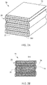
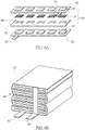
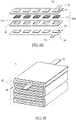
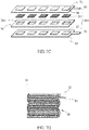
- FIGS. 2A-2D are the schematic diagram, the side view diagram and the exploded diagram before bending of the electrode assembly of this invention.
- the electrode assembly 30 includes a first belt current collector 32, a second belt current collector 33, a plurality of electrochemical systems 301, a glue frame 36, and a plurality of bending portions 38.
- the electrochemical systems 301 and the glue frame 36 are sandwiched between the first belt current collector 32 and the second belt current collector 33.
- the glue frame 36 surrounds all the sides of each electrochemical systems 301.
- the upper surface of the glue frame 36 is adhered to the first belt current collector 32, and the lower surface of the glue frame 36 is adhered to the second belt current collector 33.
- the glue frame 36 includes a plurality of through openings 361.
- Each of the electrochemical systems 301 is accommodated in one of the through openings 361.
- the two surfaces of the electrochemical systems 301 are contacted with the first belt current collector 32 and the second belt current collector 33. Therefore, each of the electrochemical systems 301 is completely sealed by the glue frame 36, and the first belt current collector 32 and the second belt current collector 33.
- Each of electrochemical systems 301 serves as an independent module and the electrochemical systems 301 do not share any components used to compose the electrochemical system 301, such as electrolyte system. That is, only charge transfer occurring through the first belt current collector 32 and the second belt current collector 33, between adjacent two of the electrochemical systems 301 without electrochemical reaction, i.e.
- the glue frame 36 may be a single element with a plurality of through openings 361. Also, there may have a plurality of glue frames 36 with respective through opening 361 thereof, as refer to FIG. 3 .
- the materials of the first belt current collector 32 and the second belt current collector 33 are copper (Cu), Aluminum (Al), or nickel (Ni), tin (Sn), silver (Ag), gold (Au), or an alloy comprised of at least one of the foregoing metals, or polymer materials with high electrical conductivity, such as polymers mixing with electrically conductive materials. Due to the first belt current collector 32 and the second belt current collector 33 are belt-shaped, it is easy to mass produce by patterned coating.
- the electrochemical system 301 includes a first active material layer 34, a second active material layer 35, a separator 31 disposed between the first active material layer 34 and the second active material layer 35 and the electrolyte system impregnated or mixed in the first active material layers 34 and the second active material layers 35.
- any two of the electrochemical systems 301 do not share any components, such as the first active material layers 34, the second active material layers 35, the separators 31 or the electrolyte systems.
- An example embodiment for the manufacturing method is described below.
- the inner side of the first belt current collector 32 is respectively and repeatedly coated with the first active material layers 34 by a predetermined spacing.
- the inner side of the second belt current collector 33 is respectively and repeatedly coated with the second active material layers 35 by the same predetermined spacing.
- Each of the first active material layers 34 is opposed and corresponding to one of the second active material layers 35 respectively.
- Each of the separators 31 is sandwiched between one of the first active material layer 34 and the corresponding second active material layer 35 to form one electrochemical system 301.
- the separator 31 may be a porous lamination formed by polymers or the glass fibers, or the separator 31 may be a ceramic separator, which is stacked or sintered by ceramic materials, with pores to permit ion migrations. The pores are through holes or ant holes, i.e. non-straight through holes.
- the separator 31 may be the porous lamination with a ceramic particles reinforcing layer, or a separator mixing with ceramic particles and ion-conductive polymers.
- the size of the ceramic particles are nanometer scale, micrometer scale or mixing with at least two larger different scale, such as mixing with nanometer scale and micrometer scale.
- the material of the ceramic particles is TiO 2 , Al 2 O 3 , SiO 2 , alkylated ceramic particulates, or an oxide-based solid electrolyte, such as LLZO (lithium lanthanum zirconium oxide, Li 7 La 3 Zr 2 O 12 ) or LATP(Li 1+x Al x Ti 2-x (PO 4 ) 3 ).
- the ceramic material may be mixed with the ceramic insulating materials and the oxide-based solid electrolyte.
- the separator 31, in case of being stacked by ceramic materials, may further include a polymer adhesive used to bind these ceramic particles.
- the polymer adhesive may be polyvinylidene fluoride (PVDF), polyvinylidene fluoride co-hexafluoropropylene (PVDF-HFP), polytetrafluoroethene (PTFE), acrylic acid glue, epoxy resin, polyethylene oxide (PEO), polyacrylonitrile (PAN), and polyimide (PI).
- PVDF polyvinylidene fluoride
- PVDF-HFP polyvinylidene fluoride co-hexafluoropropylene
- PTFE polytetrafluoroethene
- acrylic acid glue epoxy resin
- PEO polyethylene oxide
- PAN polyacrylonitrile
- PI polyimide
- the above-mentioned predetermined spacing of the first active material layer 34 and the second active material layer 35 can be adjusted based on the requirement in practice.
- the widths of the first active material layer 34 and the second active material layer 35 may also be modified.
- the distribution and arrangement of the predetermined spacing, the first active material layers 34 and the second active material layers 35 may be varied.
- the glue frame 36 is disposed to surround the electrochemical systems 301.
- the upper surface of the glue frame 36 is adhered to the first belt current collector 32, and the lower surface of the glue frame 36 is adhered to the second belt current collector 33. Therefore, all the electrochemical systems 301 are completely sealed by the glue frame 36, the first belt current collector 32 and the second belt current collector 33.
- the electrolyte system is impregnated or mixed in first active material layers 34 and the second active material layers 35.
- the electrolyte system is a gel electrolyte, a liquid electrolyte, a solid electrolyte or a combinations thereof. Therefore, by the active materials of first active material layers 34 and the second active material layers 35, the processes that the chemical energy is converted into electrical energy, i.e.
- the glue frame 36 is described below.
- the glue frames 36 are coated on the first belt current collector 32 and the second belt current collector 33 respectively. Then, the first belt current collector 32 and the second belt current collector 33 are adhered to each other by the hot pressing process. Also, the glue frames 36 may be coated only on either the first belt current collector 32 or the second belt current collector 33.
- the materials of the glue frame 36 include the epoxy, polyethylene (PE), polypropylene (PP), polyurethane (PU), thermoplastic polyimide (TPI), silicone, acrylic resin and/or ultraviolet light curing adhesive.
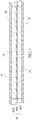
- the glue frames 36 may include two modified silicone layers 362, 363 and a silicone layer 364 disposed between the two modified silicone layers 362, 363, please see FIG. 4 .
- the modified silicone layer 362 is adhered to the first belt current collector 32, and the modified silicone layer 363 is adhered to the second belt current collector 33.
- the silicone layer 364 is sandwiched between the two modified silicone layers 362, 363.
- the modified silicone layers 362, 363 are modified by adjusting a proportion of condensation-type silicone and addition-type silicone comparing to the silicone layer 364, or adding an additive to enhance adhesion for different material, i.e. the material of the first belt current collector 32 or the second belt current collector 33. Therefore, the adhesion between the interfaces of the first belt current collector 32 or the second belt current collector 33 and the glue frame 36 is enhanced. The overall appearance is more complete and the production yield is improved.
- the glue frame 36 which are located between any two adjacent electrochemical systems 301, together with the first belt current collector 32 and the second belt current collector 33 adhered by these portions of the glue frame 36 are folded to form the bending portions 38. Therefore, the electrochemical systems 301 will be vertically stacked relative to the same orientation. Detailed description will be presented in follows.
- the electrochemical systems 301 of the electrode assembly are folded to be vertically stacked in a zigzag shape, please see FIGS. 2A-2B .
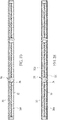
- at least one of the first belt current collector 32 and the second belt current collector 33 includes a structural reinforcing layer 321, 331 on an outer surface to improve a mechanical strength thereon, as shown in FIG. 2E .
- the structural reinforcing layer is made of a material including polyethylene terephthalate (PET), polyvinyl chloride (PVC), polyethylene (PE), polypropylene (PP), polystyrene (PS), polyimide, nylon, polyurethane, acrylic epoxy, silicone or a combinations thereof.
- PET polyethylene terephthalate
- PVC polyvinyl chloride
- PE polyethylene
- PP polypropylene
- PS polystyrene
- polyimide polyimide
- nylon polyurethane
- acrylic epoxy acrylic epoxy
- silicone silicone
- the electrochemical system 301 nearest the edge is folded by the bending portion 38, which is formed by the glue frame 36 near to this electrochemical system 301, together with the first belt current collector 32 and the second belt current collector 33 adhered by the portions of the glue frame 36.
- This electrochemical system 301 nearest the edge is stacked to the next electrochemical system 301, please refer to FIG. 5B .
- the two stacked electrochemical systems 301 are folded in opposite directions by the next bending portion 38.
- this bending portion 38 is formed by the next glue frame 36, together with the first belt current collector 32 and the second belt current collector 33 adhered by the portions of the glue frame 36.
- the electrodes i.e. the first active material layers 34 and the second active material layers 35, would not be affected, such as being broken resulting from the bending or stacking force.
- the stacked electrochemical systems 301 are folded repeatedly in a back to front orientation to form the electrode assembly 30, please see FIGS 5C-5E .
- the electrode assembly with vertical stacking of the electrochemical systems 301 in a zigzag shape is achieved.
- the first belt current collector 32 and the second belt current collector 33 are shared for all the electrochemical systems 301. Therefore, the electrochemical systems 301 in the electrode assembly 30 are connected in parallel.
- first active material layers 34 and the second active material layers 35 would not be affected during bending, thus the damage to the first active material layers 34 and the second active material layers 35 is avoided.
- the first belt current collector 32 and the second belt current collector 33 are usually made of metal materials, which have good malleability.
- the glue frame 36 may be made of a material with better flexibility, such as silicone. The bending process is easier to preform to achieve the electrode assembly 30 with vertical stacking of the electrochemical systems 301 in a zigzag shape.
- the heat dissipating current collectors 41, 42 are adapted to improve heat dissipation.
- the heat dissipating current collectors 41, 42 respectively include the plate body 411, 421 and a plurality of extension plates 412, 422, extended from an edge of the plate body 411, 421.
- the extension plates 412, 422 are disposed between the stacked electrochemical systems 301 and contacts with the first belt current collector 32 and the second belt current collector 33.
- the large-area contact structure can effectively dissipate the heat generated by the electrochemical systems 301 to maintain the best performance of the electrochemical systems 301.
- the heat dissipating current collectors 41, 42 may serve as additional electrically connection outputs.
- the electrode assembly 30 is packaged by a housing to form a battery device, as disclosed in the FIGS. 6A and 6B .
- the housing is an aluminum plastic film 51.
- the first belt current collector 32 and the second belt current collector 33 include the leads 52, 53 respectively to transmit the electricity outside.
- the electrode assembly 30 is composed of an odd number of electrochemical systems 301.
- the leads 52, 53 are extended from the lateral sides of the electrode assembly 30.
- the lateral sides of the electrode assembly 30 are the two longitudinal sides of the electrode assembly 30, or the sides which are perpendicular to the bending direction.
- the leads 52, 53 are located at the same side. Also, please see FIGS.
- the electrode assembly 30 is composed of an even number of electrochemical systems 301, and the leads 52, 53 are located at the different sides.
- the leads 52, 53 may be located at the different sides.
- the leads 52, 53 may be located at the same side.
- the leads 52, 53 may be extended from the ends of electrode assembly 30, i.e. parallel to the bending direction of the electrochemical systems 301.
- the electrode assembly 30 is composed of an odd number of electrochemical systems 301.
- the leads 52, 53 are extended from the two different ends of the electrode assembly 30.
- the leads 52, 53 may be extended from the same end of the electrode assembly 30, as shown in FIGS. 7C and 7D .
- the leads 52, 53 may be extended from the two different ends of the electrode assembly 30.
- the leads 52, 53 may be extended from the same end of the electrode assembly 30.
- the electrode assembly 30 with vertical stacking of the electrochemical systems 301 in a zigzag shape may be composed of an odd or even number of electrochemical systems 301. The production efficiency and the arrangement for power requirements are improved, and the difficulty in manufacturing processes is reduced.
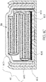
- the housing is a case 61 for quasi-coin batteries.
- the first belt current collector 32 and the second belt current collector 33 of the electrode assembly 30 are contacted with upper and lower inner outputs to form electrical connections.
- the lengths of the electrochemical systems 301 are varied, but are not limited to, based on the profile of the case 61 to make the energy density be maximized. It may be an easier way to mass-produce that the lengths of the electrochemical systems 301 are uniform, as shown in FIG. 4E, or any other arrangements.
- a fire retardant or a coolant is filled between the electrode assembly and the housing, either the aluminum plastic film 51 or the case 61 to improve the performance of the battery device and enhance the safety of the battery device.
- the case 61 includes an upper case 611 and a lower case 612.
- An electrically insulating material 613 is disposed between the upper case 611 and the lower case 612 to make the upper case 611 and the lower case 612 be electrically insulated from one another. Please refer to FIG.
- an electrically insulating layer 614 is coated on parts of the inner surfaces, which are not the upper and lower inner outputs, of the upper case 611 and the lower case 612 to prevent the improper electrical transmission between the upper case 611, the lower case 612 and the first belt current collector 32 and the second belt current collector 33.
- the electrode assembly 30 is composed of an odd number of electrochemical systems 301.
- the electrode assembly 30 is composed of an even number of electrochemical systems 301. Due to the uppermost surface and the lowermost surface of the electrode assembly 30 are the same polarity, a conductive bus 615 is adapted to electrically connect the lower case 612 with the belt current collector with another polarity. An electrically insulating body 616 is utilized to prevent short-circuit occur between the lowermost surface of the electrode assembly 30 and the conductive bus 615.
- the conductive bus 615 may be designed as above-mentioned heat dissipating current collectors. The other arrangement and structure are similar, so that the repeated description is omitted.
- the invention provides an electrode assembly and its battery device thereof.
- the electrode assembly is formed by the electrochemical systems and the glue frame to be directly sandwiched between two belt current collectors. All the electrochemical systems are completely sealed by the glue frame and the two belt current collectors. All components of the electrochemical systems do not share between any two electrochemical systems. Therefore, the electrolyte system only circulates within respective electrochemical systems and do not share between any two electrochemical systems. Only the charge transfer occurs between adjacent two of the electrochemical systems.
- the glue frame which are located between any two adjacent electrochemical systems, together with the first belt current collector and the second belt current collector adhered by these portions of the glue frame are folded to form the bending portions.
- the electrochemical systems are folded to the adjacent electrochemical systems to form a vertical stacking in a zigzag shape. Therefore, it is easy to mass produce and the amount of the tabs configured to be connected in series or parallel is reduced. The energy density loss caused by space configuration are reduced. Also, due to the belt current collectors are belt-shaped, it is easy to mass produce the active material layers and the glue fame by patterned coating.
Landscapes
- Chemical & Material Sciences (AREA)
- Chemical Kinetics & Catalysis (AREA)
- Electrochemistry (AREA)
- General Chemical & Material Sciences (AREA)
- Engineering & Computer Science (AREA)
- Manufacturing & Machinery (AREA)
- Secondary Cells (AREA)
- Inorganic Chemistry (AREA)
- Sealing Battery Cases Or Jackets (AREA)
- Cell Electrode Carriers And Collectors (AREA)
- Cell Separators (AREA)
- Inert Electrodes (AREA)
- Electromechanical Clocks (AREA)
- Battery Mounting, Suspending (AREA)
Applications Claiming Priority (2)
| Application Number | Priority Date | Filing Date | Title |
|---|---|---|---|
| TW110109696 | 2021-03-18 | ||
| TW111100917A TWI796927B (zh) | 2021-03-18 | 2022-01-10 | 電極組件及其電池裝置 |
Publications (3)
| Publication Number | Publication Date |
|---|---|
| EP4075555A2 true EP4075555A2 (de) | 2022-10-19 |
| EP4075555A3 EP4075555A3 (de) | 2023-01-11 |
| EP4075555B1 EP4075555B1 (de) | 2026-05-06 |
Family
ID=80735667
Family Applications (1)
| Application Number | Title | Priority Date | Filing Date |
|---|---|---|---|
| EP22161424.1A Active EP4075555B1 (de) | 2021-03-18 | 2022-03-10 | Elektrodenanordnung und batterievorrichtung dafür |
Country Status (4)
| Country | Link |
|---|---|
| US (1) | US20220302463A1 (de) |
| EP (1) | EP4075555B1 (de) |
| JP (1) | JP7417647B2 (de) |
| KR (1) | KR102754003B1 (de) |
Families Citing this family (3)
| Publication number | Priority date | Publication date | Assignee | Title |
|---|---|---|---|---|
| KR20250036936A (ko) * | 2023-02-27 | 2025-03-14 | 컨템포러리 엠퍼렉스 테크놀로지 (홍콩) 리미티드 | 전극 조립체, 전지 셀, 전지 및 전기 장치 |
| KR102927426B1 (ko) * | 2023-06-01 | 2026-02-12 | 삼성에스디아이 주식회사 | 전극 조립체 및 이를 포함하는 이차 전지 |
| KR20250134812A (ko) * | 2024-03-05 | 2025-09-12 | 삼성에스디아이 주식회사 | 전고체 전지 및 이의 제조방법 |
Citations (3)
| Publication number | Priority date | Publication date | Assignee | Title |
|---|---|---|---|---|
| TW200631218A (en) | 2005-02-18 | 2006-09-01 | Amita Technologies Inc | The arrangement of the interlaced electrodes of an improved battery core and the manufacturing method |
| US20140227583A1 (en) | 2012-11-23 | 2014-08-14 | Lg Chem. Ltd. | Method of preparing electrode assembly and electrode assembly prepared using the method |
| US20200335813A1 (en) | 2017-12-01 | 2020-10-22 | Lg Chem, Ltd. | Electrode Assembly and Battery Including the Same |
Family Cites Families (13)
| Publication number | Priority date | Publication date | Assignee | Title |
|---|---|---|---|---|
| US5498489A (en) * | 1995-04-14 | 1996-03-12 | Dasgupta; Sankar | Rechargeable non-aqueous lithium battery having stacked electrochemical cells |
| US7736799B1 (en) * | 2009-07-17 | 2010-06-15 | Tesla Motors, Inc. | Method and apparatus for maintaining cell wall integrity during thermal runaway using an outer layer of intumescent material |
| JP2011065913A (ja) * | 2009-09-18 | 2011-03-31 | Sumitomo Electric Ind Ltd | 非水固体電解質電池およびその製造方法 |
| JP5599366B2 (ja) * | 2011-05-16 | 2014-10-01 | 日立造船株式会社 | 固体組電池の製造方法 |
| CN103548196B (zh) * | 2011-05-27 | 2016-03-02 | 丰田自动车株式会社 | 双极全固体电池 |
| JPWO2012164723A1 (ja) * | 2011-06-02 | 2014-07-31 | トヨタ自動車株式会社 | 全固体電池の製造方法 |
| WO2013161051A1 (ja) * | 2012-04-27 | 2013-10-31 | 株式会社日本マイクロニクス | 二次電池 |
| JP2015005447A (ja) * | 2013-06-21 | 2015-01-08 | 株式会社豊田自動織機 | 蓄電装置 |
| JP2016110856A (ja) * | 2014-12-08 | 2016-06-20 | シチズンホールディングス株式会社 | 扁平型電池 |
| TWI676315B (zh) * | 2017-10-20 | 2019-11-01 | 輝能科技股份有限公司 | 複合式電池芯 |
| US12046708B2 (en) * | 2017-11-03 | 2024-07-23 | Renata Sa | Foldable flexible assembling of cells for a lithium-ion battery and current collector with carbon based conductive material |
| EP3608997A1 (de) * | 2018-08-08 | 2020-02-12 | Prologium Technology Co., Ltd. | Horizontale zusammengesetzte stromversorgungsstruktur |
| JP7411331B2 (ja) * | 2019-01-11 | 2024-01-11 | 日立造船株式会社 | 全固体電池および全固体電池の製造方法 |
-
2022
- 2022-03-03 US US17/685,633 patent/US20220302463A1/en active Pending
- 2022-03-07 KR KR1020220028851A patent/KR102754003B1/ko active Active
- 2022-03-09 JP JP2022036330A patent/JP7417647B2/ja active Active
- 2022-03-10 EP EP22161424.1A patent/EP4075555B1/de active Active
Patent Citations (3)
| Publication number | Priority date | Publication date | Assignee | Title |
|---|---|---|---|---|
| TW200631218A (en) | 2005-02-18 | 2006-09-01 | Amita Technologies Inc | The arrangement of the interlaced electrodes of an improved battery core and the manufacturing method |
| US20140227583A1 (en) | 2012-11-23 | 2014-08-14 | Lg Chem. Ltd. | Method of preparing electrode assembly and electrode assembly prepared using the method |
| US20200335813A1 (en) | 2017-12-01 | 2020-10-22 | Lg Chem, Ltd. | Electrode Assembly and Battery Including the Same |
Also Published As
| Publication number | Publication date |
|---|---|
| EP4075555B1 (de) | 2026-05-06 |
| KR102754003B1 (ko) | 2025-01-10 |
| KR20220130588A (ko) | 2022-09-27 |
| JP2022145585A (ja) | 2022-10-04 |
| US20220302463A1 (en) | 2022-09-22 |
| JP7417647B2 (ja) | 2024-01-18 |
| EP4075555A3 (de) | 2023-01-11 |
Similar Documents
| Publication | Publication Date | Title |
|---|---|---|
| EP3474341B1 (de) | Zusammengesetzte batteriezelle | |
| EP4075555B1 (de) | Elektrodenanordnung und batterievorrichtung dafür | |
| JP5339407B2 (ja) | 電池パック | |
| TWM615887U (zh) | 類鈕扣電池模組及其電池裝置 | |
| US11978873B2 (en) | Battery module with cooling cartridge and battery system thereof | |
| CN115117367B (zh) | 电极组件及其电池装置 | |
| JP3246636U (ja) | ソフトパックバッテリモジュールおよびその電力サプライ | |
| TWI796927B (zh) | 電極組件及其電池裝置 | |
| KR200499246Y1 (ko) | 방열 리드탭을 구비한 병렬형 배터리 셀 | |
| CN115117522B (zh) | 软包式电池模块及其电能供应器 | |
| CN214848765U (zh) | 具有独立监控的金属壳式电池装置 | |
| CN214754060U (zh) | 类钮扣电池模块及其电池装置 | |
| KR200499830Y1 (ko) | 독립적인 모니터링 기능을 갖는 금속 하우징형 배터리 장치 | |
| CN115117497A (zh) | 具散热匣体的电池模块及其电池系统 |
Legal Events
| Date | Code | Title | Description |
|---|---|---|---|
| PUAI | Public reference made under article 153(3) epc to a published international application that has entered the european phase |
Free format text: ORIGINAL CODE: 0009012 |
|
| STAA | Information on the status of an ep patent application or granted ep patent |
Free format text: STATUS: THE APPLICATION HAS BEEN PUBLISHED |
|
| AK | Designated contracting states |
Kind code of ref document: A2 Designated state(s): AL AT BE BG CH CY CZ DE DK EE ES FI FR GB GR HR HU IE IS IT LI LT LU LV MC MK MT NL NO PL PT RO RS SE SI SK SM TR |
|
| PUAL | Search report despatched |
Free format text: ORIGINAL CODE: 0009013 |
|
| AK | Designated contracting states |
Kind code of ref document: A3 Designated state(s): AL AT BE BG CH CY CZ DE DK EE ES FI FR GB GR HR HU IE IS IT LI LT LU LV MC MK MT NL NO PL PT RO RS SE SI SK SM TR |
|
| RIC1 | Information provided on ipc code assigned before grant |
Ipc: H01M 50/486 20210101ALI20221207BHEP Ipc: H01M 50/474 20210101ALI20221207BHEP Ipc: H01M 50/477 20210101ALI20221207BHEP Ipc: H01M 50/46 20210101ALI20221207BHEP Ipc: H01M 10/654 20140101ALI20221207BHEP Ipc: H01M 10/647 20140101ALI20221207BHEP Ipc: H01M 10/613 20140101ALI20221207BHEP Ipc: H01M 10/04 20060101AFI20221207BHEP |
|
| STAA | Information on the status of an ep patent application or granted ep patent |
Free format text: STATUS: REQUEST FOR EXAMINATION WAS MADE |
|
| 17P | Request for examination filed |
Effective date: 20230706 |
|
| RBV | Designated contracting states (corrected) |
Designated state(s): AL AT BE BG CH CY CZ DE DK EE ES FI FR GB GR HR HU IE IS IT LI LT LU LV MC MK MT NL NO PL PT RO RS SE SI SK SM TR |
|
| GRAP | Despatch of communication of intention to grant a patent |
Free format text: ORIGINAL CODE: EPIDOSNIGR1 |
|
| STAA | Information on the status of an ep patent application or granted ep patent |
Free format text: STATUS: GRANT OF PATENT IS INTENDED |
|
| INTG | Intention to grant announced |
Effective date: 20260120 |
|
| GRAS | Grant fee paid |
Free format text: ORIGINAL CODE: EPIDOSNIGR3 |
|
| GRAA | (expected) grant |
Free format text: ORIGINAL CODE: 0009210 |
|
| STAA | Information on the status of an ep patent application or granted ep patent |
Free format text: STATUS: THE PATENT HAS BEEN GRANTED |