EP4075417B1 - Dispositif et procédé de marquage pérenne d'un objet - Google Patents
Dispositif et procédé de marquage pérenne d'un objet Download PDFInfo
- Publication number
- EP4075417B1 EP4075417B1 EP22166108.5A EP22166108A EP4075417B1 EP 4075417 B1 EP4075417 B1 EP 4075417B1 EP 22166108 A EP22166108 A EP 22166108A EP 4075417 B1 EP4075417 B1 EP 4075417B1
- Authority
- EP
- European Patent Office
- Prior art keywords
- label
- identification device
- frame
- receiving support
- marking
- Prior art date
- Legal status (The legal status is an assumption and is not a legal conclusion. Google has not performed a legal analysis and makes no representation as to the accuracy of the status listed.)
- Active
Links
Images



Classifications
-
- G—PHYSICS
- G09—EDUCATION; CRYPTOGRAPHY; DISPLAY; ADVERTISING; SEALS
- G09F—DISPLAYING; ADVERTISING; SIGNS; LABELS OR NAME-PLATES; SEALS
- G09F21/00—Mobile visual advertising
- G09F21/04—Mobile visual advertising by land vehicles
-
- G—PHYSICS
- G09—EDUCATION; CRYPTOGRAPHY; DISPLAY; ADVERTISING; SEALS
- G09F—DISPLAYING; ADVERTISING; SIGNS; LABELS OR NAME-PLATES; SEALS
- G09F3/00—Labels, tag tickets, or similar identification or indication means; Seals; Postage or like stamps
- G09F3/08—Fastening or securing by means not forming part of the material of the label itself
- G09F3/10—Fastening or securing by means not forming part of the material of the label itself by an adhesive layer
-
- G—PHYSICS
- G09—EDUCATION; CRYPTOGRAPHY; DISPLAY; ADVERTISING; SEALS
- G09F—DISPLAYING; ADVERTISING; SIGNS; LABELS OR NAME-PLATES; SEALS
- G09F3/00—Labels, tag tickets, or similar identification or indication means; Seals; Postage or like stamps
- G09F3/08—Fastening or securing by means not forming part of the material of the label itself
- G09F3/18—Casings, frames or enclosures for labels
-
- G—PHYSICS
- G09—EDUCATION; CRYPTOGRAPHY; DISPLAY; ADVERTISING; SEALS
- G09F—DISPLAYING; ADVERTISING; SIGNS; LABELS OR NAME-PLATES; SEALS
- G09F7/00—Signs, name or number plates, letters, numerals, or symbols; Panels or boards
- G09F7/02—Signs, plates, panels or boards using readily-detachable elements bearing or forming symbols
- G09F7/12—Signs, plates, panels or boards using readily-detachable elements bearing or forming symbols the elements being secured or adapted to be secured by self-adhesion, moisture, suction, slow-drying adhesive or the like
-
- G—PHYSICS
- G09—EDUCATION; CRYPTOGRAPHY; DISPLAY; ADVERTISING; SEALS
- G09F—DISPLAYING; ADVERTISING; SIGNS; LABELS OR NAME-PLATES; SEALS
- G09F7/00—Signs, name or number plates, letters, numerals, or symbols; Panels or boards
- G09F7/16—Letters, numerals, or other symbols adapted for permanent fixing to a support
-
- G—PHYSICS
- G09—EDUCATION; CRYPTOGRAPHY; DISPLAY; ADVERTISING; SEALS
- G09F—DISPLAYING; ADVERTISING; SIGNS; LABELS OR NAME-PLATES; SEALS
- G09F7/00—Signs, name or number plates, letters, numerals, or symbols; Panels or boards
- G09F7/18—Means for attaching signs, plates, panels, or boards to a supporting structure
- G09F2007/1856—Means for attaching signs, plates, panels, or boards to a supporting structure characterised by the supporting structure
- G09F2007/1865—Means for attaching signs, plates, panels, or boards to a supporting structure characterised by the supporting structure on vehicles
Definitions
- the present invention is particularly suitable for marking individual vehicles such as bicycles, scooters, mopeds or motorcycles. It will be described more particularly in its application to the marking of bicycles, by way of non-limiting example.
- WO 2012/101369 A1 a more sophisticated and complex method of marking an object such as a bicycle, using a translucent marking part attached and fixed to the bicycle frame.
- This marking part has a wall which delimits a chamber located between the wall and the surface of the bicycle frame. In this chamber is inserted an identification label.
- the marking part has two openings giving access to the chamber for the injection and circulation of a translucent glue in order to drown the identification label in the volume of injected glue.
- This method represents progress in terms of marking security, since the label is protected behind a wall of the marking part and part of the glue is injected.
- this marking method is much more complex and expensive than previous solutions. It requires the use of consumables such as tubes for injecting glue, which are lost with each use, as well as the excess glue that remains there.
- the marking device also includes several additional parts, in addition to the marking part itself, such as ribs acting as spacers to position the identification label in the chamber, and baffles arranged inside the chamber to ensure the guidance and proper distribution of the injected glue. Due to the complex structure of the parts used, the marking process using this device is relatively long and therefore expensive.
- the general aim of the present invention is in particular to propose an improved marking device and method, intended in particular but not exclusively for the identification of bicycles, and capable of eliminating the drawbacks of known marking systems.
- the invention aims in particular to provide better resistance of the identifier to tearing. It also aims, in the event of tearing after a significant resistance time, for the marking to leave traces of tearing that are very difficult to remove, regardless of the more or less granular or more or less smooth nature of the support. It should be noted that in several countries, the marking of a bicycle can only be legally carried out by professionals, who will hesitate or even give up on reselling a bicycle whose identifier has clearly been torn off.
- Another object of the invention is to propose a device and a method for installing an identifier which is significantly simpler, faster, more reliable and less expensive than known systems. Furthermore, the installation must require very little handling and without requiring any special skills.
- Another aim of the invention is to propose a device having a very simple structure, with a very small number of parts, having a long service life, and using little glue and few or no additional consumables.
- the invention consists in proposing a marking device according to claim 1 consisting of a flexible plastic label previously marked with an identifier, in particular using a laser beam, the label being provided with a frame delimiting a cavity that is filled before fixing the device on its host support, with a resin that can be hardened by polymerization under a UV lamp.
- This hardenable resin is a two-component resin comprising a mixture of a hardenable resin and a hardening agent, leading to an extremely strong bond between the label and the host support.
- the lower face of the frame intended to be fixed on a support to be marked comprises on its rear face a thin protective film (also called a "liner" in English terminology) comprising a cutout corresponding to the surface of the cavity.
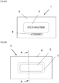
- FIG 1 schematically represents a cross-sectional view of an identification device 1 according to the invention. It essentially comprises a label 2 whose lower face has a frame 3 which extends over the periphery of the label so as to delimit a volume or cavity 5 which is intended to be filled by a layer 4 of glue or resin to ensure a very strong bond with a receiving support 10 (visible in figure 3 ), consisting for example of a portion of a bicycle frame.
- the function of the label 2 is to carry a unique identifier that allows the bicycle or object to be tracked.
- This may include a unique alphanumeric identifier ( ID1234567890 in the example shown), which is also entered into a database for tracking purposes in the event of theft of the marked bicycle or object.
- This identifier may be produced in various ways, depending on the material used for the label, and whether it is opaque or translucent.
- the label 2 is made of polycarbonate (PC), polyethylene (PET), or polyvinyl chloride (PVC).
- PC polycarbonate
- PET polyethylene
- PVC polyvinyl chloride
- polycarbonate is a plastic material having excellent mechanical properties and thermal resistance allowing use between -100°C and 120°C.
- it can be treated to resist ultraviolet radiation so as not to weaken the device when the docking support 10 is left outdoors as in the case of bicycles.
- the identifier can be produced on its upper surface, by printing, or preferably by laser engraving which will reveal the identifier in black.
- the upper face of the label 2 (the front ), shown in Figure 2A , either covered with a protective varnish (not shown).
- the identifier can be produced by printing or laser engraving on the lower face of the label, shown in Figure 2B (the back ), or by laser engraving inside the body of the label, during its manufacture in the factory, therefore before installation on a support to be identified. In both cases no protective varnish will be necessary, the marking of the identifier not being exposed to the effects of the environment after the installation of the label.
- the rear face of the label 2 namely the one opposite the visible front face and accessible after installation, comprises a frame 3 which extends along the periphery of the rear face of the label 2. Its role is to define a volume or a cavity 5 which will be filled with an extremely strong glue which will ensure a very solid connection between the label 2 and a reception support 10, for example a portion of a bicycle frame.
- Cavity 5 of the label is filled with glue or polymerizable resin directly during its manufacture in the factory, and polymerized just after the device is placed on the host support.
- the device it is preferable for the device to have a protective layer opaque to UV rays in order to prevent the glue from polymerizing before the device is placed.
- the frame 3 can be formed by a double-sided adhesive tape, one front face of which will be fixed to the back face of the label 2 and the other face of which will be fixed when the device 1 is placed on the receiving support 10.
- the adhesion of the back face of the frame 3 to the receiving support 10 will make it possible to hold the identification device 1 in place while waiting for the glue or resin 4 to harden.
- the frame 3 can be formed as an integral part of the label 2, for example by molding or 3D printing the plastic material of the label 2.
- the label 2 will for example have a rectangular shape of approximately 60 mm x 20 mm and a thickness of approximately 200 to 300 microns.
- the frame 3 will have a width of 4 to 5 mm and a thickness of 1 to 1.2 mm. It should be noted that the dimensions in the figures are not to scale, the thicknesses being exaggerated for clarity. Of course, the dimensions of the various components can easily be adapted for the production of identification devices intended for objects other than bicycles or equivalent.
- the identification device 1 will further comprise on the rear face of the frame 3 a thin protective film 6, in particular made of Teflon, also called a "liner" in English terminology, fixed using a light adhesive that will allow the protective film 6 to be easily peeled off by hand just before installing the device.
- this protective film 6 will have a thickness of the order of 0.08 to 0.1 mm and will simply protect the adhesive rear face of the frame 3 when filling and smoothing the glue 4 in the cavity 5.
- the protective film 6 will however comprise a cutout corresponding to the entire surface of the cavity 5 so as not to hinder the filling of the cavity 5 with the glue 4.
- the latter may further comprise a smaller self-adhesive secondary label 8, as shown in figures 1 , 2A , 3 And 5 , bearing the same identification number as the main label 2, and intended to be placed under the latter directly on the reception support 10.
- the main label 2 is then preferably transparent or translucent and reveals the small secondary label 8 and its identifier at through the main label 2, which allows for additional verification of the authenticity of the main label 2. Furthermore, the secondary label 8 and its identifier will remain visible even after an attempt to tear off or damage the main label 2.
- identification devices 1 can be aligned and fixed on a board 7 (as shown in figure 4 ), which consists of a sheet of protective film 6, for example in A4 format, on which 10 identification devices 1 have been placed, including 10 labels 2 each with its unique identifier. It will then be sufficient to take the labels 2 individually as needed.
- the two labels 2 and 8 of the same identification device 1 may be located side by side on a board 7, as shown in figure 5 . This arrangement will facilitate the laser inscription of the same identification number on a main label 2 and a neighboring secondary label 8, during the manufacture of the devices.
- the self-adhesive secondary label 8 When installing such an identification device 1, the self-adhesive secondary label 8 will first be removed from the board 7 and placed on the support 10. Then the corresponding main label 2, provided with its glue 4, will be removed and placed over the secondary label 8. The secondary label 8 will therefore be under the main label 2 and its hardened glue 4, which has the advantage of having two identification markings at two different levels.
- the main label 2 is larger and very strong, and it makes it very easy to see its identification number, while protecting the secondary label 8 and its identification number.
- the two identification numbers (which can be chosen to be identical or not) will be seen simultaneously, and if the main label 2 is opaque, the identification number of the secondary label 8 will only be seen after the main label 2 has been torn off or destroyed.
- the glue 4 a two-component hardenable resin of a resin based on methyl methacrylate marketed under the reference KEOL-MA 41 M10, and a hardening agent marketed under the reference KEOL-MA 41 M10 HARDENER.
- the identification device 1 After filling the cavity 5 with this two-component mixture of glue 4 using a suitable gun (typically a mixing gun) and smoothing the glue using a spatula or equivalent, the identification device 1 can be placed against the support 10 and a slight pressure applied to the edges of the identification device 1 at the frame 3 to ensure sufficient adhesion. Then the glue 4 will be dried and polymerized, in particular using an ultraviolet lamp. With the glue indicated, drying will take less than 10 minutes, and the glue will be completely hardened at the latest after 24 hours, ensuring the maximum cohesion sought.
- a suitable gun typically a mixing gun
- the invention achieves the set goals. It makes it possible to propose individualized identification devices obtained at low cost and which can be taken on demand from a board comprising a plurality of labels protected by a protective film, and each label and its frame can then be used in connection with a two-component polymerizable resin using a simple UV lamp.
- the identification device once installed, is very resistant thanks to the choice of two-component hardening resin which becomes very hard and protects the marking itself from external aggression.
- the main label cannot be removed from the surface to be marked without leaving traces, which helps to deter the theft of bicycles thus marked, and also their concealment or resale, particularly by professionals.
- the identification device according to the invention is particularly simple to install using a very small installation kit that does not require excess glue or additional consumables such as injection tubes or spacers.
- the installation process is very simple and very quick (less than 2 minutes), it requires only a few manipulations, in particular no glue injection phase into a chamber, and the preparation steps such as dispensing resin into the cavity can be done on a table or workbench, and not on the bicycle itself.
Landscapes
- Physics & Mathematics (AREA)
- General Physics & Mathematics (AREA)
- Engineering & Computer Science (AREA)
- Theoretical Computer Science (AREA)
- Business, Economics & Management (AREA)
- Accounting & Taxation (AREA)
- Marketing (AREA)
- Labeling Devices (AREA)
- Lining Or Joining Of Plastics Or The Like (AREA)
- Injection Moulding Of Plastics Or The Like (AREA)
- Vehicle Waterproofing, Decoration, And Sanitation Devices (AREA)
Description
- La présente invention concerne un nouveau dispositif et un nouveau procédé de marquage pérenne d'objets meubles ou mobiles susceptibles d'être exposés à des actions de vol ou de recel.
- La présente invention est particulièrement adaptée au marquage de véhicules individuels tels que les bicyclettes, trottinettes, scooters ou motos. Elle sera décrite plus particulièrement dans son application au marquage des vélos, à titre d'exemple non limitatif.
- On connaît déjà plusieurs procédés pour marquer des objets, notamment des bicyclettes.
- Pendant de nombreuses années, une étiquette en aluminium était frappée d'un numéro d'identification à l'aide d'un poinçon, puis l'étiquette ainsi marquée était fixée au cadre du vélo à l'aide de pattes de fixation entourant un tube du cadre et reliées entre elles par un écrou ou équivalent. Il va de soi qu'une telle étiquette était extrêmement simple à enlever à l'aide d'une simple pince coupante, et le vélo se retrouvait alors dépourvu de tout marquage et de toute trace de vol.
- Devant le nombre croissant de vols d'objets mobiles de valeur tels que des vélos, des perfectionnements aux méthodes de marquage ont été progressivement proposés.
- Ainsi on a commencé par coller des étiquettes de marquage directement sur le cadre du vélo, mais ces étiquettes pouvaient être décollées ou dégradées assez facilement par grattage. On a ensuite cherché à graver un numéro d'identification directement sur le cadre d'un vélo à marquer, notamment à l'aide d'une technique de micro-percussion, mais là encore, ces marquages peuvent être assez facilement enlevés ou dégradés par ponçage à l'aide d'un produit abrasif. En outre ce procédé de marquage nécessite l'investissement dans des machines de micro-percussion, et de plus il n'est pas adapté à des cadres revêtus d'une peinture fragile, ou à des cadres haut de gamme en titane ou en carbone qui sont justement ceux qui ont le plus besoin d'un marquage de sécurité efficace.
- Il a ensuite été proposé par le document
WO 2012/101369 A1 un procédé plus sophistiqué et plus complexe de marquage d'un objet tel qu'un vélo, faisant appel à une pièce de marquage translucide rapportée et fixée sur le cadre du vélo. Cette pièce de marquage présente une paroi qui délimite une chambre située entre la paroi et la surface du cadre du vélo. Dans cette chambre est insérée une étiquette d'identification. En outre, la pièce de marquage comporte deux ouvertures donnant accès à la chambre pour l'injection et la circulation d'une colle translucide afin de noyer l'étiquette d'identification dans le volume de colle injecté. - Ce procédé représente un progrès du point de vue de la sécurité du marquage, l'étiquette étant protégée derrière une paroi de la pièce de marquage et une partie de la colle injectée. En revanche, ce procédé de marquage est bien plus complexe et coûteux que les solutions antérieures. Il nécessite l'utilisation de consommables tels que des tubes pour l'injection de colle, qui sont perdus à chaque utilisation, ainsi que la colle en excès qui y reste. Le dispositif de marquage comporte en outre plusieurs pièces rapportées, en plus de la pièce de marquage proprement dite, telles que des nervures faisant office d'entretoises pour positionner l'étiquette d'identification dans la chambre, et des chicanes disposées à l'intérieur de la chambre afin de s'assurer du guidage et de la bonne répartition de la colle injectée. En raison de la structure complexe des pièces mises en oeuvre, le procédé de marquage utilisant ce dispositif est relativement long et donc coûteux.
- La présente invention a notamment pour but général de proposer un dispositif et un procédé améliorés de marquage, destiné en particulier mais pas exclusivement à l'identification des bicyclettes, et capable de supprimer les inconvénients des systèmes de marquage connus.
- L'invention vise en particulier à offrir une meilleure résistance de l'identifiant à l'arrachement. Elle vise en outre, au cas où un arrachement aurait lieu au bout d'un temps de résistance significatif, à ce que le marquage laisse des traces d'arrachement très difficiles à enlever, quelle que soit la nature plus ou moins granuleuse ou plus ou moins lisse du support. Il faut savoir en effet que dans plusieurs pays, le marquage d'une bicyclette ne peut être légalement effectué que par des professionnels, qui hésiteront voire renonceront à revendre une bicyclette dont l'identifiant aura visiblement été arraché.
- Un autre but de l'invention est de proposer un dispositif et un procédé de pose d'un identifiant qui soit nettement plus simple, plus rapide, plus fiable et moins coûteux que les systèmes connus. En outre la pose doit nécessiter très peu de manipulations et sans faire appel à des compétences particulières.
- Un autre but de l'invention est de proposer un dispositif ayant une structure très simple, avec un nombre très réduit de pièces, présentant une longue durée de vie, et utilisant peu de colle et peu ou pas de consommables annexes.
- Dans son principe, l'invention consiste à proposer un dispositif de marquage selon la revendication 1 constitué par une étiquette en matière plastique souple préalablement marquée avec un identifiant, notamment à l'aide d'un faisceau laser, l'étiquette étant pourvue d'un cadre délimitant une cavité que l'on remplit avant la fixation du dispositif sur son support d'accueil, avec une résine durcissable par polymérisation sous lampe UV. Cette résine durcissable est une résine bi-composant comportant un mélange d'une résine durcissable et d'un agent durcisseur, conduisant à une liaison extrêmement forte entre l'étiquette et le support d'accueil. En outre, la face inférieure du cadre destinée à être fixée sur un support à marquer comporte sur sa face arrière une fine pellicule de protection (encore appelée « liner » en terminologie anglo-saxonne) comportant une découpe correspondant à la surface de la cavité.
- Différents modes de réalisation de l'invention sont exposés dans le jeu de revendications joint.
- L'invention sera décrite plus en détail en rapport avec les figures ci-jointes, dans lesquelles :
- La
figure 1 représente une vue en coupe transversale A-A d'un dispositif de marquage selon l'invention, avant sa pose sur un support à marquer ; - Les
figures 2A et 2B représentent respectivement une vue schématique de dessus et de dessous du dispositif de marquage de lafigure 1 ; - La
figure 3 représente une vue schématique en coupe transversale d'un dispositif de marquage selon l'invention, après sa pose sur un support à marquer ; - La
figure 4 représente une planche de dispositifs d'identification selon l'invention avant leur pose sur un support à marquer ; - La
figure 5 représente une variante de planche de dispositifs d'identification à double étiquette selon l'invention avant leur pose sur un support à marquer. - On se réfère à la
figure 1 qui représente de façon schématique une vue en coupe transversale d'un dispositif d'identification 1 selon l'invention. Il comporte essentiellement une étiquette 2 dont la face inférieure présente un cadre 3 qui s'étend sur la périphérie de l'étiquette de façon à délimiter un volume ou cavité 5 qui est destinée à être remplie par une couche 4 de colle ou résine pour assurer une liaison très forte avec un support d'accueil 10 (visible enfigure 3 ), constitué par exemple par une portion d'un cadre de vélo. - La fonction de l'étiquette 2 est de porter un identifiant unique qui permet le traçage du vélo ou de l'objet. Il peut s'agir notamment d'un identifiant alphanumérique unique ( ID1234567890 dans l'exemple représenté), qui est par ailleurs saisi dans une base de données à des fins de suivi en cas de vol du vélo ou de l'objet marqué. Cet identifiant peut être réalisé de diverses manières, en fonction du matériau utilisé pour l'étiquette, et de son caractère opaque ou translucide.
- Dans un mode de réalisation avantageux, l'étiquette 2 est en polycarbonate (PC), en polyéthylène (PET), ou en polychlorure de vinyle (PVC). En particulier, le polycarbonate est une matière plastique disposant d'excellentes propriétés mécaniques et d'une résistance thermique permettant une utilisation entre -100 °C et 120 °C. En outre il peut être traité pour résister au rayonnement ultraviolet afin de ne pas fragiliser le dispositif lorsque le support d'accueil 10 est laissé en extérieur comme dans le cas des vélos.
- Lorsque l'étiquette 2 est opaque, notamment en polycarbonate blanc ou gris, l'identifiant peut être réalisé sur sa surface supérieure, par impression, ou de préférence par gravure laser qui laissera apparaître l'identifiant en noir. Dans ce mode de réalisation, il pourra être utile que la face supérieure de l'étiquette 2 (le recto), représentée en
figure 2A , soit recouverte d'un vernis de protection (non représenté). Lorsque l'étiquette 2 est choisie translucide ou transparente, l'identifiant peut être réalisé par impression ou gravure laser sur la face inférieure de l'étiquette, représentée enfigure 2B (le verso), ou par gravure laser à l'intérieur du corps de l'étiquette, lors de sa fabrication en usine, donc avant la pose sur un support à identifier. Dans les deux cas aucun verni de protection ne sera nécessaire, le marquage de l'identifiant n'étant pas exposé aux effets de l'environnement après la pose de l'étiquette. - Selon une caractéristique importante du dispositif d'identification 1 selon l'invention, la face arrière de l'étiquette 2, à savoir celle qui est opposée à la face avant visible et accessible après la pose, comporte un cadre 3 qui s'étend le long de la périphérie de la face arrière de l'étiquette 2. Son rôle est de définir un volume ou une cavité 5 que l'on viendra remplir avec une colle extrêmement forte qui assurera une liaison très solide entre l'étiquette 2 et un support d'accueil 10, par exemple une portion d'un cadre de vélo.
- La cavité 5 de l'étiquette est remplie de colle ou de résine polymérisable directement lors de sa fabrication en usine, et polymérisée juste après la pose du dispositif sur le support d'accueil. Dans ce cas il est préférable que le dispositif comporte une couche de protection opaque aux rayons UV afin d'éviter que la colle ne polymérise avant la pose du dispositif.
- Selon un mode de réalisation simple, le cadre 3 peut être formé par un ruban adhésif double-face dont une face avant sera fixée sur la face arrière de l'étiquette 2 et dont l'autre face sera fixée lors de la pose du dispositif 1 sur le support d'accueil 10. L'adhésion de la face arrière du cadre 3 sur le support d'accueil 10 permettra de maintenir le dispositif d'identification 1 en place en attendant que la colle ou résine 4 durcisse.
- Selon un autre mode de réalisation, le cadre 3 peut être formé comme une partie intégrante de l'étiquette 2, par exemple par moulage ou par impression 3D de la matière plastique de l'étiquette 2.
- Dans l'application visée d'identification des vélos, l'étiquette 2 aura par exemple une forme rectangulaire d'environ 60 mm x 20 mm et une épaisseur d'environ 200 à 300 microns. Et le cadre 3 aura une largeur de 4 à 5 mm et une épaisseur de 1 à 1,2 mm. Il est à noter que les dimensions dans les figures ne sont pas à l'échelle, les épaisseurs étant exagérées pour plus de clarté. Bien entendu, les dimensions des différents composants pourront aisément être adaptées pour la réalisation de dispositifs d'identification destinés à d'autres objets que des vélos ou équivalent.
- Selon l'invention, le dispositif d'identification 1 comportera en outre sur la face arrière du cadre 3 une fine pellicule de protection 6, notamment en téflon, encore appelé « liner » en terminologie anglo-saxonne, fixée à l'aide d'un collage léger qui permettra de décoller la pellicule de protection 6 facilement à la main juste avant la pose du dispositif. En outre, cette pellicule de protection 6 aura une épaisseur de l'ordre de 0,08 à 0,1 mm et permettra simplement de protéger la face arrière adhésive du cadre 3 lors du remplissage et du lissage de la colle 4 dans la cavité 5. La pellicule de protection 6 comportera par contre une découpe correspondant à toute la surface de la cavité 5 de façon à ne pas gêner le remplissage de la cavité 5 avec la colle 4.
- Selon une variante encore plus sûre du dispositif d'identification 1, celui-ci peut en outre comprendre une étiquette secondaire 8 autocollante plus petite, comme représenté en
figures 1 ,2A ,3 et5 , portant le même numéro d'identification que l'étiquette principale 2, et destinée à être posée sous celle-ci directement sur le support d'accueil 10. L'étiquette principale 2 est alors de préférence transparente ou translucide et laisse apparaître la petite étiquette secondaire 8 et son identifiant à travers l'étiquette principale 2, ce qui permet une vérification supplémentaire du caractère authentique de l'étiquette principale 2. Par ailleurs, l'étiquette secondaire 8 et son identifiant resteront visibles même après une tentative d'arrachage ou de dégradation de l'étiquette principale 2. - Selon un mode de réalisation avantageux, plusieurs dispositifs d'identification 1 pourront être alignés et fixés sur une planche 7 (comme représenté en
figure 4 ), qui est constituée par une feuille de pellicule de protection 6, par exemple au format A4, sur laquelle on a posé 10 dispositifs d'identification 1, y compris 10 étiquettes 2 avec chacune son identifiant unique. Il suffira alors de prélever les étiquettes 2 à l'unité en fonction des besoins. - Dans le cas d'un dispositif d'identification 1 pourvu d'une étiquette principale 2 et d'une étiquette secondaire 8, les deux étiquettes 2 et 8 d'un même dispositif d'identification 1 pourront être localisées côte à côte sur une planche 7, comme représenté en
figure 5 . Cette disposition facilitera l'inscription par laser du même numéro d'identification sur une étiquette principale 2 et une étiquette secondaire 8 voisine, lors de la fabrication des dispositifs. - Lors de la pose d'un tel dispositif d'identification 1, on prélèvera alors d'abord de la planche 7 l'étiquette secondaire 8 autocollante, et on la posera sur le support d'accueil 10. Puis on prélèvera l'étiquette principale 2 correspondante, pourvue de sa colle 4, et on la posera par-dessus l'étiquette secondaire 8. L'étiquette secondaire 8 se trouvera donc sous l'étiquette principale 2 et sa colle 4 durcie, ce qui présente l'avantage d'avoir deux marquages d'identification à deux niveaux différents. L'étiquette principale 2 est de plus grande taille et très résistante, et elle permet de voir très facilement son numéro d'identification, tout en protégeant l'étiquette secondaire 8 et son numéro d'identification.
- Si l'étiquette principale 2 est transparente on verra simultanément les deux numéros d'identification (qui pourront être choisis identiques ou non), et si l'étiquette principale 2 est opaque, on ne verra le numéro d'identification de l'étiquette secondaire 8 qu'après arrachage ou destruction de l'étiquette principale 2.
- En ce qui concerne la colle 4 destinée à assurer une liaison très forte entre l'étiquette 2 et le support d'accueil 10, on utilisera une résine durcissable bi-composant permettant d'obtenir une soudure chimique très forte, rendant quasi impossible l'arrachement de l'étiquette 2, et qui en tout état de cause laissera des traces indélébiles sur le support d'accueil 10 même après arrachement.
- Selon un mode de réalisation testé avec succès, on pourra utiliser pour la colle 4 une résine durcissable bi-composant d'une résine à base de méthacrylate de méthyle commercialisée sous la référence KEOL-MA 41 M10, et d'un agent durcisseur commercialisé sous la référence KEOL-MA 41 M10 DURCISSEUR.
- Après remplissage de la cavité 5 avec ce mélange bi-composant de colle 4 à l'aide d'un pistolet approprié (typiquement un pistolet mélangeur) et un lissage de la colle à l'aide d'une spatule ou équivalent, on pourra poser le dispositif d'identification 1 contre le support d'accueil 10 et exercer une légère pression sur les bords du dispositif d'identification 1 au niveau du cadre 3 pour assurer une adhésion suffisante. Puis on procédera au séchage et à la polymérisation de la colle 4, notamment au moyen d'une lampe à ultraviolet. Avec la colle indiquée, le séchage prendra moins de 10 minutes, et la colle sera totalement durcie au plus tard au bout de 24 heures, assurant la cohésion maximale recherchée.
- Le procédé de pose d'un dispositif d'identification 1 sur un support d'accueil 10 sera alors le suivant.
- On commencera par nettoyer le support d'accueil 10 avec un produit dégraissant, comme connu en soi, afin que l'adhésion du dispositif d'identification 1 puisse réaliser tout son potentiel.
- On présentera un dispositif d'identification 1 avec sa cavité 5 apparente, et on la remplira avec une dose de colle 4 bi-composant durcissable. On lissera si nécessaire la colle à l'aide d'une spatule de lissage afin que la cavité 5 soit bien remplie, sans excès. L'étape de remplissage manuel de colle pourra être évitée si le remplissage de colle est fait directement sur la chaîne de fabrication des dispositifs d'identification 1 selon l'invention.
- Puis on enlèvera la pellicule de protection 6 afin de présenter la zone adhésive du cadre 3.
- On présentera la face encollée du dispositif d'identification 1 et la zone adhésive du cadre 3 en face du support d'accueil 10, et on l'appliquera à l'endroit prévu, avec une légère pression sur la périphérie pour garantir que la colle 4 reste bien contenue dans la cavité 5 alors que débute sa polymérisation.
- Enfin on séchera ou polymérisera la colle 4, par exemple à l'aide d'une lampe UV.
- L'invention atteint les buts fixés. Elle permet de proposer des dispositifs d'identification individualisés obtenus à faible coût et que l'on peut prélever à la demande à partir d'une planche comportant une pluralité d'étiquettes protégées par une pellicule de protection, et on peut alors utiliser chaque étiquette et son cadre en liaison avec une résine polymérisable bi-composant à l'aide d'une simple lampe UV.
- Le dispositif d'identification une fois posé est très résistant grâce au choix de la résine durcissable bi-composant qui devient très dure et qui protège le marquage proprement dit des agressions extérieures.
- L'étiquette principale ne peut pas être enlevée du support à marquer sans laisser de traces, ce qui permet de dissuader le vol de bicyclettes ainsi marquées, et aussi leur recel ou revente, en particulier par des professionnels.
- Le dispositif d'identification selon l'invention est particulièrement simple à poser à l'aide d'un kit de pose très réduit qui ne nécessite pas d'excès de colle, ni de consommables rapportés comme des tubes d'injection ou des entretoises. Le procédé de pose est très simple et très rapide (moins de 2 minutes), il ne nécessite que peu de manipulations, en particulier pas de phase d'injection de colle dans une chambre, et les étapes de préparation comme la dispense de résine dans la cavité peuvent être faites sur une table ou un établi, et non pas sur le vélo lui-même.
Claims (10)
- Dispositif d'identification (1) destiné à être fixé sur un objet présentant un support d'accueil (10), comportant une étiquette (2) en matière plastique pourvue d'une face supérieure présentant un identifiant visible et une face inférieure destinée à être fixée sur ledit support d'accueil, la face inférieure du dispositif d'identification (1) comportant un cadre (3) faisant partie intégrante de la face inférieure de l'étiquette (2) et réalisé avec le même matériau que l'étiquette (2), et comportant sur sa face inférieure une couche adhésive permettant son collage sur le support d'accueil (10), et ledit cadre (3) épousant le pourtour de l'étiquette (2) de façon à délimiter une cavité (5), caractérisé en ce que ladite cavité (5) est remplie avant la fixation du dispositif d'identification (1) sur le support d'accueil par une résine durcissable par polymérisation sous lampe UV constituée par une résine bi-composant comportant un mélange d'une résine durcissable et d'un agent durcisseur, et en ce que ledit cadre (3) comporte sur sa face arrière une fine pellicule de protection (6) comportant une découpe correspondant à la surface de la cavité (5).
- Dispositif d'identification (1) selon la revendication 1, caractérisé en ce que ledit cadre (3) est une pièce rapportée, en matière plastique ou en film adhésif, collée d'une part sur la face inférieure de l'étiquette (2) et d'autre part sur le support d'accueil (10).
- Dispositif d'identification (1) selon l'une quelconque des revendications précédentes, caractérisé en ce que ladite étiquette (2) est en polycarbonate ou en PET.
- Dispositif d'identification (1) selon l'une quelconque des revendications précédentes, caractérisé en ce que l'étiquette (2) est opaque et en ce que l'identifiant est un marquage réalisé sur la surface supérieure de l'étiquette (2) par laser ou par impression.
- Dispositif d'identification (1) selon l'une quelconque des revendications 1 à 4, caractérisé en ce que l'étiquette (2) est translucide et en ce que l'identifiant est un marquage réalisé au laser dans l'épaisseur du corps de l'étiquette (2) ou sur sa face inférieure.
- Dispositif d'identification (1) selon l'une quelconque des revendications précédentes, adapté pour l'identification d'objets mobiles tels que des bicyclettes, caractérisé en ce que l'étiquette (2) a une forme sensiblement rectangulaire d'environ 20 mm x 60 mm et une épaisseur d'environ 250 micromètres, et le cadre (3) a la forme d'une bande présentant une largeur d'environ 4 à 6 mm et une épaisseur de 1 à 1,2 mm.
- Dispositif d'identification (1) selon l'une quelconque des revendications précédentes, caractérisé en ce qu'il comporte une étiquette principale (2), et une étiquette secondaire (8) destinée à être disposée entre le support d'accueil (10) et l'étiquette principale (2).
- Dispositif d'identification (1) selon la revendication 7, caractérisé en ce que le liner (6) a la forme d'une planche (7) portant une pluralité de dispositifs d'identification (1) et pourvu d'une découpe en face de la cavité (5) de chaque dispositif d'identification (1).
- Procédé de marquage d'un objet à l'aide d'un dispositif d'identification (1) selon les revendications 1 à 6, caractérisé en ce qu'il comporte des étapes consistant à :- Marquer une étiquette (2) avec un identifiant sur une face ou dans la matière de l'étiquette (2) ;- Nettoyer la surface du support d'accueil (10) de l'objet destiné à recevoir le dispositif d'identification (1) ;- Remplir le volume de la cavité (5) de l'étiquette (2) délimitée par le cadre (3) avec un mélange de résine bi-composant polymérisable ;- Décoller l'étiquette (2) et son cadre (3) rempli de résine de sa pellicule de protection (6) ;- Reporter l'étiquette (2) et le cadre (3) rempli de résine sur le support d'accueil (10) de l'objet à marquer ;- Polymériser à l'aide d'une lampe UV la résine bi-composant de façon à la durcir et ainsi solidariser l'étiquette (2) et le support d'accueil (10).10
- Procédé de marquage d'un objet à l'aide d'un dispositif d'identification (1) selon la revendication 7, caractérisé en ce qu'il comporte des étapes consistant à :- Marquer une étiquette principale (2) et une étiquette secondaire (8) avec un identifiant sur une face ou dans la matière desdites étiquettes (2 ; 8) ;- Nettoyer la surface du support d'accueil (10) de l'objet destiné à recevoir le dispositif d'identification (1) ;- Décoller l'étiquette secondaire (8) de sa pellicule de protection (6) et la coller sur le support d'accueil (10) ;- Remplir le volume de la cavité (5) de l'étiquette principale (2) délimitée par le cadre (3) avec un mélange de résine bi-composant polymérisable ;- Décoller l'étiquette principale (2) de sa pellicule de protection (6) ;- Reporter l'étiquette principale (2) avec son cadre (3) rempli de résine sur le support d'accueil (10) de l'objet à marquer, au-dessus de l'étiquette secondaire (8) ;- Polymériser à l'aide d'une lampe UV la résine bi-composant de façon à la durcir et ainsi solidariser l'étiquette principale (2) et le support d'accueil (10).
Applications Claiming Priority (1)
| Application Number | Priority Date | Filing Date | Title |
|---|---|---|---|
| FR2103937A FR3122021B1 (fr) | 2021-04-16 | 2021-04-16 | Dispositif et procédé de marquage pérenne d’un objet |
Publications (2)
| Publication Number | Publication Date |
|---|---|
| EP4075417A1 EP4075417A1 (fr) | 2022-10-19 |
| EP4075417B1 true EP4075417B1 (fr) | 2025-01-29 |
Family
ID=76283960
Family Applications (1)
| Application Number | Title | Priority Date | Filing Date |
|---|---|---|---|
| EP22166108.5A Active EP4075417B1 (fr) | 2021-04-16 | 2022-03-31 | Dispositif et procédé de marquage pérenne d'un objet |
Country Status (2)
| Country | Link |
|---|---|
| EP (1) | EP4075417B1 (fr) |
| FR (1) | FR3122021B1 (fr) |
Family Cites Families (2)
| Publication number | Priority date | Publication date | Assignee | Title |
|---|---|---|---|---|
| US20050230960A1 (en) * | 2004-03-29 | 2005-10-20 | Bilodeau Wayne L | Security label, secured article and method for making the label and article |
| FR2970804B1 (fr) | 2011-01-24 | 2013-02-22 | Alexandre Francois | Procede de marquage d'un objet |
-
2021
- 2021-04-16 FR FR2103937A patent/FR3122021B1/fr active Active
-
2022
- 2022-03-31 EP EP22166108.5A patent/EP4075417B1/fr active Active
Also Published As
| Publication number | Publication date |
|---|---|
| FR3122021B1 (fr) | 2023-12-29 |
| FR3122021A1 (fr) | 2022-10-21 |
| EP4075417A1 (fr) | 2022-10-19 |
Similar Documents
| Publication | Publication Date | Title |
|---|---|---|
| JP4827846B2 (ja) | 転写フィルムおよび加飾射出成形品並びにその製造方法 | |
| CN102202906B (zh) | 涂覆的塑料基板的部件标记 | |
| FR2662267A1 (fr) | Element en feuille reflechissant colore et son procede de fabrication. | |
| FR2955327A1 (fr) | Film en matiere plastique mono-oriente pour la fabrication d'un manchon thermoretractable dechirable, et manchon realise a partir d'un tel film | |
| CA2819428C (fr) | Procede de fabrication d'un article permettant l'apposition d'un film decoratif sur un support definitif | |
| EP4075417A1 (fr) | Dispositif et procédé de marquage pérenne d'un objet | |
| EP1165328A1 (fr) | Dispositif d'equilibrage pour roue et roue equilibree par collage d'un tel dispositif d'equilibrage | |
| EP2668647B1 (fr) | Procede de marquage d'un objet | |
| EP3287195B1 (fr) | Kit de masquage à positionnement optimisé et procédé associé | |
| FR2716559A1 (fr) | Plaquette pour des opérations de marquage, de certification et/ou de contrôle. | |
| FR2789656A1 (fr) | Caisse a claire voie sur laquelle est collee une etiquette imprimee pelliculable | |
| JP2004230571A (ja) | ホログラムラベル及びその製造方法 | |
| JP2003177672A (ja) | シュリンクラベル及びその製造方法 | |
| EP2230480B1 (fr) | Article de traçage avec graduation et/ou motifs imprimés | |
| EP0841709A1 (fr) | Etiquette de protection et décoration notamment pour pile électrique | |
| WO2008012353A1 (fr) | Rubans souples de transfert d'energie a aimantation, et procede pour leur fabrication | |
| EP1240021B1 (fr) | Manchon comportant des moyens de fixation de plaques d'impression et procede d'obtention | |
| FR2706664A1 (fr) | Procédé de réalisation de panneaux signalétiques & enseignes publicitaires. | |
| JP4463575B2 (ja) | 複写防止媒体及び複写防止媒体用ラベル | |
| FR2834484A1 (fr) | Procede de realisation d'un dispositif de protection a film de securite transferable et transparent aux ultraviolets courts | |
| FR2876110A1 (fr) | Ruban transparent pour plaques photopolymeres | |
| FR2680903A1 (fr) | Dispositif de dissuasion de vol pour marquer de maniere indelebile et identifier un materiel. | |
| FR3111843A1 (fr) | Procédés de fabrication de composants optiques de sécurité, composants optiques de sécurité et objets sécurisés équipés de tels composants | |
| FR2598538A1 (fr) | Procede d'identification antivol d'un objet et etiquettes antivol a apposer sur un objet | |
| FR2776236A1 (fr) | Transfert a sec a froid, procede de fabrication et procede d'application |
Legal Events
| Date | Code | Title | Description |
|---|---|---|---|
| PUAI | Public reference made under article 153(3) epc to a published international application that has entered the european phase |
Free format text: ORIGINAL CODE: 0009012 |
|
| STAA | Information on the status of an ep patent application or granted ep patent |
Free format text: STATUS: THE APPLICATION HAS BEEN PUBLISHED |
|
| STAA | Information on the status of an ep patent application or granted ep patent |
Free format text: STATUS: REQUEST FOR EXAMINATION WAS MADE |
|
| AK | Designated contracting states |
Kind code of ref document: A1 Designated state(s): AL AT BE BG CH CY CZ DE DK EE ES FI FR GB GR HR HU IE IS IT LI LT LU LV MC MK MT NL NO PL PT RO RS SE SI SK SM TR |
|
| 17P | Request for examination filed |
Effective date: 20220930 |
|
| RBV | Designated contracting states (corrected) |
Designated state(s): AL AT BE BG CH CY CZ DE DK EE ES FI FR GB GR HR HU IE IS IT LI LT LU LV MC MK MT NL NO PL PT RO RS SE SI SK SM TR |
|
| STAA | Information on the status of an ep patent application or granted ep patent |
Free format text: STATUS: EXAMINATION IS IN PROGRESS |
|
| 17Q | First examination report despatched |
Effective date: 20230629 |
|
| GRAP | Despatch of communication of intention to grant a patent |
Free format text: ORIGINAL CODE: EPIDOSNIGR1 |
|
| STAA | Information on the status of an ep patent application or granted ep patent |
Free format text: STATUS: GRANT OF PATENT IS INTENDED |
|
| RIC1 | Information provided on ipc code assigned before grant |
Ipc: G09F 7/18 20060101ALN20240829BHEP Ipc: G09F 7/12 20060101ALI20240829BHEP Ipc: G09F 7/16 20060101ALI20240829BHEP Ipc: G09F 3/10 20060101ALI20240829BHEP Ipc: G09F 3/18 20060101ALI20240829BHEP Ipc: G09F 21/04 20060101AFI20240829BHEP |
|
| RIC1 | Information provided on ipc code assigned before grant |
Ipc: G09F 7/18 20060101ALN20240902BHEP Ipc: G09F 7/12 20060101ALI20240902BHEP Ipc: G09F 7/16 20060101ALI20240902BHEP Ipc: G09F 3/10 20060101ALI20240902BHEP Ipc: G09F 3/18 20060101ALI20240902BHEP Ipc: G09F 21/04 20060101AFI20240902BHEP |
|
| RIC1 | Information provided on ipc code assigned before grant |
Ipc: G09F 7/18 20060101ALN20240910BHEP Ipc: G09F 7/12 20060101ALI20240910BHEP Ipc: G09F 7/16 20060101ALI20240910BHEP Ipc: G09F 3/10 20060101ALI20240910BHEP Ipc: G09F 3/18 20060101ALI20240910BHEP Ipc: G09F 21/04 20060101AFI20240910BHEP |
|
| INTG | Intention to grant announced |
Effective date: 20240919 |
|
| GRAJ | Information related to disapproval of communication of intention to grant by the applicant or resumption of examination proceedings by the epo deleted |
Free format text: ORIGINAL CODE: EPIDOSDIGR1 |
|
| GRAP | Despatch of communication of intention to grant a patent |
Free format text: ORIGINAL CODE: EPIDOSNIGR1 |
|
| GRAS | Grant fee paid |
Free format text: ORIGINAL CODE: EPIDOSNIGR3 |
|
| INTG | Intention to grant announced |
Effective date: 20241120 |
|
| GRAA | (expected) grant |
Free format text: ORIGINAL CODE: 0009210 |
|
| STAA | Information on the status of an ep patent application or granted ep patent |
Free format text: STATUS: THE PATENT HAS BEEN GRANTED |
|
| AK | Designated contracting states |
Kind code of ref document: B1 Designated state(s): AL AT BE BG CH CY CZ DE DK EE ES FI FR GB GR HR HU IE IS IT LI LT LU LV MC MK MT NL NO PL PT RO RS SE SI SK SM TR |
|
| REG | Reference to a national code |
Ref country code: GB Ref legal event code: FG4D Free format text: NOT ENGLISH |
|
| REG | Reference to a national code |
Ref country code: CH Ref legal event code: EP |
|
| REG | Reference to a national code |
Ref country code: DE Ref legal event code: R096 Ref document number: 602022009938 Country of ref document: DE |
|
| REG | Reference to a national code |
Ref country code: IE Ref legal event code: FG4D Free format text: LANGUAGE OF EP DOCUMENT: FRENCH |
|
| REG | Reference to a national code |
Ref country code: NL Ref legal event code: MP Effective date: 20250129 |
|
| PG25 | Lapsed in a contracting state [announced via postgrant information from national office to epo] |
Ref country code: NL Free format text: LAPSE BECAUSE OF FAILURE TO SUBMIT A TRANSLATION OF THE DESCRIPTION OR TO PAY THE FEE WITHIN THE PRESCRIBED TIME-LIMIT Effective date: 20250129 |
|
| PG25 | Lapsed in a contracting state [announced via postgrant information from national office to epo] |
Ref country code: RS Free format text: LAPSE BECAUSE OF FAILURE TO SUBMIT A TRANSLATION OF THE DESCRIPTION OR TO PAY THE FEE WITHIN THE PRESCRIBED TIME-LIMIT Effective date: 20250429 |
|
| PG25 | Lapsed in a contracting state [announced via postgrant information from national office to epo] |
Ref country code: FI Free format text: LAPSE BECAUSE OF FAILURE TO SUBMIT A TRANSLATION OF THE DESCRIPTION OR TO PAY THE FEE WITHIN THE PRESCRIBED TIME-LIMIT Effective date: 20250129 |
|
| PG25 | Lapsed in a contracting state [announced via postgrant information from national office to epo] |
Ref country code: PL Free format text: LAPSE BECAUSE OF FAILURE TO SUBMIT A TRANSLATION OF THE DESCRIPTION OR TO PAY THE FEE WITHIN THE PRESCRIBED TIME-LIMIT Effective date: 20250129 |
|
| PG25 | Lapsed in a contracting state [announced via postgrant information from national office to epo] |
Ref country code: ES Free format text: LAPSE BECAUSE OF FAILURE TO SUBMIT A TRANSLATION OF THE DESCRIPTION OR TO PAY THE FEE WITHIN THE PRESCRIBED TIME-LIMIT Effective date: 20250129 |
|
| REG | Reference to a national code |
Ref country code: LT Ref legal event code: MG9D |
|
| PG25 | Lapsed in a contracting state [announced via postgrant information from national office to epo] |
Ref country code: NO Free format text: LAPSE BECAUSE OF FAILURE TO SUBMIT A TRANSLATION OF THE DESCRIPTION OR TO PAY THE FEE WITHIN THE PRESCRIBED TIME-LIMIT Effective date: 20250429 Ref country code: IS Free format text: LAPSE BECAUSE OF FAILURE TO SUBMIT A TRANSLATION OF THE DESCRIPTION OR TO PAY THE FEE WITHIN THE PRESCRIBED TIME-LIMIT Effective date: 20250529 |
|
| REG | Reference to a national code |
Ref country code: AT Ref legal event code: MK05 Ref document number: 1764263 Country of ref document: AT Kind code of ref document: T Effective date: 20250129 |
|
| PG25 | Lapsed in a contracting state [announced via postgrant information from national office to epo] |
Ref country code: HR Free format text: LAPSE BECAUSE OF FAILURE TO SUBMIT A TRANSLATION OF THE DESCRIPTION OR TO PAY THE FEE WITHIN THE PRESCRIBED TIME-LIMIT Effective date: 20250129 |
|
| PG25 | Lapsed in a contracting state [announced via postgrant information from national office to epo] |
Ref country code: LV Free format text: LAPSE BECAUSE OF FAILURE TO SUBMIT A TRANSLATION OF THE DESCRIPTION OR TO PAY THE FEE WITHIN THE PRESCRIBED TIME-LIMIT Effective date: 20250129 Ref country code: PT Free format text: LAPSE BECAUSE OF FAILURE TO SUBMIT A TRANSLATION OF THE DESCRIPTION OR TO PAY THE FEE WITHIN THE PRESCRIBED TIME-LIMIT Effective date: 20250529 |
|
| PG25 | Lapsed in a contracting state [announced via postgrant information from national office to epo] |
Ref country code: GR Free format text: LAPSE BECAUSE OF FAILURE TO SUBMIT A TRANSLATION OF THE DESCRIPTION OR TO PAY THE FEE WITHIN THE PRESCRIBED TIME-LIMIT Effective date: 20250430 Ref country code: BG Free format text: LAPSE BECAUSE OF FAILURE TO SUBMIT A TRANSLATION OF THE DESCRIPTION OR TO PAY THE FEE WITHIN THE PRESCRIBED TIME-LIMIT Effective date: 20250129 |
|
| PG25 | Lapsed in a contracting state [announced via postgrant information from national office to epo] |
Ref country code: AT Free format text: LAPSE BECAUSE OF FAILURE TO SUBMIT A TRANSLATION OF THE DESCRIPTION OR TO PAY THE FEE WITHIN THE PRESCRIBED TIME-LIMIT Effective date: 20250129 |
|
| PG25 | Lapsed in a contracting state [announced via postgrant information from national office to epo] |
Ref country code: SE Free format text: LAPSE BECAUSE OF FAILURE TO SUBMIT A TRANSLATION OF THE DESCRIPTION OR TO PAY THE FEE WITHIN THE PRESCRIBED TIME-LIMIT Effective date: 20250129 |
|
| PG25 | Lapsed in a contracting state [announced via postgrant information from national office to epo] |
Ref country code: SM Free format text: LAPSE BECAUSE OF FAILURE TO SUBMIT A TRANSLATION OF THE DESCRIPTION OR TO PAY THE FEE WITHIN THE PRESCRIBED TIME-LIMIT Effective date: 20250129 |
|
| PG25 | Lapsed in a contracting state [announced via postgrant information from national office to epo] |
Ref country code: DK Free format text: LAPSE BECAUSE OF FAILURE TO SUBMIT A TRANSLATION OF THE DESCRIPTION OR TO PAY THE FEE WITHIN THE PRESCRIBED TIME-LIMIT Effective date: 20250129 |
|
| PG25 | Lapsed in a contracting state [announced via postgrant information from national office to epo] |
Ref country code: MC Free format text: LAPSE BECAUSE OF FAILURE TO SUBMIT A TRANSLATION OF THE DESCRIPTION OR TO PAY THE FEE WITHIN THE PRESCRIBED TIME-LIMIT Effective date: 20250129 |
|
| PG25 | Lapsed in a contracting state [announced via postgrant information from national office to epo] |
Ref country code: IT Free format text: LAPSE BECAUSE OF FAILURE TO SUBMIT A TRANSLATION OF THE DESCRIPTION OR TO PAY THE FEE WITHIN THE PRESCRIBED TIME-LIMIT Effective date: 20250129 |
|
| PG25 | Lapsed in a contracting state [announced via postgrant information from national office to epo] |
Ref country code: CZ Free format text: LAPSE BECAUSE OF FAILURE TO SUBMIT A TRANSLATION OF THE DESCRIPTION OR TO PAY THE FEE WITHIN THE PRESCRIBED TIME-LIMIT Effective date: 20250129 Ref country code: EE Free format text: LAPSE BECAUSE OF FAILURE TO SUBMIT A TRANSLATION OF THE DESCRIPTION OR TO PAY THE FEE WITHIN THE PRESCRIBED TIME-LIMIT Effective date: 20250129 |
|
| REG | Reference to a national code |
Ref country code: CH Ref legal event code: H13 Free format text: ST27 STATUS EVENT CODE: U-0-0-H10-H13 (AS PROVIDED BY THE NATIONAL OFFICE) Effective date: 20251023 |
|
| PG25 | Lapsed in a contracting state [announced via postgrant information from national office to epo] |
Ref country code: RO Free format text: LAPSE BECAUSE OF FAILURE TO SUBMIT A TRANSLATION OF THE DESCRIPTION OR TO PAY THE FEE WITHIN THE PRESCRIBED TIME-LIMIT Effective date: 20250129 |
|
| PG25 | Lapsed in a contracting state [announced via postgrant information from national office to epo] |
Ref country code: SK Free format text: LAPSE BECAUSE OF FAILURE TO SUBMIT A TRANSLATION OF THE DESCRIPTION OR TO PAY THE FEE WITHIN THE PRESCRIBED TIME-LIMIT Effective date: 20250129 |
|
| REG | Reference to a national code |
Ref country code: DE Ref legal event code: R097 Ref document number: 602022009938 Country of ref document: DE |
|
| PG25 | Lapsed in a contracting state [announced via postgrant information from national office to epo] |
Ref country code: LU Free format text: LAPSE BECAUSE OF NON-PAYMENT OF DUE FEES Effective date: 20250331 |
|
| PLBE | No opposition filed within time limit |
Free format text: ORIGINAL CODE: 0009261 |
|
| STAA | Information on the status of an ep patent application or granted ep patent |
Free format text: STATUS: NO OPPOSITION FILED WITHIN TIME LIMIT |
|
| REG | Reference to a national code |
Ref country code: BE Ref legal event code: MM Effective date: 20250331 |
|
| 26N | No opposition filed |
Effective date: 20251030 |
|
| PG25 | Lapsed in a contracting state [announced via postgrant information from national office to epo] |
Ref country code: BE Free format text: LAPSE BECAUSE OF NON-PAYMENT OF DUE FEES Effective date: 20250331 |
|
| PG25 | Lapsed in a contracting state [announced via postgrant information from national office to epo] |
Ref country code: CH Free format text: LAPSE BECAUSE OF NON-PAYMENT OF DUE FEES Effective date: 20250331 |
|
| PG25 | Lapsed in a contracting state [announced via postgrant information from national office to epo] |
Ref country code: IE Free format text: LAPSE BECAUSE OF NON-PAYMENT OF DUE FEES Effective date: 20250331 |
|
| PGFP | Annual fee paid to national office [announced via postgrant information from national office to epo] |
Ref country code: GB Payment date: 20260324 Year of fee payment: 5 |
|
| PGFP | Annual fee paid to national office [announced via postgrant information from national office to epo] |
Ref country code: DE Payment date: 20260319 Year of fee payment: 5 |
|
| PGFP | Annual fee paid to national office [announced via postgrant information from national office to epo] |
Ref country code: FR Payment date: 20260323 Year of fee payment: 5 |