EP4075111B1 - Heizgerät mit einer optischen sensoranordnung an einem fenster zum verbrennungsraum - Google Patents
Heizgerät mit einer optischen sensoranordnung an einem fenster zum verbrennungsraum Download PDFInfo
- Publication number
- EP4075111B1 EP4075111B1 EP22166638.1A EP22166638A EP4075111B1 EP 4075111 B1 EP4075111 B1 EP 4075111B1 EP 22166638 A EP22166638 A EP 22166638A EP 4075111 B1 EP4075111 B1 EP 4075111B1
- Authority
- EP
- European Patent Office
- Prior art keywords
- sensor
- window
- tube
- heating device
- region
- Prior art date
- Legal status (The legal status is an assumption and is not a legal conclusion. Google has not performed a legal analysis and makes no representation as to the accuracy of the status listed.)
- Active
Links
Images

Classifications
-
- G—PHYSICS
- G01—MEASURING; TESTING
- G01J—MEASUREMENT OF INTENSITY, VELOCITY, SPECTRAL CONTENT, POLARISATION, PHASE OR PULSE CHARACTERISTICS OF INFRARED, VISIBLE OR ULTRAVIOLET LIGHT; COLORIMETRY; RADIATION PYROMETRY
- G01J5/00—Radiation pyrometry, e.g. infrared or optical thermometry
- G01J5/0014—Radiation pyrometry, e.g. infrared or optical thermometry for sensing the radiation from gases, flames
- G01J5/0018—Flames, plasma or welding
-
- F—MECHANICAL ENGINEERING; LIGHTING; HEATING; WEAPONS; BLASTING
- F23—COMBUSTION APPARATUS; COMBUSTION PROCESSES
- F23D—BURNERS
- F23D14/00—Burners for combustion of a gas, e.g. of a gas stored under pressure as a liquid
- F23D14/02—Premix gas burners, i.e. in which gaseous fuel is mixed with combustion air upstream of the combustion zone
-
- F—MECHANICAL ENGINEERING; LIGHTING; HEATING; WEAPONS; BLASTING
- F23—COMBUSTION APPARATUS; COMBUSTION PROCESSES
- F23M—CASINGS, LININGS, WALLS OR DOORS SPECIALLY ADAPTED FOR COMBUSTION CHAMBERS, e.g. FIREBRIDGES; DEVICES FOR DEFLECTING AIR, FLAMES OR COMBUSTION PRODUCTS IN COMBUSTION CHAMBERS; SAFETY ARRANGEMENTS SPECIALLY ADAPTED FOR COMBUSTION APPARATUS; DETAILS OF COMBUSTION CHAMBERS, NOT OTHERWISE PROVIDED FOR
- F23M11/00—Safety arrangements
- F23M11/04—Means for supervising combustion, e.g. windows
- F23M11/042—Viewing ports of windows
-
- F—MECHANICAL ENGINEERING; LIGHTING; HEATING; WEAPONS; BLASTING
- F23—COMBUSTION APPARATUS; COMBUSTION PROCESSES
- F23M—CASINGS, LININGS, WALLS OR DOORS SPECIALLY ADAPTED FOR COMBUSTION CHAMBERS, e.g. FIREBRIDGES; DEVICES FOR DEFLECTING AIR, FLAMES OR COMBUSTION PRODUCTS IN COMBUSTION CHAMBERS; SAFETY ARRANGEMENTS SPECIALLY ADAPTED FOR COMBUSTION APPARATUS; DETAILS OF COMBUSTION CHAMBERS, NOT OTHERWISE PROVIDED FOR
- F23M11/00—Safety arrangements
- F23M11/04—Means for supervising combustion, e.g. windows
- F23M11/045—Means for supervising combustion, e.g. windows by observing the flame
-
- F—MECHANICAL ENGINEERING; LIGHTING; HEATING; WEAPONS; BLASTING
- F23—COMBUSTION APPARATUS; COMBUSTION PROCESSES
- F23N—REGULATING OR CONTROLLING COMBUSTION
- F23N5/00—Systems for controlling combustion
- F23N5/02—Systems for controlling combustion using devices responsive to thermal changes or to thermal expansion of a medium
- F23N5/08—Systems for controlling combustion using devices responsive to thermal changes or to thermal expansion of a medium using light-sensitive elements
- F23N5/082—Systems for controlling combustion using devices responsive to thermal changes or to thermal expansion of a medium using light-sensitive elements using electronic means
-
- G—PHYSICS
- G01—MEASURING; TESTING
- G01J—MEASUREMENT OF INTENSITY, VELOCITY, SPECTRAL CONTENT, POLARISATION, PHASE OR PULSE CHARACTERISTICS OF INFRARED, VISIBLE OR ULTRAVIOLET LIGHT; COLORIMETRY; RADIATION PYROMETRY
- G01J1/00—Photometry, e.g. photographic exposure meter
- G01J1/02—Details
- G01J1/04—Optical or mechanical part supplementary adjustable parts
- G01J1/0407—Optical elements not provided otherwise, e.g. manifolds, windows, holograms, gratings
- G01J1/0466—Optical elements not provided otherwise, e.g. manifolds, windows, holograms, gratings with a sighting port
-
- G—PHYSICS
- G01—MEASURING; TESTING
- G01J—MEASUREMENT OF INTENSITY, VELOCITY, SPECTRAL CONTENT, POLARISATION, PHASE OR PULSE CHARACTERISTICS OF INFRARED, VISIBLE OR ULTRAVIOLET LIGHT; COLORIMETRY; RADIATION PYROMETRY
- G01J1/00—Photometry, e.g. photographic exposure meter
- G01J1/42—Photometry, e.g. photographic exposure meter using electric radiation detectors
- G01J1/429—Photometry, e.g. photographic exposure meter using electric radiation detectors applied to measurement of ultraviolet light
-
- G—PHYSICS
- G01—MEASURING; TESTING
- G01J—MEASUREMENT OF INTENSITY, VELOCITY, SPECTRAL CONTENT, POLARISATION, PHASE OR PULSE CHARACTERISTICS OF INFRARED, VISIBLE OR ULTRAVIOLET LIGHT; COLORIMETRY; RADIATION PYROMETRY
- G01J5/00—Radiation pyrometry, e.g. infrared or optical thermometry
- G01J5/02—Constructional details
- G01J5/0205—Mechanical elements; Supports for optical elements
-
- G—PHYSICS
- G01—MEASURING; TESTING
- G01J—MEASUREMENT OF INTENSITY, VELOCITY, SPECTRAL CONTENT, POLARISATION, PHASE OR PULSE CHARACTERISTICS OF INFRARED, VISIBLE OR ULTRAVIOLET LIGHT; COLORIMETRY; RADIATION PYROMETRY
- G01J5/00—Radiation pyrometry, e.g. infrared or optical thermometry
- G01J5/02—Constructional details
- G01J5/08—Optical arrangements
- G01J5/0875—Windows; Arrangements for fastening thereof
-
- G—PHYSICS
- G01—MEASURING; TESTING
- G01N—INVESTIGATING OR ANALYSING MATERIALS BY DETERMINING THEIR CHEMICAL OR PHYSICAL PROPERTIES
- G01N21/00—Investigating or analysing materials by the use of optical means, i.e. using sub-millimetre waves, infrared, visible or ultraviolet light
- G01N21/62—Systems in which the material investigated is excited whereby it emits light or causes a change in wavelength of the incident light
- G01N21/71—Systems in which the material investigated is excited whereby it emits light or causes a change in wavelength of the incident light thermally excited
- G01N21/72—Systems in which the material investigated is excited whereby it emits light or causes a change in wavelength of the incident light thermally excited using flame burners
-
- F—MECHANICAL ENGINEERING; LIGHTING; HEATING; WEAPONS; BLASTING
- F23—COMBUSTION APPARATUS; COMBUSTION PROCESSES
- F23C—METHODS OR APPARATUS FOR COMBUSTION USING FLUID FUEL OR SOLID FUEL SUSPENDED IN A CARRIER GAS OR AIR
- F23C2900/00—Special features of, or arrangements for combustion apparatus using fluid fuels or solid fuels suspended in air; Combustion processes therefor
- F23C2900/9901—Combustion process using hydrogen, hydrogen peroxide water or brown gas as fuel
-
- F—MECHANICAL ENGINEERING; LIGHTING; HEATING; WEAPONS; BLASTING
- F23—COMBUSTION APPARATUS; COMBUSTION PROCESSES
- F23N—REGULATING OR CONTROLLING COMBUSTION
- F23N2241/00—Applications
- F23N2241/06—Space-heating and heating water
-
- F—MECHANICAL ENGINEERING; LIGHTING; HEATING; WEAPONS; BLASTING
- F23—COMBUSTION APPARATUS; COMBUSTION PROCESSES
- F23N—REGULATING OR CONTROLLING COMBUSTION
- F23N2900/00—Special features of, or arrangements for controlling combustion
- F23N2900/05004—Details of components, e.g. connecting adaptors
-
- F—MECHANICAL ENGINEERING; LIGHTING; HEATING; WEAPONS; BLASTING
- F23—COMBUSTION APPARATUS; COMBUSTION PROCESSES
- F23N—REGULATING OR CONTROLLING COMBUSTION
- F23N2900/00—Special features of, or arrangements for controlling combustion
- F23N2900/05005—Mounting arrangements for sensing, detecting or measuring devices
Definitions
- the invention relates to a heating device with an arrangement of an optical sensor on a window (sight glass) to a combustion chamber of a heating device, in particular for the combustion of hydrogen-containing fuel gas, preferably with a hydrogen content of more than 10%, in particular more than 50%, very preferably more than 97%.
- Hydrogen as a fuel gas or as an additive to fuel gases is becoming increasingly important, and great efforts are being made to upgrade new or existing heating devices for operation with it.
- Hydrogen differs in several respects from previously used fuel gases when it is burned (with ambient air).
- a hydrogen flame is almost invisible to the human eye, radiates less heat than flames generated with carbon-containing fuels, and hydrogen flames require different measuring systems to monitor them than other fuels.
- ionization measurements do not provide reliable signals when the fuel gas contains high proportions of hydrogen.
- the present invention is therefore particularly, but not only, applicable to heating devices that are operated with pure hydrogen or with fuel gas that contains proportions of hydrogen.
- optical sensors for the visible, but especially for the ultraviolet range of light
- optical filters for flame monitoring and combustion control using optical filters
- the EN 10 2013 111 876 A1 discloses a flame sensor device and a cable assembly device for use in sensing characteristics of a flame in a combustion chamber of an oil or gas fired turbine.
- the flame sensor device can be arranged on a sight tube positioned in front of an opening of the combustion chamber.
- the flame sensor device further comprises a cable assembly with various seals provided to prevent moisture, gas and contaminants from passing through the cable assembly opening.
- the EN 10 2014 108 290 A1 relates to an optical monitoring system for a gas turbine engine.
- This comprises an optical connection device with a first axial end and a second axial end, the first axial end being optically coupled to a viewing window of a combustion chamber and arranged to receive the image from the viewing window.
- the optical connection device has a substrate with a plurality of hollow channels, each of which extends from the first axial end to the second axial end, and each hollow channel contains a reflective coating arranged on an inner surface of the hollow channel to enable the transmission of a corresponding part of the image. This is intended to emitted electromagnetic radiation can be fed to a detector arrangement with sufficient intensity and negligible interference.
- the optical sensor system is aligned with the flame in the combustion chamber using a simple bracket so that the sensor system can measure this flame.
- the bracket only has to meet structural requirements.
- the light must be able to escape from the combustion chamber in order to be optically detected.
- a window is incorporated into a housing of the combustion chamber, in particular in a burner door next to a burner. This allows the optical sensor to detect the light from the combustion.
- the object of the present invention is to at least partially solve the problems mentioned with reference to the prior art.
- a heating device with a sensor arrangement for observing flames in a combustion chamber is to be created, which is largely protected against contamination, whereby the sensor receives sufficient light for reliable flame observation and can nevertheless be reliably kept at an operating temperature that is permissible for it.
- Heating devices with an arrangement of an optical sensor according to the independent claims are used to solve this problem.
- Advantageous embodiments and further developments of the invention are specified in the dependent claims.
- a protective component namely the tube, is placed around the optical beam path.
- a tube is in particular a piece of pipe (hollow cylinder) with mechanically stable walls, whereby in this case a round cross-section is not necessarily required.
- the window can be part of the combustion chamber of the heater, for example in the form of a pane that lets through radiation or light.
- the distance between the sensor and the window avoids direct (heat-conducting) contact between the two components.
- the distance can be 2 cm to 20 cm, preferably 5 to 15 cm [centimeters].
- the tube can extend over a gap between the sensor and the window and/or delimit this (radially) on the outside.
- the tube prefferably in (direct) contact with the window and/or the sensor. It is possible for the tube to form or at least partially delimit at least one radiation channel through which the optical radiation passes or is guided. It is possible for several tubes to be provided, and these can be arranged axially and/or radially offset from one another.
- the tube is (essentially) sealed against the window with one inlet end, for example due to circumferential and/or direct contact. This means that no or less dirt can accumulate on the window, which increases the service life (or the time between maintenance of the sensors). Sealing can be achieved either by a (heat-resistant) seal or by a very small gap (also in the form of a labyrinth seal) of e.g. 0.1 to 2 mm [millimeters]. This should ensure that thermal expansion of the components involved is not hindered.
- the sensor is arranged in an outlet end of the tube, i.e. it is carried by or in the tube. This allows the sensor to be positioned exactly in a desired position relative to the window and/or the tube without any other mounting, and only the tube is mounted externally.
- the sensor and the window allow the tube to be sealed practically airtight at both ends, which prevents the ingress of dust and other contamination is reduced or prevented.
- the tube is particularly preferably held in or on an air intake line using a tube holder. Every heating device that uses fuel gas and air has an air intake line, which often runs (or can run) in the area where the sensor is or can be located. Since the air intake line has approximately the same temperature as the ambient air, it is particularly suitable for holding a tube with a sensor.
- the tube can be surrounded by air at least in a partial area.
- the tube runs essentially across the air intake line, which also provides a simple way of holding the tube. No special sealing is required because it does not matter where exactly the intake line takes in air. It just needs to have a sufficient cross-section so that air flows around the tube but does not impede the intake.
- the tube can also have cooling structures in the form of a heat sink.
- the tube is at least in a region close to the sensor and is connected to the sensor in a heat-conducting manner.
- a "good" heat-conducting region is present in particular when the material has a thermal conductivity (at 20°C) of at least 40 W/(mK).
- a metal is particularly suitable as a material for the region close to the sensor.
- plastics that conduct heat well can also be used. Since the window can be at a relatively high temperature when the heater is in operation, it is further provided that the tube is at least in a region close to the window a poor heat conductor. Ceramic materials or Consider heat-resistant plastics (which should also bond well with materials used for other parts of the tube).
- Modern materials which can be produced in particular with 3D printers, also allow a design according to the invention according to a second aspect, in which the tube conducts heat better in the radial direction than in the axial direction.
- the tube hardly conducts any heat from the window to the sensor, but it does conduct heat from the sensor to the environment or the air being sucked in.
- the tube is constructed, at least in parts, from alternating circular disks made of a material with a higher and lower thermal conductivity, for example alternating ceramic and metal.
- the thermal conductivity of the materials differs by at least a factor of 10, in particular by at least a factor of 100.
- the tube can meet the window at an angle that deviates from the vertical by 5° to 30°. This allows larger flame areas to be observed and/or the space available on the outside of the burner flap to be used more effectively.
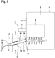
- Fig.1 shows a schematic of a combustion chamber 2 of a heater 1, which is surrounded by a housing 3.
- a burner door 4 or flap
- This burner 5 is supplied with a mixture of air and hydrogen or hydrogen-containing fuel gas via a mixture feed line 6.
- flames 7 are created that are almost invisible to the human eye, at least when pure hydrogen is used as the fuel gas. Nevertheless, these flames 7 emit optical radiation, in particular e.g. in the ultraviolet spectral range, which can be observed by means of a sensor 9.
- the sensor 9 Due to the high temperatures in a combustion chamber 2, the sensor 9 is usually arranged outside in front of a window 8 (sight glass), which is permeable to the optical radiation to be observed. Since the window 8 and its surroundings can also be at a very high temperature, the sensor 9 is arranged at a certain distance A, e.g. 2 cm to 20 cm, preferably 5 to 15 cm, from the window 8. The further the sensor 9 is from the flames 7, the more sensitive it must be in order to be able to fulfil its function, e.g. as a flame monitor or to regulate combustion, since the optical radiation arriving at the sensor 9 is the distance A decreases. Since the sensitivity cannot be increased arbitrarily, small distances A of a few centimeters from the window 8 are usually required.
- the sensor 9 is therefore often cooled with air, in particular with air that is sucked in to form the mixture to be burned.
- the sensor 9 can therefore be arranged in or near an air intake line 12 so that it remains in a permissible temperature range of, for example, below 70° C.
- a tube 11 is arranged between window 8 and sensor 9 through which the optical radiation to be observed passes.
- the tube 11 has a length that essentially corresponds to the distance A or is slightly longer depending on the type of attachment of the sensor 9.
- the tube can rest against the window 8 at an inlet end 16, preferably with a (temperature-resistant) seal 14, or can be separated from the window 8 by a small gap.
- the sensor 9 and its supply lines 10 are held in a sensor holder 13 at or in an outlet end 17 of the tube 11.
- the tube 11 itself is preferably attached to or in an air intake line 12 in a tube holder 15 and is surrounded by air, which, however, cannot get into its interior and therefore cannot contaminate optical surfaces of the sensor 9 or the window 8.
- the tube 11 can be inclined by an angle W relative to a perpendicular S to the surface of the window 8, e.g. by 5 to 30°, preferably 10 to 20°.
- the inlet end 16 is then bevelled accordingly.
- Fig. 2 shows an enlarged section of Fig.1 with the tube 11 in longitudinal axial section. Since the tube 11 does not transfer heat from the window 8 to the sensor 9 by heat conduction, but should contribute to cooling the sensor 9,
- the tube 11 is made up of a region 19 near the sensor that conducts heat well (e.g. made of metal) and a region 20 near the window that conducts heat poorly (or at least worse) (e.g. made of ceramic).
- the region 19 near the sensor optionally also includes a partial region 18 that runs in an air intake line 12 and is cooled by it. In this way, the sensor 9 is also cooled and not heated up by the window 8.
- Fig. 3 shows a special embodiment in which the tube 11 is constructed in such a way that it has a higher thermal conductivity, at least partially radially, than axially.
- This can be achieved, for example, by a structure made up of ring disks 21, 22 that alternately conduct heat well (metallic) and poorly (ceramic).
- Such metallic ring disks 21 and ceramic ring disks 22 can be produced, for example, using 3D printing in the form of a tube 11. They are particularly suitable if the tube 11 is not cooled by an air flow, but is only intended to release heat from the sensor 9 to the outside, without conducting heat from the window 8 to the sensor 9.
- the present invention allows an optical sensor 9 to be attached to a window 8 to a combustion chamber in a manner appropriate to its sensitivity, while simultaneously avoiding contamination of the window 8 and/or sensor 9 and while maintaining a permissible temperature range of the sensor 9.
Landscapes
- Engineering & Computer Science (AREA)
- Physics & Mathematics (AREA)
- General Physics & Mathematics (AREA)
- Chemical & Material Sciences (AREA)
- Spectroscopy & Molecular Physics (AREA)
- Combustion & Propulsion (AREA)
- Mechanical Engineering (AREA)
- General Engineering & Computer Science (AREA)
- Health & Medical Sciences (AREA)
- Nuclear Medicine, Radiotherapy & Molecular Imaging (AREA)
- Life Sciences & Earth Sciences (AREA)
- Analytical Chemistry (AREA)
- Biochemistry (AREA)
- General Health & Medical Sciences (AREA)
- Immunology (AREA)
- Pathology (AREA)
- Plasma & Fusion (AREA)
- Photometry And Measurement Of Optical Pulse Characteristics (AREA)
- Control Of Combustion (AREA)
Description
- Die Erfindung betrifft Heizgerät mit einer Anordnung eines optischen Sensors an einem Fenster (Schauglas) zu einem Verbrennungsraum eines Heizgerätes, insbesondere zur Verbrennung von Wasserstoff enthaltendem Brenngas, bevorzugt mit einem Wasserstoffanteil größer 10%, insbesondere größer 50%, ganz bevorzugt größer 97%. Wasserstoff als Brenngas oder als Beimischung zu Brenngasen wird immer wichtiger, und es werden große Anstrengungen unternommen, neue oder auch existierende Heizgeräte für einen Betrieb damit zu ertüchtigen.
- Dabei geht es nicht nur um große Anlagen, sondern auch um Wandgeräte zur Erwärmung von Wasser und generell um Heizgeräte für die Beheizung von Gebäuden und/oder die Bereitstellung von warmem Wasser. Wasserstoff unterscheidet sich bei seiner Verbrennung (mit Umgebungsluft) in mehreren Punkten von bisher verwendeten Brenngasen, insbesondere ist eine Wasserstofflamme für das menschliche Auge fast unsichtbar, strahlt weniger Wärme ab als mit kohlenstoffhaltigen Brennstoffen erzeugte Flammen, und Wasserstoffflammen benötigen zu ihrer Überwachung andere Messsysteme als andere Brennstoffe. Insbesondere liefern lonisationsmessungen keine zuverlässigen Signale bei hohen Anteilen von Wasserstoff im Brenngas. Die vorliegende Erfindung ist daher besonders, aber nicht nur anwendbar für Heizgeräte, die mit reinem Wasserstoff oder mit Brenngas, das Anteile an Wasserstoff enthält, betrieben werden.
- Eine Verwendung von optischen Sensoren (für den sichtbaren, aber insbesondere auch für den Ultraviolett-Bereich des Lichtes) zur Flammenüberwachung und Regelung der Verbrennung unter Benutzung von optischen Filtern ist für Anwendungen bei Heizgeräten, die mit wasserstoffhaltigem Brenngas betrieben werden, schon beispielsweise aus der
DE 10 2019 101 329 A1 bekannt. Auch dieEP 2 223 016 B1 , dieUS 5 829 962 A und dieDE19 509 704 A1 beschäftigen sich ausführlich mit optischen Messsystemen für die Flammenüberwachung. - Die
DE 10 2013 111 876 A1 offenbart eine Flammensensorvorrichtung und eine Kabelanordnungsvorrichtung zur Verwendung beim Erfassen von Eigenschaften einer Flamme in einer Brennkammer einer öl- oder gasbefeuerten Turbine. Die Flammensensorvorrichtung kann an einem Sichtrohr, welches vor einer Öffnung der Brennkammer positioniert ist, angeordnet werden. Die Flammensensorvorrichtung umfasst weiter eine Kabelanordnung mit diversen Dichtungen, die vorgesehen sind, um Nässe, Gas und Verunreinigungen daran zu hindern, durch die Kabelarmaturenöffnung hindurchzugelangen. - Die
DE 10 2014 108 290 A1 betrifft ein optisches Überwachungssystem für eine Gasturbinenmaschine. Dieses umfasst eine optische Verbindungseinrichtung mit einem ersten axialen Ende und einem zweiten axialen Ende, wobei das erste axiale Ende optisch mit einem Sichtfenster einer Brennkammer gekoppelt und zum Erhalten des Bildes aus dem Sichtfenster eingerichtet ist. Die optische Verbindungseinrichtung weist ein Substrat mit mehreren hohlen Kanälen auf, wovon sich jeder von dem ersten axialen Ende zu dem zweiten axialen Ende erstreckt, und jeder hohle Kanal eine auf einer Innenoberfläche des hohlen Kanals angeordnete reflektierende Beschichtung enthält, um die Übertragung eines entsprechenden Teils des Bildes zu ermöglichen. Damit soll die innerhalb der Brennkammer emittierte elektromagnetische Strahlung mit ausreichender Intensität und vernachlässigbarer Störung einer Detektoranordnung zugeführt werden. - Der konstruktiven Anbindung der optischen Sensorik wird bisher wenig Aufmerksamkeit geschenkt. Die optische Sensorik wird durch eine einfache Halterung so zur Flamme im Verbrennungsraum ausgerichtet, dass die Sensorik diese Flamme vermessen kann. Hierbei hat die Halterung lediglich konstruktive Anforderungen zu erfüllen. Zudem muss das Licht aus der Brennkammer austreten können, um optisch erfasst werden zu können. In einem Gehäuse des Verbrennungsraumes, insbesondere in einer Brennertür neben einem Brenner, ist hierzu ein Fenster eingearbeitet. So kann der optische Sensor das Licht der Verbrennung erfassen.
- Es wurde erkannt, dass die optische Auswertung einer Wasserstoffverbrennung dabei einem Konflikt unterliegt. Je näher sich die Sensorik an der Flamme und dem Verbrennungsraum befindet, desto deutlicher ist das daraus resultierende Flammensignal. Aber damit ist auch die höhere Einwirkung der Wärme der Verbrennung verbunden. Je nach Sensitivität des Sensors kann die Entfernung zur Flamme vergrößert werden. Falls eine ausreichende Sensitivität für einen zur Temperaturbegrenzung genügenden Abstand nicht verfügbar ist, kann eine zu hohe Wärmeeinwirkung auf die Sensorik durch entsprechende Kühlung des Sensors reduziert werden. In diesem Fall wird die Wärme durch einen Luftstrom reduziert, der den Sensor umspült. Die Verwendung und Luftkühlung von optischen Sensoren mit Schauglas in der Brennkammer sind aber ebenfalls mit Herausforderungen versehen: Einerseits können durch eine Luftkühlung des Sensors Verschmutzungen der Optik des Sensors auftreten. Es können sich Staubpartikel auf der Optik festsetzen, die das Lichtsignal reduzieren. Andererseits können sich durch die Luftkühlung des Sensors Verschmutzungen auch auf dem Fenster ablagern. Schließlich können Probleme durch zu hohe Wärmeübertragung auf den Sensor auch durch Wärmeleitung seiner Halterung entstehen.
- Aufgabe der vorliegenden Erfindung ist es, die mit Bezug auf den Stand der Technik genannten Probleme zumindest teilweise zu lösen. Insbesondere soll Heizgerät mit einer Sensoranordnung zur Beobachtung von Flammen in einem Verbrennungsraum geschaffen werden, die weitgehend gegen Verschmutzungen geschützt ist, wobei der Sensor genügend Licht für eine sichere Flammenbeobachtung erhält und trotzdem zuverlässig auf einer für ihn zulässigen Betriebstemperatur gehalten werden kann.
- Zur Lösung dieser Aufgabe dienen Heizgeräte mit einer Anordnung eines optischen Sensors gemäß den unabhängigen Ansprüchen. Vorteilhafte Ausgestaltungen und Weiterbildungen der Erfindung sind in den abhängigen Ansprüchen angegeben. Die Beschreibung, insbesondere im Zusammenhang mit der Zeichnung, veranschaulicht die Erfindung und gibt weitere Ausführungsbeispiele an.
- Dazu trägt eine Anordnung eines optischen Sensors außen an einem in einem Gehäuse eines Verbrennungsraumes eines Heizgerätes angeordneten Fenster zu dem Verbrennungsraum bei, wobei der Sensor mit Abstand von dem Fenster angeordnet ist und zwischen Fenster und Sensor ein Tubus vorhanden ist, durch den optische Strahlen vom Fenster zum Sensor gelangen können.
- Obwohl es aus optischen Gründen (es gibt in dem Bereich des Sensors praktisch keine störende optische Strahlung) nicht erforderlich ist, wird doch ein schützendes Bauteil, nämlich der Tubus um den optischen Strahlenweg angeordnet. Ein Tubus ist insbesondere ein Rohrstück (Hohlzylinder) mit mechanisch stabilen Wänden, wobei im vorliegenden Fall nicht zwingend ein runder Querschnitt erforderlich ist. Das Fenster kann Teil des Verbrennungsraumes des Heizgerätes sein, beispielsweise nach Art einer Strahlung bzw. Licht durchlassenden Scheibe. Der Abstand zwischen Sensor und Fenster vermeidet einen direkten (wärmeleitenden) Kontakt der beiden Bauteile. Der Abstand kann 2 cm bis 20 cm betragen, bevorzugt 5 bis 15 cm [Zentimeter]. Der Tubus kann sich über einen Zwischenraum zwischen Sensor und Fenster erstrecken und/oder diesen (radial) außen begrenzen. Es ist möglich, dass der Tubus mit dem Fenster und/oder dem Sensor (direkt) in Kontakt ist. Es ist möglich, dass der Tubus mindestens einen Strahlenkanal bildet oder zumindest teilweise begrenzt, in dem die optische Strahlung hindurchtritt bzw. hindurch geleitet wird. Es ist möglich, dass mehrere Tuben vorgesehen sind, wobei diese axial und/oder radial zueinander versetzt angeordnet sein können.
- Der Tubus liegt mit einem Einlassende (im Wesentlichen) dichtend an dem Fenster an, beispielsweise aufgrund eines umlaufenden und/oder unmittelbaren Kontakts. Auf diese Weise können sich keine oder weniger Verschmutzungen auf dem Fenster ablagern, was die Lebensdauer (bzw. die Zeit zwischen Wartungen der Sensorik) erhöht. Eine Abdichtung kann einerseits durch eine (wärmebeständige) Dichtung erreicht werden, oder durch einen nur sehr kleinen Spalt (auch in der Art einer Labyrinth-Dichtung) von z. B. 0,1 bis 2 mm [Millimeter]. Dabei soll sichergestellt sein, dass Wärmedehnungen beteiligter Bauteile nicht behindert werden.
- Der Sensor ist in einem Auslassende des Tubus angeordnet, wird also insbesondere von bzw. in dem Tubus getragen. So kann der Sensor ohne sonstige Halterung genau in einer gewünschten Position relativ zu dem Fenster und/oder dem Tubus angeordnet werden, und nur der Tubus wird extern gehaltert. Durch den Sensor und das Fenster kann der Tubus an beiden Enden praktisch luftdicht verschlossen sein, was das Eindringen von Staub und anderen Verschmutzungen reduziert oder verhindert. Besonders bevorzugt ist der Tubus in oder an einer Luftansaugleitung mittels einer Tubushalterung gehaltert. Jedes mit Brenngas und Luft betriebene Heizgerät hat eine Luftansaugleitung, die oft auch in dem Bereich verläuft (oder verlaufen kann), wo auch der Sensor angeordnet ist bzw. werden kann. Da die Luftansaugleitung etwa Umgebungstemperatur hat, eignet sie sich besonders für die Halterung eines Tubus mit Sensor.
- Ganz besonders bevorzugt ist der Tubus zumindest in einem Teilbereich außen von Luft umströmbar. Dazu verläuft der Tubus insbesondere im Wesentlichen quer durch die Luftansaugleitung, wodurch sich gleichzeitig eine einfache Art der Halterung des Tubus ergibt. Eine besondere Abdichtung ist dabei nicht erforderlich, weil es nicht darauf ankommt, wo genau die Ansaugleitung Luft ansaugt. Nur muss sie einen genügenden Querschnitt aufweisen, damit der Tubus zwar von Luft umströmt wird, nicht aber die Ansaugung behindert. Bei Bedarf kann der Tubus auch Kühlstrukturen nach Art eines Kühlkörpers aufweisen.
- Wenn der Sensor gekühlt wird, ist gemäß einem ersten Aspekt der Erfindung vorgesehen, dass der Tubus zumindest in einem sensornahen Bereich gut wärmeleitend und wärmeleitend mit dem Sensor verbunden ist. Ein "gut" wärmeleitender Bereich liegt insbesondere dann vor, wenn das Material eine Wärmeleitfähigkeit (bei 20°C) von zumindest 40 W/(mK) hat. In einem solchen Fall ist ein Metall besonders geeignet als Material für den sensornahen Bereich. Es können aber auch gut wärmeleitende Kunststoffe eingesetzt werden. Da sich das Fenster beim Betrieb des Heizgerätes auf relativ hoher Temperatur befinden kann, ist weiter vorgesehen, dass der Tubus zumindest in einem fensternahen Bereich schlecht wärmeleitend ist. Hier kommen keramische Werkstoffe oder hitzebeständige Kunststoffe in Betracht (die sich zudem gut mit für andere Teile des Tubus verwendeten Materialien verbinden lassen sollten).
- Moderne Materialien, die insbesondere auch mit 3D-Druckern hergestellt werden können, erlauben auch eine erfindungsgemäße Ausbildung nach einem zweiten Aspekt, bei der der Tubus in radialer Richtung besser wärmeleitend ist als in axialer Richtung. Dadurch leitet der Tubus kaum Wärme vom Fenster zum Sensor, jedoch sehr wohl Wärme vom Sensor an die Umgebung oder die angesaugte Luft.
- So etwas lässt sich insbesondere verwirklichen, wenn der Tubus zumindest in Teilbereichen aus abwechselnden kreisringförmigen Scheiben mit einem Material mit einer größeren und geringeren Wärmeleitfähigkeit aufgebaut ist, beispielsweise abwechselnd aus Keramik und Metall. Insbesondere liegt die Wärmeleitfähigkeit der Materialien um mindestens einen Faktor 10 auseinander, insbesondere um mindestens einen Faktor 100.
- Je nach Platzverhältnissen und gewünschtem Beobachtungsbereich im Verbrennungsraum kann der Tubus in einem Winkel auf das Fenster treffen, der 5° bis 30° [Winkelgrad] von der Senkrechten abweicht. So können größere Flammenbereiche beobachtet und/oder der außen an der Brennerklappe verfügbare Platz besser genutzt werden.
- Schematische Ausführungsbeispiele der Erfindung, auf die diese jedoch nicht beschränkt ist, werden nun anhand der Zeichnung näher erläutert, wobei gleiche Teile in allen Figuren mit gleichen Bezugszeichen versehen sind. Es stellen dar:
-
Fig. 1 : schematisch einen Verbrennungsraum eines Heizgerätes mit außen liegendem optischem Sensor, -
Fig. 2 : schematisch und vergrößert einen Längsschnitt durch die Sensoranordnung mit Tubus ausFig. 1 , und -
Fig. 3 : schematisch den Aufbau eines Tubus für einen Sensor mit unterschiedlicher Wärmeleitfähigkeit in radialer und axialer Richtung. -
Fig. 1 zeigt schematisch einen Verbrennungsraum 2 eines Heizgerätes 1, welcher von einem Gehäuse 3 umgeben ist. In dem Gehäuse 3 befindet sich eine Brennertür 4 (oder Klappe), an der ein in den Verbrennungsraum 2 ragender Brenner 5 befestigt ist. Dieser Brenner 5 wird über eine Gemischzuleitung 6 mit einem Gemisch aus Luft und Wasserstoff oder wasserstoffhaltigem Brenngas versorgt. Bei der Verbrennung dieses Gemisches, welches beim Betrieb des Heizgerätes 1 aus dem Brenner 5 in den Verbrennungsraum 2 austritt, entstehen Flammen 7, die für das menschliche Auge fast unsichtbar sind, jedenfalls bei reinem Wasserstoff als Brenngas. Trotzdem senden diese Flammen 7 optische Strahlung aus, insbesondere z. B. im ultravioletten Spektralbereich, die mittels eines Sensors 9 beobachtet werden kann. Wegen der hohen Temperaturen in einem Verbrennungsraum 2 ist der Sensor 9 meist außen vor einem Fenster 8 (Schauglas) angeordnet, welches für die zu beobachtende optische Strahlung durchlässig ist. Da sich auch das Fenster 8 und dessen Umgebung auf sehr hoher Temperatur befinden können, wird der Sensor 9 in einem gewissen Abstand A, z. B. 2 cm bis 20 cm, bevorzugt 5 bis 15 cm, vom Fenster 8 angeordnet. Je weiter der Sensor 9 von den Flammen 7 entfernt ist, desto empfindlicher muss er sein, um seine Funktion z. B. als Flammenwächter oder zur Regelung der Verbrennung erfüllen zu können, da die am Sensor 9 eintreffende optische Strahlung mit dem Abstand A abnimmt. Da die Empfindlichkeit nicht beliebig gesteigert werden kann, sind meist kleine Abstände A von wenigen Zentimetern zum Fenster 8 erforderlich. Oft wird der Sensor 9 daher auch mit Luft gekühlt, insbesondere mit Luft, die zur Bildung des zu verbrennenden Gemisches angesaugt wird. Der Sensor 9 kann also in oder nahe zu einer Luftansaugleitung 12 angeordnet sein, damit er in einem zulässigen Temperaturbereich von z. B. unterhalb 70° C bleibt. - Um eine Verschmutzung von Fenster 8 und Sensor 9 auch bei langjähriger Benutzung des Heizgerätes 1 möglichst gering zu halten, ist ein Tubus 11 zwischen Fenster 8 und Sensor 9 angeordnet, durch den die zu beobachtende optische Strahlung verläuft. Der Tubus 11 hat eine Länge, die im Wesentlichen dem Abstand A entspricht oder je nach Art der Befestigung des Sensors 9 etwas größer ist. Der Tubus kann an einem Einlassende 16 vorzugsweise mit einer (temperaturbeständigen) Dichtung 14 an dem Fenster 8 anliegen oder mit einem kleinen Spalt vom Fenster 8 entfernt sein. An oder in einem Auslass-ende 17 des Tubus 11 ist der Sensor 9 mit seinen Zuleitungen 10 in einer Sensorhalterung 13 gehaltert. Der Tubus 11 selbst ist vorzugsweise an oder in einer Luftansaugleitung 12 in einer Tubushalterung 15 befestigt und wird von Luft umströmt, die jedoch nicht in sein Inneres gelangen und daher auch nicht optische Flächen des Sensors 9 oder das Fenster 8 verschmutzen kann. Aus Platzgründen oder wegen der Auswahl eines zu beobachtenden Bereiches der Flammen 7 und der Lage des Fensters 8 kann der Tubus 11 gegenüber einer Senkrechten S zur Oberfläche des Fensters 8 um einen Winkel W geneigt sein, z.B. um 5 bis 30 °, bevorzugt 10 bis 20°. Das Einlassende 16 ist dann entsprechend angeschrägt.
-
Fig. 2 zeigt einen vergrößerten Ausschnitt ausFig. 1 mit dem Tubus 11 im Längsaxialschnitt. Da der Tubus 11 einerseits keine Wärme vom Fenster 8 zum Sensor 9 durch Wärmeleitung überträgt, andererseits aber zur Kühlung des Sensors 9 beitragen soll, ist der Tubus 11 in diesem Ausführungsbeispiel aus einem gut wärmeleitenden sensornahen Bereich 19 (z. B. aus Metall) und einem schlecht (oder zumindest schlechter) wärmeleitenden fensternahem Bereich 20 (z. B. aus Keramik) aufgebaut. Der sensornahe Bereich 19 umfasst optional dabei auch einen Teilbereich 18, der in einer Luftansaugleitung 12 verläuft und dadurch gekühlt wird. So wird auch der Sensor 9 gekühlt und nicht vom Fenster 8 her aufgeheizt. -
Fig 3 zeigt ein besonderes Ausführungsbeispiel, bei dem der Tubus 11 so aufgebaut ist, dass er zumindest teilweise radial eine höhere Wärmeleitfähigkeit hat als axial. So etwas kann man z. B. erreichen durch einen Aufbau aus Ringscheiben 21, 22, die abwechselnd gut (metallisch) und schlecht (keramisch) wärmeleitend sind. Solche metallischen Ringscheiben 21 und keramischen Ringscheiben 22 lassen sich z. B. mit 3D-Druck in Form eines Tubus 11 herstellen. Sie sind besonders geeignet, wenn der Tubus 11 nicht durch eine Luftströmung gekühlt wird, sondern lediglich Wärme vom Sensor 9 nach außen abgeben soll, ohne Wärme vom Fenster 8 zum Sensor 9 zu leiten. - Die vorliegende Erfindung erlaubt eine seiner Empfindlichkeit entsprechende Anbringung eines optischen Sensors 9 an einem Fenster 8 zu einem Verbrennungsraum bei gleichzeitiger Vermeidung von Verschmutzungen an Fenster 8 und/oder Sensor 9 und bei Einhaltung eines zulässigen Temperaturbereiches des Sensors 9.
-
- 1
- Heizgerät
- 2
- Verbrennungsraum
- 3
- Gehäuse
- 4
- Brennertür
- 5
- Brenner
- 6
- Gemischzuleitung
- 7
- Flammen
- 8
- Fenster/Schauglas
- 9
- (optischer) Sensor
- 10
- Zuleitungen
- 11
- Tubus
- 12
- Luftansaugleitung
- 13
- Sensorhalterung
- 14
- Dichtung
- 15
- Tubushalterung
- 16
- Einlassende
- 17
- Auslassende
- 18
- Teilbereich (gekühlt)
- 19
- Sensornaher Bereich
- 20
- Fensternaher Bereich
- 21
- Metallische Ringscheibe
- 22
- Keramische Ringscheibe
- A
- Abstand
- S
- Senkrechte
- W
- Winkel
Claims (11)
- Heizgerät (2) mit einem Gehäuse (3) eines Verbrennungsraumes (2), wobei in dem Gehäuse (3) ein Fenster (8) zu dem Verbrennungsraum (2) angeordnet ist, und mit einer Anordnung eines optischen Sensors (9) außen an dem Fenster (8), wobei der Sensor (9) mit einem Abstand (A) von dem Fenster (8) angeordnet ist und zwischen Fenster (8) und Sensor (9) ein Tubus (11) vorhanden ist, durch den optische Strahlen vom Fenster (8) zum Sensor (9) gelangen können und wobei der Tubus (11) mit einem Einlassende (16) dichtend an dem Fenster (8) anliegt, dadurch gekennzeichnet, dass der Sensor (9) in einem Auslassende (17) des Tubus (11) angeordnet und mit diesem wärmeleitend verbunden ist und der Tubus (11) in einem fensternahen Bereich (20) schlechter wärmeleitend ausgebildet ist als in einem sensornahen Bereich (19).
- Heizgerät (2) nach Anspruch 1, wobei der sensornahe Bereich (19) wärmeleitend mit dem Sensor (9) verbunden ist.
- Heizgerät (2) nach Anspruch 1 oder 2, wobei der Tubus (11) im sensornahen Bereich (19) ein Material mit einer Wärmeleitfähigkeit (bei 20°C) von zumindest 40 W/(mK) hat.
- Heizgerät (2) nach einem der vorhergehenden Ansprüche, wobei der fensternahe Bereich (20) das Einlassende (16) des Tubus (11) umfasst.
- Heizgerät (2) nach einem der vorhergehenden Ansprüche, wobei der Tubus (11) im fensternahen Bereich (20) mit einem keramischen Werkstoff oder einem hitzebeständigen Kunststoff ausgeführt ist.
- Heizgerät (2) nach einem der vorhergehenden Ansprüche, wobei dieses eine Luftansaugleitung (12) umfasst und der Tubus (11) in oder an der Luftansaugleitung (12) mittels einer Tubushalterung (15) gehaltert ist, so dass der Tubus (11) zumindest in einem Teilbereich (18), der durch die Luftansaugleitung (12) verläuft, außen von Luft in der Luftansaugleitung (12) umströmbar ist.
- Heizgerät (2) nach Anspruch 6, wobei der sensornahe Bereich (19) des Tubus (11) auch einen Teilbereich (18) des Tubus (11) umfasst, der in der Luftansaugleitung (12) verläuft.
- Heizgerät (2) mit einem Gehäuse (3) eines Verbrennungsraumes (2), wobei in dem Gehäuse (3) ein Fenster (8) zu dem Verbrennungsraum (2) angeordnet ist, und mit einer Anordnung eines optischen Sensors (9) außen an dem Fenster (8), wobei der Sensor (9) mit einem Abstand (A) von dem Fenster (8) angeordnet ist und zwischen Fenster (8) und Sensor (9) ein Tubus (11) vorhanden ist, durch den optische Strahlen vom Fenster (8) zum Sensor (9) gelangen können und wobei der Tubus (11) mit einem Einlassende (16) dichtend an dem Fenster (8) anliegt, dadurch gekennzeichnet, dass der Tubus (11) in radialer Richtung besser wärmeleitend ist als in axialer Richtung, so dass mittels des Tubus (11) Wärme vom Sensor (9) besser an die radial äußere Umgebung abgegeben als vom Fenster (8) zum Sensor (9) geleitet wird.
- Heizgerät (2) nach Anspruch 8, wobei der Tubus (11) zumindest in Teilbereichen (19, 20) aus abwechselnden kreisringförmigen Scheiben (21, 22) mit Materialien unterschiedlicher Wärmeleitfähigkeit aufgebaut ist, wobei die Wärmeleitfähigkeiten der Materialien um mindestens einen Faktor 10 auseinanderliegen.
- Heizgerät (2) nach einem der vorhergehenden Ansprüche, wobei der Tubus (11) in einem Winkel (W) auf das Fenster (8) trifft, der 5° bis 30° von der Senkrechten (S) abweicht.
- Heizgerät (2) nach einem der vorhergehenden Ansprüche, wobei dieses für die Beheizung von Gebäuden und/oder die Bereitstellung von warmem Wasser mittels Verbrennung eines Wasserstoff enthaltendem Brenngases mit Umgebungsluft eingerichtet ist.
Applications Claiming Priority (1)
| Application Number | Priority Date | Filing Date | Title |
|---|---|---|---|
| DE102021109578.6A DE102021109578A1 (de) | 2021-04-16 | 2021-04-16 | Anordnung eines optischen Sensors an einem Fenster zu einem Verbrennungsraum eines Heizgerätes |
Publications (3)
| Publication Number | Publication Date |
|---|---|
| EP4075111A1 EP4075111A1 (de) | 2022-10-19 |
| EP4075111C0 EP4075111C0 (de) | 2024-09-25 |
| EP4075111B1 true EP4075111B1 (de) | 2024-09-25 |
Family
ID=81326643
Family Applications (1)
| Application Number | Title | Priority Date | Filing Date |
|---|---|---|---|
| EP22166638.1A Active EP4075111B1 (de) | 2021-04-16 | 2022-04-05 | Heizgerät mit einer optischen sensoranordnung an einem fenster zum verbrennungsraum |
Country Status (3)
| Country | Link |
|---|---|
| EP (1) | EP4075111B1 (de) |
| DE (1) | DE102021109578A1 (de) |
| ES (1) | ES2992715T3 (de) |
Families Citing this family (2)
| Publication number | Priority date | Publication date | Assignee | Title |
|---|---|---|---|---|
| DE102022101126A1 (de) * | 2022-01-19 | 2023-07-20 | Vaillant Gmbh | Anordnung von einem Brenner und einem UV-Sensor für eine Flammenüberwachung eines Heizgerätes, Brennkammer für ein Heizgerät und Heizgerät |
| DE102022101489A1 (de) * | 2022-01-24 | 2023-07-27 | Vaillant Gmbh | Anordnung eines optischen Sensors an einem Fenster oder einer Wand zu einem Verbrennungsraum eines Heizgerätes |
Family Cites Families (10)
| Publication number | Priority date | Publication date | Assignee | Title |
|---|---|---|---|---|
| US3454767A (en) | 1965-04-06 | 1969-07-08 | Bailey Meter Co | Radiant energy detector |
| DE19509704A1 (de) | 1995-03-09 | 1996-09-12 | Just Hans Juergen Dr | Verfahren und Anordnung zur Überwachung und Regelung von Verbrennungsprozessen |
| US5829962A (en) | 1996-05-29 | 1998-11-03 | L'air Liquide, Societe Anonyme Pour L'etude Et, L'exploitation Des Procedes Georges | Method and apparatus for optical flame control of combustion burners |
| WO2009080094A1 (en) | 2007-12-19 | 2009-07-02 | Abb Research Ltd | Flame scanning device and method for its operation |
| US9006570B2 (en) * | 2012-11-08 | 2015-04-14 | General Electric Company | Sealing between an electrical cable and a flexible metal conduit to be used in a high temperature, high vibration environment |
| US9482596B2 (en) | 2013-06-24 | 2016-11-01 | General Electric Company | Optical monitoring system for a gas turbine engine |
| DE102019101329A1 (de) | 2019-01-18 | 2020-07-23 | Vaillant Gmbh | Verfahren und Vorrichtung zur Regelung des Mischungsverhältnisses von Verbrennungsluft und Brenngas bei einem Verbrennungsprozess |
| DE102019114274A1 (de) * | 2019-05-28 | 2020-12-03 | Minimax Viking Research & Development Gmbh | Lichtleitanordnung, Funken- und/oder Flammendetektor und Brandschutzsystem |
| JP7395274B2 (ja) * | 2019-07-03 | 2023-12-11 | 日本ピラー工業株式会社 | 熱伝導成形体 |
| DE102020104195A1 (de) | 2020-02-18 | 2021-08-19 | Vaillant Gmbh | Wärmezelle mit optischer Sensoreinheit |
-
2021
- 2021-04-16 DE DE102021109578.6A patent/DE102021109578A1/de not_active Withdrawn
-
2022
- 2022-04-05 ES ES22166638T patent/ES2992715T3/es active Active
- 2022-04-05 EP EP22166638.1A patent/EP4075111B1/de active Active
Also Published As
| Publication number | Publication date |
|---|---|
| DE102021109578A1 (de) | 2022-10-20 |
| ES2992715T3 (en) | 2024-12-17 |
| EP4075111C0 (de) | 2024-09-25 |
| EP4075111A1 (de) | 2022-10-19 |
Similar Documents
| Publication | Publication Date | Title |
|---|---|---|
| EP4075111B1 (de) | Heizgerät mit einer optischen sensoranordnung an einem fenster zum verbrennungsraum | |
| DE3740693C2 (de) | Optisches Strahlungssensorgerät | |
| DE19847832C1 (de) | Verfahren zum Überwachen eines optischen Systems mit einer unmittelbar an einem Verbrennungsraum angeordneten Frontlinse und Überwachungsmodul | |
| EP4271967B1 (de) | Sondenkopf und verwendung eines sondenkopfs | |
| WO1999059018A1 (de) | Endoskop zur inspektion eines beobachtungsraumes | |
| WO1998040673A1 (de) | Verfahren und vorrichtung zur verbrennungsanalyse sowie flammenüberwachung in einem verbrennungsraum | |
| EP3977076B1 (de) | Lichtleitanordnung, funken- und/oder flammendetektor und brandschutzsystem | |
| EP2793066B1 (de) | Ringbeleuchtungsvorrichtung für ein Mikroskopobjektiv und Mikroskopobjektiv | |
| DE10121185B4 (de) | Optischer Sensor | |
| EP0732572A1 (de) | Hochtemperatursonde | |
| EP3872462A1 (de) | Wärmezelle mit optischer sensoreinheit | |
| DE102020129555A1 (de) | Umgebungsbildungsgerät und bildaufnahmevorrichtung für ein umgebungsbildungsgerät | |
| EP4224061B1 (de) | Anordnung eines optischen sensors an einem fenster oder einer wand zu einem verbrennungsraum eines heizgerätes | |
| EP1816464A1 (de) | Anordnung zur Konzentrationsessung für Abgaskomponenten im Abgasbereich einer Feuerungsanlage | |
| EP4215817B1 (de) | Verfahren und anordnung zur feststellung von verschmutzungen im lichtweg eines optischen sensors zur beobachtung einer flamme in einem verbrennungsraum und computerprogrammprodukt | |
| DE102020135065A1 (de) | Sondenträger, Sondenanordnung, rauchgasführendes System, Verwendung und Verfahren | |
| DE102009004059B4 (de) | Glühkerze | |
| DE102006041959A1 (de) | Beleuchtungssystem zum Erzeugen von Licht und zum Einkoppeln des Lichts in ein proximales Ende eines Lichtleitkabels einer Beobachtungsvorrichtung für die Endoskopie oder Mikroskopie | |
| DE102020135068B4 (de) | Diagnosevorrichtung, rauchgasführendes System, Verfahren und Verwendung | |
| DE102024132765B3 (de) | Schutzvorrichtung, Erfassungssystem und Verwendung dessen | |
| DE20004384U1 (de) | Operationsleuchte mit einem Leuchtenkörper, der eine Entladungslampe aufweist | |
| WO2018137895A1 (de) | Befestigungsschraube für ein hitzeschildelement | |
| DE102022122153A1 (de) | Mobile Bildaufnahmevorrichtung zum Einsatz in Hochtemperatur-Umgebungen | |
| DE102016120423B4 (de) | Vorrichtung zur optischen Taupunktmessung | |
| EP0837307A1 (de) | Optische Brennraumsonde |
Legal Events
| Date | Code | Title | Description |
|---|---|---|---|
| PUAI | Public reference made under article 153(3) epc to a published international application that has entered the european phase |
Free format text: ORIGINAL CODE: 0009012 |
|
| STAA | Information on the status of an ep patent application or granted ep patent |
Free format text: STATUS: THE APPLICATION HAS BEEN PUBLISHED |
|
| AK | Designated contracting states |
Kind code of ref document: A1 Designated state(s): AL AT BE BG CH CY CZ DE DK EE ES FI FR GB GR HR HU IE IS IT LI LT LU LV MC MK MT NL NO PL PT RO RS SE SI SK SM TR |
|
| STAA | Information on the status of an ep patent application or granted ep patent |
Free format text: STATUS: REQUEST FOR EXAMINATION WAS MADE |
|
| 17P | Request for examination filed |
Effective date: 20230417 |
|
| RBV | Designated contracting states (corrected) |
Designated state(s): AL AT BE BG CH CY CZ DE DK EE ES FI FR GB GR HR HU IE IS IT LI LT LU LV MC MK MT NL NO PL PT RO RS SE SI SK SM TR |
|
| GRAP | Despatch of communication of intention to grant a patent |
Free format text: ORIGINAL CODE: EPIDOSNIGR1 |
|
| STAA | Information on the status of an ep patent application or granted ep patent |
Free format text: STATUS: GRANT OF PATENT IS INTENDED |
|
| RIC1 | Information provided on ipc code assigned before grant |
Ipc: G01N 21/72 20060101ALI20240416BHEP Ipc: F23D 14/02 20060101ALI20240416BHEP Ipc: G01J 1/42 20060101ALI20240416BHEP Ipc: G01J 1/04 20060101ALI20240416BHEP Ipc: F23N 5/08 20060101ALI20240416BHEP Ipc: F23M 11/04 20060101ALI20240416BHEP Ipc: G01J 5/0875 20220101ALI20240416BHEP Ipc: G01J 5/02 20220101ALI20240416BHEP Ipc: G01J 5/00 20220101AFI20240416BHEP |
|
| INTG | Intention to grant announced |
Effective date: 20240506 |
|
| GRAS | Grant fee paid |
Free format text: ORIGINAL CODE: EPIDOSNIGR3 |
|
| GRAA | (expected) grant |
Free format text: ORIGINAL CODE: 0009210 |
|
| STAA | Information on the status of an ep patent application or granted ep patent |
Free format text: STATUS: THE PATENT HAS BEEN GRANTED |
|
| AK | Designated contracting states |
Kind code of ref document: B1 Designated state(s): AL AT BE BG CH CY CZ DE DK EE ES FI FR GB GR HR HU IE IS IT LI LT LU LV MC MK MT NL NO PL PT RO RS SE SI SK SM TR |
|
| REG | Reference to a national code |
Ref country code: GB Ref legal event code: FG4D Free format text: NOT ENGLISH |
|
| REG | Reference to a national code |
Ref country code: CH Ref legal event code: EP |
|
| REG | Reference to a national code |
Ref country code: DE Ref legal event code: R096 Ref document number: 502022001727 Country of ref document: DE |
|
| REG | Reference to a national code |
Ref country code: IE Ref legal event code: FG4D Free format text: LANGUAGE OF EP DOCUMENT: GERMAN |
|
| U01 | Request for unitary effect filed |
Effective date: 20241017 |
|
| U07 | Unitary effect registered |
Designated state(s): AT BE BG DE DK EE FI FR IT LT LU LV MT NL PT RO SE SI Effective date: 20241030 |
|
| REG | Reference to a national code |
Ref country code: ES Ref legal event code: FG2A Ref document number: 2992715 Country of ref document: ES Kind code of ref document: T3 Effective date: 20241217 |
|
| PG25 | Lapsed in a contracting state [announced via postgrant information from national office to epo] |
Ref country code: NO Free format text: LAPSE BECAUSE OF FAILURE TO SUBMIT A TRANSLATION OF THE DESCRIPTION OR TO PAY THE FEE WITHIN THE PRESCRIBED TIME-LIMIT Effective date: 20241225 |
|
| PG25 | Lapsed in a contracting state [announced via postgrant information from national office to epo] |
Ref country code: GR Free format text: LAPSE BECAUSE OF FAILURE TO SUBMIT A TRANSLATION OF THE DESCRIPTION OR TO PAY THE FEE WITHIN THE PRESCRIBED TIME-LIMIT Effective date: 20241226 |
|
| PG25 | Lapsed in a contracting state [announced via postgrant information from national office to epo] |
Ref country code: RS Free format text: LAPSE BECAUSE OF FAILURE TO SUBMIT A TRANSLATION OF THE DESCRIPTION OR TO PAY THE FEE WITHIN THE PRESCRIBED TIME-LIMIT Effective date: 20241225 |
|
| PG25 | Lapsed in a contracting state [announced via postgrant information from national office to epo] |
Ref country code: RS Free format text: LAPSE BECAUSE OF FAILURE TO SUBMIT A TRANSLATION OF THE DESCRIPTION OR TO PAY THE FEE WITHIN THE PRESCRIBED TIME-LIMIT Effective date: 20241225 Ref country code: NO Free format text: LAPSE BECAUSE OF FAILURE TO SUBMIT A TRANSLATION OF THE DESCRIPTION OR TO PAY THE FEE WITHIN THE PRESCRIBED TIME-LIMIT Effective date: 20241225 Ref country code: GR Free format text: LAPSE BECAUSE OF FAILURE TO SUBMIT A TRANSLATION OF THE DESCRIPTION OR TO PAY THE FEE WITHIN THE PRESCRIBED TIME-LIMIT Effective date: 20241226 |
|
| PG25 | Lapsed in a contracting state [announced via postgrant information from national office to epo] |
Ref country code: IS Free format text: LAPSE BECAUSE OF FAILURE TO SUBMIT A TRANSLATION OF THE DESCRIPTION OR TO PAY THE FEE WITHIN THE PRESCRIBED TIME-LIMIT Effective date: 20250125 |
|
| PG25 | Lapsed in a contracting state [announced via postgrant information from national office to epo] |
Ref country code: SM Free format text: LAPSE BECAUSE OF FAILURE TO SUBMIT A TRANSLATION OF THE DESCRIPTION OR TO PAY THE FEE WITHIN THE PRESCRIBED TIME-LIMIT Effective date: 20240925 |
|
| PG25 | Lapsed in a contracting state [announced via postgrant information from national office to epo] |
Ref country code: PL Free format text: LAPSE BECAUSE OF FAILURE TO SUBMIT A TRANSLATION OF THE DESCRIPTION OR TO PAY THE FEE WITHIN THE PRESCRIBED TIME-LIMIT Effective date: 20240925 Ref country code: CZ Free format text: LAPSE BECAUSE OF FAILURE TO SUBMIT A TRANSLATION OF THE DESCRIPTION OR TO PAY THE FEE WITHIN THE PRESCRIBED TIME-LIMIT Effective date: 20240925 |
|
| PG25 | Lapsed in a contracting state [announced via postgrant information from national office to epo] |
Ref country code: SK Free format text: LAPSE BECAUSE OF FAILURE TO SUBMIT A TRANSLATION OF THE DESCRIPTION OR TO PAY THE FEE WITHIN THE PRESCRIBED TIME-LIMIT Effective date: 20240925 |
|
| PGFP | Annual fee paid to national office [announced via postgrant information from national office to epo] |
Ref country code: TR Payment date: 20250329 Year of fee payment: 4 |
|
| U20 | Renewal fee for the european patent with unitary effect paid |
Year of fee payment: 4 Effective date: 20250401 |
|
| PGFP | Annual fee paid to national office [announced via postgrant information from national office to epo] |
Ref country code: ES Payment date: 20250505 Year of fee payment: 4 |
|
| PLBE | No opposition filed within time limit |
Free format text: ORIGINAL CODE: 0009261 |
|
| STAA | Information on the status of an ep patent application or granted ep patent |
Free format text: STATUS: NO OPPOSITION FILED WITHIN TIME LIMIT |
|
| 26N | No opposition filed |
Effective date: 20250626 |
|
| REG | Reference to a national code |
Ref country code: CH Ref legal event code: H13 Free format text: ST27 STATUS EVENT CODE: U-0-0-H10-H13 (AS PROVIDED BY THE NATIONAL OFFICE) Effective date: 20251125 |
|
| PG25 | Lapsed in a contracting state [announced via postgrant information from national office to epo] |
Ref country code: MC Free format text: LAPSE BECAUSE OF FAILURE TO SUBMIT A TRANSLATION OF THE DESCRIPTION OR TO PAY THE FEE WITHIN THE PRESCRIBED TIME-LIMIT Effective date: 20240925 |
|
| PG25 | Lapsed in a contracting state [announced via postgrant information from national office to epo] |
Ref country code: HR Free format text: LAPSE BECAUSE OF FAILURE TO SUBMIT A TRANSLATION OF THE DESCRIPTION OR TO PAY THE FEE WITHIN THE PRESCRIBED TIME-LIMIT Effective date: 20240925 |
|
| PG25 | Lapsed in a contracting state [announced via postgrant information from national office to epo] |
Ref country code: CH Free format text: LAPSE BECAUSE OF NON-PAYMENT OF DUE FEES Effective date: 20250430 |
|
| PGFP | Annual fee paid to national office [announced via postgrant information from national office to epo] |
Ref country code: GB Payment date: 20260323 Year of fee payment: 5 |
|
| PG25 | Lapsed in a contracting state [announced via postgrant information from national office to epo] |
Ref country code: IE Free format text: LAPSE BECAUSE OF NON-PAYMENT OF DUE FEES Effective date: 20250405 |
|
| U20 | Renewal fee for the european patent with unitary effect paid |
Year of fee payment: 5 Effective date: 20260323 |