EP4075024A1 - Actionneur pour l'actionnement d'au moins un organe mobile, notamment pour le changement de rapports d'une transmission de véhicule automobile - Google Patents
Actionneur pour l'actionnement d'au moins un organe mobile, notamment pour le changement de rapports d'une transmission de véhicule automobile Download PDFInfo
- Publication number
- EP4075024A1 EP4075024A1 EP22167540.8A EP22167540A EP4075024A1 EP 4075024 A1 EP4075024 A1 EP 4075024A1 EP 22167540 A EP22167540 A EP 22167540A EP 4075024 A1 EP4075024 A1 EP 4075024A1
- Authority
- EP
- European Patent Office
- Prior art keywords
- pinion
- shaft
- actuator
- actuator according
- axis
- Prior art date
- Legal status (The legal status is an assumption and is not a legal conclusion. Google has not performed a legal analysis and makes no representation as to the accuracy of the status listed.)
- Granted
Links
Images



Classifications
-
- F—MECHANICAL ENGINEERING; LIGHTING; HEATING; WEAPONS; BLASTING
- F16—ENGINEERING ELEMENTS AND UNITS; GENERAL MEASURES FOR PRODUCING AND MAINTAINING EFFECTIVE FUNCTIONING OF MACHINES OR INSTALLATIONS; THERMAL INSULATION IN GENERAL
- F16H—GEARING
- F16H57/00—General details of gearing
- F16H57/02—Gearboxes; Mounting gearing therein
- F16H57/021—Shaft support structures, e.g. partition walls, bearing eyes, casing walls or covers with bearings
-
- F—MECHANICAL ENGINEERING; LIGHTING; HEATING; WEAPONS; BLASTING
- F16—ENGINEERING ELEMENTS AND UNITS; GENERAL MEASURES FOR PRODUCING AND MAINTAINING EFFECTIVE FUNCTIONING OF MACHINES OR INSTALLATIONS; THERMAL INSULATION IN GENERAL
- F16H—GEARING
- F16H63/00—Control outputs from the control unit to change-speed- or reversing-gearings for conveying rotary motion or to other devices than the final output mechanism
- F16H63/02—Final output mechanisms therefor; Actuating means for the final output mechanisms
- F16H63/30—Constructional features of the final output mechanisms
- F16H63/304—Constructional features of the final output mechanisms the final output mechanisms comprising elements moved by electrical or magnetic force
-
- F—MECHANICAL ENGINEERING; LIGHTING; HEATING; WEAPONS; BLASTING
- F16—ENGINEERING ELEMENTS AND UNITS; GENERAL MEASURES FOR PRODUCING AND MAINTAINING EFFECTIVE FUNCTIONING OF MACHINES OR INSTALLATIONS; THERMAL INSULATION IN GENERAL
- F16H—GEARING
- F16H61/00—Control functions within control units of change-speed- or reversing-gearings for conveying rotary motion ; Control of exclusively fluid gearing, friction gearing, gearings with endless flexible members or other particular types of gearing
- F16H61/26—Generation or transmission of movements for final actuating mechanisms
- F16H61/28—Generation or transmission of movements for final actuating mechanisms with at least one movement of the final actuating mechanism being caused by a non-mechanical force, e.g. power-assisted
- F16H61/32—Electric motors , actuators or related electrical control means therefor
-
- F—MECHANICAL ENGINEERING; LIGHTING; HEATING; WEAPONS; BLASTING
- F16—ENGINEERING ELEMENTS AND UNITS; GENERAL MEASURES FOR PRODUCING AND MAINTAINING EFFECTIVE FUNCTIONING OF MACHINES OR INSTALLATIONS; THERMAL INSULATION IN GENERAL
- F16H—GEARING
- F16H57/00—General details of gearing
- F16H57/02—Gearboxes; Mounting gearing therein
- F16H57/029—Gearboxes; Mounting gearing therein characterised by means for sealing the gearboxes, e.g. to improve airtightness
-
- F—MECHANICAL ENGINEERING; LIGHTING; HEATING; WEAPONS; BLASTING
- F16—ENGINEERING ELEMENTS AND UNITS; GENERAL MEASURES FOR PRODUCING AND MAINTAINING EFFECTIVE FUNCTIONING OF MACHINES OR INSTALLATIONS; THERMAL INSULATION IN GENERAL
- F16H—GEARING
- F16H57/00—General details of gearing
- F16H57/02—Gearboxes; Mounting gearing therein
- F16H57/031—Gearboxes; Mounting gearing therein characterised by covers or lids for gearboxes
-
- F—MECHANICAL ENGINEERING; LIGHTING; HEATING; WEAPONS; BLASTING
- F16—ENGINEERING ELEMENTS AND UNITS; GENERAL MEASURES FOR PRODUCING AND MAINTAINING EFFECTIVE FUNCTIONING OF MACHINES OR INSTALLATIONS; THERMAL INSULATION IN GENERAL
- F16H—GEARING
- F16H61/00—Control functions within control units of change-speed- or reversing-gearings for conveying rotary motion ; Control of exclusively fluid gearing, friction gearing, gearings with endless flexible members or other particular types of gearing
- F16H61/0003—Arrangement or mounting of elements of the control apparatus, e.g. valve assemblies or snapfittings of valves; Arrangements of the control unit on or in the transmission gearbox
- F16H61/0006—Electronic control units for transmission control, e.g. connectors, casings or circuit boards
-
- F—MECHANICAL ENGINEERING; LIGHTING; HEATING; WEAPONS; BLASTING
- F16—ENGINEERING ELEMENTS AND UNITS; GENERAL MEASURES FOR PRODUCING AND MAINTAINING EFFECTIVE FUNCTIONING OF MACHINES OR INSTALLATIONS; THERMAL INSULATION IN GENERAL
- F16H—GEARING
- F16H63/00—Control outputs from the control unit to change-speed- or reversing-gearings for conveying rotary motion or to other devices than the final output mechanism
- F16H63/02—Final output mechanisms therefor; Actuating means for the final output mechanisms
- F16H63/30—Constructional features of the final output mechanisms
- F16H63/32—Gear shift yokes, e.g. shift forks
-
- H—ELECTRICITY
- H02—GENERATION; CONVERSION OR DISTRIBUTION OF ELECTRIC POWER
- H02K—DYNAMO-ELECTRIC MACHINES
- H02K7/00—Arrangements for handling mechanical energy structurally associated with dynamo-electric machines, e.g. structural association with mechanical driving motors or auxiliary dynamo-electric machines
- H02K7/10—Structural association with clutches, brakes, gears, pulleys or mechanical starters
- H02K7/116—Structural association with clutches, brakes, gears, pulleys or mechanical starters with gears
-
- F—MECHANICAL ENGINEERING; LIGHTING; HEATING; WEAPONS; BLASTING
- F16—ENGINEERING ELEMENTS AND UNITS; GENERAL MEASURES FOR PRODUCING AND MAINTAINING EFFECTIVE FUNCTIONING OF MACHINES OR INSTALLATIONS; THERMAL INSULATION IN GENERAL
- F16H—GEARING
- F16H61/00—Control functions within control units of change-speed- or reversing-gearings for conveying rotary motion ; Control of exclusively fluid gearing, friction gearing, gearings with endless flexible members or other particular types of gearing
- F16H2061/005—Supply of electric power, e.g. batteries for back up supply
-
- Y—GENERAL TAGGING OF NEW TECHNOLOGICAL DEVELOPMENTS; GENERAL TAGGING OF CROSS-SECTIONAL TECHNOLOGIES SPANNING OVER SEVERAL SECTIONS OF THE IPC; TECHNICAL SUBJECTS COVERED BY FORMER USPC CROSS-REFERENCE ART COLLECTIONS [XRACs] AND DIGESTS
- Y02—TECHNOLOGIES OR APPLICATIONS FOR MITIGATION OR ADAPTATION AGAINST CLIMATE CHANGE
- Y02T—CLIMATE CHANGE MITIGATION TECHNOLOGIES RELATED TO TRANSPORTATION
- Y02T10/00—Road transport of goods or passengers
- Y02T10/60—Other road transportation technologies with climate change mitigation effect
- Y02T10/62—Hybrid vehicles
Definitions
- the invention relates to an actuator for actuating at least one movable member. It finds its application, in particular in the field of actuators for motor vehicle transmissions. However, many other applications are possible.
- the invention relates to an actuator for changing the gears of a motor vehicle transmission or gearbox.
- an actuator finds its utility in a motor vehicle hybrid transmission, comprising on the one hand a thermal drive motor, and on the other hand an electric machine.
- the actuator according to the invention fulfills this function.
- an actuator for changing the gears of a gearbox comprising an electric motor and a fork shaft moved axially to engage or disengage a ratio of the gearbox.
- This actuator comprises means for reducing the rotational movement between the output shaft of the electric motor and a pin offset with respect to the axis of rotation of the electric motor, the pin being engaged in an oblong opening of a dog clutch system , so as to cause the axial displacement of the fork axis by moving linearly along the opening under the action of the electric motor.
- the object of the present invention is to improve current solutions, in particular by proposing a solution aimed at making such an actuator as compact as possible for changing the gears of a motor vehicle transmission, while guaranteeing a guide supporting the forces. related to transmission gear changes.
- transmission is synonymous with the gearbox of a motor vehicle.
- the invention relates to an actuator for actuating at least one movable member of a motor vehicle transmission, said actuator comprising a housing and a cover defining an internal volume in which are housed at least one electric motor having a stator and a rotor mounted on a rotor shaft extending along an axis X1, a motor pinion fixed to the end of the shaft opposite the rotor, a reduction mechanism driven by the motor pinion, a pin mounted mobile in rotation at the end of a shaft extending along an axis X3 and adapted to be engaged in the movable member of the transmission, the shaft of the pin is guided in rotation by a bearing and a plain bearing.
- an actuator according to the invention will be able to solve the problems set out above.
- the use of both a rolling bearing and a slide bearing to guide the same shaft in rotation makes it possible to withstand the radial forces imposed by the transmission on the pin and its shaft.
- a seal is arranged axially between the bearing and the plain bearing along the axis X3.
- This seal is preferably a lip seal.
- the case and the cover each have means for guiding the reduction mechanism.
- the cover includes a through hole having three bores of different diameters.
- the bearing, the seal and the plain bearing are each arranged in one of the three bores.
- the bearing is on the outer side of the cover and the plain bearing is on the inner side of the cover.
- the pin is mounted offset along an axis X4 with respect to the shaft of the pin by means of a connecting rod.
- the pin is capable of being engaged in an opening, for example an oblong opening, of so as to cause the axial displacement of a fork by moving linearly along the opening under the action of the electric motor.
- the pawn is able to debate in the opening around a central neutral position and two extreme positions.
- the actuator comprises an electronic card for supplying the stator and controlling the electric motor, said electronic card is located axially along the axis X1 between the electric motor and the motor pinion.
- a magnet is fixed on the shaft of the pawn at the end opposite the pawn, the magnet is fixed in line with a sensor fixed on the electronic card making it possible to detect the position of the pawn.
- the box comprises a peripheral groove in which a seal is placed in order to provide a seal between the box and the lid.
- the actuator is adapted to be fixed directly to the transmission of the vehicle and the outer surface of the cover has a groove in which a seal is positioned in order to ensure the seal between the transmission and the cover. of the actuator.
- the reduction mechanism is located kinematically between the motor pinion and the pin.
- the reduction mechanism includes at least one gear wheel mounted on at least one shaft. More specifically, the reduction mechanism comprises a wheel with stepped pinions and a toothed sector pinion.
- the wheel with stepped pinions and the toothed sector pinion each extend along a plane orthogonal to the axis X1.
- This reduction mechanism architecture makes it possible to obtain a particularly compact actuator.
- the stepped pinion wheel comprises a first pinion and a second pinion, the first pinion is coupled with the motor pinion and the second pinion is coupled with the toothed sector pinion, the stepped pinion wheel is mounted on a shaft extending along an axis X2 offset radially with respect to the axis X1 of the shaft of the electric motor.
- the stepped pinion wheel is monobloc, the first pinion and the second pinion are coaxial.
- the toothed sector of the pinion extends in an angular range comprised between 90° and 180°, preferably between 100° and 120°.
- the toothed sector of the pinion can extend through 360°.
- the toothed sector pinion is mounted on a shaft extending along an axis X3 offset radially with respect to the axes X1 and X2.
- the pin is mounted offset along an axis X4 at one end of the shaft of the toothed sector pinion by means of a connecting rod.
- the axes X1, X2, X3 and X4 are parallel.
- the actuator is configured for changing the gears of a motor vehicle transmission, in particular a hybrid transmission.
- the actuator according to the invention comprises three electric motors, each electric motor being associated with its own reduction mechanism and its own pin.
- the actuator is able to control the change of six transmission ratios.
- each electric motor, via its own reduction mechanism is able to move the associated pin into two extreme positions, each corresponding to a transmission ratio.
- each electric motor, via its own reduction mechanism and its associated pin is able to drive two gears of the vehicle's transmission.
- the electric actuator according to the invention with its three electric motors finds an interest in six-speed transmissions.
- the first electric motor of the actuator according to the invention can be linked to two associated ratios of the electric machine while the second electric motor of the actuator according to the invention can be linked to two ratios of the heat engine, for example gears 1 and 3 and the third electric motor of the actuator according to the invention can be linked to two other gears of the heat engine, for example gears 2 and 4.
- the Figure 1 represents an actuator 10 according to the invention.
- the actuator 10 is formed by two main parts, namely a box 20 and a cover 30 in which several elements are housed.
- This Figure 1 is focused on the casing 20 of the actuator 10.
- the casing 20 is made of metal such as, for example, aluminum or an aluminum alloy.
- the box 20 can be made of an injectable plastic material.
- the function of the box 20 is to accommodate the electric motors 1 in dedicated housings 21.
- the box 20 thus forms a box common to the electric motors 1.
- three electric motors 1 are housed in three respective housings 21.
- the housings 21 of the electric motors 1 are made in a shape complementary to the shape of the electric motors.
- Reinforcements 22 in the form of ribs are provided between each housing 21 to stiffen the case 20.
- the box 20 also incorporates an electrical connector 27 in order to supply the electric motors 1 and all the electrical components necessary for the operation of the actuator 10.
- the box 20 is assembled to the cover 30 by means of fixing screws 23 located at the level of the periphery of the box 20 and of the cover 30.
- the cover 30 is made of metal such as aluminum or alloy.
- the cover 30 can be made of an injectable plastic material.
- the casing 20 and the cover 30 are made of die -cast aluminum.
- the box 20 or the cover 30 can receive a cooling circuit if the surrounding temperatures are too high.
- the actuator 10 is adapted to be fixed directly to the transmission of the vehicle, such as for example the gearbox, by means of fixing means 31, in particular openings in which screws pass.
- the outer surface of the cover 30 has a groove 33 in which is positioned a seal 34 in order to ensure the seal between the transmission and the cover 30.
- the elements which are inside the closed contour of the joint 34 are in direct contact with the transmission of the vehicle.
- three pins 8 are each capable of being engaged in a movable member of the transmission, linked for example to a fork and/or a dog clutch.
- the pins 8 are therefore located outside the cover 30.
- the pins 8 have a shape cooperating with their respective movable member, for example a conical shape.
- Each pin 8 is capable of being engaged in an opening, for example an oblong opening, of a dog clutch so as to cause the axial displacement of a fork by moving linearly along the opening under the action of the electric motor.
- the pawn is able to debate in the opening around a central neutral position and two extreme positions. This actuation kinematics is described in the document published WO2018/146393A1 .
- the Figure 3 shows the interior of the actuator 10 according to the invention. Although this Figure 3 either a view in perspective and in partial section focused on a single electric motor 1 and its associated kinematics up to the pin 8, the three electric motors 1 and the actuation kinematics of the pins 8 are all independent but identical in the actuator 10 .
- the electric motors 1 are direct current and each consist of a stator 2 and a rotor 3 mounted on a rotor shaft 4 extending along an axis X1.
- a motor pinion 5 is fixed to the end of each shaft on the side opposite the rotor 3 and makes it possible to drive a reduction mechanism 40 formed by toothed wheels 41, 42, 46 mounted on shafts 44, 45.
- the reduction mechanism 40 is kinematically located between the motor pinion 5 and the pin 8 and comprises a wheel with stepped pinions 43 and a toothed sector pinion 46.
- the stepped pinion wheel 43 comprises a first pinion 41 and a second pinion 42, the first pinion 41 is coupled with the motor pinion 5 and the second pinion 42 is coupled with the toothed sector pinion 46, the stepped pinion wheel 43 is mounted on the shaft 44 extending along an axis X2 and offset radially with respect to the axis X1 of the shaft 4 of the electric motor 1.
- the first pinion 41 has a larger diameter than the second pinion 42.
- the wheels toothed wheels 41, 42, 46 are molded onto the shafts 44, 45.
- the toothed wheels 41, 42, 46 are for example made of polyphthalamide reinforced with glass fibers (PPA), having very high rigidity and resistance, as well as a resistance to high temperatures and chemicals.
- the sprockets can be made of glass fiber reinforced polyamide (PA).
- the wheel with stepped pinions 41, 42, 43 and the toothed sector pinion 46 each extend along a plane orthogonal to the axis X1.
- the toothed sector of the pinion 46 extends in an angular range comprised between 90° and 180°, preferably between 100° and 120°.
- the toothed sector pinion 46 is mounted on the shaft 45 extending along an axis X3 offset radially with respect to the axes X1 and X2.
- the pin 8 is mounted offset along an axis X4 at one end of the shaft 45 of the toothed sector pinion 46 via a connecting rod 9. This connecting rod 9 is also located outside the cover 30.
- the axes X1, X2, X3 and X4 are parallel.
- An electronic card 11 used to supply the stator 2 and to control each electric motor 1 is located axially along the axis X1 between each electric motor 1 and each motor pinion 5.
- the box 20 defines a first volume in which are housed the electric motors 1 and the electronic card 11 thus forming an electronic sub-assembly.
- the electronic card 11 is fixed to the box 20 by means of fixing means 13, in particular screws.
- the outer contour of the electronic card 11 substantially matches the inner contour of the box 20.
- the electronic card 11 comprises three openings 12 of closed contour which are each traversed by the rotor shaft 4 of each electric motor 1.
- the electronic card 11 allows the management of the power electronics, the control electronics and the self-diagnosis function. Therefore, all the functions (detection of the position of the pins 8 for closed-loop control, power supply and connection to the vehicle bus) can be found on the electronic card.
- the electronic circuit 11 integrates all the electronic components necessary for the operation of the electric actuator such as, for example, rotation sensors 56 vis-à-vis the shafts 45 in order to know the position of the pins 8.
- the power supply of the motors 1 is close to the electrical connector 27.
- the electronic card 11 is connected to the electric motors 1 by crimp or solder contacts.
- the reduction mechanism 40 is housed in the cover 30 which defines a second volume.
- the box 20 and the cover 30 each have means 24, 32 for guiding the shafts 44, 45 of the reduction mechanism 40.
- the box 20 comprises a peripheral groove 25 in which a seal 26 is placed in order to ensure a seal between the box 20 and the cover 30.
- the Figure 4 makes it possible to better illustrate the kinematics between the electric motor 1, the reduction mechanism 40 and the pin 8.
- the housing 20 comprises a guide means 24 in the form of a blind hole receiving one end of the shaft 44 of the wheel with stepped pinions 43.
- the cover 30 also comprises a guide means 28 in the form of a blind hole receiving the other end of the shaft 44 of the stepped pinion wheel 43.
- the cover 30 also includes a through hole 32 for the passage and guidance of the shaft 45 of the toothed sector pinion 46.
- the shaft 45 On its end facing the electronic card 11, the shaft 45 comprises a magnet 35 making it possible to detect the position of the pin 8 thanks to a sensor 56 fixed on the electronic card 11.
- the sensor 56 is preferably a Hall effect sensor .
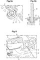
- the Figures 5a and 5b show respectively a perspective view and a sectional view of the guide means 24 in which the shaft 44 of the reduction mechanism 40 is housed.
- the guide means comprises an axial groove 47 making it possible to facilitate the insertion of the shaft 44. This axial groove 47 allows the air to be expelled while preventing the formation of an air pocket during the insertion of the shaft 44 into the guide means 24.
- the guide means 28 may also include such an axial groove.
- the electronic card has an opening 50 of closed contour through which the guide means 24 passes.
- the guide means 24 has a shoulder 55 on which the electronic card rests.
- the guide means 24 serves both for the rotational guidance of the reduction mechanism 40 but also as a means for centering the electronic card 11 in the case 20.
- the Figure 6 shows the electronic card 11 in contact with pins 37 of the box 20 in order to dissipate the heat produced by the electronic card 11.
- Thermal paste 38 is positioned between the pins 37 and the electronic card 11 in order to improve the transfer of calories from the electronic card 11 to the box 20 which, thanks to its material, dissipates the heat.
- a chute 39 is provided around the periphery of the pins 37 in order to recover the excess thermal paste 38.
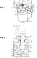
- the Picture 7 shows the positioning of one of the electric motors 1 and its maintenance in position in its dedicated housing 21.
- the electric motor 1 undergoes acceleration and inertia, it must therefore be correctly positioned and maintained in its housing 21.
- the electric motor 1 must also be correctly oriented to allow conduction via its terminals B+, B- with the electronic card 11 and thus avoid a risk of reverse polarity.
- the terminals B+, B- are in contact with the electronic card 11 by pinching in particular visible on the Picture 10 .
- the electric motor 1 must also be correctly centered to ensure the correct operation of the reduction mechanism 40.
- the holding plate 6 performs all these functions. This retaining plate 6 allows the electric motor 1 to be pressed against the bottom of the housing 21.
- the retaining plate 6 is made of metal, preferably of a metal allowing a spring function.
- the retaining plate 6 is fixed to the box 20 by means of fixing means 7, in particular screws.
- the casing 20 comprises a rib 48 in the shape of an arc of a circle made in order to center the retaining plate 6 with respect to the casing 20, the retaining plate 6 having a shape substantially complementary to the rib 48.
- the retaining plate 6 comprises also a curved leg 49 in order to index the plate of support 6 and the electric motor 1, the curved leg 49 being directed towards the electric motor 1.
- the Picture 8 shows in more detail the guiding of the shaft 45. Due to the high forces and torques to control the change of transmission ratios, the guiding of the shaft 45 must be robust. To do this, the shaft 45 is guided in rotation by a bearing 36 and a bearing 51, which makes it possible to absorb the radial loads.
- Bearing 36 is a ball bearing and bearing 51 is a plain bearing.
- the guide means 32 is a through hole and has three bores of different diameters in which the bearing 36, the bearing 51 and a lip seal 52 are mounted.
- the bearing 36 is mounted in a first bore in order to guide the shaft 45 of the toothed sector pinion 46 and the pin 8 mounted on the connecting rod 9 in rotation.
- the bearing 36 is preferably sealed so as not to allow impurities to enter. in the internal volume defined by the housing 20 and the cover 30.
- the inner ring of the ball bearing 36 is mounted on the shaft 45 and the outer ring is housed in a first bore of the guide means 32.
- the internal wall of the bearing 51 is in contact with the shaft 45 and the external wall is in contact with a second bore of the guide means 32.
- the bearing 51 is for example an anti-friction plain bearing made of metal-polymer.
- the plain bearing can be made of bronze.
- Bearing 36 is on the outer side of cover 30 and bearing 51 is on the inner side of cover 30.
- a lip seal 52 is positioned in a third bore of the guide means 32 between the ball bearing 36 and the bearing 51.
- This lip seal 52 makes it possible to seal the inside of the actuator .
- the actuator 10 is mounted directly on the vehicle gearbox, so the pin 8, the connecting rod 9 and the ball bearing 36 are in direct contact with the gearbox lubricant.
- the ball bearing 36 is thus constantly lubricated by the gearbox lubricant.
- the lip seal 52 makes it possible to separate a wet space, namely the interior of the vehicle's gearbox, and a dry space, namely the interior of the actuator 10.
- lips 52 is housed in a shoulder of the guide means 32.
- the lip of the seal 52 is in contact with the shaft 45.
- the lip seal 52 is in contact with one end of the bearing 51.
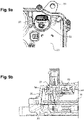
- the Figures 9a and 9b show in detail the electrical connector 27 for powering the electric motors 1 and all the electrical components necessary for the operation of the actuator 10.
- the electrical connector 27 comprises electrical tracks capable of being connected to a external connector.
- the electrical connector comprises means of connection to the electronic card 11.
- the electrical connector 27 is entirely made of plastic and is mounted in an opening of the box 20.
- the electrical connector 27 comprises a membrane 53, more precisely a semi-permeable membrane, that is to say that it is permeable to gases, in particular air and impermeable to liquids, in particular water.
- the membrane 53 is hydrophobic and, where appropriate, oleophobic, and may have a microporous coating.
- the membrane 53 can be fixed by various means on the electrical connector 27, such as via a ring clipped on the electrical connector 27. Alternatively, the membrane 53 can be glued or welded on the electrical connector. Such a membrane thus makes it possible to limit the risks of condensation and excess pressure within the actuator 10, and thus increases the service life while improving the operation of the actuator.
- a joint 54 visible on the Figure 9b is positioned between the electrical connector 27 and the box 20 in order to guarantee the tightness of the actuator. Seal 54 is received in an annular groove of electrical connector 27. Electrical connector 27 is screwed or clipped onto housing 20.
- the Picture 10 shows the actuator 10 in the mounted position on the gearbox of the vehicle. Sealing between the gearbox and the actuator 10 is achieved by the seal 34 mounted in a groove 33 of the actuator 10, more precisely of the cover 30.
- the seal 34 is preferably a polymer seal. The use of a polymer seal 34 is preferred to the use of a flat metal seal as is customary in the field.
- the Picture 11 shows an alternative embodiment of actuator 10. Unlike the previous embodiment, pin 80 is spherical and no longer conical. This makes it possible to adapt to a greater variety of mobile motor vehicle transmission components.
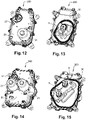
- the Figures 12 to 15 show two other embodiments of the actuator 10.
- an actuator 200 is visible in which there is only one electric motor associated with a pin 8 via a reduction mechanism.
- an actuator 300 can be seen in which there are two electric motors associated with two pins 8 via two reduction mechanisms.
- the operation of the actuators 200, 300 is similar to the operation of the actuator 10, only the number of electric motor, reduction mechanism and pin differs according to the embodiments.
- Such an electric actuator 10, 100, 200, 300 has a compact structure and a small footprint. Furthermore, it is possible to use many standard commercial elements, such as electric motors and toothed wheels. The cost of such an electric actuator is also relatively low and can be easily integrated into existing transmission systems.
Landscapes
- Engineering & Computer Science (AREA)
- General Engineering & Computer Science (AREA)
- Mechanical Engineering (AREA)
- Power Engineering (AREA)
- Connection Of Motors, Electrical Generators, Mechanical Devices, And The Like (AREA)
Abstract
Description
- L'invention concerne un actionneur pour l'actionnement d'au moins un organe mobile. Elle trouve son application, notamment dans le domaine des actionneurs pour les transmissions de véhicule automobiles. De nombreuses autres applications sont cependant possibles.
- Plus précisément, l'invention concerne un actionneur pour le changement de rapports d'une transmission ou boite de vitesses de véhicule automobile. Un tel actionneur trouve son utilité dans une transmission hybride de véhicule automobile, comportant d'une part un moteur thermique d'entrainement, et d'autre part une machine électrique.
- Il existe un besoin de changer les rapports de la transmission afin que le moteur thermique et/ou la machine électrique fonctionnent dans leur plage d'utilisation optimale. L'actionneur selon l'invention remplit cette fonction.
- Il est connu du document
WO2018/146393A1 un actionneur pour le changement de rapports d'une boite de vitesses comprenant un moteur électrique et un axe de fourchette déplacé axialement pour engager ou désengager un rapport de la boite de vitesses. Cet actionneur comporte des moyens de démultiplication de mouvement de rotation entre l'arbre de sortie du moteur électrique et un pion déporté par rapport à l'axe de rotation du moteur électrique, le pion étant engagé dans une ouverture oblongue d'un système à crabot, de manière à provoquer le déplacement axial de l'axe de fourchette en débattant linéairement le long de l'ouverture sous l'action du moteur électrique. - Cette solution a l'inconvénient de proposer un moyen de démultiplication volumineux, ce qui va à l'encontre des objectifs de l'industrie automobile visant à réduire le poids et l'encombrement des composants. De plus, aucun moyen de guidage en rotation de l'arbre soutenant le pion n'est proposé. Cela est d'autant plus problématique que les efforts radiaux pour effectuer les changements de rapports sont importants.
- La présente invention a pour objet une amélioration des solutions actuelles, notamment en proposant une solution ayant pour but de rendre le plus compact possible un tel actionneur pour le changement de rapports d'une transmission de véhicule automobile, tout en garantissant un guidage supportant les efforts liés aux changements de rapports de la transmission.
- Le terme transmission est synonyme de boite de vitesses d'un véhicule automobile.
- Plus particulièrement, l'invention concerne un actionneur pour l'actionnement d'au moins un organe mobile d'une transmission de véhicule automobile, ledit actionneur comprenant un boitier et un couvercle définissant un volume interne dans lequel sont logés au moins un moteur électrique ayant un stator et un rotor monté sur un arbre de rotor s'étendant selon un axe X1, un pignon moteur fixé à l'extrémité de l'arbre opposée au rotor, un mécanisme de démultiplication entrainé par le pignon moteur, un pion monté mobile en rotation à l'extrémité d'un arbre s'étendant selon un axe X3 et apte à être engagé dans l'organe mobile de la transmission, l'arbre du pion est guidé en rotation par un roulement et un palier lisse.
- Ainsi, un actionneur selon l'invention pourra résoudre les problèmes exposés ci-dessus. En particulier, l'usage à la fois d'un roulement et d'un palier lisse pour guider en rotation un même arbre permet de supporter les efforts radiaux imposés par la transmission sur le pion et son arbre.
- Selon l'invention, un joint est disposé axialement entre le roulement et le palier lisse selon l'axe X3. Ce joint est préférentiellement un joint à lèvres.
- Egalement selon l'invention, le boitier et le couvercle présentent chacun des moyens de guidage du mécanisme de démultiplication. Le couvercle comprend un trou débouchant ayant trois alésages de diamètres différents. Le roulement, le joint et le palier lisse sont chacun disposés dans un des trois alésages. Le roulement se trouve du côté externe du couvercle et le palier lisse se trouve du côté interne du couvercle.
- Selon une caractéristique de l'invention, le pion est monté déporté selon un axe X4 par rapport à l'arbre du pion par l'intermédiaire d'une bielle. Le pion est apte à être engagé dans une ouverture, par exemple une ouverture oblongue, de manière à provoquer le déplacement axial d'une fourchette en débattant linéairement le long de l'ouverture sous l'action du moteur électrique. Le pion est apte à débattre dans l'ouverture autour d'une position centrale de point mort et deux positions extrêmes.
- De manière avantageuse, l'actionneur comprend une carte électronique pour l'alimentation du stator et le pilotage du moteur électrique, ladite carte électronique est située axialement selon l'axe X1 entre le moteur électrique et le pignon moteur.
- Selon l'invention, un aimant est fixé sur l'arbre du pion à l'extrémité opposée au pion, l'aimant est fixé au droit d'un capteur fixé sur la carte électronique permettant de détecter la position du pion.
- Préférentiellement, le boitier comprend une gorge périphérique dans laquelle un joint d'étanchéité est disposé afin d'assurer une étanchéité entre le boitier et le couvercle.
- Selon l'invention, l'actionneur est apte à être fixé directement sur la transmission du véhicule et la surface externe du couvercle présente une gorge dans laquelle est positionnée un joint d'étanchéité afin d'assurer l'étanchéité entre la transmission et le couvercle de l'actionneur.
- Selon l'invention, le mécanisme de démultiplication est situé cinématiquement entre le pignon moteur et le pion. Le mécanisme de démultiplication comprend au moins une roue dentée montée sur au moins un arbre. Plus précisément, le mécanisme de démultiplication comprend une roue à pignons étagés et un pignon à secteur denté.
- Selon l'invention, la roue à pignons étagés et le pignon à secteur denté s'étendent chacun selon un plan orthogonal à l'axe X1. Cette architecture de mécanisme de démultiplication permet d'obtenir un actionneur particulièrement compact.
- De manière plus précise, la roue à pignons étagés comprend un premier pignon et un deuxième pignon, le premier pignon est couplé avec le pignon moteur et le deuxième pignon est couplé avec le pignon à secteur denté, la roue à pignons étagés est montée sur un arbre s'étendant selon un axe X2 décalé radialement par rapport à l'axe X1 de l'arbre du moteur électrique. De préférence, la roue à pignons étagés est monobloc, le premier pignon et le deuxième pignon sont coaxiaux.
- Selon l'invention, le secteur denté du pignon s'étend dans une plage angulaire comprise entre 90° et 180°, de préférence entre 100° et 120°. En variante, le secteur denté du pignon peut s'étendre à 360°. Le pignon à secteur denté est monté sur un arbre s'étendant selon un axe X3 décalé radialement par rapport aux axes X1 et X2.
- Selon une caractéristique additionnelle de l'invention, le pion est monté déporté selon un axe X4 à une extrémité de l'arbre du pignon à secteur denté par l'intermédiaire d'une bielle.
- Selon l'invention, les axes X1, X2, X3 et X4 sont parallèles.
- Selon une caractéristique de l'invention, l'actionneur est configuré pour le changement de rapports d'une transmission de véhicule automobile, notamment une transmission hybride.
- Avantageusement, l'actionneur selon l'invention comprend trois moteurs électriques, chaque moteur électrique étant associé à son propre mécanisme de démultiplication et son propre pion. De cette manière, l'actionneur est apte à piloter le changement de six rapports de transmission. En effet, chaque moteur électrique, via son propre mécanisme de démultiplication est apte à déplacer le pion associé dans deux positions extrêmes correspondant chacune à un rapport de la transmission. En d'autres termes, chaque moteur électrique, via son propre mécanisme de démultiplication et son pion associé est apte à piloter deux rapports de la transmission du véhicule. L'actionneur électrique selon l'invention avec ses trois moteurs électriques trouve un intérêt dans les transmissions à six rapports.
- Par exemple, dans le contexte de la transmission hybride divulguée dans les documents
WO2015/197927A1 etWO2019/219294A1 , le premier moteur électrique de l'actionneur selon l'invention peut être lié à deux rapports associés de la machine électrique tandis que le second moteur électrique de l'actionneur selon l'invention peut être lié à deux rapports du moteur thermique, par exemple les rapports 1 et 3 et le troisième moteur électrique de l'actionneur selon l'invention peut être lié à deux autres rapports du moteur thermique, par exemple les rapports 2 et 4. - D'autres caractéristiques et avantages de l'invention ressortiront à la lecture qui suit d'exemples de réalisations détaillés, en référence aux Figures annexées.
- La
Figure 1 représente l'actionneur selon l'invention depuis une vue de dessous ; - La
Figure 2 représente l'actionneur selon l'invention depuis une vue de dessus ; - La
Figure 3 représente une vue en perspective et en coupe partielle de l'actionneur selon l'invention ; - La
Figure 4 représente une vue en coupe et en perspective de l'actionneur selon l'invention ; - La
Figure 5a et laFigure 5b représentent respectivement une vue en perspective et une vue en coupe d'un moyen de guidage d'un arbre du mécanisme de démultiplication ; - La
Figure 6 représente une vue en perspective du contact entre la carte électronique et le boitier ; - La
Figure 7 représente une vue en perspective coupée d'une plaque de maintien d'un moteur électrique ; - La
Figure 8 représente une vue en coupe d'un moyen de guidage d'un arbre du mécanisme de démultiplication ; - La
Figure 9a et laFigure 9b représentent respectivement une vue en perspective et une vue en coupe d'un connecteur électrique de l'actionneur selon l'invention ; - La
Figure 10 représente une vue en coupe de l'actionneur électrique selon l'invention fixé sur une boite de vitesses d'un véhicule automobile ; - La
Figure 11 représente un mode de réalisation alternatif de l'invention ; - La
Figure 12 et laFigure 13 représentent une variante de réalisation de l'actionneur selon l'invention ; - La
Figure 14 et laFigure 15 représentent une autre variante de réalisation de l'actionneur selon l'invention. - La
Figure 1 représente un actionneur 10 selon l'invention. L'actionneur 10 est formé par deux parties principales, à savoir un boitier 20 et un couvercle 30 dans lesquels viennent se loger plusieurs éléments. CetteFigure 1 est focalisée sur le boitier 20 de l'actionneur 10. Le boitier 20 est réalisé en métal comme par exemple en aluminium ou en alliage d'aluminium. En variante, le boitier 20 peut être réalisé dans une matière plastique injectable. Le boitier 20 a pour fonction d'accueillir les moteurs électriques 1 dans des logements dédiés 21. Le boitier 20 forme ainsi un boitier commun aux moteurs électriques 1. - Dans un premier mode de réalisation de l'invention, trois moteurs électriques 1 sont logés dans trois logements respectifs 21. Les logements 21 des moteurs électriques 1 sont réalisés de forme complémentaire à la forme des moteurs électriques. Des renforts 22 sous forme de nervures sont prévus entre chaque logement 21 pour rigidifier le boitier 20.
- Le boitier 20 intègre également un connecteur électrique 27 afin d'alimenter les moteurs électriques 1 et tous les composants électriques nécessaires au fonctionnement de l'actionneur 10.
- Le boitier 20 est assemblé au couvercle 30 par l'intermédiaire de vis de fixation 23 situées au niveau du pourtour du boitier 20 et du couvercle 30.
- En
Figure 2 est visible le couvercle 30 de l'actionneur 10. Le couvercle 30 est réalisé en métal comme par exemple en aluminium ou en alliage. En variante, le couvercle 30 peut être réalisé dans une matière plastique injectable. Dans le cas de la présente invention, le boitier 20 et le couvercle 30 sont réalisés en aluminium coulé sous haute pression (en anglais « die casting »). Le boitier 20 ou le couvercle 30 peut recevoir un circuit de refroidissement si les températures environnantes sont trop élevées. - L'actionneur 10 est apte à être fixé directement sur la transmission du véhicule, comme par exemple la boite de vitesses, par l'intermédiaire de moyens de fixation 31, notamment des ouvertures dans lesquels passent des vis. La surface externe du couvercle 30 présente une gorge 33 dans laquelle est positionnée un joint d'étanchéité 34 afin d'assurer l'étanchéité entre la transmission et le couvercle 30. Les éléments qui se trouvent à l'intérieur du contour fermé du joint 34 sont directement en contact avec la transmission du véhicule. Dans le cas présent trois pions 8 sont aptes à être chacun engagés dans un organe mobile de la transmission, lié par exemple à une fourchette et/ou un crabot. Les pions 8 sont donc situés à l'extérieur du couvercle 30. Les pions 8 ont une forme coopérant avec leur organe mobile respectif, par exemple une forme conique.
- Chaque pion 8 est apte à être engagé dans une ouverture, par exemple une ouverture oblongue, d'un crabot de manière à provoquer le déplacement axial d'une fourchette en débattant linéairement le long de l'ouverture sous l'action du moteur électrique. Le pion est apte à débattre dans l'ouverture autour d'une position centrale de point mort et deux positions extrêmes. Cette cinématique d'actionnement est décrite dans le document publié
WO2018/146393A1 . - La
Figure 3 montre l'intérieur de l'actionneur 10 selon l'invention. Bien que cetteFigure 3 soit une vue en perspective et en coupe partielle focalisée sur un seul moteur électrique 1 et sa cinématique associée jusqu'au pion 8, les trois moteurs électriques 1 et les cinématiques d'actionnement des pions 8 sont toutes indépendantes mais identiques dans l'actionneur 10. - Sur cette
Figure 3 est donc visible le boitier 20 et son logement 21 dans lequel sont logés les moteurs électriques 1. Afin de maintenir fixement les moteurs électriques 1 dans le boitier 20, des plaques de maintien 6 sont utilisées de manière à plaquer les moteurs électriques 1 au fond de leur logement 21 respectif. - Les moteurs électriques 1 sont à courant continu et sont chacun constitués d'un stator 2 et un rotor 3 monté sur un arbre de rotor 4 s'étendant selon un axe X1. Un pignon moteur 5 est fixé à l'extrémité de chaque arbre du côté opposé au rotor 3 et permet d'entrainer un mécanisme de démultiplication 40 formé par des roues dentées 41, 42, 46 montées sur des arbres 44, 45.
- Le mécanisme de démultiplication 40 est situé cinématiquement entre le pignon moteur 5 et le pion 8 et comprend une roue à pignons étagés 43 et un pignon à secteur denté 46.
- La roue à pignons étagés 43 comprend un premier pignon 41 et un deuxième pignon 42, le premier pignon 41 est couplé avec le pignon moteur 5 et le deuxième pignon 42 est couplé avec le pignon à secteur denté 46, la roue à pignons étagés 43 est montée sur l'arbre 44 s'étendant selon un axe X2 et décalé radialement par rapport à l'axe X1 de l'arbre 4 du moteur électrique 1. Le premier pignon 41 a un diamètre plus grand que le deuxième pignon 42. Les roues dentées 41, 42, 46 sont surmoulées sur les arbres 44, 45. Les roues dentées 41, 42, 46 sont par exemple en polyphtalamide renforcé de fibres de verre (PPA), présentant une rigidité et une résistance très élevées, ainsi qu'une résistance aux hautes températures et aux produits chimiques. En variante, les roues dentées peuvent être en polyamide renforcé de fibres de verre (PA).
- La roue à pignons étagés 41, 42, 43 et le pignon à secteur denté 46 s'étendent chacun selon un plan orthogonal à l'axe X1.
- Le secteur denté du pignon 46 s'étend dans une plage angulaire comprise entre 90° et 180°, de préférence entre 100° et 120°. Le pignon à secteur denté 46 est monté sur l'arbre 45 s'étendant selon un axe X3 décalé radialement par rapport aux axes X1 et X2. Le pion 8 est monté déporté selon un axe X4 à une extrémité de l'arbre 45 du pignon à secteur denté 46 par l'intermédiaire d'une bielle 9. Cette bielle 9 est également située à l'extérieur du couvercle 30. Les axes X1, X2, X3 et X4 sont parallèles.
- Une carte électronique 11 servant à l'alimentation du stator 2 et au pilotage de chaque moteur électrique 1 est situé axialement selon l'axe X1 entre chaque moteur électrique 1 et chaque pignon moteur 5. Le boitier 20 définit un premier volume dans lequel sont logés les moteurs électriques 1 et la carte électronique 11 formant ainsi un sous-ensemble électronique.
- La carte électronique 11 est fixée au boitier 20 par l'intermédiaire de moyens de fixation 13, notamment des vis. Le contour extérieur de la carte électronique 11 épouse sensiblement le contour intérieur du boitier 20. La carte électronique 11 comporte trois ouvertures 12 de contour fermé qui sont chacune traversées par l'arbre 4 de rotor de chaque moteur électrique 1.
- La carte électronique 11 permet la gestion de l'électronique de puissance, de l'électronique de commande et de la fonction autodiagnostic. Par conséquent, toutes les fonctions (détection de la position des pions 8 pour un contrôle en boucle fermée, alimentation électrique et connexion au bus du véhicule) peuvent se trouver sur la carte électronique. Ainsi, le circuit électronique 11 intègre tous les composants électroniques nécessaires au fonctionnement de l'actionneur électrique comme par exemple des capteurs 56 de rotation en vis-à-vis des arbres 45 afin de connaitre la position des pions 8. De plus, l'alimentation électrique des moteurs 1 est à proximité du connecteur électrique 27. La carte électronique 11 est relié aux moteurs électriques 1 par des contacts à sertir ou à souder.
- Le mécanisme de démultiplication 40 est logé dans le couvercle 30 qui définit un second volume. Le boitier 20 et le couvercle 30 présentent chacun des moyens de guidage 24, 32 des arbres 44, 45 du mécanisme de démultiplication 40.
- Le boitier 20 comprend une gorge périphérique 25 dans laquelle un joint d'étanchéité 26 est disposé afin d'assurer une étanchéité entre le boitier 20 et le couvercle 30.
- La
Figure 4 permet de mieux illustrer la cinématique entre le moteur électrique 1, le mécanisme de démultiplication 40 et le pion 8. - Le boitier 20 comporte un moyen de guidage 24 sous forme de trou borgne recevant une extrémité de l'arbre 44 de la roue à pignons étagés 43. Le couvercle 30 comporte également un moyen de guidage 28 sous forme de trou borgne recevant l'autre extrémité de l'arbre 44 de la roue à pignons étagés 43.
- Le couvercle 30 comprend également un trou débouchant 32 pour le passage et le guidage de l'arbre 45 du pignon à secteur denté 46.
- Sur son extrémité faisant face à la carte électronique 11, l'arbre 45 comprend un aimant 35 permettant de détecter la position du pion 8 grâce à un capteur 56 fixé sur la carte électronique 11. Le capteur 56 est de préférence un capteur à effet Hall.
- Les
Figures 5a et 5b montrent respectivement une vue en perspective et une vue en coupe du moyen de guidage 24 dans lequel vient se loger l'arbre 44 du mécanisme de démultiplication 40. Le moyen de guidage comporte une rainure axiale 47 permettant de faciliter l'insertion de l'arbre 44. Cette rainure axiale 47 permet de chasser l'air tout en empêchant la formation d'une poche d'air lors de l'insertion de l'arbre 44 dans le moyen de guidage 24. Le moyen de guidage 28 peut également comporter une telle rainure axiale. La carte électronique possède une ouverture 50 de contour fermé traversée par le moyen de guidage 24. Le moyen de guidage 24 possède un épaulement 55 sur lequel vient s'appuyer la carte électronique. Le moyen de guidage 24 sert à la fois pour le guidage en rotation du mécanisme de démultiplication 40 mais également de moyen de centrage de la carte électronique 11 dans le boitier 20. - La
Figure 6 montre la carte électronique 11 en contact avec des pions 37 du boitier 20 afin de dissiper la chaleur produite par la carte électronique 11. De le pâte thermique 38 est positionnée entre les pions 37 et la carte électronique 11 afin d'améliorer le transfert de calories depuis la carte électronique 11 vers le boitier 20 qui, grâce à sa matière, dissipe la chaleur. Une goulotte 39 est prévue sur le pourtour des pions 37 afin de récupérer le surplus de pâte thermique 38. - La
Figure 7 montre le positionnement d'un des moteurs électriques 1 et son maintien en position dans son logement 21 dédié. En fonctionnement, le moteur électrique 1 subit une accélération et une inertie, il faut donc qu'il soit correctement positionné et maintenu dans son logement 21. Le moteur électrique 1 doit également être correctement orienté pour permettre la conduction via ses bornes B+, B- avec la carte électronique 11 et ainsi éviter un risque d'inversion de polarité. Les bornes B+, B- sont en contact avec la carte électronique 11 par pincement notamment visible sur laFigure 10 . Le moteur électrique 1 doit aussi être correctement centré pour assurer le bon fonctionnement du mécanisme de démultiplication 40. La plaque de maintien 6 réalise toutes ces fonctions. Cette plaque de maintien 6 permet de plaquer le moteur électrique 1 au fond du logement 21. La plaque de maintien 6 est réalisée en métal, de préférence dans un métal permettant une fonction de ressort. La plaque de maintien 6 est fixée au boitier 20 par l'intermédiaire de moyens de fixation 7, notamment des vis. Le boitier 20 comprend une nervure 48 en forme d'arc de cercle réalisée afin de centrer la plaque de maintien 6 par rapport au boitier 20, la plaque de maintien 6 ayant une forme sensiblement complémentaire à la nervure 48. La plaque de maintien 6 comprend également une patte courbée 49 afin d'indexer la plaque de maintien 6 et le moteur électrique 1, la patte courbée 49 étant dirigées vers le moteur électrique 1. - La
Figure 8 montre plus en détails le guidage de l'arbre 45. En raison des efforts et des couples élevés pour contrôler le changement des rapports de la transmission, le guidage de l'arbre 45 doit être robuste. Pour se faire, l'arbre 45 est guidé en rotation par un roulement 36 et un palier 51, ce qui permet d'absorber les charges radiales. Le roulement 36 est un roulement à billes et le palier 51 est un palier lisse. - Le moyen de guidage 32 est un trou débouchant et possède trois alésages de diamètres différents dans lesquels le roulement 36, le palier 51 et un joint à lèvres 52 sont montés.
- Le roulement 36 est monté dans un premier alésage afin de guider en rotation l'arbre 45 du pignon à secteur denté 46 et le pion 8 monté sur la bielle 9. Le roulement 36 est de préférence étanche afin de ne pas laisser entrer d'impureté dans la volume interne défini par le boitier 20 et le couvercle 30. La bague interne du roulement à billes 36 est montée sur l'arbre 45 et la bague externe est logée dans un premier alésage du moyen de guidage 32.
- La paroi interne du palier 51 est en contact avec l'arbre 45 et la paroi externe est en contact avec un deuxième alésage du moyen de guidage 32. Le palier 51 est par exemple un palier lisse antifriction réalisé en métal-polymère. En variante, le palier lisse peut être réalisé en bronze.
- Le roulement 36 se trouve du côté externe du couvercle 30 et le palier 51 se trouve du côté interne du couvercle 30.
- Axialement selon l'axe X3, un joint à lèvre 52 est positionné dans un troisième alésage du moyen de guidage 32 entre le roulement à billes 36 et le palier 51. Ce joint à lèvre 52 permet de rendre étanche l'intérieur de l'actionneur. En effet, l'actionneur 10 est monté directement sur la boite de vitesses du véhicule, ainsi le pion 8, la bielle 9 et le roulement à billes 36 sont en contact direct avec le lubrifiant de la boite de vitesses. Le roulement à billes 36 est ainsi constamment lubrifié par le lubrifiant de la boite de vitesse. Autrement dit, le joint à lèvres 52 permet de séparer un espace humide, à savoir l'intérieur de la boite de vitesses du véhicule, et un espace sec, à savoir l'intérieur de l'actionneur 10. Le joint à lèvres 52 est logé dans un épaulement du moyen de guidage 32. La lèvre du joint 52 est en contact avec l'arbre 45. Le joint à lèvres 52 est en contact avec une extrémité du palier 51.
- Les
Figures 9a et 9b montrent en détail le connecteur électrique 27 permettant d'alimenter les moteurs électriques 1 et tous les composants électriques nécessaires au fonctionnement de l'actionneur 10. Du coté externe au boitier 20, le connecteur électrique 27 comprend des pistes électriques aptes à êtres raccordées à un connecteur externe. Du coté interne au boitier 20, le connecteur électrique comprend des moyens de connexion à la carte électronique 11. Le connecteur électrique 27 est entièrement réalisé en plastique et vient se monter dans une ouverture du boitier 20. Le connecteur électrique 27 comprend une membrane 53, plus précisément une membrane semi-perméable, c'est-à-dire qu'elle est perméable aux gaz, notamment l'air et imperméable aux liquides, notamment l'eau. La membrane 53 est hydrophobe et le cas échéant oléophobe, et peut présenter un revêtement microporeux. La membrane 53 peut être fixée par différents moyens sur le connecteur électrique 27, comme par l'intermédiaire d'une bague clippée sur le connecteur électrique 27. Alternativement, la membrane 53 peut être collée ou soudée sur le connecteur électrique. Une telle membrane permet ainsi de limiter les risques de condensation et d'excès de pression au sein de l'actionneur 10, et augmente ainsi la durée de vie tout en améliorant le fonctionnement de l'actionneur. - Un joint 54 visible sur la
Figure 9b , de type torique, est positionné entre le connecteur électrique 27 et le boitier 20 afin de garantir l'étanchéité de l'actionneur. Le joint 54 est reçu dans une gorge annulaire du connecteur électrique 27. Le connecteur électrique 27 est vissé ou clippé sur le boitier 20. - La
Figure 10 montre l'actionneur 10 en position montée sur la boite de vitesses BV du véhicule. L'étanchéité entre la boite de vitesse BV et l'actionneur 10 est réalisée par le joint 34 en monté dans une gorge 33 de l'actionneur 10, plus précisément du couvercle 30. Le joint 34 est de préférence un joint en polymère. L'utilisation d'un joint 34 en polymère est préféré à l'utilisation d'un joint plat en métal comme il est d'usage dans le domaine. - La
Figure 11 montre une variante de réalisation de l'actionneur 10. A la différence du mode de réalisation précédent le pion 80 est sphérique et non plus conique. Ceci permet de s'adapter à une plus grande diversité d'organes mobiles de transmissions de véhicules automobile. - Les
Figures 12 à 15 montrent deux autres variantes de réalisation de l'actionneur 10. Sur lesFigures 12 et 13 est visible un actionneur 200 dans lequel il n'y a qu'un seul moteur électrique associé à un pion 8 via un mécanisme de démultiplication. Sur lesFigures 14 et 15 est visible un actionneur 300 dans lequel il y a deux moteurs électriques associés à deux pions 8 via deux mécanismes de démultiplication. Le fonctionnement des actionneurs 200, 300 est similaire au fonctionnement de l'actionneur 10, seul le nombre de moteur électrique, de mécanisme de démultiplication et de pion diffère selon les modes de réalisations. - Un tel actionneur électrique 10, 100, 200, 300 présente une structure compacte et un faible encombrement. Par ailleurs, il est possible d'utiliser de nombreux éléments standards du commerce, tels que des moteurs électriques et des roues dentées. Le coût d'un tel actionneur électrique est par ailleurs relativement faible et peut être intégré aisément sur les systèmes de transmission existants.
- Bien que l'invention ait été décrite en liaison avec plusieurs modes de réalisations, il est bien évident qu'elle n'y est nullement limitée et qu'elle comprend tous les équivalents techniques des moyens décrits ainsi que leurs combinaisons si celles-ci entrent dans le cadre de l'invention.
- Dans les revendications, tout signe de référence entre parenthèses ne saurait être interprété comme une limitation de la revendication.
Claims (15)
- Actionneur (10, 100, 200, 300) pour l'actionnement d'au moins un organe mobile d'une transmission de véhicule automobile, ledit actionneur comprenant un boitier (20) et un couvercle (30) définissant un volume interne dans lequel sont logés au moins un moteur électrique (1) ayant un stator (2) et un rotor (3) monté sur un arbre de rotor (4) s'étendant selon un axe X1, un pignon moteur (5) fixé à l'extrémité de l'arbre (4) opposée au rotor (3), un mécanisme de démultiplication (40) entrainé par le pignon moteur (5), l'actionneur comprend en outre un pion (8) monté mobile en rotation à l'extrémité d'un arbre (45) s'étendant selon un axe X3 et apte à être engagé dans l'organe mobile de la transmission, caractérisé en ce que l'arbre (45) du pion (8) est guidé en rotation par un roulement (36) et un palier lisse (51).
- Actionneur selon la revendication 1, caractérisé en ce qu'un joint (52), de préférence à lèvres, est disposé axialement entre le roulement (36) et le palier lisse (51) selon l'axe X3.
- Actionneur selon la revendication 1 ou 2, caractérisé en ce que le boitier (20) et le couvercle (30) présentent chacun des moyens de guidage (24, 28) du mécanisme de démultiplication (40).
- Actionneur selon l'une des revendications 2 à 3, caractérisé en ce que le couvercle (30) comprend un trou débouchant (32) ayant trois alésages de diamètres différents, le roulement (36), le joint (52) et le palier lisse (51) étant chacun disposés dans un des trois alésages, le roulement (36) se trouve du côté externe du couvercle (30) et le palier lisse (51) se trouve du côté interne du couvercle (30).
- Actionneur selon l'une des revendications précédentes, caractérisé en ce que le pion (8) est monté déporté selon un axe X4 par rapport à l'arbre (45) par l'intermédiaire d'une bielle (9).
- Actionneur selon l'une des revendications précédentes, caractérisé en ce qu'il comprend une carte électronique (11) pour l'alimentation du stator (2) et le pilotage du moteur électrique (1), ladite carte électronique (11) est située axialement selon l'axe X1 entre le moteur électrique (1) et le pignon moteur (5).
- Actionneur selon la revendication 6, caractérisé en ce qu'un aimant (35) est fixé sur l'arbre (45) du pion (8) à l'extrémité opposée au pion (8), l'aimant (35) étant fixé au droit d'un capteur (56) fixé sur la carte électronique (11) permettant de détecter la position du pion (8).
- Actionneur selon l'une des revendications précédentes, caractérisé en ce que le boitier (20) comprend une gorge périphérique (25) dans laquelle un joint d'étanchéité (26) est disposé afin d'assurer une étanchéité entre le boitier (20) et le couvercle (30).
- Actionneur selon l'une des revendications précédentes, caractérisé en ce qu'il est apte à être fixé directement sur la transmission du véhicule et en ce que la surface externe du couvercle (30) présente une gorge (33) dans laquelle est positionnée un joint d'étanchéité (34) afin d'assurer l'étanchéité entre la transmission et le couvercle (30) de l'actionneur.
- Actionneur selon l'une des revendications précédentes, caractérisé en ce que le mécanisme de démultiplication (40) comprend au moins une roue dentée (43, 46) montée sur au moins un arbre (44, 45) et est situé cinématiquement entre le pignon moteur (5) et le pion (8).
- Actionneur selon la revendication 10 caractérisé en ce que le mécanisme de démultiplication (40) comprend une roue à pignons étagés (41, 42, 43) et un pignon à secteur denté (46).
- Actionneur selon la revendication 11 caractérisé en ce que la roue à pignons étagés (41, 42, 43) et le pignon à secteur denté (46) s'étendent chacun selon un plan orthogonal à l'axe X1.
- Actionneur selon la revendication 11 ou 12 caractérisé en ce que la roue à pignons étagés (43) comprend un premier pignon (41) et un deuxième pignon (42), le premier pignon (41) est couplé avec le pignon moteur (5) et le deuxième pignon (42) est couplé avec le pignon à secteur denté (46), la roue à pignons étagés (43) est montée sur un arbre (44) s'étendant selon un axe X2 décalé radialement par rapport à l'axe X1 de l'arbre (4) du moteur électrique (1).
- Actionneur selon l'une des revendications 11 à 13 caractérisé en ce que le secteur denté du pignon (46) s'étend dans une plage angulaire comprise entre 90° et 180°, de préférence entre 100° et 120°, le pignon à secteur denté (46) est monté sur l'arbre (45) du pion (8) s'étendant selon un axe X3 décalé radialement par rapport aux axes X1 et X2.
- Actionneur selon l'une des revendications précédentes caractérisé en ce qu'il est configuré pour le changement de rapports d'une transmission de véhicule automobile, notamment une transmission de véhicule hybride.
Applications Claiming Priority (1)
| Application Number | Priority Date | Filing Date | Title |
|---|---|---|---|
| FR2103789A FR3121725B1 (fr) | 2021-04-13 | 2021-04-13 | Actionneur pour l’actionnement d’au moins un organe mobile, notamment pour le changement de rapports d’une transmission de véhicule automobile |
Publications (3)
| Publication Number | Publication Date |
|---|---|
| EP4075024A1 true EP4075024A1 (fr) | 2022-10-19 |
| EP4075024B1 EP4075024B1 (fr) | 2025-03-12 |
| EP4075024C0 EP4075024C0 (fr) | 2025-03-12 |
Family
ID=76034816
Family Applications (1)
| Application Number | Title | Priority Date | Filing Date |
|---|---|---|---|
| EP22167540.8A Active EP4075024B1 (fr) | 2021-04-13 | 2022-04-11 | Actionneur pour l'actionnement d'au moins un organe mobile, notamment pour le changement de rapports d'une transmission de véhicule automobile |
Country Status (5)
| Country | Link |
|---|---|
| US (1) | US11732799B2 (fr) |
| EP (1) | EP4075024B1 (fr) |
| CN (1) | CN115199743B (fr) |
| ES (1) | ES3029210T3 (fr) |
| FR (1) | FR3121725B1 (fr) |
Citations (9)
| Publication number | Priority date | Publication date | Assignee | Title |
|---|---|---|---|---|
| EP1094253B1 (fr) * | 1999-10-18 | 2008-11-26 | Borgwarner, Inc. | Moteur intégré pour commande de changement de vitesses et unité de commande électronique |
| US20080318724A1 (en) * | 2006-07-28 | 2008-12-25 | Thomas Lott | Integrated Drive Element |
| US20110126657A1 (en) * | 2009-11-27 | 2011-06-02 | Stoneridge Control Devices, Inc. | Shift-By-Wire Transmission Range Selector System and Actuator for the Same |
| WO2015197927A1 (fr) | 2014-06-24 | 2015-12-30 | Renault S.A.S | Transmission hybride a machine électrique déportée et procédé de commande de changements de rapports |
| WO2018146393A1 (fr) | 2017-02-07 | 2018-08-16 | Renault S.A.S | Dispositif de transmission de mouvement pour actionneur de passage de vitesses |
| WO2019219294A1 (fr) | 2018-05-15 | 2019-11-21 | Renault S.A.S | Transmission hybride a machine electrique deportee |
| WO2020065088A1 (fr) * | 2018-09-28 | 2020-04-02 | Sonceboz Mechatronics Boncourt Sa | Actionneur électrique |
| CN210397685U (zh) * | 2019-08-19 | 2020-04-24 | 宜宾丰川动力科技有限公司 | 一种换挡机构以及电动车 |
| US20210040672A1 (en) * | 2018-04-27 | 2021-02-11 | Guangdong Welling Motor Manufacturing Co., Ltd. | Driving system of drum washing machine and drum washing machine |
Family Cites Families (10)
| Publication number | Priority date | Publication date | Assignee | Title |
|---|---|---|---|---|
| JPS57206787A (en) * | 1981-06-12 | 1982-12-18 | Toyoda Autom Loom Works Ltd | Volume type fluid compression apparatus |
| DE112007001716T5 (de) * | 2006-11-24 | 2009-05-07 | Aisin AW Co., Ltd., Anjo | Automatikgetriebesteuereinheit und Automatikgetriebe mit diesem |
| DE102011054956B4 (de) * | 2011-10-31 | 2022-05-12 | Minebea Mitsumi Inc. | Antriebseinheit für einen Stellantrieb mit einem Elektromotor und zugehöriger Stellantrieb |
| DE102012007765A1 (de) * | 2012-04-20 | 2013-10-24 | Voith Patent Gmbh | Turbocompoundlagerung zur Anbindung eines Turbocompoundsystems an eine Brennkraftmaschine |
| US20140020491A1 (en) * | 2012-07-18 | 2014-01-23 | Delphi Technologies, Inc. | Compact modular actuator |
| US10955051B2 (en) * | 2017-07-18 | 2021-03-23 | Dura Operating, Llc | Actuator assembly for a transmission shifter |
| JP2019122080A (ja) * | 2017-12-28 | 2019-07-22 | 日本電産トーソク株式会社 | 電動アクチュエータ |
| EP3868589A4 (fr) * | 2019-01-17 | 2021-08-25 | Aisin Corporation | Dispositif d'entraînement de véhicule |
| JP7419620B2 (ja) * | 2020-02-06 | 2024-01-23 | ジヤトコ株式会社 | 動力伝達装置 |
| JP7516898B2 (ja) * | 2020-06-16 | 2024-07-17 | 株式会社アイシン | シフト装置 |
-
2021
- 2021-04-13 FR FR2103789A patent/FR3121725B1/fr active Active
-
2022
- 2022-04-11 ES ES22167540T patent/ES3029210T3/es active Active
- 2022-04-11 EP EP22167540.8A patent/EP4075024B1/fr active Active
- 2022-04-12 US US17/658,959 patent/US11732799B2/en active Active
- 2022-04-13 CN CN202210385098.1A patent/CN115199743B/zh active Active
Patent Citations (9)
| Publication number | Priority date | Publication date | Assignee | Title |
|---|---|---|---|---|
| EP1094253B1 (fr) * | 1999-10-18 | 2008-11-26 | Borgwarner, Inc. | Moteur intégré pour commande de changement de vitesses et unité de commande électronique |
| US20080318724A1 (en) * | 2006-07-28 | 2008-12-25 | Thomas Lott | Integrated Drive Element |
| US20110126657A1 (en) * | 2009-11-27 | 2011-06-02 | Stoneridge Control Devices, Inc. | Shift-By-Wire Transmission Range Selector System and Actuator for the Same |
| WO2015197927A1 (fr) | 2014-06-24 | 2015-12-30 | Renault S.A.S | Transmission hybride a machine électrique déportée et procédé de commande de changements de rapports |
| WO2018146393A1 (fr) | 2017-02-07 | 2018-08-16 | Renault S.A.S | Dispositif de transmission de mouvement pour actionneur de passage de vitesses |
| US20210040672A1 (en) * | 2018-04-27 | 2021-02-11 | Guangdong Welling Motor Manufacturing Co., Ltd. | Driving system of drum washing machine and drum washing machine |
| WO2019219294A1 (fr) | 2018-05-15 | 2019-11-21 | Renault S.A.S | Transmission hybride a machine electrique deportee |
| WO2020065088A1 (fr) * | 2018-09-28 | 2020-04-02 | Sonceboz Mechatronics Boncourt Sa | Actionneur électrique |
| CN210397685U (zh) * | 2019-08-19 | 2020-04-24 | 宜宾丰川动力科技有限公司 | 一种换挡机构以及电动车 |
Also Published As
| Publication number | Publication date |
|---|---|
| EP4075024B1 (fr) | 2025-03-12 |
| ES3029210T3 (en) | 2025-06-23 |
| EP4075024C0 (fr) | 2025-03-12 |
| CN115199743A (zh) | 2022-10-18 |
| CN115199743B (zh) | 2024-04-26 |
| FR3121725A1 (fr) | 2022-10-14 |
| US11732799B2 (en) | 2023-08-22 |
| US20220325794A1 (en) | 2022-10-13 |
| FR3121725B1 (fr) | 2023-07-07 |
Similar Documents
| Publication | Publication Date | Title |
|---|---|---|
| EP4075026B1 (fr) | Actionneur pour l'actionnement d'au moins un organe mobile, notamment pour le changement de rapports d'une transmission de véhicule automobile | |
| EP4075027A1 (fr) | Actionneur pour l'actionnement d'au moins un organe mobile, notamment pour le changement de rapports d'une transmission de véhicule automobile | |
| WO2019129984A1 (fr) | Motoreducteur a encombrement reduit | |
| EP4075024B1 (fr) | Actionneur pour l'actionnement d'au moins un organe mobile, notamment pour le changement de rapports d'une transmission de véhicule automobile | |
| WO2015049437A2 (fr) | Actionneur pour systeme de transmission | |
| FR3121724A1 (fr) | Actionneur pour l’actionnement d’au moins un organe mobile, notamment pour le changement de rapports d’une transmission de véhicule automobile | |
| FR2814297A1 (fr) | Actionneur alimente electriquement, en particulier pour commander un composant de bicyclette | |
| FR3121726A1 (fr) | Actionneur pour l’actionnement d’au moins un organe mobile, notamment pour le changement de rapports d’une transmission de véhicule automobile | |
| EP1956256A1 (fr) | Cage de rétention à réserve de lubrifiant solide comprenant un espace dans les logements de rétention | |
| WO2019025686A1 (fr) | Actionneur d'embrayage | |
| WO2019149540A1 (fr) | Actionneur d'embrayage | |
| FR2859050A1 (fr) | Unite d'entrainement et de transmission comportant au moins deux moteurs pour actionner ou deplacer une piece equipant un vehicule automobile | |
| EP2683580B1 (fr) | Dispositif d'essuie-glace à vis à billes et fourchette | |
| EP2578451A1 (fr) | Actionneur pour phare de véhicule | |
| EP1350977B1 (fr) | Système de commande d'embrayage pour véhicule automobile et dispositif d'entraînement associé | |
| WO2018219620A1 (fr) | Moto-reducteur pour systeme d'essuyage de vehicule automobile | |
| EP4381208B1 (fr) | Actionneur pour l'actionnement d'au moins un organe mobile d'une transmission de véhicule | |
| FR3066969A1 (fr) | Moto-reducteur pour systeme d'essuyage de vehicule automobile | |
| WO2019025688A1 (fr) | Actionneur d'embrayage | |
| FR2995016A1 (fr) | Turbocompresseur de gaz d'echappement | |
| EP3746670B1 (fr) | Actionneur d'embrayage | |
| FR3076329A1 (fr) | Actionneur d'embrayage | |
| EP0615501B1 (fr) | Direction assistee a compensation automatique de jeu | |
| FR3166104A1 (fr) | Dispositif d’actionnement et système de transmission d’un véhicule | |
| FR3069596A1 (fr) | Actionneur d'embrayage |
Legal Events
| Date | Code | Title | Description |
|---|---|---|---|
| PUAI | Public reference made under article 153(3) epc to a published international application that has entered the european phase |
Free format text: ORIGINAL CODE: 0009012 |
|
| STAA | Information on the status of an ep patent application or granted ep patent |
Free format text: STATUS: REQUEST FOR EXAMINATION WAS MADE |
|
| 17P | Request for examination filed |
Effective date: 20220411 |
|
| AK | Designated contracting states |
Kind code of ref document: A1 Designated state(s): AL AT BE BG CH CY CZ DE DK EE ES FI FR GB GR HR HU IE IS IT LI LT LU LV MC MK MT NL NO PL PT RO RS SE SI SK SM TR |
|
| P01 | Opt-out of the competence of the unified patent court (upc) registered |
Effective date: 20230528 |
|
| RAP1 | Party data changed (applicant data changed or rights of an application transferred) |
Owner name: VALEO ELECTRIFICATION |
|
| GRAP | Despatch of communication of intention to grant a patent |
Free format text: ORIGINAL CODE: EPIDOSNIGR1 |
|
| STAA | Information on the status of an ep patent application or granted ep patent |
Free format text: STATUS: GRANT OF PATENT IS INTENDED |
|
| INTG | Intention to grant announced |
Effective date: 20250107 |
|
| GRAS | Grant fee paid |
Free format text: ORIGINAL CODE: EPIDOSNIGR3 |
|
| GRAA | (expected) grant |
Free format text: ORIGINAL CODE: 0009210 |
|
| STAA | Information on the status of an ep patent application or granted ep patent |
Free format text: STATUS: THE PATENT HAS BEEN GRANTED |
|
| AK | Designated contracting states |
Kind code of ref document: B1 Designated state(s): AL AT BE BG CH CY CZ DE DK EE ES FI FR GB GR HR HU IE IS IT LI LT LU LV MC MK MT NL NO PL PT RO RS SE SI SK SM TR |
|
| REG | Reference to a national code |
Ref country code: GB Ref legal event code: FG4D Free format text: NOT ENGLISH |
|
| REG | Reference to a national code |
Ref country code: CH Ref legal event code: EP |
|
| REG | Reference to a national code |
Ref country code: DE Ref legal event code: R096 Ref document number: 602022011592 Country of ref document: DE |
|
| REG | Reference to a national code |
Ref country code: IE Ref legal event code: FG4D Free format text: LANGUAGE OF EP DOCUMENT: FRENCH |
|
| U01 | Request for unitary effect filed |
Effective date: 20250319 |
|
| U07 | Unitary effect registered |
Designated state(s): AT BE BG DE DK EE FI FR IT LT LU LV MT NL PT RO SE SI Effective date: 20250325 |
|
| P04 | Withdrawal of opt-out of the competence of the unified patent court (upc) registered |
Free format text: CASE NUMBER: APP_13928/2025 Effective date: 20250321 |
|
| U20 | Renewal fee for the european patent with unitary effect paid |
Year of fee payment: 4 Effective date: 20250325 |
|
| REG | Reference to a national code |
Ref country code: ES Ref legal event code: FG2A Ref document number: 3029210 Country of ref document: ES Kind code of ref document: T3 Effective date: 20250623 |
|
| PG25 | Lapsed in a contracting state [announced via postgrant information from national office to epo] |
Ref country code: RS Free format text: LAPSE BECAUSE OF FAILURE TO SUBMIT A TRANSLATION OF THE DESCRIPTION OR TO PAY THE FEE WITHIN THE PRESCRIBED TIME-LIMIT Effective date: 20250612 |
|
| PGFP | Annual fee paid to national office [announced via postgrant information from national office to epo] |
Ref country code: ES Payment date: 20250512 Year of fee payment: 4 |
|
| PG25 | Lapsed in a contracting state [announced via postgrant information from national office to epo] |
Ref country code: NO Free format text: LAPSE BECAUSE OF FAILURE TO SUBMIT A TRANSLATION OF THE DESCRIPTION OR TO PAY THE FEE WITHIN THE PRESCRIBED TIME-LIMIT Effective date: 20250612 |
|
| PG25 | Lapsed in a contracting state [announced via postgrant information from national office to epo] |
Ref country code: HR Free format text: LAPSE BECAUSE OF FAILURE TO SUBMIT A TRANSLATION OF THE DESCRIPTION OR TO PAY THE FEE WITHIN THE PRESCRIBED TIME-LIMIT Effective date: 20250312 |
|
| PG25 | Lapsed in a contracting state [announced via postgrant information from national office to epo] |
Ref country code: GR Free format text: LAPSE BECAUSE OF FAILURE TO SUBMIT A TRANSLATION OF THE DESCRIPTION OR TO PAY THE FEE WITHIN THE PRESCRIBED TIME-LIMIT Effective date: 20250613 |
|
| PG25 | Lapsed in a contracting state [announced via postgrant information from national office to epo] |
Ref country code: SM Free format text: LAPSE BECAUSE OF FAILURE TO SUBMIT A TRANSLATION OF THE DESCRIPTION OR TO PAY THE FEE WITHIN THE PRESCRIBED TIME-LIMIT Effective date: 20250312 |
|
| PG25 | Lapsed in a contracting state [announced via postgrant information from national office to epo] |
Ref country code: PL Free format text: LAPSE BECAUSE OF FAILURE TO SUBMIT A TRANSLATION OF THE DESCRIPTION OR TO PAY THE FEE WITHIN THE PRESCRIBED TIME-LIMIT Effective date: 20250312 |
|
| PG25 | Lapsed in a contracting state [announced via postgrant information from national office to epo] |
Ref country code: CZ Free format text: LAPSE BECAUSE OF FAILURE TO SUBMIT A TRANSLATION OF THE DESCRIPTION OR TO PAY THE FEE WITHIN THE PRESCRIBED TIME-LIMIT Effective date: 20250312 |
|
| PG25 | Lapsed in a contracting state [announced via postgrant information from national office to epo] |
Ref country code: SK Free format text: LAPSE BECAUSE OF FAILURE TO SUBMIT A TRANSLATION OF THE DESCRIPTION OR TO PAY THE FEE WITHIN THE PRESCRIBED TIME-LIMIT Effective date: 20250312 |
|
| PG25 | Lapsed in a contracting state [announced via postgrant information from national office to epo] |
Ref country code: IS Free format text: LAPSE BECAUSE OF FAILURE TO SUBMIT A TRANSLATION OF THE DESCRIPTION OR TO PAY THE FEE WITHIN THE PRESCRIBED TIME-LIMIT Effective date: 20250712 |
|
| REG | Reference to a national code |
Ref country code: CH Ref legal event code: H13 Free format text: ST27 STATUS EVENT CODE: U-0-0-H10-H13 (AS PROVIDED BY THE NATIONAL OFFICE) Effective date: 20251125 |
|
| PG25 | Lapsed in a contracting state [announced via postgrant information from national office to epo] |
Ref country code: MC Free format text: LAPSE BECAUSE OF FAILURE TO SUBMIT A TRANSLATION OF THE DESCRIPTION OR TO PAY THE FEE WITHIN THE PRESCRIBED TIME-LIMIT Effective date: 20250312 |
|
| PLBE | No opposition filed within time limit |
Free format text: ORIGINAL CODE: 0009261 |
|
| STAA | Information on the status of an ep patent application or granted ep patent |
Free format text: STATUS: NO OPPOSITION FILED WITHIN TIME LIMIT |
|
| PG25 | Lapsed in a contracting state [announced via postgrant information from national office to epo] |
Ref country code: CH Free format text: LAPSE BECAUSE OF NON-PAYMENT OF DUE FEES Effective date: 20250430 |
|
| REG | Reference to a national code |
Ref country code: CH Ref legal event code: L10 Free format text: ST27 STATUS EVENT CODE: U-0-0-L10-L00 (AS PROVIDED BY THE NATIONAL OFFICE) Effective date: 20260121 |
|
| 26N | No opposition filed |
Effective date: 20251215 |
|
| PG25 | Lapsed in a contracting state [announced via postgrant information from national office to epo] |
Ref country code: IE Free format text: LAPSE BECAUSE OF NON-PAYMENT OF DUE FEES Effective date: 20250411 |
|
| U20 | Renewal fee for the european patent with unitary effect paid |
Year of fee payment: 5 Effective date: 20260326 |