EP4074979B1 - Dichtungsanordnung für eine wellendurchgangsöffnung eines lüfters - Google Patents
Dichtungsanordnung für eine wellendurchgangsöffnung eines lüfters Download PDFInfo
- Publication number
- EP4074979B1 EP4074979B1 EP21169027.6A EP21169027A EP4074979B1 EP 4074979 B1 EP4074979 B1 EP 4074979B1 EP 21169027 A EP21169027 A EP 21169027A EP 4074979 B1 EP4074979 B1 EP 4074979B1
- Authority
- EP
- European Patent Office
- Prior art keywords
- sealing portion
- sealing
- motor
- motor plate
- seal
- Prior art date
- Legal status (The legal status is an assumption and is not a legal conclusion. Google has not performed a legal analysis and makes no representation as to the accuracy of the status listed.)
- Active
Links
Images


Classifications
-
- F—MECHANICAL ENGINEERING; LIGHTING; HEATING; WEAPONS; BLASTING
- F04—POSITIVE - DISPLACEMENT MACHINES FOR LIQUIDS; PUMPS FOR LIQUIDS OR ELASTIC FLUIDS
- F04D—NON-POSITIVE-DISPLACEMENT PUMPS
- F04D25/00—Pumping installations or systems
- F04D25/02—Units comprising pumps and their driving means
- F04D25/08—Units comprising pumps and their driving means the working fluid being air, e.g. for ventilation
-
- F—MECHANICAL ENGINEERING; LIGHTING; HEATING; WEAPONS; BLASTING
- F04—POSITIVE - DISPLACEMENT MACHINES FOR LIQUIDS; PUMPS FOR LIQUIDS OR ELASTIC FLUIDS
- F04D—NON-POSITIVE-DISPLACEMENT PUMPS
- F04D17/00—Radial-flow pumps, e.g. centrifugal pumps; Helico-centrifugal pumps
- F04D17/08—Centrifugal pumps
- F04D17/16—Centrifugal pumps for displacing without appreciable compression
-
- F—MECHANICAL ENGINEERING; LIGHTING; HEATING; WEAPONS; BLASTING
- F04—POSITIVE - DISPLACEMENT MACHINES FOR LIQUIDS; PUMPS FOR LIQUIDS OR ELASTIC FLUIDS
- F04D—NON-POSITIVE-DISPLACEMENT PUMPS
- F04D19/00—Axial-flow pumps
- F04D19/002—Axial flow fans
-
- F—MECHANICAL ENGINEERING; LIGHTING; HEATING; WEAPONS; BLASTING
- F04—POSITIVE - DISPLACEMENT MACHINES FOR LIQUIDS; PUMPS FOR LIQUIDS OR ELASTIC FLUIDS
- F04D—NON-POSITIVE-DISPLACEMENT PUMPS
- F04D25/00—Pumping installations or systems
- F04D25/02—Units comprising pumps and their driving means
- F04D25/06—Units comprising pumps and their driving means the pump being electrically driven
- F04D25/0606—Units comprising pumps and their driving means the pump being electrically driven the electric motor being specially adapted for integration in the pump
-
- F—MECHANICAL ENGINEERING; LIGHTING; HEATING; WEAPONS; BLASTING
- F04—POSITIVE - DISPLACEMENT MACHINES FOR LIQUIDS; PUMPS FOR LIQUIDS OR ELASTIC FLUIDS
- F04D—NON-POSITIVE-DISPLACEMENT PUMPS
- F04D29/00—Details, component parts, or accessories
- F04D29/04—Shafts or bearings, or assemblies thereof
- F04D29/043—Shafts
-
- F—MECHANICAL ENGINEERING; LIGHTING; HEATING; WEAPONS; BLASTING
- F04—POSITIVE - DISPLACEMENT MACHINES FOR LIQUIDS; PUMPS FOR LIQUIDS OR ELASTIC FLUIDS
- F04D—NON-POSITIVE-DISPLACEMENT PUMPS
- F04D29/00—Details, component parts, or accessories
- F04D29/04—Shafts or bearings, or assemblies thereof
- F04D29/046—Bearings
-
- F—MECHANICAL ENGINEERING; LIGHTING; HEATING; WEAPONS; BLASTING
- F04—POSITIVE - DISPLACEMENT MACHINES FOR LIQUIDS; PUMPS FOR LIQUIDS OR ELASTIC FLUIDS
- F04D—NON-POSITIVE-DISPLACEMENT PUMPS
- F04D29/00—Details, component parts, or accessories
- F04D29/05—Shafts or bearings, or assemblies thereof, specially adapted for elastic fluid pumps
- F04D29/056—Bearings
- F04D29/059—Roller bearings
-
- F—MECHANICAL ENGINEERING; LIGHTING; HEATING; WEAPONS; BLASTING
- F04—POSITIVE - DISPLACEMENT MACHINES FOR LIQUIDS; PUMPS FOR LIQUIDS OR ELASTIC FLUIDS
- F04D—NON-POSITIVE-DISPLACEMENT PUMPS
- F04D29/00—Details, component parts, or accessories
- F04D29/08—Sealings
- F04D29/083—Sealings especially adapted for elastic fluid pumps
-
- F—MECHANICAL ENGINEERING; LIGHTING; HEATING; WEAPONS; BLASTING
- F04—POSITIVE - DISPLACEMENT MACHINES FOR LIQUIDS; PUMPS FOR LIQUIDS OR ELASTIC FLUIDS
- F04D—NON-POSITIVE-DISPLACEMENT PUMPS
- F04D29/00—Details, component parts, or accessories
- F04D29/08—Sealings
- F04D29/10—Shaft sealings
- F04D29/102—Shaft sealings especially adapted for elastic fluid pumps
-
- F—MECHANICAL ENGINEERING; LIGHTING; HEATING; WEAPONS; BLASTING
- F04—POSITIVE - DISPLACEMENT MACHINES FOR LIQUIDS; PUMPS FOR LIQUIDS OR ELASTIC FLUIDS
- F04D—NON-POSITIVE-DISPLACEMENT PUMPS
- F04D29/00—Details, component parts, or accessories
- F04D29/60—Mounting; Assembling; Disassembling
- F04D29/62—Mounting; Assembling; Disassembling of radial or helico-centrifugal pumps
- F04D29/624—Mounting; Assembling; Disassembling of radial or helico-centrifugal pumps especially adapted for elastic fluid pumps
- F04D29/626—Mounting or removal of fans
Definitions
- the present disclosure relates to a sealing assembly, a method for assembling a sealing assembly, and a method for verifying tightness of a sealing assembly and finds particular, although not exclusive, utility in providing a sealing assembly having particularly desirable sealing properties.
- Radial fans typically include an impeller, a motor and a motor shaft configured to be rotated by the motor and turn the fan impeller.
- the fan impeller is usually positioned in a housing with two openings to form a passage or conduit.
- the fan may be used to move fluids such as gas or a combustion gas/air mixture.
- Such fan impellers are configured, amongst others, for heating systems for providing a combustible mixture of air and gas.
- gas-air blowers can be installed in boilers or be used for generating heat especially designed for closed heating installations. These gas/air mixtures used for heating are ignitable.
- US 2015/152872 A1 is directed to a gas blower including an impeller, a motor and a motor shaft.
- part of the fan housing can be integrally built as a motor plate, wherein the motor plate has a passage opening for the motor shaft.
- a prior known solution for reducing leakage through such shaft passage openings is to provide a sealing assembly.
- a sealing maybe disposed around the motor shaft.
- the sealing may be arranged to cover the gap between the motor shaft and the surrounding inner edge of the shaft passage opening.
- a gap between the seal and the motor shaft is present, either by design or following a period of use due to wear. Accordingly, fluid may leak between the seal and the motor shaft.
- a plurality of seals may be provided.
- a further requirement, which should be met by the seal, is to compensate tolerances of the components and compensate any offsets caused when torque is transmitted from the electric motor via the rotating shaft.
- One important object is to avoid during operation of the motor radial and axial displacement of at least part of the sealing which is in contact with the motorplate.
- One desired object or functionality can be to ensure safety if electrical components on the motor side are in use.
- the present invention addresses one or more of the objects mentioned above.
- the problems posed are solved according to the subject-matter of the independent claims appended herewith.
- Aspects of the present disclosure seek to provide a sealing assembly, a method of assembling a sealing assembly, and a method for verifying tightness of a sealing assembly.
- the invention is set out in the appended independent claims. Various features and advantages of the invention will be apparent from the dependent claims and are set forth in part in the following description the description and figures, respectively.
- a key advantage of the sealing assembly of the first aspect is the provision of a fixing means to fix the second sealing portion to the motor plate, which allows for a secure and tight attachment between the seal and the motor plate.
- a further advantage is that only a single seal is required to sufficiently seal the shaft passage opening, instead of a plurality of seals.
- Another advantage of this embodiment lies in a simple and safely arrangable arrangement. Thus, greater simplicity and lower cost for manufacturing may be achieved.
- the sealing assembly may seal the shaft passage opening such that a flow of a fluid such as a gas mixture through the shaft passage opening may be sufficiently restricted or completely prevented.
- the seal may be fluid impermeable.
- the seal may be formed from silicon or any other suitable material. In this way, a fluid may not flow through the seal.
- the rotatable motor shaft may connect a drive means, such as an electric motor including a rotor to a fan or an impeller.
- the seal is characterized by that it the outer and second sealing portion is fixed to the motor plate at a distance i.e. spaced from an edge of the passage opening.
- the distance from the edge of the passage opening in a vertical direction should be at least 0,1 mm. This is in contrast to sealings typically provided.
- a tight sealing can be ensured when fixing the second portion on one side of the motor plate.
- the fixing can be done either on the side of the motor plate facing the fan or on the side facing the motor.
- the inner and first sealing portion is spaced apart of the motor shaft. Accordingly, the seal may not be worn due to contact with a rigid component such as a motor shaft, and no unsealed gap between the seal and the motor shaft may be present as in prior known sealing assemblies.
- the bearing may be fixed onto the motor shaft.
- a second bearing is provided.
- the second bearing may be fixed to the motor shaft and the bearing support without a seal.
- the second bearing may be provided on either side of the first bearing and the seal, however, preferably on the motor side of the first bearing such that both bearings can be supported by the same bearing support.
- the first sealing member is positioned between at least a portion of an outer peripheral surface of the at least one bearing and a portion of the bearing support.
- the first sealing portion is positioned between the entire outer peripheral surface of the at least one bearing and the corresponding portion of the bearing support. In this way the sealing can be secured between the respective surfaces of the bearing and the bearing support, respectively.
- the motor plate may be substantially planar.
- the passage opening for the motor shaft may be a through hole in the motor plate, which is preferably circular and has no sharp edges.
- the motor plate may include attachment points for the bearing support and/or other components to be secured to the motor plate.
- the first sealing portion being arranged between at least a portion of an outer peripheral surface of the at least one bearing and a portion of the bearing support may allow for some movement of the bearing relative to the bearing support.
- the seal may be flexible, elastic and/or resilient. The seal may compress and/or expand to allow for minor movement of the bearing relative to the bearing support, in the manner of an expansion joint, whilst maintaining a suitable seal.
- the second sealing portion may be fixed to the motor plate with an adhesive, plastic welding, with fixings such as bolts, screws or rivets, and/or based on a geometrical correspondence between the second sealing portion and the motor plate.
- the fixing means comprises a fastening component attached to the motor plate, wherein the fastening component is configured and arranged to fix the second sealing portion on the motor plate.
- the fastening component may be annular.
- the fastening component may have a at least partially a non-circular shape, such as polygonal shape or alternatively a square or rectangular shape.
- the motor plate comprises one or more protruding portions and/or one or more indentations to centre and/or connect the seal and/or the fastening component via form and/or friction-lock.
- the protruding portion may be at least partially deformed over the fastening component to secure the fastening component and the second sealing portion on the motor plate. Any number of protruding portions may be provided such as one, two, three, four, five or six.
- the protruding portions are arcuate, wherein each arc has its center in the center of the shaft passage opening, and together form an interrupted annular protrusion from the motor plate.
- the motor plate and the protruding portions may be one piece and may be manufactured as e.g. aluminium cast part.
- the protruding portions may be attached to the motor plate.
- the protruding portions may be tabs or fingers that may be bent over to press against the fastening component and hold the fastening component and the second sealing portion in place on the motor plate.
- the fastening component may comprise at least one through hole and the at least one protruding portion of the motor plate may pass through the through hole.
- a plurality of through holes and protruding portions may be provided.
- the protruding portion may be a rivet or a post that is deformed over the fastening component to prevent the rivet from being removed from the through hole.
- the seal comprises a through hole in a position corresponding to the through hole in the fastening component and the rivet or post is configured to pass through both the seal and the fastening component.
- the fastening component is larger than the outer perimeter of the seal. In alternative embodiments, the fastening component is approximately the same size as the outer perimeter of the seal or as the surface area of the second portion of the seal such that an outer peripheral edge of the fastening component aligns with an outer peripheral edge of the seal.
- a mechanical and/or hydraulic press or stamp may be provided to deform at least part of the protruding portion or the entire volume of each protruding portion.
- the tool of the press or stamp used to contact the protruding portions may be planar.
- the tool may have a circular cross-section such that circular, or partially circular, indentations are made in the protruding portions.
- the tool may be non-planar and/or shaped to correspond to a shape of the protruding portions.
- a relatively large forming force may be provided and the second sealing portion may be held against the motor plate with a sufficient force such that tightness between the second sealing portion and the motor plate is achieved.
- the forming force may range between 1t to 5 t.
- the reliable manner in which tightness is achieved may mean that a post assembly tightness test is no more required. Accordingly, the production and quality control processes may be simplified.
- the fastening component is electrically conductive and comprises a protective earth contact and/or is arranged to extend radially outwardly in order to fasten a cover of a motor, wherein optionally the protective earth contact of the fastening component can be oriented in one or more predetermined directions via at least two protruding portions.
- a width of the protective earth contact may be substantially the same as a distance between two adjacent protruding portions.
- the fastening component has besides the sealing function other functionalities as a protective earth contact and/or a fastening possibility for an electronic cover. Due to the grounding possibility the safety of the system is increased. Further, the combination of several functionalities in a single part is very cost efficient
- a plurality of predetermined directions are provided by the protruding portions.
- three equally spaced arcuate protruding portions are provided with three predetermined directions provided between the protruding portions.
- the three predetermined directions may be positioned 120 degrees apart such that a user may position the protective earth contact in a preferred direction.
- unequally spaced predetermined directions may be provided. Any number of protruding portions and predetermined directions may be provided. In this way the client's requirements can be addressed and accessibility of the protruding portion or finger can be increased.
- an electrically conductive cable may connect the protective earth contact to the electric component, which is to be grounded.
- the one or more cable lugs may be connected at the desired orientation. In this way, a user friendly attachment mechanism may be provided.
- the protective earth contact includes a through hole configured to receive a rivet or post extending from the motor plate. The rivet or post may be deformed over the fastening component to provide a permanent and relative low resistance electrical connection between the fastening component and the motor plate.
- the seal comprises a third sealing portion, intermediate the first sealing portion and the second sealing portion, wherein the third sealing portion has at least one arcuate shape and is disposed radially inwardly from the second sealing portion.
- the third sealing portion extends into the passage opening and passes from the second sealing portion through the motor plate via the passage opening, further wherein the third sealing portion is configured and arranged to be straight and/or have a different curvature after passing through the motor plate to extend to the first sealing portion.
- the first sealing portion is arranged substantially axially between the portion of the outer peripheral surface of the at least one bearing and the portion of the bearing support and/or wherein the first sealing portion has a substantially L-shaped cross-section having at its radially inward end a substantially horizontal seal member to be securely fitted between opposing sealing surfaces of the bearing support and one of the bearing or a washer.
- the end portion of the first sealing portion is fixedly secured even if he adjacent bearing slightly moves in radial and/or axial direction.
- the second sealing portion comprises an annular enlargement along or in the proximity of an outer circumference of the second sealing portion.
- the second sealing portion comprises an enlarged part adjacent to a peripheral edge of the second sealing portion.
- the enlarged part may have a cross-sectional area that is greater than a cross-sectional area of an adjacent part of the second sealing portion.
- the annular enlargement or the enlarged part is clamped between the motor plate and the fastening component. In this way, a tight and reliable seal between the motor plate and the seal is achieved.
- the motor shaft includes a rotor operable to rotate the motor shaft.
- the rotor may be pressed onto the motor shaft or otherwise fixed to the motor shaft.
- the rotor may form part of a drive means such as an electric motor including a stator.
- the second sealing portion may be fixed to either side, or both sides, of the motor plate. In a preferred embodiment, the second sealing portion is fixed to a side of the motor plate facing the rotor.
- the motor shaft may comprise an impeller.
- the seal is rotationally symmetric about an axis, further wherein the first sealing portion is located at a first radius from the axis and the second sealing portion is located at a second radius from the axis, and the second radius is greater than the first radius, optionally the second radius being between 15 mm and 80 mm. Additionally the first radius is spaced from the motor shaft.
- Preferred radial dimensions of the seal are ranging between 15 mm and 80 mm, whereas preferred axial dimensions of the seal are ranging between 0,5 mm and 20 mm. Other dimensions are possible and depend on the dimensions of the involved components such as the shaft passage opening and the bearing.
Landscapes
- Engineering & Computer Science (AREA)
- Mechanical Engineering (AREA)
- General Engineering & Computer Science (AREA)
- Motor Or Generator Frames (AREA)
Claims (12)
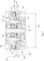
- Eine Abdichtungsanordnung (100) zum Abdichten einer Wellen(150)-Durchgangsöffnung (141), die Folgendes beinhaltet:eine drehbare Motorwelle (150) mit mindestens einem Lager (161), das von mindestens einem Lagerträger (170) getragen wird,eine Motorplatte (140) mit einer Durchgangsöffnung (141) für die Motorwelle (150) mit dem mindestens einen Lager (161),eine Dichtung (110), die einen ersten Abdichtungsabschnitt (111) und einen zweiten Abdichtungsabschnitt (112) aufweist,wobei der erste Abdichtungsabschnitt (111) zwischen mindestens einem Abschnitt einer äußeren peripheren Oberfläche des mindestens einen Lagers (161) und einem Abschnitt des Lagerträgers (170) angeordnet ist; undsich der zweite Abdichtungsabschnitt (112) in einer von der Motorwelle (150) weg weisenden Richtung radial auswärts erstreckt; wobei der zweite Abdichtungsabschnitt (112) von einem Rand der Durchgangsöffnung (141) beabstandet ist; und der zweite Abdichtungsabschnitt (112) gegen radiale und axiale Verschiebung auf der Motorplatte (140) durch ein Fixiermittel fixiert ist, das eine Befestigungskomponente (120) ist, die konfiguriert und angeordnet ist, um den zweiten Abdichtungsabschnitt (112) auf der Motorplatte (140) zu fixieren, und konfiguriert ist, um einen Formschluss und/oder einen Reibschluss zwischen dem zweiten Abdichtungsabschnitt (112) und der Motorplatte (140) zu erzeugen,dadurch gekennzeichnet, dassdie Motorplatte einen oder mehrere vorstehende Abschnitte (142) und/oder eine oder mehrere Einkerbungen zum Verbinden des zweiten Abdichtungsabschnitts (112) und der Befestigungskomponente via Form- und/oder Reibschluss beinhaltet.
- Abdichtungsanordnung (100) gemäß Anspruch 1, wobei der eine oder die mehreren vorstehenden Abschnitte (142) und/oder die eine oder die mehreren Einkerbungen der Motorplatte konfiguriert sind, um die Dichtung (110) und/oder die Befestigungskomponente (120) zu zentrieren.
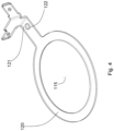
- Abdichtungsanordnung (100) gemäß Anspruch 2, wobei die Befestigungskomponente (120) elektrisch leitend ist und einen Schutzkontakt (121) beinhaltet und/oder so angeordnet ist, dass sie sich zum Befestigen einer Abdeckung eines Motors radial auswärts erstreckt, wobei der Schutzkontakt (121) der Befestigungskomponente (120) optional via mindestens zwei vorstehende Abschnitte (142) in einer oder mehreren vorgegebenen Richtungen ausgerichtet sein kann.
- Abdichtungsanordnung (100) gemäß einem der vorhergehenden Ansprüche, wobei die Dichtung (110) einen dritten Abdichtungsabschnitt (113) beinhaltet, der zwischen dem ersten Abdichtungsabschnitt (111) und dem zweiten Abdichtungsabschnitt (112) liegt, wobei der dritte Abdichtungsabschnitt (113) mindestens eine bogenförmige Form aufweist und radial einwärts von dem zweiten Abdichtungsabschnitt (112) eingerichtet ist.
- Abdichtungsanordnung (100) gemäß Anspruch 4, wobei sich der dritte Abdichtungsabschnitt (113) in die Durchgangsöffnung (141) erstreckt und von dem zweiten Abdichtungsabschnitt (112) via die Durchgangsöffnung (141) durch die Motorplatte (140) durchgeht, wobei der dritte Abdichtungsabschnitt (113) ferner so konfiguriert und angeordnet ist, dass er gerade ist und/oder nach dem Durchgehen durch die Motorplatte (140) eine andere Krümmung aufweist, um sich zu dem ersten Abdichtungsabschnitt (111) zu erstrecken.
- Abdichtungsanordnung (100) gemäß einem der vorhergehenden Ansprüche, wobei der erste Abdichtungsabschnitt (111) im Wesentlichen axial zwischen dem Abschnitt der äußeren peripheren Oberfläche des mindestens einen Lagers (161) und dem Abschnitt des Lagerträgers (170) angeordnet ist und/oder wobei der erste Abdichtungsabschnitt (111) einen im Wesentlichen L-förmigen Querschnitt aufweist, der an seinem radial einwärtigen Ende ein im Wesentlichen horizontales Dichtungselement (116) zur sicheren Passung zwischen gegenüberliegenden Abdichtungsoberflächen des Lagerträgers (170) und eines von dem Lager (161) oder einer Unterlegscheibe (162) aufweist.
- Abdichtungsanordnung (100) gemäß einem der vorhergehenden Ansprüche, wobei die Dichtung (100) elastisch ist.
- Abdichtungsanordnung (100) gemäß einem der vorhergehenden Ansprüche, wobei der zweite Abdichtungsabschnitt (112) eine ringförmige Verbreiterung (114) entlang oder in der Nähe eines äußeren Umfangs des zweiten Abdichtungsabschnitts (112) beinhaltet.
- Abdichtungsanordnung (100) gemäß einem der vorhergehenden Ansprüche, wobei die Motorwelle (150) einen Rotor (151) umfasst, der betreibbar ist, um die Motorwelle (150) zu drehen, und der zweite Abdichtungsabschnitt (112) an einer dem Rotor (151) zugewandten Seite der Motorplatte (140) fixiert ist.
- Abdichtungsanordnung (100) gemäß einem der vorhergehenden Ansprüche, wobei die Abdichtung (110) um eine Achse (115) rotationssymmetrisch ist, wobei sich der erste Abdichtungsabschnitt (111) ferner in einem ersten Radius (R111) von der Achse (115) befindet und sich der zweite Abdichtungsabschnitt (112) in einem zweiten Radius (R112) von der Achse (115) befindet und der zweite Radius (R112) größer als der erste Radius (R111) ist und wobei der erste Radius (R111) von der Motorwelle beabstandet ist.
- Ein Verfahren zum Zusammensetzen einer Abdichtungsanordnung (100), das die folgenden Verfahrensschritte beinhaltet:Bereitstellen einer Motorplatte (140) mit einer Durchgangsöffnung (141);Einführen einer Dichtung (110), die einen ersten Abdichtungsabschnitt (111) und einen zweiten Abdichtungsabschnitt (112) beinhaltet, mindestens teilweise in die Durchgangsöffnung (141), sodass der zweite Abdichtungsabschnitt (112) von einem Rand der Durchgangsöffnung (141) beabstandet ist; undFixieren des zweiten Abdichtungsabschnitts (112) an der Motorplatte (140), dadurch gekennzeichnet, dass die Motorplatte (140) einen oder mehrere vorstehende Abschnitte (142) und/oder eine oder mehrere Einkerbungen umfasst und wobei der Schritt des Fixierens des zweiten Abdichtungsabschnitts (112) an der Motorplatte (140) Folgendes umfasst:Positionieren des zweiten Abdichtungsabschnitts (112) neben einer radial einwärts gewandten Seite des einen oder der mehreren vorstehenden Abschnitte (142) der Motorplatte (140);Positionieren einer Befestigungskomponente (120) auf dem zweiten Abdichtungsabschnitt (112), sodass der zweite Abdichtungsabschnitt (112) zwischen der Motorplatte (140) und der Befestigungskomponente (120) angeordnet ist; undDrücken eines Abschnitts des einen oder der mehreren vorstehenden Abschnitte (142) auf die Befestigungskomponente (120), sodass die Befestigungskomponente (120) und der zweite Abdichtungsabschnitt (112) via einen Formschluss und/oder einen Reibschluss gehalten werden.
- Ein Verfahren zum Verifizieren der Dichtheit der Abdichtungsanordnung (100) gemäß einem der Ansprüche 1 bis 10 und ferner beinhaltend einen Motor, der mit einem Ende der Motorwelle (150) in einem Motorgehäuse gekoppelt ist, und einen Lüfter, der mit einem anderen Ende der Motorwelle in einem Lüftergehäuse gekoppelt ist; wobei das Verfahren die folgenden Verfahrensschritte beinhaltet:Bereitstellen mindestens eines abgedichteten Lagers (161) oder Abdichten des mindestens einen Lagers (161);Erhöhen eines Drucks und/oder Bereitstellen eines Prüfgases, das aus inerten Gasen, Stickstoff, Edelgasen oder einer Kombination davon ausgewählt ist, vorzugsweise auf der Lüfterseite der Abdichtungsanordnung (100); undErmitteln von einem oder mehreren von einer Druckänderung im Zeitablauf, einer Flussrate oder eines Prüfgases, um die Dichtheit der Abdichtungsanordnung zu verifizieren.
Priority Applications (3)
| Application Number | Priority Date | Filing Date | Title |
|---|---|---|---|
| EP21169027.6A EP4074979B1 (de) | 2021-04-16 | 2021-04-16 | Dichtungsanordnung für eine wellendurchgangsöffnung eines lüfters |
| US18/555,579 US12480517B2 (en) | 2021-04-16 | 2022-04-04 | Sealing assembly for a shaft passage opening for a fan |
| PCT/EP2022/058902 WO2022218742A1 (en) | 2021-04-16 | 2022-04-04 | Sealing assembly for a shaft passage opening for a fan |
Applications Claiming Priority (1)
| Application Number | Priority Date | Filing Date | Title |
|---|---|---|---|
| EP21169027.6A EP4074979B1 (de) | 2021-04-16 | 2021-04-16 | Dichtungsanordnung für eine wellendurchgangsöffnung eines lüfters |
Publications (2)
| Publication Number | Publication Date |
|---|---|
| EP4074979A1 EP4074979A1 (de) | 2022-10-19 |
| EP4074979B1 true EP4074979B1 (de) | 2024-12-18 |
Family
ID=75581404
Family Applications (1)
| Application Number | Title | Priority Date | Filing Date |
|---|---|---|---|
| EP21169027.6A Active EP4074979B1 (de) | 2021-04-16 | 2021-04-16 | Dichtungsanordnung für eine wellendurchgangsöffnung eines lüfters |
Country Status (3)
| Country | Link |
|---|---|
| US (1) | US12480517B2 (de) |
| EP (1) | EP4074979B1 (de) |
| WO (1) | WO2022218742A1 (de) |
Family Cites Families (4)
| Publication number | Priority date | Publication date | Assignee | Title |
|---|---|---|---|---|
| US3997805A (en) * | 1974-04-08 | 1976-12-14 | General Electric Company | Resilient electric motor bearing seal |
| US8303184B1 (en) * | 2008-06-11 | 2012-11-06 | AquaMotion, Inc. | Motor pump bearing |
| TWI539082B (zh) * | 2013-12-02 | 2016-06-21 | 建準電機工業股份有限公司 | 氣體鼓風裝置 |
| US10989304B1 (en) * | 2020-07-27 | 2021-04-27 | Teadit N.A., Inc. | Compression packing |
-
2021
- 2021-04-16 EP EP21169027.6A patent/EP4074979B1/de active Active
-
2022
- 2022-04-04 WO PCT/EP2022/058902 patent/WO2022218742A1/en not_active Ceased
- 2022-04-04 US US18/555,579 patent/US12480517B2/en active Active
Also Published As
| Publication number | Publication date |
|---|---|
| EP4074979A1 (de) | 2022-10-19 |
| US20240200566A1 (en) | 2024-06-20 |
| US12480517B2 (en) | 2025-11-25 |
| WO2022218742A1 (en) | 2022-10-20 |
Similar Documents
| Publication | Publication Date | Title |
|---|---|---|
| EP2878827B1 (de) | Gaslüfter | |
| US4365816A (en) | Self-damping bellows seal assembly | |
| US9038987B2 (en) | Flap assembly, in particular exhaust gas flap assembly | |
| US5947479A (en) | Mechanical seal with flexible metal diaphragm | |
| JP7600564B2 (ja) | モータ、および駆動装置 | |
| US10069382B2 (en) | Earthing device | |
| CN114079346B (zh) | 电动机器 | |
| US11221022B2 (en) | Turbine housing and turbocharger including the same | |
| CN104612999A (zh) | 具有改进的密封组件的机械密封件 | |
| JP2014066174A (ja) | 位置決め装置、及びこれを備えている回転式流体機械 | |
| EP2511483B1 (de) | Dichtungsmechanismus mittels akkordeon-bälgen und dampfturbine mit besagtem dichtmechanismus | |
| EP3608522B1 (de) | Turbolader | |
| EP4074979B1 (de) | Dichtungsanordnung für eine wellendurchgangsöffnung eines lüfters | |
| US10036390B2 (en) | Pump unit | |
| US6028379A (en) | Arrangement for the vibration isolating mounting of an electric motor | |
| WO2016143657A1 (ja) | 分割型ブラシシール装置、ブラシシール片及び分割型ブラシシール装置の組立方法 | |
| JP4520707B2 (ja) | 孔内にパイプを接続するための密封装置 | |
| CN118302624A (zh) | 密封结构 | |
| US20040227304A1 (en) | Sealing Ring | |
| US20230235816A1 (en) | Drive having a housing, adapter plate, and cover hood | |
| EP1904769B1 (de) | Vorrichtung für eine drehstopfbuchsendichtung | |
| CN214888845U (zh) | 壳体转轴转动密封机构 | |
| US10533664B1 (en) | Rotary vane radial seal assembly system | |
| CN113474563A (zh) | 具有可变可调节的插头连接器出口的风扇组件 | |
| JP7811302B1 (ja) | 封止構造 |
Legal Events
| Date | Code | Title | Description |
|---|---|---|---|
| PUAI | Public reference made under article 153(3) epc to a published international application that has entered the european phase |
Free format text: ORIGINAL CODE: 0009012 |
|
| STAA | Information on the status of an ep patent application or granted ep patent |
Free format text: STATUS: THE APPLICATION HAS BEEN PUBLISHED |
|
| AK | Designated contracting states |
Kind code of ref document: A1 Designated state(s): AL AT BE BG CH CY CZ DE DK EE ES FI FR GB GR HR HU IE IS IT LI LT LU LV MC MK MT NL NO PL PT RO RS SE SI SK SM TR |
|
| STAA | Information on the status of an ep patent application or granted ep patent |
Free format text: STATUS: REQUEST FOR EXAMINATION WAS MADE |
|
| 17P | Request for examination filed |
Effective date: 20230401 |
|
| RBV | Designated contracting states (corrected) |
Designated state(s): AL AT BE BG CH CY CZ DE DK EE ES FI FR GB GR HR HU IE IS IT LI LT LU LV MC MK MT NL NO PL PT RO RS SE SI SK SM TR |
|
| P01 | Opt-out of the competence of the unified patent court (upc) registered |
Effective date: 20230827 |
|
| GRAP | Despatch of communication of intention to grant a patent |
Free format text: ORIGINAL CODE: EPIDOSNIGR1 |
|
| STAA | Information on the status of an ep patent application or granted ep patent |
Free format text: STATUS: GRANT OF PATENT IS INTENDED |
|
| INTG | Intention to grant announced |
Effective date: 20240729 |
|
| GRAS | Grant fee paid |
Free format text: ORIGINAL CODE: EPIDOSNIGR3 |
|
| GRAA | (expected) grant |
Free format text: ORIGINAL CODE: 0009210 |
|
| STAA | Information on the status of an ep patent application or granted ep patent |
Free format text: STATUS: THE PATENT HAS BEEN GRANTED |
|
| AK | Designated contracting states |
Kind code of ref document: B1 Designated state(s): AL AT BE BG CH CY CZ DE DK EE ES FI FR GB GR HR HU IE IS IT LI LT LU LV MC MK MT NL NO PL PT RO RS SE SI SK SM TR |
|
| REG | Reference to a national code |
Ref country code: CH Ref legal event code: EP |
|
| REG | Reference to a national code |
Ref country code: DE Ref legal event code: R096 Ref document number: 602021023431 Country of ref document: DE |
|
| REG | Reference to a national code |
Ref country code: IE Ref legal event code: FG4D |
|
| REG | Reference to a national code |
Ref country code: NL Ref legal event code: FP |
|
| REG | Reference to a national code |
Ref country code: LT Ref legal event code: MG9D |
|
| PG25 | Lapsed in a contracting state [announced via postgrant information from national office to epo] |
Ref country code: HR Free format text: LAPSE BECAUSE OF FAILURE TO SUBMIT A TRANSLATION OF THE DESCRIPTION OR TO PAY THE FEE WITHIN THE PRESCRIBED TIME-LIMIT Effective date: 20241218 |
|
| PG25 | Lapsed in a contracting state [announced via postgrant information from national office to epo] |
Ref country code: FI Free format text: LAPSE BECAUSE OF FAILURE TO SUBMIT A TRANSLATION OF THE DESCRIPTION OR TO PAY THE FEE WITHIN THE PRESCRIBED TIME-LIMIT Effective date: 20241218 |
|
| PG25 | Lapsed in a contracting state [announced via postgrant information from national office to epo] |
Ref country code: BG Free format text: LAPSE BECAUSE OF FAILURE TO SUBMIT A TRANSLATION OF THE DESCRIPTION OR TO PAY THE FEE WITHIN THE PRESCRIBED TIME-LIMIT Effective date: 20241218 |
|
| PG25 | Lapsed in a contracting state [announced via postgrant information from national office to epo] |
Ref country code: NO Free format text: LAPSE BECAUSE OF FAILURE TO SUBMIT A TRANSLATION OF THE DESCRIPTION OR TO PAY THE FEE WITHIN THE PRESCRIBED TIME-LIMIT Effective date: 20250318 |
|
| PG25 | Lapsed in a contracting state [announced via postgrant information from national office to epo] |
Ref country code: GR Free format text: LAPSE BECAUSE OF FAILURE TO SUBMIT A TRANSLATION OF THE DESCRIPTION OR TO PAY THE FEE WITHIN THE PRESCRIBED TIME-LIMIT Effective date: 20250319 Ref country code: LV Free format text: LAPSE BECAUSE OF FAILURE TO SUBMIT A TRANSLATION OF THE DESCRIPTION OR TO PAY THE FEE WITHIN THE PRESCRIBED TIME-LIMIT Effective date: 20241218 |
|
| PG25 | Lapsed in a contracting state [announced via postgrant information from national office to epo] |
Ref country code: RS Free format text: LAPSE BECAUSE OF FAILURE TO SUBMIT A TRANSLATION OF THE DESCRIPTION OR TO PAY THE FEE WITHIN THE PRESCRIBED TIME-LIMIT Effective date: 20250318 |
|
| PGFP | Annual fee paid to national office [announced via postgrant information from national office to epo] |
Ref country code: NL Payment date: 20250424 Year of fee payment: 5 |
|
| REG | Reference to a national code |
Ref country code: AT Ref legal event code: MK05 Ref document number: 1752419 Country of ref document: AT Kind code of ref document: T Effective date: 20241218 |
|
| PG25 | Lapsed in a contracting state [announced via postgrant information from national office to epo] |
Ref country code: SM Free format text: LAPSE BECAUSE OF FAILURE TO SUBMIT A TRANSLATION OF THE DESCRIPTION OR TO PAY THE FEE WITHIN THE PRESCRIBED TIME-LIMIT Effective date: 20241218 |
|
| PG25 | Lapsed in a contracting state [announced via postgrant information from national office to epo] |
Ref country code: PL Free format text: LAPSE BECAUSE OF FAILURE TO SUBMIT A TRANSLATION OF THE DESCRIPTION OR TO PAY THE FEE WITHIN THE PRESCRIBED TIME-LIMIT Effective date: 20241218 |
|
| PGFP | Annual fee paid to national office [announced via postgrant information from national office to epo] |
Ref country code: DE Payment date: 20250528 Year of fee payment: 5 |
|
| PG25 | Lapsed in a contracting state [announced via postgrant information from national office to epo] |
Ref country code: ES Free format text: LAPSE BECAUSE OF FAILURE TO SUBMIT A TRANSLATION OF THE DESCRIPTION OR TO PAY THE FEE WITHIN THE PRESCRIBED TIME-LIMIT Effective date: 20241218 |
|
| PGFP | Annual fee paid to national office [announced via postgrant information from national office to epo] |
Ref country code: GB Payment date: 20250422 Year of fee payment: 5 |
|
| PG25 | Lapsed in a contracting state [announced via postgrant information from national office to epo] |
Ref country code: IS Free format text: LAPSE BECAUSE OF FAILURE TO SUBMIT A TRANSLATION OF THE DESCRIPTION OR TO PAY THE FEE WITHIN THE PRESCRIBED TIME-LIMIT Effective date: 20250418 |
|
| PG25 | Lapsed in a contracting state [announced via postgrant information from national office to epo] |
Ref country code: PT Free format text: LAPSE BECAUSE OF FAILURE TO SUBMIT A TRANSLATION OF THE DESCRIPTION OR TO PAY THE FEE WITHIN THE PRESCRIBED TIME-LIMIT Effective date: 20250421 |
|
| PG25 | Lapsed in a contracting state [announced via postgrant information from national office to epo] |
Ref country code: EE Free format text: LAPSE BECAUSE OF FAILURE TO SUBMIT A TRANSLATION OF THE DESCRIPTION OR TO PAY THE FEE WITHIN THE PRESCRIBED TIME-LIMIT Effective date: 20241218 |
|
| PGFP | Annual fee paid to national office [announced via postgrant information from national office to epo] |
Ref country code: FR Payment date: 20250424 Year of fee payment: 5 |
|
| PG25 | Lapsed in a contracting state [announced via postgrant information from national office to epo] |
Ref country code: AT Free format text: LAPSE BECAUSE OF FAILURE TO SUBMIT A TRANSLATION OF THE DESCRIPTION OR TO PAY THE FEE WITHIN THE PRESCRIBED TIME-LIMIT Effective date: 20241218 Ref country code: RO Free format text: LAPSE BECAUSE OF FAILURE TO SUBMIT A TRANSLATION OF THE DESCRIPTION OR TO PAY THE FEE WITHIN THE PRESCRIBED TIME-LIMIT Effective date: 20241218 |
|
| PG25 | Lapsed in a contracting state [announced via postgrant information from national office to epo] |
Ref country code: SK Free format text: LAPSE BECAUSE OF FAILURE TO SUBMIT A TRANSLATION OF THE DESCRIPTION OR TO PAY THE FEE WITHIN THE PRESCRIBED TIME-LIMIT Effective date: 20241218 |
|
| PG25 | Lapsed in a contracting state [announced via postgrant information from national office to epo] |
Ref country code: CZ Free format text: LAPSE BECAUSE OF FAILURE TO SUBMIT A TRANSLATION OF THE DESCRIPTION OR TO PAY THE FEE WITHIN THE PRESCRIBED TIME-LIMIT Effective date: 20241218 |
|
| PG25 | Lapsed in a contracting state [announced via postgrant information from national office to epo] |
Ref country code: IT Free format text: LAPSE BECAUSE OF FAILURE TO SUBMIT A TRANSLATION OF THE DESCRIPTION OR TO PAY THE FEE WITHIN THE PRESCRIBED TIME-LIMIT Effective date: 20241218 |
|
| PG25 | Lapsed in a contracting state [announced via postgrant information from national office to epo] |
Ref country code: SE Free format text: LAPSE BECAUSE OF FAILURE TO SUBMIT A TRANSLATION OF THE DESCRIPTION OR TO PAY THE FEE WITHIN THE PRESCRIBED TIME-LIMIT Effective date: 20241218 |
|
| REG | Reference to a national code |
Ref country code: DE Ref legal event code: R097 Ref document number: 602021023431 Country of ref document: DE |
|
| PG25 | Lapsed in a contracting state [announced via postgrant information from national office to epo] |
Ref country code: DK Free format text: LAPSE BECAUSE OF FAILURE TO SUBMIT A TRANSLATION OF THE DESCRIPTION OR TO PAY THE FEE WITHIN THE PRESCRIBED TIME-LIMIT Effective date: 20241218 |
|
| PLBE | No opposition filed within time limit |
Free format text: ORIGINAL CODE: 0009261 |
|
| STAA | Information on the status of an ep patent application or granted ep patent |
Free format text: STATUS: NO OPPOSITION FILED WITHIN TIME LIMIT |
|
| REG | Reference to a national code |
Ref country code: CH Ref legal event code: L10 Free format text: ST27 STATUS EVENT CODE: U-0-0-L10-L00 (AS PROVIDED BY THE NATIONAL OFFICE) Effective date: 20251029 |
|
| REG | Reference to a national code |
Ref country code: CH Ref legal event code: H13 Free format text: ST27 STATUS EVENT CODE: U-0-0-H10-H13 (AS PROVIDED BY THE NATIONAL OFFICE) Effective date: 20251125 |
|
| 26N | No opposition filed |
Effective date: 20250919 |
|
| PG25 | Lapsed in a contracting state [announced via postgrant information from national office to epo] |
Ref country code: LU Free format text: LAPSE BECAUSE OF NON-PAYMENT OF DUE FEES Effective date: 20250416 |
|
| PG25 | Lapsed in a contracting state [announced via postgrant information from national office to epo] |
Ref country code: MC Free format text: LAPSE BECAUSE OF FAILURE TO SUBMIT A TRANSLATION OF THE DESCRIPTION OR TO PAY THE FEE WITHIN THE PRESCRIBED TIME-LIMIT Effective date: 20241218 |
|
| REG | Reference to a national code |
Ref country code: BE Ref legal event code: MM Effective date: 20250430 |
|
| PG25 | Lapsed in a contracting state [announced via postgrant information from national office to epo] |
Ref country code: BE Free format text: LAPSE BECAUSE OF NON-PAYMENT OF DUE FEES Effective date: 20250430 |
|
| PG25 | Lapsed in a contracting state [announced via postgrant information from national office to epo] |
Ref country code: CH Free format text: LAPSE BECAUSE OF NON-PAYMENT OF DUE FEES Effective date: 20250430 |
|
| REG | Reference to a national code |
Ref country code: CH Ref legal event code: Y10 Free format text: ST27 STATUS EVENT CODE: U-0-0-Y10-Y00 (AS PROVIDED BY THE NATIONAL OFFICE) Effective date: 20260305 |
|
| PG25 | Lapsed in a contracting state [announced via postgrant information from national office to epo] |
Ref country code: IE Free format text: LAPSE BECAUSE OF NON-PAYMENT OF DUE FEES Effective date: 20250416 |