EP4074966B1 - Tank und anordnung mit einem tank - Google Patents
Tank und anordnung mit einem tank Download PDFInfo
- Publication number
- EP4074966B1 EP4074966B1 EP22167628.1A EP22167628A EP4074966B1 EP 4074966 B1 EP4074966 B1 EP 4074966B1 EP 22167628 A EP22167628 A EP 22167628A EP 4074966 B1 EP4074966 B1 EP 4074966B1
- Authority
- EP
- European Patent Office
- Prior art keywords
- tank
- chamber
- limb
- oil
- space
- Prior art date
- Legal status (The legal status is an assumption and is not a legal conclusion. Google has not performed a legal analysis and makes no representation as to the accuracy of the status listed.)
- Active
Links
Images



Classifications
-
- F—MECHANICAL ENGINEERING; LIGHTING; HEATING; WEAPONS; BLASTING
- F15—FLUID-PRESSURE ACTUATORS; HYDRAULICS OR PNEUMATICS IN GENERAL
- F15B—SYSTEMS ACTING BY MEANS OF FLUIDS IN GENERAL; FLUID-PRESSURE ACTUATORS, e.g. SERVOMOTORS; DETAILS OF FLUID-PRESSURE SYSTEMS, NOT OTHERWISE PROVIDED FOR
- F15B1/00—Installations or systems with accumulators; Supply reservoir or sump assemblies
- F15B1/26—Supply reservoir or sump assemblies
-
- F—MECHANICAL ENGINEERING; LIGHTING; HEATING; WEAPONS; BLASTING
- F04—POSITIVE - DISPLACEMENT MACHINES FOR LIQUIDS; PUMPS FOR LIQUIDS OR ELASTIC FLUIDS
- F04B—POSITIVE-DISPLACEMENT MACHINES FOR LIQUIDS; PUMPS
- F04B23/00—Pumping installations or systems
- F04B23/02—Pumping installations or systems having reservoirs
- F04B23/025—Pumping installations or systems having reservoirs the pump being located directly adjacent the reservoir
- F04B23/028—Pumping installations or systems having reservoirs the pump being located directly adjacent the reservoir the pump being mounted on top of the reservoir
-
- F—MECHANICAL ENGINEERING; LIGHTING; HEATING; WEAPONS; BLASTING
- F15—FLUID-PRESSURE ACTUATORS; HYDRAULICS OR PNEUMATICS IN GENERAL
- F15B—SYSTEMS ACTING BY MEANS OF FLUIDS IN GENERAL; FLUID-PRESSURE ACTUATORS, e.g. SERVOMOTORS; DETAILS OF FLUID-PRESSURE SYSTEMS, NOT OTHERWISE PROVIDED FOR
- F15B21/00—Common features of fluid actuator systems; Fluid-pressure actuator systems or details thereof, not covered by any other group of this subclass
- F15B21/04—Special measures taken in connection with the properties of the fluid
- F15B21/042—Controlling the temperature of the fluid
- F15B21/0423—Cooling
-
- F—MECHANICAL ENGINEERING; LIGHTING; HEATING; WEAPONS; BLASTING
- F15—FLUID-PRESSURE ACTUATORS; HYDRAULICS OR PNEUMATICS IN GENERAL
- F15B—SYSTEMS ACTING BY MEANS OF FLUIDS IN GENERAL; FLUID-PRESSURE ACTUATORS, e.g. SERVOMOTORS; DETAILS OF FLUID-PRESSURE SYSTEMS, NOT OTHERWISE PROVIDED FOR
- F15B21/00—Common features of fluid actuator systems; Fluid-pressure actuator systems or details thereof, not covered by any other group of this subclass
- F15B21/04—Special measures taken in connection with the properties of the fluid
- F15B21/044—Removal or measurement of undissolved gas, e.g. de-aeration, venting or bleeding
-
- F—MECHANICAL ENGINEERING; LIGHTING; HEATING; WEAPONS; BLASTING
- F15—FLUID-PRESSURE ACTUATORS; HYDRAULICS OR PNEUMATICS IN GENERAL
- F15B—SYSTEMS ACTING BY MEANS OF FLUIDS IN GENERAL; FLUID-PRESSURE ACTUATORS, e.g. SERVOMOTORS; DETAILS OF FLUID-PRESSURE SYSTEMS, NOT OTHERWISE PROVIDED FOR
- F15B21/00—Common features of fluid actuator systems; Fluid-pressure actuator systems or details thereof, not covered by any other group of this subclass
- F15B21/04—Special measures taken in connection with the properties of the fluid
- F15B21/041—Removal or measurement of solid or liquid contamination, e.g. filtering
-
- F—MECHANICAL ENGINEERING; LIGHTING; HEATING; WEAPONS; BLASTING
- F15—FLUID-PRESSURE ACTUATORS; HYDRAULICS OR PNEUMATICS IN GENERAL
- F15B—SYSTEMS ACTING BY MEANS OF FLUIDS IN GENERAL; FLUID-PRESSURE ACTUATORS, e.g. SERVOMOTORS; DETAILS OF FLUID-PRESSURE SYSTEMS, NOT OTHERWISE PROVIDED FOR
- F15B21/00—Common features of fluid actuator systems; Fluid-pressure actuator systems or details thereof, not covered by any other group of this subclass
- F15B21/04—Special measures taken in connection with the properties of the fluid
- F15B21/042—Controlling the temperature of the fluid
-
- F—MECHANICAL ENGINEERING; LIGHTING; HEATING; WEAPONS; BLASTING
- F15—FLUID-PRESSURE ACTUATORS; HYDRAULICS OR PNEUMATICS IN GENERAL
- F15B—SYSTEMS ACTING BY MEANS OF FLUIDS IN GENERAL; FLUID-PRESSURE ACTUATORS, e.g. SERVOMOTORS; DETAILS OF FLUID-PRESSURE SYSTEMS, NOT OTHERWISE PROVIDED FOR
- F15B2211/00—Circuits for servomotor systems
- F15B2211/20—Fluid pressure source, e.g. accumulator or variable axial piston pump
- F15B2211/205—Systems with pumps
- F15B2211/20507—Type of prime mover
- F15B2211/20515—Electric motor
-
- F—MECHANICAL ENGINEERING; LIGHTING; HEATING; WEAPONS; BLASTING
- F15—FLUID-PRESSURE ACTUATORS; HYDRAULICS OR PNEUMATICS IN GENERAL
- F15B—SYSTEMS ACTING BY MEANS OF FLUIDS IN GENERAL; FLUID-PRESSURE ACTUATORS, e.g. SERVOMOTORS; DETAILS OF FLUID-PRESSURE SYSTEMS, NOT OTHERWISE PROVIDED FOR
- F15B2211/00—Circuits for servomotor systems
- F15B2211/20—Fluid pressure source, e.g. accumulator or variable axial piston pump
- F15B2211/205—Systems with pumps
- F15B2211/2053—Type of pump
-
- F—MECHANICAL ENGINEERING; LIGHTING; HEATING; WEAPONS; BLASTING
- F15—FLUID-PRESSURE ACTUATORS; HYDRAULICS OR PNEUMATICS IN GENERAL
- F15B—SYSTEMS ACTING BY MEANS OF FLUIDS IN GENERAL; FLUID-PRESSURE ACTUATORS, e.g. SERVOMOTORS; DETAILS OF FLUID-PRESSURE SYSTEMS, NOT OTHERWISE PROVIDED FOR
- F15B2211/00—Circuits for servomotor systems
- F15B2211/60—Circuit components or control therefor
- F15B2211/615—Filtering means
-
- F—MECHANICAL ENGINEERING; LIGHTING; HEATING; WEAPONS; BLASTING
- F15—FLUID-PRESSURE ACTUATORS; HYDRAULICS OR PNEUMATICS IN GENERAL
- F15B—SYSTEMS ACTING BY MEANS OF FLUIDS IN GENERAL; FLUID-PRESSURE ACTUATORS, e.g. SERVOMOTORS; DETAILS OF FLUID-PRESSURE SYSTEMS, NOT OTHERWISE PROVIDED FOR
- F15B2211/00—Circuits for servomotor systems
- F15B2211/60—Circuit components or control therefor
- F15B2211/62—Cooling or heating means
-
- F—MECHANICAL ENGINEERING; LIGHTING; HEATING; WEAPONS; BLASTING
- F15—FLUID-PRESSURE ACTUATORS; HYDRAULICS OR PNEUMATICS IN GENERAL
- F15B—SYSTEMS ACTING BY MEANS OF FLUIDS IN GENERAL; FLUID-PRESSURE ACTUATORS, e.g. SERVOMOTORS; DETAILS OF FLUID-PRESSURE SYSTEMS, NOT OTHERWISE PROVIDED FOR
- F15B2211/00—Circuits for servomotor systems
- F15B2211/60—Circuit components or control therefor
- F15B2211/63—Electronic controllers
- F15B2211/6303—Electronic controllers using input signals
Definitions
- the invention relates to a tank for a cooling liquid or for a pressure medium, in particular for an oil, according to the preamble of claim 1. Furthermore, the invention relates to an arrangement with a tank and with a hydraulic block.
- a tank for a hydraulic unit serves to store a hydraulic fluid.
- the tank has an upper inlet connection and a drain connection arranged underneath.
- Guide walls are formed between the connections, which guide a flow of hydraulic fluid from the inlet connection to the drain connection.
- the flow guide is designed in such a way that it has at least two 180° flow bends for cooling and calming the hydraulic fluid and for avoiding dead zones.
- the invention is based on the object of creating a tank and arrangement with a tank, which has a comparatively small tank volume, improved degassing and improved climate management.
- a tank for oil has a tank space for storing the oil.
- the tank space has a return opening and a suction opening for the oil.
- the tank space is U-shaped with a first space leg and a second space leg. The space legs are connected via a transverse space leg of the tank space.
- the tank space has two space legs which extend parallel to one another or at an angle to one another and whose end sides are connected via a transverse space leg.
- the return opening is connected to the first space leg and the suction opening is connected to the second space leg. Liquid can thus flow into the tank space via the return opening and flow via the first space leg to the second space leg. The liquid can then exit the tank space again via the suction opening.
- the legs are arranged horizontally.
- the transverse space leg is delimited by two outer wall sections of an outer side wall.
- An outer wall section is then arranged adjacent to the first space leg and the further outer wall section adjacent to the second space leg.
- At least one of the outer wall sections extends, viewed in cross-section, in particular transversely to the top-bottom direction, obliquely with respect to a longitudinal axis of the adjacent space leg.
- This outer wall section extends obliquely in such a way that the tank has a bevelled corner for diverting the flow of the oil from the first space leg into the second space leg. If a free space is provided, at least one obliquely arranged outer wall section extends towards the free space.
- a partition wall for example in a sheet metal tank
- the obliquely formed outer wall section points towards the partition wall.
- both outer wall sections are arranged at an angle.
- the two outer wall sections are arranged, for example, in a V-shape or approximately in a V-shape relative to one another.
- the outer wall sections are provided on the front side of the tank, whereby the tank, viewed from the outside, is then in the area of the transverse space leg can taper.
- the diagonally arranged outer wall sections can prevent waves and turbulence in the liquid. In other words, bevelled side walls serve to prevent waves and turbulence.
- the outer wall sections are preferably arranged in such a way that they deflect the flow by 90° or approximately 90°. This reduces or largely avoids back pressure, which leads to a reduction in wave movement and turbulence.
- the tank has bevelled corners to deflect the flow from one space leg to the other space leg. It has been shown that the horizontal arrangement of the legs can reduce the tank volume, while at the same time improving degassing and climate management.
- the U-shaped flow guidance enables improved oil utilization. Stagnant areas or dead volumes in the tank space are minimized, which is why channel formation with warm oil from the return to the suction line is prevented or at least reduced, since the oil has to flow through all areas in the tank space.
- the two-leg design with the two space legs means that at least the second space leg can serve as a fluid zone and calm the oil in a simple way, as it is separated from the turbulent return area. It has been shown that the horizontal shape of the U-shaped legs improves degassing of the oil due to the active deflection of the oil flow compared to the state of the art. In addition, climate management in the tank is improved, as it has been shown that the described design almost completely circulates the oil during operation. This ensures that the oil is well distributed in the tank and the temperature of the oil can be measured more accurately, as temperature differences in the oil are comparatively small.
- the legs extend approximately parallel to the earth's surface. This means that there is preferably no gradient from the inlet to the outlet. This means that the legs can extend transversely to the direction of gravity.
- the arrangement of the tank in space can vary from a position of the vehicle.
- the legs can extend approximately parallel to a chassis plane.
- the tank can be made of plastic in a simple manner. Rotational molding has proven to be an extremely cost-effective method for producing the tank.
- the U-shaped design of the tank is advantageously suited for this. If necessary, it is conceivable to produce the tank using a plastic injection molding process.
- the tank can be designed as a sheet metal tank. Walls can then be connected in a materially bonded manner, for example by welding, or at least partially by bends.
- the first space leg is preferably delimited by a leg base.
- a diffuser projection can be formed and/or integrated on the leg base, which extends into the space leg.
- the diffuser projection can advantageously split the liquid flow in the tank space, so that in particular no so-called sloshing occurs.
- the diffuser projection is preferably formed opposite the return opening, which is arranged in particular at the top. Alternatively or additionally, it is conceivable to form a further diffuser projection on the second space leg on the leg base, in particular opposite the suction line, in order to guide the flow better.
- the direction of the diffuser projection opposite the return opening or return line has the advantage that the greatest volume flow can prevail here when liquid flows into the tank space.
- the diffuser projection can be provided in an axial geometric extension of the return opening or the return line.
- the return opening is preferably arranged above the tank space.
- the return opening can, for example, be designed in such a way that liquid flows into the tank space in the direction of gravity.
- the diffuser projection preferably tapers inwards in the direction away from the leg base. It can, for example, be conical or frustoconical or pyramidal or rotationally symmetrical. Viewed from the outside, it is conceivable that the diffuser projection is concave.
- a wall thickness of the diffuser projection corresponds, for example, to a wall thickness of the leg base.
- a wall thickness of the diffuser projection is formed in the tank wall or in the a conical geometry is integrated into the tank bottom, which ideally splits the oil flow in the tank.
- a longitudinal axis of the diffuser projection is preferably coaxial or approximately coaxial to a longitudinal axis of the return opening. "Approximately” can mean that tolerances are permitted so that the general function of the diffuser projection is possible.
- a flow direction of the liquid emerging from the return opening points towards the diffuser projection.
- the flow direction and a longitudinal axis of the diffuser projection are, for example, arranged at least approximately parallel to one another.
- the return opening can be arranged above the diffuser projection.
- the legs are preferably delimited by a side wall of the tank.
- the tank can be designed as a U-shaped trough. It would also be conceivable to design the tank as a trough that is divided into two by an inner wall, the inner wall having a through-opening in order to connect the spatial legs separated from one another by the inner wall, in order to achieve an approximately U-shaped design.
- a tank clearance is formed between the first and second space legs.
- This can be delimited by a first and a second side wall section.
- These side wall sections can in turn delimit the first and second space legs.
- a transverse side wall section delimiting the transverse space leg can then be provided between the two side wall sections.
- the side wall sections and the transverse side wall section can extend upwards from a tank bottom or from leg bottoms or the leg bottoms.
- the side wall sections and the transverse side wall section are U-shaped and thus form a U-shaped inner wall for the legs.
- the tank free space which is delimited by the side wall sections and the transverse side wall section, can be closed at the top, in particular as seen in the direction of gravity, by an inner cover section of the tank. It is conceivable that the tank free space can be closed downwards, in particular as seen in the direction of gravity, and/or in the direction away from the The transverse space leg is open. The tank free space can thus be closed on the inside and open on the outside, which makes it easy to manufacture.
- the height of the tank free space is preferably less than the height of the tank. This makes it possible for the inner cover section to be flushed if necessary. If necessary, liquid can flow from one space leg over the inner cover section to the other space leg.
- the tank preferably has a tank lid that covers the leg spaces. This is preferably formed in one piece with the tank and produced, for example, by rotational molding. If a free space with an inner lid section is provided, this can be spaced apart from the tank lid. It is also conceivable that the inner lid section is part of the tank lid.
- the legs are delimited by an outer side wall, which is in particular integrally connected to the tank lid and further preferably integrally connected to a tank bottom or the leg bottoms or leg bottoms.
- the outer side wall preferably surrounds the inner side wall sections with the transverse side wall section in such a way that the U-shaped legs are formed.
- the legs are delimited from below by a base wall.
- a base wall This can, for example, be simply U-shaped.
- the outer side wall is then preferably formed in one piece between the tank lid and the base wall.
- the leg bottoms can be part of the base wall.
- the recess can be concave when viewed from the outside and convex when viewed from the inside. It is conceivable that the recess has one or more interruptions.
- the recess supports on the one hand, the flow guidance and on the other hand, it can advantageously lead to a stiffening of the tank, in particular the bottom wall.
- the U-shaped recess preferably extends approximately parallel to the legs. A width of the recess can be smaller than a bottom-side width of the legs.
- the recess is preferably spaced from the walls.
- the outer side wall can have at least one inner transverse rib on one or both space legs. This can extend approximately or exactly in the direction from top to bottom.
- the transverse rib leads in particular to an advantageous stiffening of the tank.
- the mechanical stability of the tank can be improved by using traverse webs.
- the tank lid of the tank preferably has a flange.
- This can be designed in such a way that it can be connected to a hydraulic block directly or via another component.
- the flange preferably has an annular flange surface.
- the flange surface can extend, for example, in a plane, in particular in a plane transverse to the direction of gravity or the top-bottom direction.
- the flange surface preferably comprises a lid opening of the tank lid. Lines for the return and the suction can easily be introduced into the tank via the lid opening.
- Both space legs are preferably accessible via the lid opening. It is conceivable that the two space legs are open at the top via the lid opening, whereby the lid opening can be covered, for example, by a hydraulic block.
- the lid opening can then be designed in such a way that lines of the hydraulic block project over the lid opening into the space legs, in particular exactly or approximately in the direction of gravity or the top-bottom direction.
- the tank has a support frame, by means of which the tank can be secured.
- the support frame can be U-shaped, for example.
- the support frame can be designed in such a way that it is supported on a floor surface or a component.
- an upper side of the tank is firmly connected to the support frame. At least it is conceivable that part of the tank weight or the entire tank weight is carried by the support frame via the top.
- the support frame can reach over the tank and be supported on the floor surface. If the support frame is U-shaped, for example, it is conceivable that the tank is arranged between the frame legs.
- the support frame is fastened to the tank via means via the flange surface of the tank, in particular via a sealing ring arranged on the flange surface. Screw connections, for example, serve as means.
- the support frame can also have a flange section that is fastened to the flange surface of the tank and encloses the lid opening. Preferably, the flange section forms the connection between the frame legs.
- the support frame has support legs via which the support frame can be supported on the floor surface and which are connected to the flange section.
- the tank can, for example, be designed in such a way that it is supported on the floor surface directly and additionally via the support frame. This enables the tank to be securely fastened.
- the hydraulic block is fastened to the support frame.
- the support frame preferably has fastening sections or a fastening section for the hydraulic block within the flange section.
- the tank is therefore not directly connected to the hydraulic block, but via the support frame.
- the weight of the hydraulic block is therefore preferably supported by the support frame and not by the tank. This can therefore be designed more simply.
- the tank has a cooler drain connection and a cooler inlet connection.
- the cooler drain connection is preferably connected to one space leg and the cooler inlet connection is preferably connected to the other space leg. Liquid can thus be removed from the tank space and returned to the tank space after passing through the cooler.
- the cooler drain connection is preferably connected to the first space leg and the cooler inlet connection is connected to the second space leg. Liquid can thus be led from the return connection to the suction connection via the cooler, which relieves the flow in the tank.
- the cooler connections are preferably provided on the front side of the space legs, in particular on sides away from the transverse space leg. The connections are preferably introduced into the outer side wall.
- An active liquid or oil cooling system can be connected to the cooler drain connection and the cooler inlet connection. This can circulate the oil between two chambers, for example. This can improve cooling of the tank and prevent a short circuit from the return connection to the suction connection. Active cooling can reduce temperature-related oil aging.
- the tank has one or more connections, in particular for: the cooler drain connection and/or the cooler inlet connection and/or a connection for a level indicator and/or a connection for a ventilation filter and/or a filling connection and/or an oil drain and/or a connection for a level sensor and/or at least one connection as a reserve for a function and/or a connection for an optical oil level indicator.
- the connections are preferably integrated into the tank.
- the tank also preferably has fastening devices integrated into the bottom wall in order to fasten the tank to the bottom.
- fastening elements are integrated into the tank, such as inserted nuts, for fastening the tank to a substrate, or for fastening additional components.
- the tank has one or more integrated functional elements, such as fastening elements for fastening the tank and/or for fastening one or more components.
- another large-volume return line can open into the tank, in particular via the tank opening.
- the lines i.e. the return lines and the suction lines, preferably extend freely into the tank space starting from the hydraulic block.
- the tank opening and/or return opening and/or tank opening comprises at least some of the lines or all of the lines, but does not seal them, ie no sealing means are required between the lines and the opening.
- the lines are connected via the hydraulic block.
- the return opening and/or the intake opening and/or the tank opening are therefore not a connection, which is why the tank can be designed in a simplified manner.
- an arrangement with the tank according to one or more of the preceding aspects and with a hydraulic block is provided.
- the tank is particularly advantageously suitable for combination with the hydraulic block.
- the tank according to the invention has a comparatively small oil volume, in particular due to improved flow guidance.
- the improved flow guidance is achieved in particular by separating the return line, suction line and suction and/or by the beveled side walls.
- degassing is also improved and temperature-related oil aging can be reduced, in particular by connecting a cooler. Improved temperature management is also possible.
- the tank with the large number of functions can be produced, for example, using plastic rotational molding.
- the return opening and the suction opening are preferably part of the hydraulic block, and these can be formed on lines. The lines can then protrude into the tank space.
- the lines can preferably be firmly connected to the hydraulic block, in particular screwed.
- the tank therefore does not require any fastening option for the lines, which means that it can be designed in a further simple device design.
- tank-side connections are screwed into the hydraulic block and protrude into the inside of the hydraulic tank.
- a tank with side walls, a floor and a ceiling is disclosed.
- the tank can be designed as a U-shaped trough, which maximizes the flow path of a suction and a suction line in a small installation space.
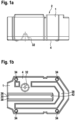
- FIG. 1a A side view of a tank 1 made of plastic for storing oil is shown.
- This has a tank lid 2 or a tank top and a tank bottom 4 or a bottom wall.
- the tank 1 is shown from above.
- the tank 1 also has an outer side wall 6.
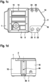
- a flange 8 with a frame-shaped flange surface 10 can be seen from the top. This delimits a cover opening 12 or tank opening. Oil can be introduced into and removed from the tank via the cover opening 12.
- a large number of blind hole recesses 14 are made in the flange surface 10, into which screws can be inserted to fasten a component.
- Functional elements in the form of nuts are integrated within the blind hole recesses 14. These are integrated as inserts during the manufacturing process.
- Fig. 1c It can also be seen that the side wall 6 on the front side of the tank 1 has two outer wall sections 16 and 18 arranged in a V shape relative to one another. These serve to deflect an oil flow, which is explained in more detail below.
- a through-opening 20 for a ventilation filter is formed in the tank cap 2.
- a through-opening 22 is provided, which serves as a filling connection.
- a fill level sensor can be introduced into a tank interior of the tank 1 in a further through-opening 24.
- a through-opening 26 can be used for another function or can be closed with a cap, for example.
- Fig. 1b the bottom wall 4 of the tank 1 is shown. This has a U-shaped recess 28. In addition, a free space 30 is visible. This is designed to be open towards the bottom wall 4 and is delimited by walls which, as explained in more detail below, limit an oil guide in the tank interior. Furthermore, according to Fig. 1b from the bottom wall 4 a diffuser projection 32 inwards. This is concave when viewed from the outside. According to Fig. 1a it can be seen that the diffuser projection 32 is conical and has a wall thickness that corresponds approximately to the wall thickness of the base wall 4. Furthermore, four support elements 34 are integrated into the base wall 4, via which the tank 1 can rest on a base or on a support surface. The support elements 34 are formed in the corner area of the tank 1 and extend downwards away from the base wall 4 in the manner of a projection.
- Fig. 1e The tank 1 is shown in a rear view.
- the free space 30 can be seen. This is open towards the rear.
- the free space 30 is delimited by a first and second inner side wall section 36 and 38. It is delimited at the top by an inner cover section 40.
- the free space 30 has Fig. 1D an inner transverse side wall portion 42 which is provided between the side wall portions 36 and 38.
- the upper inner cover section 40 is arranged below the tank cap 2.
- a front view of the tank 1 is shown.
- the outer wall sections 16 and 18 arranged at an angle to one another can be seen. These approach one another from a respective tank side of the tank 1.
- An optical oil level indicator 44 is formed on the front side. This extends upwards from the bottom wall 4 and ends in the tank lid 2.
- a through hole 46 is formed on the front side as an oil drain.
- a first and second oil connection 48, 50 is provided.
- a cooler can be connected to these. Oil is taken from the oil connection 50 and returned via the oil connection 48.
- FIG. 2 A large-volume return line 52 and a suction line 54 are shown schematically. These are led into the tank interior via the cover opening 12.
- the inner tank space of the tank 1 has a first space leg 56 and a second space leg 58, which are connected via the sections 36, 38, 40 and 42, see. Fig. 1b and e , separated from each other.
- the return line 52 is immersed in the first chamber leg 56 and the intake line 54 is immersed in the second chamber leg 58. Oil is fed into the first chamber leg 56 via the return line 52 and The intake line 54 is used to extract oil via the second chamber leg 58.
- the lines 52 and 54 are connected to a Fig. 2 hydraulic block (not shown).
- Fig. 2 hydraulic block not shown.
- a return line 60 is shown, which has a smaller diameter than the return line 52.
- the return line 60 also opens into the first chamber leg 56 and is connected to the hydraulic block.
- a filter 62 for oil is provided, which is attached to the tank 1. This is inserted into the through hole 20 of Fig. 1c
- a level sensor 64 is shown, which is inserted into the through hole 24 of Fig. 1c is inserted.
- the oil level indicator 44 attached to the front of the tank is also shown. This is connected to the tank interior to indicate the oil level.
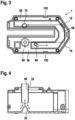
- Fig. 3 shows a cross-section of the tank 1 with the space legs 56 and 58. These are connected to one another via a transverse space leg 66.
- the legs 56, 58 and 66 are arranged in a U-shape, with the legs 56, 58 and 66 being arranged horizontally.
- Oil enters the first space leg 56 via a return opening 68 of the return line 52, shown schematically as a ring, and the return line 60.
- the oil then flows along the first leg 56 and is deflected by 90° by the slanted outer wall sections 16 and 18, which are also slanted on the inside.
- the outer wall sections 16 and 18 delimit the transverse space leg 66.
- the oil then reaches the second space leg 58 via this and can be drawn in via a suction opening 70, which is shown schematically as a ring in Fig. 3
- the suction opening 70 is part of the suction line 54 from Fig. 2 .
- Fig. 4 it can be seen that the return opening 68 of the return line 52 is arranged above the diffuser projection 32. This is arranged approximately coaxially to the conical diffuser projection 32 and slightly spaced from it. Oil that exits from the return opening 68 is evenly split by the diffuser projection 32.
- FIG. 5a A tank 72 according to a second embodiment is shown.
- the top of the tank 72 according to Fig. 5c shows a flange surface 74 which is formed circumferentially around the tank 72.
- a hydraulic block can be or a cover with another flange is arranged or a support frame is attached to it.
- the tank 72 also has a conical diffuser projection 76.
- Fig. 5c It can be seen that the inner tank space is continuously divided by a sheet metal wall 78. In the sheet metal wall 78, according to Fig. 5a a through opening 80 is introduced at the end.
- the tank space Due to the sheet metal wall 78 and the through opening 80, the tank space also has a first and second space leg 82 and 84, which are connected via a transverse space leg 86, see. Fig. 5a , connected in a U-shape. According to Fig. 5b and 5c Sloping front-side outer wall sections 88 and 90 are shown.
- Fig. 6 shows the tank 1 according to the first embodiment together with a hydraulic block 92 and a support frame 94.
- the support frame 94 is provided with a frame-shaped flange section 95 on the flange surface 10 of the flange 8 of the tank 1, see. Fig. 1c , attached.
- the flange section 96 is expanded radially inwards, with the hydraulic block 92 being attached to the extension.
- the hydraulic block 92 is attached to an upper side of the support frame 94 and the tank 1 is attached to an underside of the support frame 94.
- the hydraulic block 92 is supported by the support frame 94 and four support legs 96, two of which are in Fig. 6 can be seen, on the ground.
- the tank 1 is therefore not burdened by the weight of the hydraulic block 92.
- the support structure 94 extends laterally over the tank 1 with its support legs 96.
- Fig. 6 it is a hydraulic unit. This is used, for example, for a hydraulic press brake. It is conceivable that the press has two or more of the arrangements.
- the tank 1 preferably has integrated functional elements. These can be fastening options that are integrated in the tank design. For example, inserted nuts can be provided for fastening the tank to the base or additional components. Other functional elements do not have to be attached separately, for example, but can already be integrated in the tank design and produced by rotational forming.
- crossbeams such as the recess 28 made of Fig. 1b and lateral depressions 100 and 102, see Fig. 3 , which can extend in an up and down direction and can be molded into the tank 1 from the outside, serve to increase the mechanical stability of the tank 1.
Landscapes
- Engineering & Computer Science (AREA)
- Mechanical Engineering (AREA)
- General Engineering & Computer Science (AREA)
- Physics & Mathematics (AREA)
- Fluid Mechanics (AREA)
- Chemical & Material Sciences (AREA)
- Analytical Chemistry (AREA)
- Supply Devices, Intensifiers, Converters, And Telemotors (AREA)
Description
- Die Erfindung betrifft einen Tank für eine Kühlflüssigkeit oder für ein Druckmittel, insbesondere für ein Öl, gemäß dem Oberbegriff des Anspruchs 1. Außerdem betrifft die Erfindung eine Anordnung mit einem Tank und mit einem Hydraulikblock.
- Aus der
DE 10 2018 217 930 A1 ist ein Tank für ein hydraulisches Aggregat offenbart. Dieser dient zum Speichern einer Hydraulikflüssigkeit. Der Tank hat einen oberen Zulaufanschluss und einen darunter angeordneten Ablaufanschluss. Zwischen den Anschlüssen sind Führungswandungen ausgebildet, die eine Strömung der Hydraulikflüssigkeit vom Zulaufanschluss zum Ablaufanschluss führen. Die Strömungsführung ist dabei derart ausgebildet, dass sie zumindest zwei 180° Strömungsbögen zur Kühlung und zur Beruhigung der Hydraulikflüssigkeit und zur Vermeidung von Totzonen aufweist. - Weiterer Stand der Technik kann der
US 2012/055569 A1 , derEP 0 271 702 A2 , derJP 2012 225061 A DE 10 2013 222908 A1 und derJP S49 101186 U - Demgegenüber liegt der Erfindung die Aufgabe zugrunde, einen Tank und Anordnung mit einem Tank zu schaffen, bei dem/der ein vergleichsweises geringes Tankvolumen, eine verbesserte Entgasung und ein verbessertes Klimamanagement vorliegt.
- Die Aufgabe hinsichtlich des Tanks wird gelöst gemäß den Merkmalen des Anspruchs 1 und hinsichtlich der Anordnung gemäß dem Merkmal des Anspruchs 10.
- Vorteilhafte Weiterbildungen der Erfindung sind Gegenstand der Unteransprüche.
- Erfindungsgemäß ist ein Tank für ein Öl vorgesehen. Der Tank hat einen Tankraum zum Speichern des Öls. Der Tankraum weist eine Rücklauföffnung und eine Ansaugöffnung für das Öl die auf. Erfindungsgemäß ist der Tankraum U-förmig mit einem ersten Raumschenkel und einem zweiten Raumschenkel ausgebildet. Die Raumschenkel sind über einen Querraumschenkel des Tankraums verbunden. Mit anderen Worten hat der Tankraum zwei sich parallel zueinander oder angewinkelt zueinander erstreckende Raumschenkel, deren Endseiten über einen Querraumschenkel verbunden sind. Die Rücklauföffnung ist mit dem ersten Raumschenkel und die Ansaugöffnung mit dem zweiten Raumschenkel verbunden. Somit kann Flüssigkeit über die Rücklauföffnung in den Tankraum einströmen und über den ersten Raumschenkel zum zweiten Raumschenkel fließen. Über diesen kann die Flüssigkeit über die Ansaugöffnung wieder aus dem Tankraum austreten. Erfindungsgemäß sind die Schenkel liegend angeordnet. Der Querraumschenkel ist von zwei Außenwandungsabschnitten einer äußeren Seitenwandung begrenzt. Ein Außenwandungsabschnitt ist dann benachbart zum ersten Raumschenkel und der weitere Außenwandungsabschnitt benachbart zum zweiten Raumschenkel angeordnet. Zumindest einer der Außenwandungsabschnitte erstreckt sich im Querschnitt gesehen insbesondere quer zur Oben-Unten-Richtung gesehen, schräg bezüglich einer Längsachse des benachbarten Raumschenkels. Dieser Außenwandungsabschnitt erstreckt sich dabei derart schräg, dass der Tank eine abgeschrägte Ecke zur Strömungsumlenkung des Öls vom ersten Raumschenkel in den zweiten Raumschenkel zu aufweist. Ist ein Freiraum vorgesehen, so reicht zumindest der eine schräg angeordnete Außenwandungsabschnitt hin zum Freiraum. Falls eine Trennwand, beispielsweise in einem Blechtank, vorgesehen ist, so weist der schräg ausgebildete Außenwandungsabschnitt hin zur Trennwand. Vorzugsweise sind beide Außenwandungsabschnitte schräg angeordnet. Die beiden Außenwandungsabschnitte sind dabei beispielsweise V-förmig oder etwa V-förmig zueinander angeordnet. Insbesondere sind die Außenwandungsabschnitte stirnseitig des Tanks vorgesehen, wobei sich der Tank von außen gesehen dann im Bereich des Querraumschenkels verjüngen kann. Durch die schräg angeordneten Außenwandungsabschnitte können Wellen und Turbulenzen in der Flüssigkeit vermieden werden. Mit anderen Worten dienen abgeschrägte Seitenwände zur Vermeidung von Wellen und Turbulenzen. Vorzugsweise sind die Außenwandungsabschnitte derart angeordnet, dass sie die Strömung jeweils um 90° oder um etwa 90° umlenken. Hierdurch wird ein Staudruck vermindert oder weitestgehend vermieden, was eben zur Reduktion der Wellenbewegung und Turbulenz führt. Mit anderen Worten weist der Tank abgeschrägte Ecken zur Strömungsumlenkung von einem Raumschenkel zum anderen Raumschenkel auf. Es hat sich gezeigt, dass durch die liegende Anordnung der Schenkel ein Tankvolumen reduzierbar ist, bei gleichzeitig verbesserter Entgasung und verbessertem Klimamanagement. Durch die U-förmige Strömungsführung ist eine verbesserte Ölausnutzung ermöglicht. Stehende Bereiche oder Totvolumen im Tankraum sind minimiert, weswegen eine Kanalbildung bei warmem Öl vom Rücklauf zur Saugleitung verhindert oder zumindest vermindert ist, da das Öl alle Bereiche im Tankraum durchströmen muss. Durch die zweischenklige Ausgestaltung mit den zwei Raumschenkeln kann zumindest der zweite Raumschenkel als Fluidzone dienen und das Öl auf einfache Weise beruhigen, da dieser vom turbulenten Rücklaufbereich getrennt ist. Es hat sich gezeigt, dass durch die liegende Ausformung der U-förmigen Schenkel eine Entgasung des Öls aufgrund der aktiven Umlenkung der Ölströmung im Vergleich zum Stand der Technik verbessert ist. Außerdem ist ein Klimamanagement im Tank verbessert, da sich gezeigt hat, dass durch die beschriebene Ausgestaltung das Öl im Betrieb nahezu komplett umgewälzt wird. Somit erfolgt eine gute Verteilung des Öls im Tank und die Temperatur des Öls kann genauer erfasst werden, da Temperaturunterschiede im Öl vergleichsweise gering sind.
- Mit anderen Worten erstrecken sich die Schenkel etwa parallel zur Erdoberfläche. Somit ist vorzugsweise kein Gefälle vom Zu- zum Ablauf. Das heißt, die Schenkel können sich quer zur Schwerkraftrichtung erstrecken. Selbstverständlich sind Abweichungen möglich, beispielsweise wenn der Tank in der Mobilhydraulik bei einem Fahrzeug eingesetzt wird, wobei dann die Anordnung des Tanks im Raum von einer Position des Fahrzeugs abhängt. Beispielsweise können sich bei der Anordnung in einem Fahrzeug die Schenkel etwa parallel zu einer Fahrgestellebene erstrecken.
- In weiterer Ausgestaltung der Erfindung kann vorgesehen sein, dass der Tank vorrichtungstechnisch einfach aus Kunststoff gebildet ist. Als äußerst kostengünstige Methode zum Herstellen des Tanks hat sich Rotationsformen erwiesen. Die U-förmige Ausgestaltung des Tanks ist hierfür vorteilhaft geeignet. Bei Bedarf ist denkbar, den Tank durch ein Kunststoffspritzgussverfahren herzustellen.
- Alternativ kann vorgesehen sein, den Tank als Blechtank auszubilden. Wandungen können dann beispielsweise stoffschlüssig, beispielsweise durch Schweißen, verbunden werden oder, zumindest teilweise, durch Biegungen ausgestaltet sein. Der erste Raumschenkel ist vorzugsweise von einem Schenkelboden begrenzt. Am Schenkelboden kann ein Diffusorvorsprung ausgebildet und/oder integriert sein, der sich in den Raumschenkel erstreckt. Durch den Diffusorvorsprung kann vorteilhaft die Flüssigkeitsströmung im Tankraum aufgespalten werden, so dass insbesondere kein sogenanntes Schwappen entsteht. Vorzugsweise ist der Diffusorvorsprung hierfür gegenüber der, insbesondere oben angeordneten, Rücklauföffnung ausgebildet. Alternativ oder zusätzlich ist denkbar, einen weiteren Diffusorvorsprung am zweiten Raumschenkel am Schenkelboden auszubilden, insbesondere gegenüber zur Nachsaugleitung, um eine Strömung verbessert zu führen. Die Anleitung des Diffusorvorsprungs gegenüber der Rücklauföffnung oder Rücklaufleitung hat den Vorteil, dass hier der größte Volumenstrom vorherrschen kann, wenn Flüssigkeit in den Tankraum strömt. Der Diffusorvorsprung kann mit anderen Worten in axialer geometrischer Verlängerung der Rücklauföffnung oder der Rücklaufleitung vorgesehen sein. Die Rücklauföffnung ist vorzugsweise oberhalb des Tankraums angeordnet. Die Rücklauföffnung kann beispielsweise derart gestaltet sein, dass Flüssigkeit etwa in Schwerkraftrichtung in den Tankraum strömt. Der Diffusorvorsprung verjüngt sich vorzugsweise nach innen in Richtung weg vom Schenkelboden. Er kann beispielsweise kegelförmig oder kegelstrumpfförmig oder pyramidenförmig oder rotationssymmetrisch ausgestaltet sein. Von außen gesehen ist denkbar, dass der Diffusorvorsprung konkav ausgestaltet ist. Er kann integraler Bestandteil des Schenkelbodens sein und beispielsweise durch das Rotationsformen zusammen mit dem Tank einfach hergestellt werden. Eine Wandungsdicke des Diffusorvorsprungs entspricht beispielsweise einer Wandungsdicke des Schenkelbodens. Mit anderen Worten ist in die Tankwand oder in den Tankboden eine Kegelgeometrie integriert, die die Ölströmung idealer im Tank aufspaltet. Eine Längsachse des Diffusorvorsprungs ist vorzugsweise koaxial oder etwa koaxial zu einer Längsachse der Rücklauföffnung. "Etwa" kann heißen, dass Toleranzen zugelassen werden, so dass die generelle Funktion des Diffusorvorsprungs ermöglicht ist. In weiterer Ausgestaltung, insbesondere alternativ oder zusätzlich, kann vorgesehen sein, dass eine Strömungsrichtung der aus der Rücklauföffnung austretenden Flüssigkeit auf den Diffusorvorsprung zeigt. Die Strömungsrichtung und eine Längsachse des Diffusorvorsprungs sind beispielsweise zumindest etwa im Parallelabstand zueinander angeordnet. Wie bereits angeführt, kann die Rücklauföffnung oberhalb vom Diffusorvorsprung angeordnet sein.
- In weiterer Ausgestaltung der Erfindung sind die Schenkel vorzugsweise von einer Seitenwandung des Tanks begrenzt. Insbesondere kann der Tank als U-förmige Wanne ausgebildet sein. Denkbar wäre auch, den Tank als Wanne auszugestalten, der von einer inneren Wandung zweigeteilt ist, wobei die innere Wandung eine Durchgangsöffnung aufweist, um die durch die innere Wandung voneinander getrennten Raumschenkel miteinander zu verbinden, um somit eine etwa U-förmige Ausgestaltung zu erreichen.
- Vorzugsweise ist zwischen dem ersten und zweiten Raumschenkel ein Tankfreiraum gebildet. Dieser kann von einem ersten und von einem zweiten Seitenwandungsabschnitt begrenzt sein. Diese Seitenwandlungsabschnitte wiederum können jeweils den ersten und zweiten Raumschenkel begrenzen. Zwischen den beiden Seitenwandungsabschnitten kann dann den Querraumschenkel begrenzender Querseitenwandungsabschnitt vorgesehen sein. Die Seitenwandungsabschnitte und der Querseitenwandungsabschnitt können sich von einem Tankboden aus oder von Schenkelböden oder den Schenkelböden aus nach oben erstrecken. Vorzugsweise sind die Seitenwandungsabschnitte und der Querseitenwandungsabschnitt U-förmig ausgebildet und bilden somit eine U-förmige Innenwandung für die Schenkel.
- In weiterer Ausgestaltung der Erfindung kann der Tankfreiraum, der von den Seitenwandungsabschnitten und dem Querseitenwandungsabschnitt begrenzt ist, oben, insbesondere in Schwerkraftrichtung gesehen, von einem Innendeckelabschnitt des Tanks verschlossen sein. Es ist denkbar, dass der Tankfreiraum nach unten hin, insbesondere in Schwerkraftrichtung gesehen, und/oder in Richtung weg von dem Querraumschenkel offen ist. Somit kann der Tankfreiraum nach innen hin geschlossen sein und nach außen hin geöffnet sein, wodurch dieser einfach herstellbar ist. Eine Höhe des Tankfreiraums ist vorzugsweise geringer als die Tankhöhe des Tanks. Hierdurch ist ermöglicht, dass der Innendeckelabschnitt bei Bedarf überspülbar ist. Bei Bedarf kann somit Flüssigkeit vom einen Raumschenkel über den Innendeckelabschnitt zum anderen Raumschenkel fließen.
- Es ist denkbar, dass sich die Seitenwandungsabschnitte und bei Bedarf auch der Querseitenwandungsabschnitt in Richtung von unten nach oben annähern, womit auf einfache Weise das innere Tankvolumen des Tanks vergrößerbar ist und eine einfache Herstellung des Freiraums ermöglicht ist.
- Vorzugsweise hat der Tank einen Tankdeckel, der die Schenkelräume überdeckt. Dieser ist vorzugsweiser einstückig mit dem Tank ausgebildet und beispielsweise beim Rotationsformen hergestellt. Ist ein Freiraum mit einem Innendeckelabschnitt vorgesehen, so kann dieser zum Tankdeckel beabstandet sein. Denkbar ist auch, dass der Innendeckelabschnitt ein Teil des Tankdeckels ist.
- Vorzugsweise sind die Schenkel von einer äußeren Seitenwandung begrenzt, die insbesondere einstückig mit dem Tankdeckel verbunden ist und weiter vorzugsweise einstückig mit einem Tankboden oder den Schenkelböden oder Schenkelböden verbunden ist. Die äußere Seitenwandung umgreift vorzugsweise die inneren Seitenwandungsabschnitte mit dem Querseitenwandungsabschnitt derart, dass die U-förmigen Schenkel ausgebildet sind.
- In weiterer Ausgestaltung der Erfindung sind die Schenkel von einer Bodenwandung von unten begrenzt. Diese kann beispielsweise einfach U-förmig ausgestaltet sein. Die äußere Seitenwandung ist dann vorzugsweise einstückig zwischen den Tankdeckel und der Bodenwandung ausgebildet. Die Schenkelböden können ein Teil der Bodenwandung sein.
- Mit Vorteil ist in die Bodenwandung des Tanks eine U-förmige Vertiefung eingebracht, die sich entlang der Schenkel erstreckt. Die Vertiefung kann von außen gesehen konkav und von innen gesehen konvex ausgebildet sein. Denkbar wäre, dass die Vertiefungen eine oder mehrere Unterbrechungen aufweist. Die Vertiefung unterstützt zum einen die Strömungsführung und zum anderen kann sie vorteilhaft zu einer Versteifung des Tanks, insbesondere der Bodenwandung führen. Die U-förmige Vertiefung erstreckt sich vorzugsweise etwa im Parallelabstand zu den Schenkeln. Eine Breite der Vertiefung kann kleiner als eine bodenseitige Breite der Schenkel sein. Die Vertiefung ist vorzugsweise von den Wandungen beabstandet.
- In weiterer Ausgestaltung der Erfindung kann die äußere Seitenwandung bei einem oder bei beiden Raumschenkeln zumindest oder jeweils zumindest eine innere Querrippe aufweisen. Diese kann sich etwa oder genau in Richtung von oben nach unten erstrecken. Die Querrippe führt insbesondere zu einer vorteilhaften Versteifung des Tanks.
- Mit anderen Worten kann durch traverse Stege die mechanische Stabilität des Tanks verbessert werden.
- Vorzugsweise hat der Tankdeckel des Tanks einen Flansch. Dieser kann derart ausgestaltet sein, dass dieser direkt oder über ein weiteres Bauteil mit einem Hydraulikblock verbindbar ist. Vorzugsweise hat der Flansch eine ringförmige Flanschfläche. Die Flanschfläche kann sich beispielsweise in einer Ebene erstrecken, insbesondere in einer Ebene quer zur Schwerkraft- oder Oben-Unten-Richtung. Die Flanschfläche umfasst vorzugsweise eine Deckelöffnung des Tankdeckels. Über die Deckelöffnung können einfach Leitungen für den Rücklauf und die Ansaugung in den Tank eingeführt werden. Über die Deckelöffnung sind vorzugsweise beide Raumschenkel zugänglich. Es ist denkbar, dass die beiden Raumschenkel über die Deckelöffnung nach oben hin offen sind, wobei die Deckelöffnung beispielsweise von einem Hydraulikblock abgedeckt sein kann. Die Deckelöffnung kann dann derart ausgestaltet sein, dass Leitungen des Hydraulikblocks über die Deckelöffnung in die Raumschenkel, insbesondere genau oder etwa in Schwerkraft- oder Oben-Unten-Richtung kragen.
- Vorzugsweise hat der Tank ein Traggestell, über das der Tank festlegbar ist. Das Traggestell kann beispielsweise U-förmig ausgebildet sein. Alternativ oder zusätzlich kann das Traggestell derart ausgestaltet sein, dass sich dieses an einer Bodenfläche oder einer Bauteilkomponente abstützt. Vorzugsweise ist eine Oberseite des Tanks mit dem Traggestell fest verbunden. Zumindest ist denkbar, dass ein Teil des Tankgewichts oder das gesamten Tankgewicht über die Oberseite vom Traggestell getragen wird. Das Traggestell kann den Tank übergreifen und sich an der Bodenfläche abstützen. Ist das Traggestell beispielsweise U-förmig ausgestaltet, so ist denkbar, dass der Tank zwischen den Gestellschenkeln angeordnet ist. In weiterer Ausgestaltung der Erfindung kann vorgesehen sein, dass das Traggestell über die Flanschfläche des Tanks, insbesondere über einen auf der Flanschfläche angeordneten Dichtring, mit dem Tank über Mittel befestigt ist. Als Mittel dienen beispielsweise Schraubverbindungen. Das Traggestell kann auch einen Flanschabschnitt aufweisen, der auf der Flanschfläche des Tanks befestigt ist und die Deckelöffnung umfasst. Vorzugsweise bildet der Flanschabschnitt die Verbindung zwischen den Gestellschenkeln. Des Weiteren ist denkbar, dass das Traggestell Stützbeine hat, über die das Traggestell an der Bodenfläche abstützbar ist und die mit dem Flanschabschnitt verbunden sind. Der Tank kann beispielsweise derart ausgestaltet sein, dass dieser sich zum einen an der Bodenfläche direkt und zusätzlich über das Traggestell abstützt. Somit ist eine sichere Befestigung des Tanks ermöglicht. Weiter vorzugsweise ist der Hydraulikblock am Traggestell befestigt. Vorzugsweise hat das Traggestell innerhalb des Flanschabschnitts Befestigungsabschnitte oder einen Befestigungsabschnitt für den Hydraulikblock. Der Tank ist somit nicht direkt mit dem Hydraulikblock verbunden, sondern über das Traggestell. Das Gewicht des Hydraulikblocks wird somit vorzugsweise über das Traggestell abgestützt und nicht über den Tank. Dieser kann somit einfacher ausgestaltet werden.
- In weiterer Ausgestaltung der Erfindung weist der Tank einen Kühlerablaufanschluss und einen Kühlerzulaufanschluss auf. Der Kühlerablaufanschluss ist vorzugsweise mit dem einen Raumschenkel und der Kühlerzulaufanschluss vorzugsweise mit dem anderen Raumschenkel verbunden. Somit kann Flüssigkeit von dem Tankraum entnommen werden und nach Durchlaufen des Kühlers in den Tankraum zurückgeführt werden. Vorzugsweise ist der Kühlerablaufanschluss mit dem ersten Raumschenkel und der Kühlerzulaufanschluss mit dem zweiten Raumschenkel verbunden. Über den Kühler kann somit Flüssigkeit vom Rücklaufanschluss zum Nachsauganschluss geführt werden, womit die Strömungsführung im Tank entlastet wird. Die Kühleranschlüsse sind vorzugsweise stirnseitig der Raumschenkel vorgesehen, insbesondere auf Seiten weg von dem Querraumschenkel. Die Anschlüsse sind dabei vorzugsweise in der äußeren Seitenwandung eingebracht. An dem Kühlerablaufanschluss und an dem Kühlerzulaufanschluss kann eine aktive Flüssigkeit- oder Ölkühlung angeschlossen sein. Diese kann das Öl beispielsweise zwischen zwei Kammern umwälzen. Hierdurch kann eine Kühlung des Tanks verbessert werden und ein Kurzschluss von dem Rücklaufanschluss zum Sauganschluss kann unterbunden werden. Durch die aktive Kühlung kann eine Reduzierung temperaturbedingter Ölalterung erfolgen.
- In weiterer Ausgestaltung der Erfindung hat der Tank einen oder mehrere Anschlüsse, insbesondere für: Den Kühlerablaufanschluss und/oder den Kühlerzulaufanschluss und/oder einen Anschluss für eine Füllstandanzeige und/oder einen Anschluss für einen Belüftungsfilter und/oder einen Befüllanschluss und/oder einen Ölablass und/oder einen Anschluss für einen Füllstandsensor und/oder zumindest einen Anschluss als Reserve für eine Funktion und/oder einen Anschluss für einen optischen Ölstandanzeiger. Die Anschlüsse sind dabei vorzugsweise in den Tank integriert. Weiter vorzugsweise weist der Tank in die Bodenwandung integrierter Befestigungsvorrichtungen auf, um den Tank am Boden zu befestigen.
- Beispielsweise sind Befestigungselemente in den Tank integriert, wie eingelegte Muttern, zur Befestigung des Tanks an einem Untergrund, oder zum Befestigen zusätzlicher Bauteile. Mit anderen Worten weist der Tank ein oder mehrere integrierte/s Funktionselement/e auf, wie beispielsweise Befestigungselemente zum Befestigen des Tanks und/oder zum Befestigen einer oder mehrerer Komponente/n.
- Neben der Rücklaufleitung kann in dem Tank eine weitere großvolumige Rücklaufleitung, insbesondere über die Tanköffnung, münden. Die Leitungen, also die Rücklaufleitungen und die Ansaugleitungen erstrecken sich vorzugsweise ausgehend vom Hydraulikblock frei in den Tankraum.
- Die Tanköffnung und/oder Rücklauföffnung und/oder Tanköffnung umfasst zumindest einen Teil der Leitungen oder alle Leitungen, aber dichtet diese nicht ab, d. h. es sind keine Dichtmittel zwischen den Leitungen und der Öffnung notwendig. Der Anschluss der Leitungen erfolgt über den Hydraulikblock. Vorzugsweise handelt es sich bei der Rücklauföffnung und/oder der Ansaugöffnung und/oder der Tanköffnung somit um keinen Anschluss, weswegen der Tank vereinfacht ausgestaltbar ist.
- Erfindungsgemäß ist eine Anordnung mit dem Tank gemäß einem oder mehreren der vorhergehenden Aspekte und mit einem Hydraulikblock vorgesehen. Der Tank eignet sich besonders vorteilhaft für die Kombination mit dem Hydraulikblock.
- Der erfindungsgemäße Tank weist ein vergleichsweise geringes Ölvolumen, insbesondere durch verbesserte Strömungsführung, auf. Die verbesserte Strömungsführung erfolgt insbesondere durch die Trennung von Rücklauf, Saugleitung und Nachsaugung und/oder durch die abgeschrägten Seitenwände. Bei dem erfindungsgemäßen Tank ist außerdem die Entgasung verbessert und es kann die temperaturbedingte Ölalterung reduziert werden, insbesondere durch Anschluss eines Kühlers. Es ist außerdem ein verbessertes Temperaturmanagement ermöglicht. Der Tank mit der Vielzahl von Funktionen kann beispielsweise mittels Kunststoff-Rotationsformen hergestellt werden. Vorzugsweise sind die Rücklauföffnung und die Ansaugöffnung Teil des Hydraulikblocks, wobei diese an Leitungen ausgebildet sein können. Die Leitungen können dann in den Tankraum ragen. Die Leitungen können vorzugsweise mit dem Hydraulikblock fest verbunden sein, insbesondere verschraubt sein. Somit benötigt der Tank keine Befestigungsmöglichkeit für die Leitungen, wodurch dieser weiter vorrichtungstechnisch einfach ausgestaltet werden kann. Mit anderen Worten sind tankseitige Anschlüsse im Hydraulikblock geschraubt und ragen in die Innenseite des Hydrauliktanks.Offenbart ist ein Tank mit Seitenwänden, einem Boden und einer Decke. Der Tank kann als U-förmige Wanne ausgeführt sein, wodurch der Strömungsweg von einer Saug- und einer Nachsaugleitung beim kleinen Bauraum maximiert ist.
- Bevorzugte Ausführungsbeispiele der Erfindung werden im Folgenden anhand schematischer Zeichnungen näher erläutert. Es zeigen:
-
Figuren 1a bis 1e verschiedene Ansichten eines Tanks gemäß einem ersten Ausführungsbeispiel, -
Figur 2 in einer perspektivischen Darstellung den Tank gemäß dem ersten Ausführungsbeispiel, -
Figur 3 in einer Draufsicht einen Querschnitt des Tanks gemäß dem ersten Ausführungsbeispiel, -
Figur 4 in einer Seitenansicht einen Längsschnitt des Tanks gemäß dem ersten Ausführungsbeispiel, -
Figuren 5a bis 5c verschiedene Ansichten eines Tanks gemäß einem weiteren Ausführungsbeispiel, -
Fig. 6 in einer perspektivischen Darstellung eine Anordnung mit dem Tank gemäß dem ersten Ausführungsbeispiel und mit einem Hydraulikblock. - Gemäß
Fig. 1a ist in einer Seitenansicht ein Tank 1 aus Kunststoff zum Speichern von Öl dargestellt. Dieser hat einen Tankdeckel 2 oder eine Tankoberseite und einen Tankboden 4 oder eine Bodenwandung. GemäßFig. 1c ist der Tank 1 von oben dargestellt. Der Tank 1 hat weiter eine äußere Seitenwandung 6. Von der Oberseite ist ein Flansch 8 mit einer rahmenförmigen Flanschfläche 10 ersichtlich. Diese begrenzt eine Deckelöffnung 12 oder Tanköffnung. Über die Deckelöffnung 12 kann Öl in den Tank eingeführt und von diesem entnommen werden. In die Flanschfläche 10 sind eine Vielzahl von Sacklochaussparungen 14 eingebracht, in die Schrauben zum Befestigen einer Komponente einführbar sind. Innerhalb der Sacklochaussparungen 14 sind Funktionselemente in Form von Muttern integriert. Diese werden beim Herstellungsverfahren als Einlegeteile integriert. - Gemäß
Fig. 1c ist weiter erkennbar, dass die Seitenwandung 6 stirnseitig des Tanks 1 zwei V-förmig zueinander angeordnete Außenwandungsabschnitte 16 und 18 aufweist. Diese dienen zur Umlenkung einer Ölströmung, was unterstehend näher erläutert ist. - Gemäß
Fig. 1c ist in den Tankdeckel 2 eine Durchgangsöffnung 20 für einen Belüftungsfilter ausgebildet. Außerdem ist eine Durchgangsöffnung 22 vorgesehen, die als Befüllanschluss dient. In einer weiteren Durchgangsöffnung 24 kann ein Füllstandsensor in ein Tankinneres des Tanks 1 eingeführt werden. Eine Durchgangsöffnung 26 kann für eine weitere Funktion eingesetzt werden oder beispielsweise mit einer Kappe verschlossen werden. - Gemäß
Fig. 1b ist die Bodenwandung 4 des Tanks 1 dargestellt. Diese weist eine U-förmige Vertiefung 28 auf. Außerdem ist ein Freiraum 30 ersichtlich. Dieser ist nach unten hin zur Bodenwandung 4 offen ausgestaltet und von Wandungen begrenzt, die im Tankinneren, wie untenstehend näher erläutert ist, eine Ölführung begrenzen. Des Weiteren erstreckt sich gemäßFig. 1b von der Bodenwandung 4 ein Diffusorvorsprung 32 nach innen. Dieser ist von außen gesehen konkav ausgestaltet. GemäßFig. 1a ist erkennbar, dass der Diffusorvorsprung 32 kegelförmig ist und eine Wandstärke hat, die etwa der Wandstärke der Bodenwandung 4 entspricht. In die Bodenwandung 4 sind des Weiteren vier Stützelemente 34 integriert, über die der Tank 1 an einem Boden oder an einer Auflagefläche aufliegen kann. Die Stützelemente 34 sind im Eckbereich des Tanks 1 ausgebildet und erstrecken sich vorsprungartig nach unten weg von der Bodenwandung 4. - Gemäß
Fig. 1e ist in einer Rückansicht der Tank 1 dargestellt. Es ist der Freiraum 30 erkennbar. Dieser ist nach hinten hin offen ausgebildet. Der Freiraum 30 ist von einem ersten und zweiten inneren Seitenwandungsabschnitt 36 und 38 begrenzt. Nach oben hin ist er über einen Innendeckelabschnitt 40 begrenzt. Außerdem weist der Freiraum 30 gemäßFig. 1D einen inneren Querseitenwandungsabschnitt 42 auf, der zwischen den Seitenwandungsabschnitten 36 und 38 vorgesehen ist. GemäßFig. 1e ist weiter erkennbar, dass der obere Innendeckelabschnitt 40 unterhalb des Tankdeckels 2 angeordnet ist. - Gemäß
Fig. 1d ist eine Vorderansicht des Tanks 1 dargestellt. Es sind die schräg zueinander angeordneten Außenwandungsabschnitte 16 und 18 erkennbar. Diese nähern sich von einer jeweiligen Tankseite des Tanks 1 aneinander an. Stirnseitig ist ein optischer Ölstandanzeiger 44 ausgebildet. Dieser erstreckt sich ausgehend von der Bodenwandung 4 nach oben und mündet im Tankdeckel 2. Außerdem ist gemäßFig. 1b stirnseitig eine Durchgangsöffnung 46 als Ölablass ausgebildet. - In der Rückansicht gemäß
Fig. 1e ist ein erster und zweiter Ölanschluss 48, 50 vorgesehen. An diese kann ein Kühler angeschlossen werden. Aus dem Ölanschluss 50 wird dabei Öl entnommen und über den Ölanschluss 48 zurückgeführt. - Gemäß
Fig. 2 ist schematisch eine großvolumige Rücklaufleitung 52 und eine Ansaugleitung 54 dargestellt. Diese werden über die Deckelöffnung 12 in das Tankinnere geführt. Der innere Tankraum des Tanks 1 hat einen ersten Raumschenkel 56 und einen zweiten Raumschenkel 58, die über die Abschnitte 36, 38, 40 und 42, s.Fig. 1b unde , voneinander getrennt sind. In den ersten Raumschenkel 56 taucht die Rücklaufleitung 52 und in den zweiten Raumschenkel 58 die Ansaugleitung 54 ein. Über die Rücklaufleitung 52 wird Öl in den ersten Raumschenkel 56 zugeführt und über die Ansaugleitung 54 wird Öl über den zweiten Raumschenkel 58 entnommen. Die Leitungen 52 und 54 sind mit einem in derFig. 2 nicht dargestellten Hydraulikblock verbunden. Außerdem ist gemäßFig. 2 eine Rücklaufleitung 60 dargestellt, die einen kleineren Durchmesser als die Rücklaufleitung 52 aufweist. Die Rücklaufleitung 60 mündet ebenfalls im ersten Raumschenkel 56 und ist mit dem Hydraulikblock verbunden. GemäßFig. 2 ist des Weiteren ein am Tank 1 befestigter Filter 62 für Öl vorgesehen. Dieser ist in die Durchgangsöffnung 20 ausFig. 1c eingesetzt. GemäßFig. 2 ist des Weiteren ein Füllstandsensor 64 gezeigt, der in die Durchgangsöffnung 24 ausFig. 1c eingesetzt ist. Außerdem ist der stirnseitig an Tank befestigte Ölstandanzeiger 44 dargestellt. Dieser ist mit dem Tankinnenraum verbunden, um den Ölstand anzuzeigen. -
Fig. 3 zeigt im Querschnitt den Tank 1 mit den Raumschenkeln 56 und 58. Diese sind über einen Querraumschenkel 66 miteinander verbunden. Die Schenkel 56, 58 und 66 sind U-förmig angeordnet, wobei die Schenkel 56, 58 und 66 liegend angeordnet sind. Über eine schematisch als Ring dargestellte Rücklauföffnung 68 der Rücklaufleitung 52 und die Rücklaufleitung 60 tritt Öl in den ersten Raumschenkel 56 ein. Das Öl strömt dann entlang des ersten Schenkels 56 und wird durch die schrägen Außenwandungsabschnitte 16 und 18, die innenseitig ebenfalls schräg ausgebildet sind, jeweils um 90° umgelenkt. Die Außenwandungsabschnitte 16 und 18 begrenzen dabei den Querraumschenkel 66. Über diesen gelangt dann das Öl zum zweiten Raumschenkel 58 und kann über eine Ansaugöffnung 70, die schematisch als Ring inFig. 3 dargestellt ist, angesaugt werden. Die Ansaugöffnung 70 ist dabei Teil der Ansaugleitung 54 ausFig. 2 . - Gemäß
Fig. 4 ist erkennbar, dass die Rücklauföffnung 68 der Rücklaufleitung 52 überhalb des Diffusorvorsprungs 32 angeordnet ist. Diese ist dabei etwa koaxial zum kegelförmigen Diffusorvorsprung 32 angeordnet und etwas von diesem beabstandet. Öl, das aus der Rücklauföffnung 68 austritt, wird von dem Diffusorvorsprung 32 gleichmäßig aufgespalten. - Gemäß
Fig. 5a ist ein Tank 72 gemäß einem zweiten Ausführungsbeispiel gezeigt. Dieser ist hierbei im Unterschied zurFig. 1 aus Blech ausgebildet. Die Oberseite des Tanks 72 gemäßFig. 5c zeigt eine Flanschfläche 74, die umlaufend um den Tank 72 ausgebildet ist. Über die Flanschfläche 74 kann beispielsweise ein Hydraulikblock befestigt werden oder es wird ein Deckel mit einem weiteren Flansch angeordnet oder daran wird ein Traggestell befestigt. GemäßFig. 5a weist der Tank 72 ebenfalls einen kegelförmigen Diffusorvorsprung 76 auf. GemäßFig. 5c ist erkennbar, dass der innere Tankraum durchgehend von einer Blechwandung 78 geteilt ist. In die Blechwandung 78 ist gemäßFig. 5a endseitig eine Durchgangsöffnung 80 eingebracht. Durch die Blechwandung 78 und die Durchgangsöffnung 80 weist der Tankraum ebenfalls einen ersten und zweiten Raumschenkel 82 und 84 auf, die über einen Querraumschenkel 86, s.Fig. 5a , U-förmig verbunden sind. GemäßFig. 5b und5c sind schräge stirnseitige Außenwandungsabschnitte 88 und 90 dargestellt. -
Fig. 6 zeigt den Tank 1 gemäß dem ersten Ausführungsbeispiel zusammen mit einem Hydraulikblock 92 und einem Traggestell 94. Das Traggestellt 94 ist mit einem rahmenförmigen Flanschabschnitt 95 auf der Flanschfläche 10 des Flansches 8 des Tanks 1, s.Fig. 1c , befestigt. Der Flanschabschnitt 96 ist radial nach innen erweitert, wobei auf der Erweiterung der Hydraulikblock 92 befestigt ist. Der Hydraulikblock 92 ist dabei auf einer Oberseite des Traggestells 94 und der Tank 1 auf einer Unterseite des Traggestells 94 befestigt. Der Hydraulikblock 92 stützt sich dabei über das Traggestell 94 und vier Stützbeine 96, von denen zwei inFig. 6 ersichtlich sind, am Boden ab. Der Tank 1 ist somit nicht vom Gewicht des Hydraulikblocks 92 belastet. Tragstruktur 94 übergreift mit ihren Stützbeinen 96 den Tank 1 seitlich. - Bei der Anordnung gemäß
Fig. 6 handelt es sich beispielsweise um ein hydraulisches Aggregat. Dieses wird beispielsweise für eine hydraulische Abkantpresse eingesetzt. Denkbar ist, dass die Presse zwei oder mehr von den Anordnungen aufweist. - Der Tank 1 weist vorzugsweise integrierte Funktionselemente auf. Hierbei kann es sich um Befestigungsmöglichkeiten handeln, die im Tankdesign integriert sind. Beispielsweise können eingelegte Muttern zur Befestigung des Tanks am Untergrund oder von zusätzlichen Bauteilen vorgesehen sein. Weitere Funktionselemente müssen beispielsweise nicht zusätzlich angebracht werden, sondern können bereits im Tankdesign integriert sein und durch das Rotationsverformen hergestellt sein. Durch Traversen, wie beispielsweise die Vertiefung 28 aus
Fig. 1b und seitliche Vertiefungen 100 und 102, s.Fig. 3 , die sich in einer Oben- und Unten-Richtung erstrecken können und von außen im Tank 1 eingeformt werden können, dienen zur Erhöhung einer mechanischen Stabilität des Tanks 1.
Claims (10)
- Tank für ein Öl, der einen Tankraum zum Speichern des Öls hat, wobei der Tankraum eine Rücklauföffnung (68) und eine Ansaugöffnung (70) für das Öl aufweist, wobei der Tankraum U-Förmig mit einem ersten Raumschenkel (56; 82) und mit einem zweiten Raumschenkel (58; 84), die über einen Querraumschenkel (66; 86) des Tankraums verbunden sind, ausgestaltet ist, wobei die Rücklauföffnung (68) mit dem ersten Raumschenkel (56; 82) und die Ansaugöffnung (70) mit dem zweiten Raumschenkel (58; 84) verbunden ist, und wobei die Schenkel (56; 82, 58; 84, 66; 86) liegend angeordnet sind, wobei der Querraumschenkel (66; 86) von zwei Außenwandungsabschnitten (16, 18; 88, 90) einer äußeren Seitenwandung (6) begrenzt ist, wobei ein Außenwandungsabschnitt (16; 88) benachbart zum ersten Raumschenkel (56; 82) und der weitere Außenwandungsabschnitt (18; 90) benachbart zum zweiten Raumschenkel (58; 84) angeordnet ist, dadurch gekennzeichnet, dass sich zumindest einer der Außenwandungsabschnitte (16, 18; 88, 90) im Querschnitt gesehen derart schräg bezüglich einer Längsachse des benachbarten Raumschenkels (56; 82, 58; 84) erstreckt, dass der Tank eine abgeschrägte Ecke zur Strömungsumlenkung des Öls vom ersten Raumschenkel (56; 82) in den zweiten Raumschenkel zu (58; 84) aufweist.
- Tank nach Anspruch 1, wobei der erste Raumschenkel (56; 82) von einem Schenkelboden (4) begrenzt ist, von dem aus sich ein in den Schenkelboden (4) integrierter Diffusorvorsprung (32; 76) in den ersten Raumschenkel (56; 82) erstreckt.
- Tank nach Anspruch 2, wobei der Diffusorvorsprung (32; 76) gegenüber der Rücklauföffnung (68) ausgebildet ist.
- Tank nach einem der vorhergehenden Ansprüche, wobei zwischen dem ersten Raumschenkel (56; 82) und dem zweiten Raumschenkel (58; 84) ein Tankfreiraum (30) gebildet ist.
- Tank nach einem der vorhergehenden Ansprüche, wobei ein Tankdeckel (2) des Tanks (1) einen Flansch (8) hat, der derart ausgestaltet ist, um einen Hydraulikblock (92) und/oder ein Traggestell (94) zu befestigen.
- Tank nach Anspruch 5, wobei der Flansch (8) eine ringförmige Flanschfläche (10; 74) hat, die eine Deckelöffnung (12) des Tankdeckels (2) umfasst.
- Tank nach einem der vorhergehenden Ansprüche, wobei über die oder eine Deckelöffnung (12) die Raumschenkel (56, 58; 82, 84) für die Zufuhr und Abfuhr des Öls zugänglich sind.
- Tank nach einem der vorhergehenden Ansprüche, wobei ein Traggestell (94) vorgesehen ist, um den Tank (1; 72) zu befestigen, wobei dieses einen Flanschabschnitt (96) hat, der auf der oder einer Flanschfläche (10; 74) des Tanks (1) befestigt ist und die oder eine Deckelöffnung (12) umfasst.
- Tank nach einem der vorhergehenden Ansprüche, wobei ein Kühlerablaufanschluss (50) mit dem einen Raumschenkel (56; 82) und ein Kühlerzulaufanschluss (48) mit dem anderen Raumschenkel (58; 84) verbunden ist.
- Anordnung mit dem Tank gemäß einem der vorhergehenden Ansprüche und mit einem Hydraulikblock (92).
Applications Claiming Priority (1)
| Application Number | Priority Date | Filing Date | Title |
|---|---|---|---|
| DE102021203767.4A DE102021203767A1 (de) | 2021-04-16 | 2021-04-16 | Tank und Anordnung mit einem Tank |
Publications (2)
| Publication Number | Publication Date |
|---|---|
| EP4074966A1 EP4074966A1 (de) | 2022-10-19 |
| EP4074966B1 true EP4074966B1 (de) | 2024-11-27 |
Family
ID=81306827
Family Applications (1)
| Application Number | Title | Priority Date | Filing Date |
|---|---|---|---|
| EP22167628.1A Active EP4074966B1 (de) | 2021-04-16 | 2022-04-11 | Tank und anordnung mit einem tank |
Country Status (2)
| Country | Link |
|---|---|
| EP (1) | EP4074966B1 (de) |
| DE (1) | DE102021203767A1 (de) |
Family Cites Families (7)
| Publication number | Priority date | Publication date | Assignee | Title |
|---|---|---|---|---|
| JPS5236953Y2 (de) * | 1972-12-22 | 1977-08-23 | ||
| DE3643265A1 (de) | 1986-12-18 | 1988-07-07 | Man Nutzfahrzeuge Gmbh | Oelbehaelter zur oelversorgung von hydraulischen arbeitskreisen mit speicherfunktion und zur wiederaufnahme rueckgeleiteten oeles |
| US9109612B2 (en) * | 2009-06-01 | 2015-08-18 | Caterpillar Global Mining Llc | Sealed hydraulic tank system for mining shovel |
| JP2012225061A (ja) | 2011-04-20 | 2012-11-15 | Hitachi Constr Mach Co Ltd | 油圧式作業機械の作動油タンク |
| DE102013222908A1 (de) * | 2013-11-11 | 2015-05-13 | Mahle International Gmbh | Hydrauliktank |
| DE102018217903A1 (de) | 2018-10-18 | 2020-04-23 | Leica Microsystems Cms Gmbh | Inferenz Mikroskopie |
| DE102018217930A1 (de) | 2018-10-19 | 2020-04-23 | Robert Bosch Gmbh | Tank für ein hydraulisches Aggregat |
-
2021
- 2021-04-16 DE DE102021203767.4A patent/DE102021203767A1/de active Pending
-
2022
- 2022-04-11 EP EP22167628.1A patent/EP4074966B1/de active Active
Also Published As
| Publication number | Publication date |
|---|---|
| DE102021203767A1 (de) | 2022-10-20 |
| EP4074966A1 (de) | 2022-10-19 |
Similar Documents
| Publication | Publication Date | Title |
|---|---|---|
| EP1163122B1 (de) | Kraftstofftank für ein kraftfahrzeug | |
| DE69209303T2 (de) | Expansionstank für ein kühlsystem einer brennkraftmaschine | |
| DE102009055157A1 (de) | Verfahren zum Herstellen eines Grundkörpers einer Ölwanne und durch ein solches Verfahren hergestellter Grundkörper einer Ölwanne | |
| DE3546462A1 (de) | Anordnung zur gasabscheidung | |
| EP2046474A1 (de) | Filtersystem für fluide | |
| EP0213414B1 (de) | Betriebsmittelbehälter in Kraftfahrzeugen | |
| EP1878891B1 (de) | Vertikal geteilter Ausgleichbehälter für Kühlflüssigkeit | |
| DE3204493C2 (de) | Baueinheit mit einem Wasserkasten und einem Ausdehnungsgefäß für einen Wärmeaustauscher | |
| DE102018203948B3 (de) | Füllstandsausgleichsbehälter für einen Fluidkreislauf eines Kraftfahrzeugs, Verfahren zum Betreiben eines Füllstandsausgleichsbehälters sowie Kraftfahrzeug mit einem Fluidkreislauf | |
| EP2762696B1 (de) | Ausgleichsbehälter und hestellungsverfahren dieses ausgleichsbehälters | |
| EP3418026B1 (de) | Verteilereinrichtung für eine spritzgiessdüse, spritzgiessdüse mit verteilereinrichtung und spritzgiesswerkzeug mit spritzgiessdüse und verteilereinrichtung | |
| EP0904141A1 (de) | Filtergehäuse mit ungleichförmiger rippe | |
| EP4074966A1 (de) | Tank und anordnung mit einem tank | |
| EP2412286B1 (de) | Wasserführendes Haushaltsgerät, insbesondere Geschirrspülmaschine | |
| DE102016108508B4 (de) | Kraftstoffzuführvorrichtung | |
| EP2629872B1 (de) | Filtervorrichtung | |
| DE202009018682U1 (de) | Ölwanne | |
| EP1237749B1 (de) | Flüssigkeitstank | |
| EP4074983B1 (de) | Hydraulisches aggregat und vorrichtung mit dem aggregat | |
| DE102005048697B4 (de) | Behälter für einen Fluidkreislauf und Schwallelement | |
| DE102018217930A1 (de) | Tank für ein hydraulisches Aggregat | |
| EP1189006A2 (de) | Kühleranordnung | |
| DE202014100953U1 (de) | Vorrichtung zum Kühlen eines Fluids | |
| WO2014206824A1 (de) | Bauteil zum einfüllen einer flüssigkeit in einen flüssigkeitsbehälter | |
| EP3341181B1 (de) | Kühl- und vakuumtank |
Legal Events
| Date | Code | Title | Description |
|---|---|---|---|
| PUAI | Public reference made under article 153(3) epc to a published international application that has entered the european phase |
Free format text: ORIGINAL CODE: 0009012 |
|
| STAA | Information on the status of an ep patent application or granted ep patent |
Free format text: STATUS: THE APPLICATION HAS BEEN PUBLISHED |
|
| AK | Designated contracting states |
Kind code of ref document: A1 Designated state(s): AL AT BE BG CH CY CZ DE DK EE ES FI FR GB GR HR HU IE IS IT LI LT LU LV MC MK MT NL NO PL PT RO RS SE SI SK SM TR |
|
| STAA | Information on the status of an ep patent application or granted ep patent |
Free format text: STATUS: REQUEST FOR EXAMINATION WAS MADE |
|
| 17P | Request for examination filed |
Effective date: 20230419 |
|
| RBV | Designated contracting states (corrected) |
Designated state(s): AL AT BE BG CH CY CZ DE DK EE ES FI FR GB GR HR HU IE IS IT LI LT LU LV MC MK MT NL NO PL PT RO RS SE SI SK SM TR |
|
| STAA | Information on the status of an ep patent application or granted ep patent |
Free format text: STATUS: EXAMINATION IS IN PROGRESS |
|
| 17Q | First examination report despatched |
Effective date: 20231215 |
|
| RIC1 | Information provided on ipc code assigned before grant |
Ipc: F15B 21/041 20190101ALN20240719BHEP Ipc: F15B 21/042 20190101ALI20240719BHEP Ipc: F15B 21/044 20190101ALI20240719BHEP Ipc: F15B 1/26 20060101ALI20240719BHEP Ipc: F04B 23/02 20060101AFI20240719BHEP |
|
| GRAP | Despatch of communication of intention to grant a patent |
Free format text: ORIGINAL CODE: EPIDOSNIGR1 |
|
| STAA | Information on the status of an ep patent application or granted ep patent |
Free format text: STATUS: GRANT OF PATENT IS INTENDED |
|
| INTG | Intention to grant announced |
Effective date: 20240903 |
|
| GRAS | Grant fee paid |
Free format text: ORIGINAL CODE: EPIDOSNIGR3 |
|
| GRAA | (expected) grant |
Free format text: ORIGINAL CODE: 0009210 |
|
| STAA | Information on the status of an ep patent application or granted ep patent |
Free format text: STATUS: THE PATENT HAS BEEN GRANTED |
|
| AK | Designated contracting states |
Kind code of ref document: B1 Designated state(s): AL AT BE BG CH CY CZ DE DK EE ES FI FR GB GR HR HU IE IS IT LI LT LU LV MC MK MT NL NO PL PT RO RS SE SI SK SM TR |
|
| REG | Reference to a national code |
Ref country code: GB Ref legal event code: FG4D Free format text: NOT ENGLISH |
|
| REG | Reference to a national code |
Ref country code: CH Ref legal event code: EP |
|
| REG | Reference to a national code |
Ref country code: DE Ref legal event code: R096 Ref document number: 502022002204 Country of ref document: DE |
|
| REG | Reference to a national code |
Ref country code: IE Ref legal event code: FG4D Free format text: LANGUAGE OF EP DOCUMENT: GERMAN |
|
| REG | Reference to a national code |
Ref country code: LT Ref legal event code: MG9D |
|
| REG | Reference to a national code |
Ref country code: NL Ref legal event code: MP Effective date: 20241127 |
|
| PG25 | Lapsed in a contracting state [announced via postgrant information from national office to epo] |
Ref country code: HR Free format text: LAPSE BECAUSE OF FAILURE TO SUBMIT A TRANSLATION OF THE DESCRIPTION OR TO PAY THE FEE WITHIN THE PRESCRIBED TIME-LIMIT Effective date: 20241127 Ref country code: IS Free format text: LAPSE BECAUSE OF FAILURE TO SUBMIT A TRANSLATION OF THE DESCRIPTION OR TO PAY THE FEE WITHIN THE PRESCRIBED TIME-LIMIT Effective date: 20250327 Ref country code: PT Free format text: LAPSE BECAUSE OF FAILURE TO SUBMIT A TRANSLATION OF THE DESCRIPTION OR TO PAY THE FEE WITHIN THE PRESCRIBED TIME-LIMIT Effective date: 20250327 |
|
| PG25 | Lapsed in a contracting state [announced via postgrant information from national office to epo] |
Ref country code: NL Free format text: LAPSE BECAUSE OF FAILURE TO SUBMIT A TRANSLATION OF THE DESCRIPTION OR TO PAY THE FEE WITHIN THE PRESCRIBED TIME-LIMIT Effective date: 20241127 Ref country code: FI Free format text: LAPSE BECAUSE OF FAILURE TO SUBMIT A TRANSLATION OF THE DESCRIPTION OR TO PAY THE FEE WITHIN THE PRESCRIBED TIME-LIMIT Effective date: 20241127 |
|
| PG25 | Lapsed in a contracting state [announced via postgrant information from national office to epo] |
Ref country code: BG Free format text: LAPSE BECAUSE OF FAILURE TO SUBMIT A TRANSLATION OF THE DESCRIPTION OR TO PAY THE FEE WITHIN THE PRESCRIBED TIME-LIMIT Effective date: 20241127 |
|
| PG25 | Lapsed in a contracting state [announced via postgrant information from national office to epo] |
Ref country code: ES Free format text: LAPSE BECAUSE OF FAILURE TO SUBMIT A TRANSLATION OF THE DESCRIPTION OR TO PAY THE FEE WITHIN THE PRESCRIBED TIME-LIMIT Effective date: 20241127 |
|
| PG25 | Lapsed in a contracting state [announced via postgrant information from national office to epo] |
Ref country code: NO Free format text: LAPSE BECAUSE OF FAILURE TO SUBMIT A TRANSLATION OF THE DESCRIPTION OR TO PAY THE FEE WITHIN THE PRESCRIBED TIME-LIMIT Effective date: 20250227 |
|
| PG25 | Lapsed in a contracting state [announced via postgrant information from national office to epo] |
Ref country code: LV Free format text: LAPSE BECAUSE OF FAILURE TO SUBMIT A TRANSLATION OF THE DESCRIPTION OR TO PAY THE FEE WITHIN THE PRESCRIBED TIME-LIMIT Effective date: 20241127 Ref country code: GR Free format text: LAPSE BECAUSE OF FAILURE TO SUBMIT A TRANSLATION OF THE DESCRIPTION OR TO PAY THE FEE WITHIN THE PRESCRIBED TIME-LIMIT Effective date: 20250228 |
|
| PG25 | Lapsed in a contracting state [announced via postgrant information from national office to epo] |
Ref country code: PL Free format text: LAPSE BECAUSE OF FAILURE TO SUBMIT A TRANSLATION OF THE DESCRIPTION OR TO PAY THE FEE WITHIN THE PRESCRIBED TIME-LIMIT Effective date: 20241127 |
|
| PG25 | Lapsed in a contracting state [announced via postgrant information from national office to epo] |
Ref country code: RS Free format text: LAPSE BECAUSE OF FAILURE TO SUBMIT A TRANSLATION OF THE DESCRIPTION OR TO PAY THE FEE WITHIN THE PRESCRIBED TIME-LIMIT Effective date: 20250227 |
|
| PG25 | Lapsed in a contracting state [announced via postgrant information from national office to epo] |
Ref country code: SM Free format text: LAPSE BECAUSE OF FAILURE TO SUBMIT A TRANSLATION OF THE DESCRIPTION OR TO PAY THE FEE WITHIN THE PRESCRIBED TIME-LIMIT Effective date: 20241127 |
|
| PGFP | Annual fee paid to national office [announced via postgrant information from national office to epo] |
Ref country code: DE Payment date: 20250624 Year of fee payment: 4 |
|
| PG25 | Lapsed in a contracting state [announced via postgrant information from national office to epo] |
Ref country code: DK Free format text: LAPSE BECAUSE OF FAILURE TO SUBMIT A TRANSLATION OF THE DESCRIPTION OR TO PAY THE FEE WITHIN THE PRESCRIBED TIME-LIMIT Effective date: 20241127 |
|
| PG25 | Lapsed in a contracting state [announced via postgrant information from national office to epo] |
Ref country code: EE Free format text: LAPSE BECAUSE OF FAILURE TO SUBMIT A TRANSLATION OF THE DESCRIPTION OR TO PAY THE FEE WITHIN THE PRESCRIBED TIME-LIMIT Effective date: 20241127 |
|
| PG25 | Lapsed in a contracting state [announced via postgrant information from national office to epo] |
Ref country code: RO Free format text: LAPSE BECAUSE OF FAILURE TO SUBMIT A TRANSLATION OF THE DESCRIPTION OR TO PAY THE FEE WITHIN THE PRESCRIBED TIME-LIMIT Effective date: 20241127 |
|
| PGFP | Annual fee paid to national office [announced via postgrant information from national office to epo] |
Ref country code: AT Payment date: 20250721 Year of fee payment: 4 |
|
| PG25 | Lapsed in a contracting state [announced via postgrant information from national office to epo] |
Ref country code: SK Free format text: LAPSE BECAUSE OF FAILURE TO SUBMIT A TRANSLATION OF THE DESCRIPTION OR TO PAY THE FEE WITHIN THE PRESCRIBED TIME-LIMIT Effective date: 20241127 |
|
| PGFP | Annual fee paid to national office [announced via postgrant information from national office to epo] |
Ref country code: TR Payment date: 20250404 Year of fee payment: 4 |
|
| PG25 | Lapsed in a contracting state [announced via postgrant information from national office to epo] |
Ref country code: CZ Free format text: LAPSE BECAUSE OF FAILURE TO SUBMIT A TRANSLATION OF THE DESCRIPTION OR TO PAY THE FEE WITHIN THE PRESCRIBED TIME-LIMIT Effective date: 20241127 |
|
| PG25 | Lapsed in a contracting state [announced via postgrant information from national office to epo] |
Ref country code: IT Free format text: LAPSE BECAUSE OF FAILURE TO SUBMIT A TRANSLATION OF THE DESCRIPTION OR TO PAY THE FEE WITHIN THE PRESCRIBED TIME-LIMIT Effective date: 20241127 |
|
| REG | Reference to a national code |
Ref country code: DE Ref legal event code: R097 Ref document number: 502022002204 Country of ref document: DE |
|
| PG25 | Lapsed in a contracting state [announced via postgrant information from national office to epo] |
Ref country code: SE Free format text: LAPSE BECAUSE OF FAILURE TO SUBMIT A TRANSLATION OF THE DESCRIPTION OR TO PAY THE FEE WITHIN THE PRESCRIBED TIME-LIMIT Effective date: 20241127 |
|
| PLBE | No opposition filed within time limit |
Free format text: ORIGINAL CODE: 0009261 |
|
| STAA | Information on the status of an ep patent application or granted ep patent |
Free format text: STATUS: NO OPPOSITION FILED WITHIN TIME LIMIT |
|
| REG | Reference to a national code |
Ref country code: CH Ref legal event code: L10 Free format text: ST27 STATUS EVENT CODE: U-0-0-L10-L00 (AS PROVIDED BY THE NATIONAL OFFICE) Effective date: 20251008 |
|
| 26N | No opposition filed |
Effective date: 20250828 |
|
| REG | Reference to a national code |
Ref country code: CH Ref legal event code: H13 Free format text: ST27 STATUS EVENT CODE: U-0-0-H10-H13 (AS PROVIDED BY THE NATIONAL OFFICE) Effective date: 20251125 |
|
| PG25 | Lapsed in a contracting state [announced via postgrant information from national office to epo] |
Ref country code: LU Free format text: LAPSE BECAUSE OF NON-PAYMENT OF DUE FEES Effective date: 20250411 |
|
| PG25 | Lapsed in a contracting state [announced via postgrant information from national office to epo] |
Ref country code: MC Free format text: LAPSE BECAUSE OF FAILURE TO SUBMIT A TRANSLATION OF THE DESCRIPTION OR TO PAY THE FEE WITHIN THE PRESCRIBED TIME-LIMIT Effective date: 20241127 |
|
| REG | Reference to a national code |
Ref country code: BE Ref legal event code: MM Effective date: 20250430 |
|
| PG25 | Lapsed in a contracting state [announced via postgrant information from national office to epo] |
Ref country code: FR Free format text: LAPSE BECAUSE OF NON-PAYMENT OF DUE FEES Effective date: 20250430 |
|
| PG25 | Lapsed in a contracting state [announced via postgrant information from national office to epo] |
Ref country code: BE Free format text: LAPSE BECAUSE OF NON-PAYMENT OF DUE FEES Effective date: 20250430 |
|
| PG25 | Lapsed in a contracting state [announced via postgrant information from national office to epo] |
Ref country code: CH Free format text: LAPSE BECAUSE OF NON-PAYMENT OF DUE FEES Effective date: 20250430 |
|
| PG25 | Lapsed in a contracting state [announced via postgrant information from national office to epo] |
Ref country code: IE Free format text: LAPSE BECAUSE OF NON-PAYMENT OF DUE FEES Effective date: 20250411 |