EP4074923B1 - Binding machine - Google Patents
Binding machine Download PDFInfo
- Publication number
- EP4074923B1 EP4074923B1 EP22168458.2A EP22168458A EP4074923B1 EP 4074923 B1 EP4074923 B1 EP 4074923B1 EP 22168458 A EP22168458 A EP 22168458A EP 4074923 B1 EP4074923 B1 EP 4074923B1
- Authority
- EP
- European Patent Office
- Prior art keywords
- wire
- guide
- hook
- sleeve
- draw
- Prior art date
- Legal status (The legal status is an assumption and is not a legal conclusion. Google has not performed a legal analysis and makes no representation as to the accuracy of the status listed.)
- Active
Links
- 230000003014 reinforcing effect Effects 0.000 description 74
- 238000005452 bending Methods 0.000 description 16
- 239000003638 chemical reducing agent Substances 0.000 description 11
- 210000000078 claw Anatomy 0.000 description 8
- 238000004804 winding Methods 0.000 description 7
- 238000010586 diagram Methods 0.000 description 6
- 230000005540 biological transmission Effects 0.000 description 5
- 238000011144 upstream manufacturing Methods 0.000 description 4
- 230000007423 decrease Effects 0.000 description 3
- 230000003247 decreasing effect Effects 0.000 description 3
- 238000013459 approach Methods 0.000 description 2
- 239000002184 metal Substances 0.000 description 2
- 229910052751 metal Inorganic materials 0.000 description 2
- 230000000694 effects Effects 0.000 description 1
- 230000001939 inductive effect Effects 0.000 description 1
- 230000002093 peripheral effect Effects 0.000 description 1
- 230000002265 prevention Effects 0.000 description 1
- 239000011347 resin Substances 0.000 description 1
- 229920005989 resin Polymers 0.000 description 1
Images


Classifications
-
- E—FIXED CONSTRUCTIONS
- E04—BUILDING
- E04G—SCAFFOLDING; FORMS; SHUTTERING; BUILDING IMPLEMENTS OR AIDS, OR THEIR USE; HANDLING BUILDING MATERIALS ON THE SITE; REPAIRING, BREAKING-UP OR OTHER WORK ON EXISTING BUILDINGS
- E04G21/00—Preparing, conveying, or working-up building materials or building elements in situ; Other devices or measures for constructional work
- E04G21/12—Mounting of reinforcing inserts; Prestressing
- E04G21/122—Machines for joining reinforcing bars
- E04G21/123—Wire twisting tools
-
- B—PERFORMING OPERATIONS; TRANSPORTING
- B65—CONVEYING; PACKING; STORING; HANDLING THIN OR FILAMENTARY MATERIAL
- B65B—MACHINES, APPARATUS OR DEVICES FOR, OR METHODS OF, PACKAGING ARTICLES OR MATERIALS; UNPACKING
- B65B13/00—Bundling articles
- B65B13/18—Details of, or auxiliary devices used in, bundling machines or bundling tools
-
- B—PERFORMING OPERATIONS; TRANSPORTING
- B21—MECHANICAL METAL-WORKING WITHOUT ESSENTIALLY REMOVING MATERIAL; PUNCHING METAL
- B21F—WORKING OR PROCESSING OF METAL WIRE
- B21F7/00—Twisting wire; Twisting wire together
-
- B—PERFORMING OPERATIONS; TRANSPORTING
- B25—HAND TOOLS; PORTABLE POWER-DRIVEN TOOLS; MANIPULATORS
- B25B—TOOLS OR BENCH DEVICES NOT OTHERWISE PROVIDED FOR, FOR FASTENING, CONNECTING, DISENGAGING OR HOLDING
- B25B25/00—Implements for fastening, connecting or tensioning of wire or strip
-
- B—PERFORMING OPERATIONS; TRANSPORTING
- B65—CONVEYING; PACKING; STORING; HANDLING THIN OR FILAMENTARY MATERIAL
- B65B—MACHINES, APPARATUS OR DEVICES FOR, OR METHODS OF, PACKAGING ARTICLES OR MATERIALS; UNPACKING
- B65B13/00—Bundling articles
- B65B13/02—Applying and securing binding material around articles or groups of articles, e.g. using strings, wires, strips, bands or tapes
- B65B13/04—Applying and securing binding material around articles or groups of articles, e.g. using strings, wires, strips, bands or tapes with means for guiding the binding material around the articles prior to severing from supply
- B65B13/06—Stationary ducts or channels
Definitions
- the present disclosure relates to a binding machine for binding an object to be bound such as a reinforcing bar or the like with a wire.
- a binding machine called a reinforcing bar binding machine which winds a wire around two or more reinforcing bars and twists the wire wound on the reinforcing bars to thus bind the two or more reinforcing bars with the wire.
- the binding machine sends the wire fed by the driving force of a motor through a guide called a curl guide or the like to curl the wire and wind around the reinforcing bar.
- the curled wire is guided to a binding part that twists the wire, by a guide called an draw-in guide, and the like, and the wire wound around the reinforcing bar is twisted by the binding part, so that the reinforcing bar is bound with the wire.
- the guide that guides the curled wire to the binding part has a shape in which a distance between a pair of wall surfaces gradually narrows from a leading end side where the wire is advanced toward the rear end side (see, for example, International Publication No. WO2017/014270 ). As a result, when entering the guide that guides the curled wire to the binding part, the wire is guided along the pair of wall surfaces between which the distance is gradually narrowed.
- the present disclosure has been made in order to solve such a problem, and it is an object of the present invention to provide a binding machine capable of reliably feeding a wire regardless of the entry angle of the wire.
- a binding machine including: a wire feeder configured to feed a wire to be wound around an object to be bound; a binding part configured to twist the wire wound around the object to be bound; a curl guide configured to curl the wire fed by the wire feeder; and an draw-in guide configured to guide the wire curled by the curl guide to the binding part, in which the draw-in guide includes a guiding facilitation part that comes into contact with the wire from a radially outer side of a loop that is formed by the wire curled by the curl guide, and applies, to the wire, a force that changes a feeding path of the wire, and a guiding concave portion, provided on a downstream side of the guiding facilitation part in a feeding direction of the wire, into which the wire, expanding toward the radially outer side of the loop, enters.
- the wire guided into the draw-in guide expands in the direction in which the diameter of the loop is gradually increased and enters the guiding concave portion, thus coming into contact with the guiding facilitation part on the upstream side of the guiding concave portion in the feeding direction of the wire.
- the wire can be guided to the binding part regardless of the entry angle of the wire entering the draw-in guide.
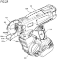
- Fig. 1A is an internal configuration diagram, seen from other side, illustrating an example of an overall configuration of a reinforcing bar binding machine according to an embodiment
- Fig. 1B is a front sectional view illustrating an example of the overall configuration of the reinforcing bar binding machine according to the embodiment.
- a reinforcing bar binding machine 1A has such a form that the operator holds it in his/her hand to use, and includes a main body 10A and a handle 11A. Further, the reinforcing bar binding machine 1A feeds a wire W in a positive direction as indicated by an arrow F to loop the wire W around reinforcing bars S that are the object to be bound, feeds the wire W looped around the reinforcing bars S in the reverse direction as indicated by an arrow R to wind the wire W on the reinforcing bars S and cuts the wire W, and then twists the wire W and binds the reinforcing bars S with the wire W.
- the reinforcing bar binding machine 1A includes a magazine 2A that houses the wire W, a wire feeder 3A that feeds the wire W, and a wire guide 4Athat guides the wire W to be fed to the wire feeder 3A. Further, the reinforcing bar binding machine 1A includes a curl forming part 5A forming a path for looping the wire W fed by the wire feeder 3A around the reinforcing bars S, and a cutter 6A that cuts the wire W wound on the reinforcing bars S. Further, the reinforcing bar binding machine 1A includes a binding part 7A that twists the wire W wound on the reinforcing bars S, and a driving part 8A that drives the binding part 7A.
- the magazine 2A is an example of a housing in which a reel 20 with a long wire W releasably wound thereon is rotatably and detachably housed.
- a wire made of a plastically deformable metal wire, a wire which is a metal wire coated with resin, or a stranded wire is used for the wire W.
- One or a plurality of wires W are wound on a hub portion (not illustrated) of the reel 20, such that one, or simultaneously a plurality of wires W can be pulled out from the reel 20.
- the reel 20 is attached to the magazine 2Ain a state of being offset in one direction with respect to the feeding path FL of the wire W defined by the wire guide 4A to be described below.
- the wire feeder 3A includes a pair of feed gears 30 that hold one or a plurality of wires W in parallel therebetween to feed the wires, and a feed motor 31 that drives the feed gears 30.
- the rotational movement of the feed motor 31 is transmitted via a transmission mechanism (not illustrated) to rotate the feed gears 30.
- the wire feeder 3A feeds the wire W held between the pair of feed gears 30 along an extending direction of the wire W.
- the two wires W are fed in parallel.
- the rotation direction of the feed gear 30 can be switched, and the feeding direction of the wire W is switched between the positive direction which is one direction, and the reverse direction which is the other direction opposite to the one direction.
- the wire guide 4A is provided at a predetermined position on the upstream side and the downstream side of the wire feeder 3A with respect to the feeding direction in which the wire W is fed in the positive direction. In a configuration in which two wires W are fed, the wire guide 4A restricts an orientation of the two wires W in a radial direction, arranges the two incoming wires W in parallel, and guides the wires between the pair of feed gears 30.
- the wire guide 4A has a shape such that an opening on the downstream side with respect to the feeding direction of the wire W fed in the positive direction restricts the orientation of the wire W in the radial direction.
- an opening on the upstream side with respect to the feeding direction of the wire W fed in the positive direction has a larger opening area than the opening on the downstream side.
- the curl forming part 5A includes a curl guide 50 that forms a winding curl with the wire W fed by the wire feeder 3A, and an draw-in guide 51 that guides the wire W formed with the winding curl by the curl guide 50 to the binding part 7A.
- the path of the wire W fed by the wire feeder 3A is restricted by the curl forming part 5A, so that the locus of the wire W forms a loop Ru as illustrated by a two-dot chain line in Fig. 1A , and the wire W is looped around the reinforcing bars S.
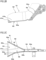
- Fig. 2A is an overall perspective view illustrating an example of the draw-in guide according to the embodiment
- Fig. 2B is a cross-sectional view illustrating a main part of the example of the draw-in guide according to the embodiment
- Fig. 2C is a plan view illustrating a main part of the example of the draw-in guide according to the embodiment
- the draw-in guide 51 is provided at a position offset in the other direction, which is the opposite direction to the one direction in which the reel 20 is offset with respect to the feeding path FL of the wire W defined by the wire guide 4A.
- the draw-in guide 51 includes a first guide 52 that restricts an axial position of the loop Ru formed by the wire W curled by the curl guide 50, and a second guide 53 and a third guide 54 that restrict a radial position of the loop Ru formed by the wire W.
- the first guide 52 and the second guide 53 are, relative to the third guide 54, provided on a side where the wire W curled by the curl guide 50 is introduced.
- the first guide 52 includes a side surface portion 52b on one side that is a side positioned in the one direction where the reel 20 is offset. Further, the first guide 52 includes, on the other side that is a side positioned in the opposite direction to the one direction where the reel 20 is offset, a side surface portion 52a facing the side surface portion 52b.
- the second guide 53 includes a bottom surface portion 53a connecting the side surface portion 52a and the side surface portion 52b, in which the side surface portion 52b is erected on one side and the side surface portion 52a is erected on the other side.
- the third guide 54 includes, on a radially outer side of the loop Ru formed by the wire W, a guide surface 54a which is a surface extending toward the binding part 7A along the feeding direction of the wire W.
- a converging path 55 is formed in a space surrounded by a pair of side surface portions 52a and 52b and the bottom surface portion 53a. Further, in the draw-in guide 51, an open end 55a, through which the wire W enters the converging path 55, is formed. The open end 55a is opened in the space surrounded by the pair of side surface portions 52a and 52b and the bottom surface portion 53a.
- a distance between the side surface portion 52a and the side surface portion 52b is widest at the open end 55a, and gradually narrows from the open end 55a toward the guide surface 54a of the third guide 54, and a narrowest portion 55b is formed.
- the draw-in guide 51 includes an entry angle restriction part 56 that changes the entry angle of the wire W entering the converging path 55 to direct the wire W toward the narrowest portion 55b.
- the reel 20 is disposed in the state of being offset in the one direction.
- the wire W which is fed from the reel 20 offset in the one direction by the wire feeder 3A and curled by the curl guide 50, is directed toward the other direction, which is the opposite direction to the one direction in which the reel 20 is offset.
- the wire W entering the converging path 55 between the side surface portion 52a and the side surface portion 52b of the first guide 52 first enters toward the side surface portion 52a.
- the leading end of the wire W entering toward the side surface portion 52a is directed toward the narrowest portion 55b of the converging path 55. Therefore, the entry angle restriction part 56 is provided on the side surface portion 52b facing the side surface portion 52a.
- the entry angle restriction part 56 is configured such that a portion of the side surface portion 52b at an approximately intermediate position in the entry direction of the wire W is in a projected shape in the direction of the side surface portion 52b.
- the draw-in guide 51 includes a guiding facilitation part 57a that comes into contact with the wire W from the radially outer side of the loop Ru that is formed by the wire W curled by the curl guide 50, and applies, to the wire W, a force that changes the feeding path of the wire W. Further, the draw-in guide 51 includes an guiding concave portion 57b into which the wire W, expanding toward the radially outer side of the loop Ru, enters between the guiding facilitation part 57a and the third guide 54.
- the guiding facilitation part 57a is configured by providing a convex portion protruding in the curl guide 50 direction on the bottom surface portion 53a of the second guide 53 formed of a flat surface.
- the guiding facilitation part 57a is provided on the open end 55a side from the center of the bottom surface portion 53a along the feeding direction of the wire W, and in this example, is provided along the open end 55a over the entire width thereof.
- the guiding facilitation part 57a is configured by integrating a convex member having a predetermined shape such as a triangular cross-sectional shape or the like with the bottom surface portion 53a, or by attaching a component separate from the bottom surface portion 53a to the bottom surface portion 53a. Further, the guiding facilitation part 57a may be formed of a rotating member such as a roller or the like which has a shaft extending along the open end 55a and which the wire W is able to contact with. The guiding facilitation part 57a is at a protruding height from the bottom surface portion 53a so as to avoid a contact with the leading end of the wire W that is curled by the curl guide 50 and guided by the draw-in guide 51.
- the guiding concave portion 57b is provided on the downstream side of the guiding facilitation part 57a with respect to the feed direction of the wire W fed in the positive direction, and is formed of the bottom surface portion 53a of the second guide 53 that is concave toward the radially outer side of the loop Ru formed by the wire W with respect to the guiding facilitation part 57a.
- the wire W curled by the curl guide 50 is introduced between the pair of side surface portions 52a and 52b of the first guide 52.
- the draw-in guide 51 is widen in a direction in which the diameter of the loop Ru formed by the wire W is increased, so that the wire W comes into contact with the guiding facilitation part 57a of the second guide 53 and the entry direction of the wire W can be changed.
- the wire W introduced between the pair of side surface portions 52a and 52b of the first guide 52 is guided to the third guide 54.
- the cutter 6A includes a fixed blade 60, a movable blade 61 that cuts the wire W in cooperation with the fixed blade 60, and a transmission mechanism 62 that transmits a movement of the binding part 7A to the movable blade 61.
- the cutter 6A cuts the wire W by the rotational movement of the movable blade 61 around the fixed blade 60 as a fulcrum axis.
- the binding part 7A includes the wire locking body 70 to which the wire W is locked, and a rotating shaft 72 for operating the wire locking body 70.
- the driving part 8A includes a motor 80 and a speed reducer 81 that decreases speed and amplifies torque.
- the rotating shaft 72 and the motor 80 are connected via the speed reducer 81, and the rotating shaft 72 is driven by the motor 80 via the speed reducer 81.
- the curl guide 50 and the draw-in guide 51 of the curl forming part 5A described above are provided at a front end of the main body 10A, which is one side of the rotating shaft 72 along the axial direction.
- the reinforcing bar binding machine 1A includes a feed restriction part 90 to be contacted with a leading end of the wire W, on the feeding path of the wire W that is guided by the curl forming part 5A and locked by the wire locking body 70.
- a contacting portion 91 to be contacted with the reinforcing bars S is provided at a front end of the main body 10A between the curl guide 50 and the draw-in guide 51.
- the handle 11A extends downward from the main body 10A. Further, a battery 15A is detachably attached to a lower portion of the handle 11A. Further, in the reinforcing bar binding machine 1A, the magazine 2A is provided in front of the handle 11A. In the reinforcing bar binding machine 1A, the wire feeder 3A, the cutter 6A, the binding part 7A, the driving part 8A for driving the binding part 7A, and the like described above are housed in the main body 10A.
- a trigger 12A is provided on a front side of the handle 11A, and a switch 13A is provided inside the handle 11A.
- a control unit 14A controls the motor 80 and the feed motor 31 according to the state of the switch 13A pressed by the operation of the trigger 12A.
- Fig. 3A is a side view illustrating the configuration of the main part of the reinforcing bar binding machine according to the embodiment
- Fig. 3B is a top view illustrating the configuration of the main part of the reinforcing bar binding machine according to the embodiment
- Fig. 3C is a top sectional view illustrating the configuration of the main part of the reinforcing bar binding machine according to the embodiment.
- the binding part 7A includes the wire locking body 70 to which the wire W is locked, and a rotating shaft 72 for operating the wire locking body 70.
- the rotating shaft 72 and the motor 80 are connected via the speed reducer 81, and the rotating shaft 72 is driven by the motor 80 via the speed reducer 81.
- the wire locking body 70 includes a center hook 70C connected to the rotating shaft 72, a first side hook 70L and a second side hook 70R that are opened and closed with respect to the center hook 70C, and a sleeve 71 that operates the first side hook 70L and the second side hook 70R in conjunction with the rotational movement of the rotating shaft 72.
- the binding part 7A may be divided into a front side where the center hook 70C, the first side hook 70L, and the second side hook 70R are provided, and a rear side where the rotating shaft 72 is connected to the speed reducer 81.
- the center hook 70C is connected to the front end, which is one end of the rotating shaft 72, via a configuration that enables rotation with respect to the rotating shaft 72 and also enables movement in the axial direction integrally with the rotating shaft 72.
- the leading end side of the first side hook 70L which is one end along the axial direction of the rotating shaft 72, is positioned on one side with respect to the center hook 70C. Further, the rear end side of the first side hook 70L, which is the other end along the axial direction of the rotating shaft 72, is rotatably supported by the center hook 70C by a shaft 71b.
- the leading end side of the second side hook 70R which is one end along the axial direction of the rotating shaft 72, is positioned on the other side with respect to the center hook 70C. Further, the rear end side of the second side hook 70R, which is the other end along the axial direction of the rotating shaft 72, is rotatably supported by the center hook 70C by the shaft 71b.
- the wire locking body 70 is opened and closed in a direction in which the leading end side of the first side hook 70L separates away from and approaches the center hook 70C by the rotational movement about the shaft 71b as the fulcrum. Further, the leading end side of the second side hook 70R is opened and closed in a direction in which the leading end side separates away from and approaches the center hook 70C.
- the rotating shaft 72 is connected to the speed reducer 81 at a rear end, which is the other end, via a connecting part 72b having a configuration that is integrally rotatable with the speed reducer 81 and is also movable in the axial direction with respect to the speed reducer 81.
- the connecting part 72b includes a spring 72c that biases the rotating shaft 72 rearward, which is a direction of approaching the speed reducer 81, and restricts the position of the rotating shaft 72 along the axial direction.
- the rotating shaft 72 is configured such that, by the force pushing rearward applied by the spring 72c, the rotating shaft 72 is movable forward, that is, movable in a direction of separating away from the speed reducer 81. Therefore, upon application of the force that moves the wire locking body 70 forward along the axial direction, the rotating shaft 72 is movable forward by the force pushing rearward applied by the spring 72c.
- the sleeve 71 is shaped such that a range of a predetermined length from the end at the forward direction indicated by an arrow A1 along the axial direction of the rotating shaft 72 is divided into two parts in the radial direction, receiving therein the first side hook 70L and the second side hook 70R in openable and closable manner. Further, the sleeve 71 has a cylindrical shape that covers the circumference of the rotating shaft 72, and includes a convex portion (not illustrated) protruding from an inner peripheral surface of a tubular space where the rotating shaft 72 is inserted, in which the convex portion enters a groove portion of a feed screw 72a formed along the axial direction on the outer periphery of the rotating shaft 72.
- the sleeve 71 When the rotating shaft 72 is rotated, the sleeve 71 is moved in the forward and rearward direction, which is a direction along the axial direction of the rotating shaft 72, according to the rotation direction of the rotating shaft 72 by the action of the convex portion (not illustrated) and the feed screw 72a of the rotating shaft 72. Further, the sleeve 71 is rotated integrally with the rotating shaft 72.
- the sleeve 71 includes an opening and closing pin 71a for opening and closing the first side hook 70L and the second side hook 70R.
- the opening and closing pin 71a is inserted into an opening and closing guide hole 73 provided in the first side hook 70L and the second side hook 70R.
- the opening and closing guide hole 73 extends along a moving direction of the sleeve 71, and has a shape that converts the linear movement of the opening and closing pin 71a that is moved in conjunction with the sleeve 71 into an opening and closing movement by the rotation of the first side hook 70L and the second side hook 70R about the shaft 71b as a fulcrum.
- the first side hook 70L and the second side hook 70R are moved in the direction of separating away from the center hook 70C by the rotational movement about the shaft 71b as a fulcrum.
- the first side hook 70L and the second side hook 70R are opened with respect to the center hook 70C, and the feeding path for the wire W to pass through is formed between the first side hook 70L and the center hook 70C, and between the second side hook 70R and the center hook 70C.
- the wire W fed by the wire feeder 3A is passed between the center hook 70C and the first side hook 70L.
- the wire W passed between the center hook 70C and the first side hook 70L is guided to the curl forming part 5A.
- the wire W formed with the winding curl by the curl forming part 5A and guided to the binding part 7A is passed between the center hook 70C and the second side hook 70R.
- the first side hook 70L and the second side hook 70R are moved in a direction of approaching the center hook 70C by the rotational movement about the shaft 71b as a fulcrum.
- the first side hook 70L and the second side hook 70R are closed with respect to the center hook 70C.
- the wire W held between the first side hook 70L and the center hook 70C is locked in a movable form between the first side hook 70L and the center hook 70C.
- the wire W held between the second side hook 70R and the center hook 70C is locked in such a form that the wire W does not come off from between the second side hook 70R and the center hook 70C.
- the wire locking body 70 includes a bending part 71c1 that pushes the leading end side, which is one end of the wire W, in a predetermined direction and bends the wire W to form the wire W into a predetermined shape.
- the wire locking body 70 includes a bending part 71c2 that pushes an end side, which is the other end of the wire W cut by the cutter 6A, in a predetermined direction and bends the wire W to form the wire W into a predetermined shape.
- the sleeve 71 has such a shape that the end at the forward direction as indicated by the arrow A1 is divided into two parts of the first side hook 70L and the second side hook 70R with the center hook 70C held therebetween, and includes the bending part 71c1 formed at the front end at a position on an upper side in the non-rotating region, and the bending part 71c2 formed at the front end at a position on a lower side.
- the sleeve 71 is moved in the forward direction as indicated by the arrow A1 so that the leading end side of the wire W locked by the center hook 70C and the second side hook 70R is pushed by the bending part 71c1 and bent toward the reinforcing bars S side. Further, the sleeve 71 is locked by the center hook 70C and the first side hook 70L, and the end side of the wire W cut by the cutter 6A is pushed by the bending part 71c2 and bent toward the reinforcing bars S side.
- the binding part 7A includes a rotation restriction part 74 that restricts the rotation of the wire locking body 70 and the sleeve 71 that are rotated in conjunction with the rotational movement of the rotating shaft 72.
- the rotation restriction part 74 is provided with a rotation restriction blade 74a on the sleeve 71 and is provided with a rotation restriction claw 74b on the main body 10A.
- the rotation restriction blade 74a is configured by providing a plurality of convex portions radially protruding from the outer periphery of the sleeve 71 at predetermined intervals in the circumferential direction of the sleeve 71.
- the rotation restriction blade 74a is fixed to the sleeve 71 and is moved and rotated integrally with the sleeve 71.
- the rotation restriction part 74 locks the wire W with the wire locking body 70, winds the wire W on the reinforcing bars S, and then cuts the wire W with the cutter 6A, and further, the rotation restriction blade 74a is locked to the rotation restriction claw 74b in the operating range in which the wire W is bent and formed by the bending parts 71c1 and 71c2 of the sleeve 71.
- the rotation restriction blade 74a is locked with the rotation restriction claw 74b, the rotation of the sleeve 71 in conjunction with the rotation of the rotating shaft 72 is restricted, and the sleeve 71 is moved in the forward and rearward direction by the rotational movement of the rotating shaft 72.
- the rotation restriction part 74 is released from being locked with the rotation restriction claw 74b of the rotation restriction blade 74a.
- the rotation restriction blade 74a is released from being locked with the rotation restriction claw 74b, the sleeve 71 is rotated in conjunction with the rotation of the rotating shaft 72.
- the center hook 70C, the first side hook 70L, and the second side hook 70R that lock the wire W are rotated in conjunction with the rotation of the sleeve 71.
- the operating range in which the wire W is locked by the wire locking body 70 is referred to as a first operating range. Further, the operating range for twisting the wire W locked by the wire locking body 70 in the first operating range is referred to as a second operating range.
- the binding part 7A is provided such that a moving member 83 is movable in conjunction with the sleeve 71.
- the moving member 83 is rotatably attached to the sleeve 71, is not in conjunction with the rotation of the sleeve 71, and is moved in the forward and rearward direction in conjunction with the sleeve 71.
- the moving member 83 includes an engagement part 83a that engages with the transmission mechanism 62.
- the transmission mechanism 62 transmits the movement of the moving member 83 to the movable blade 61 to rotate the movable blade 61.
- the movable blade 61 is rotated in a predetermined direction by the movement of the sleeve 71 moving in the forward direction, and the wire W is cut.
- the binding part 7A includes a tension applying spring 92 so that binding can be performed while tension is applied on the wire W.
- the tension applying spring 92 is provided outside the sleeve 71, and biases the sleeve 71 and the wire locking body 70 in the direction of separating away from the contacting portion 91 along the axial direction of the rotating shaft 72.
- the tension applying spring 92 is formed of, for example, a coil spring that expands and contracts in the axial direction, and is fitted on the outer periphery of the sleeve 71 between the rotation restriction blade 74a and a support frame 76d that rotatably and axially slidably supports the sleeve 71.
- the tension applying spring 92 is compressed between the support frame 76d and the rotation restriction blade 74a according to the position of the sleeve 71 along the axial direction of the rotating shaft 72, and biases the sleeve 71 rearward, which is the direction of separating away from the contacting portion 91 along the axial direction of the rotating shaft 72.
- the tension applying spring 92 biases the wire locking body 70 provided with the sleeve 71 in the direction of maintaining the tension applied to the wire W with the movement of feeding the wire W in the reverse direction and winding the wire W on the reinforcing bar S.
- the tension applying spring 92 applies tension to the wire W that is cut by the cutter 6A after wound on the reinforcing bar S with a larger force than the force applied in the direction in which the wire W wound on the reinforcing bars S loosens. Therefore, it is possible to bind the wire W after cutting while applying tension thereto.
- the wire locking body 70 is configured to be movable forward as the sleeve 71 is applied with the force pushing rearward by the tension applying spring 92 and also as the rotating shaft 72 is applied with the force pushing rearward by the spring 72c.
- the reinforcing bars S are bound with a plurality of wires W, such as two wires W for example, the two wires W are fed in parallel along the axial direction of the loop Ru formed by these wires W by the wire guide 4A.
- the wires W fed in the positive direction are passed between the center hook 70C and the first side hook 70L and are fed to the curl guide 50 of the curl forming part 5A.
- the wire W is formed with a winding curl that is looped around the reinforcing bars S.
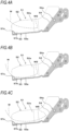
- Figs. 4A, 4B and 4C are explanatory diagrams illustrating the movement of the wire in the draw-in guide. The action and effect of inducing the wire W with the draw-in guide 51 will be described below.
- the wire W curled by the curl guide 50 and guided into the draw-in guide 51 is passed through a path separate from the bottom surface portion 53a of the second guide 53 in the draw-in guide 51. Further, the wire W curled by the curl guide 50 is directed to the other direction, which is the opposite direction to the one direction in which the reel 20 is offset. Therefore, in the draw-in guide 51, the wire W entering between the side surface portion 52a and the side surface portion 52b of the first guide 52 first enters toward the side surface portion 52a.
- the wire W guided into the draw-in guide 51 can follow a path to enter the guiding concave portion 57b to a position in contact with the bottom surface portion 53a of the second guide 53.
- the wire W is guided by the draw-in guide 51 so that the leading end WS comes into contact with the side surface portion 52a
- the wire W is already applied with a force that changes the feeding path of the wire W entering toward the side surface portion 52a, by a contact with the entry angle restriction part 56, before coming into contact with the guiding facilitation part 57a.
- the wire W guided into the draw-in guide 51 can be guided so that the leading end WS is guided in the direction away from the side surface portion 52a and introduced into the narrowest portion 55b toward the third guide 54b.
- the wire W formed with the winding curl by the curl guide 50 is guided to the draw-in guide 51 and further fed by the wire feeder 3A in the positive direction, and guided between the center hook 70C and the second side hook 70R by the draw-in guide 51. Then, the wire W is fed until the leading end thereof is brought into contact with the feed restriction part 90. When the wire W is fed to a position where the leading end thereof is brought into contact with the feed restriction part 90, driving of the feed motor 31 is stopped.
- the motor 80 After stopping feeding the wire W in the positive direction, the motor 80 is driven in the forward rotation direction.
- the rotation restriction blade 74a is locked to the rotation restriction claw 74b, so that the rotation of the sleeve 71 in conjunction with the rotation of the rotating shaft 72 is restricted.
- the rotation of the motor 80 is converted into linear movement, and the sleeve 71 is moved in the direction of the arrow A1 which is the forward direction.
- the opening and closing pin 71a is passed through the opening and closing guide hole 73.
- the first side hook 70L is moved in a direction of approaching the center hook 70C by the rotational movement about the shaft 71b as the fulcrum.
- the wire W held between the first side hook 70L and the center hook 70C is locked in a movable form between the first side hook 70L and the center hook 70C.
- the second side hook 70R is moved in the direction of approaching the center hook 70C by the rotational movement about the shaft 71b as a fulcrum.
- the wire W held between the second side hook 70R and the center hook 70C is locked in such a form that the wire W does not come off from between the second side hook 70R and the center hook 70C.
- the pair of feed gears 30 are reversed, and the wire W held between the pair of feed gears 30 is fed in the opposite direction as indicated by the arrow R. Since the leading end side of the wire W is locked in a form so as not to come off between the second side hook 70R and the center hook 70C, the wire W is wound on the reinforcing bars S by the movement of feeding the wire W in the opposite direction.
- the movement of the sleeve 71 in the forward direction is transmitted to the cutter 6A by the transmission mechanism 62, so that the movable blade 61 is rotated, and the wire W locked by the first side hook 70L and the center hook 70C is cut by the operation of the fixed blade 60 and the movable blade 61.
- the rotation restriction blade 74a comes into contact with the tension applying spring 92, and the tension applying spring 92 is compressed between the support frame 76d and the rotation restriction blade 74a, so that the sleeve 71 and the wire locking body 70 are biased rearward by the tension applying spring 92.
- the sleeve 71 By driving the motor 80 in the forward rotation direction, the sleeve 71 is moved in the forward direction as indicated by the arrow A1, and almost simultaneously with cutting the wire W, the bending part 71c1 is moved in the direction of approaching the reinforcing bars S. As a result, the leading end side of the wire W locked by the center hook 70C and the second side hook 70R is pressed toward the reinforcing bars S side by the bending part 71c1 and bent toward the reinforcing bars S side about the locking position as a fulcrum. By further moving the sleeve 71 forward, the wire W locked between the second side hook 70R and the center hook 70C is held in a state of being held by the bending part 71c1.
- the wire W is held between the first wire holding part 71c2a and the second wire holding part 71c2b forming the bending part 71c2 of the sleeve 71 and the come-off prevention part 70La of the first side hook 70L, and the end side of the wire W cut by the cutter 6Ais further pressed toward the reinforcing bar S side by the bending part 71c2, and bent toward the reinforcing bar S side about the locking position as a fulcrum.
- the wire W locked between the first side hook 70L and the center hook is held in a state of being held between the bending part 71c2.
- the motor 80 After bending the leading end side and the end side of the wire W toward the reinforcing bars S side, the motor 80 is further driven in the forward rotation direction, so that the sleeve 71 is moved further forward.
- the rotation restriction blade 74a is released from being locked with the rotation restriction claw 74b.
- the wire locking body 70 is subjected to a force that pulls forward along the axial direction of the rotating shaft 72. Meanwhile, moving the sleeve 71 forward to a position where the sleeve 71 is rotatable causes the tension applying spring 92 to be further compressed, and the sleeve 71 receives the force pushing rearward applied by the tension applying spring 92.
- the sleeve 71 receives the force pushing rearward applied by the tension applying spring 92, and also, the rotating shaft 72 is moved forward while receiving the force pushing rearward applied by the spring 72c, and twists the wire W while being moved forward.
- the wire W locked by the wire locking body 70 is pulled rearward and the tension is applied in the tangential direction of the reinforcing bars S, the wire W is pulled so as to be in close contact with the reinforcing bars S.
- the wire locking body 70 in a second operating range in which the sleeve 71 is rotated and twists the wire W, when the wire locking body 70 is further rotated in conjunction with the rotating shaft 72, the wire locking body 70 and the rotating shaft 72 are moved in the forward direction which is the direction of decreasing a gap between the twisted portion of the wire W and the reinforcing bars S, resulting in the wire W being further twisted.
- the wire W is twisted as the wire locking body 70 and the rotating shaft 72 are moved forward while receiving the force pushing rearward applied by the tension applying spring 92 and the spring 72c, so that the gap between the twisted portion of the wire W and the reinforcing bars S is decreased, and the wire W comes into close contact with the reinforcing bars S and in a form that conforms to the reinforcing bars S.
- the loosening of the wire W before twisting can be removed, and the wire W can be bound in a state of being in close contact with the reinforcing bars S.
- the forward rotation of the motor 80 is stopped. Then, by driving the motor 80 in the reverse rotation direction, the rotating shaft 72 is rotated in the reverse direction, and the sleeve 71 is rotated in the reverse direction following the reverse rotation of the rotating shaft 72, such that the rotation restriction blade 74a is locked with the rotation restriction claw 74b, thus restricting the rotation of the sleeve 71 in conjunction with the rotation of the rotating shaft 72. As a result, the sleeve 71 is moved in the direction of the arrow A2 which is the rearward direction.
- the bending parts 71c1 and 71c2 are separated from the wire W, and the wire W held by the bending parts 71c1 and 71c2 is released. Further, when the sleeve 71 is moved in the rearward direction, the opening and closing pin 71a is passed through the opening and closing guide hole 73. As a result, the first side hook 70L is moved in a direction of separating away from the center hook 70C by the rotational movement about the shaft 71b as a fulcrum. Further, the second side hook 70R is moved in a direction of separating away from the center hook 70C by the rotational movement about the shaft 71b as a fulcrum. As a result, the wire W comes off from the wire locking body 70.
Description
- The present disclosure relates to a binding machine for binding an object to be bound such as a reinforcing bar or the like with a wire.
- A binding machine called a reinforcing bar binding machine has been proposed, which winds a wire around two or more reinforcing bars and twists the wire wound on the reinforcing bars to thus bind the two or more reinforcing bars with the wire.
- The binding machine sends the wire fed by the driving force of a motor through a guide called a curl guide or the like to curl the wire and wind around the reinforcing bar. The curled wire is guided to a binding part that twists the wire, by a guide called an draw-in guide, and the like, and the wire wound around the reinforcing bar is twisted by the binding part, so that the reinforcing bar is bound with the wire.
- The guide that guides the curled wire to the binding part has a shape in which a distance between a pair of wall surfaces gradually narrows from a leading end side where the wire is advanced toward the rear end side (see, for example, International Publication No.
WO2017/014270 ). As a result, when entering the guide that guides the curled wire to the binding part, the wire is guided along the pair of wall surfaces between which the distance is gradually narrowed. - When the entry angle of the wire entering the guide that guides the wire to the binding part is increased, the angle at which the wire comes into contact with the wall surface is increased when the leading end of the wire comes into contact with one of the pair of wall surfaces. When the contact angle of the wire with respect to the wall surface is increased, the resistance due to friction of the wire sliding along the wall surface is increased, and the wire cannot be fed. Further,
US 2020/290759 A1 discloses a binding machine with the features of the preamble ofclaim 1. - The present disclosure has been made in order to solve such a problem, and it is an object of the present invention to provide a binding machine capable of reliably feeding a wire regardless of the entry angle of the wire.
- According to the invention according to
claim 1, there is provided a binding machine including: a wire feeder configured to feed a wire to be wound around an object to be bound; a binding part configured to twist the wire wound around the object to be bound; a curl guide configured to curl the wire fed by the wire feeder; and an draw-in guide configured to guide the wire curled by the curl guide to the binding part, in which the draw-in guide includes a guiding facilitation part that comes into contact with the wire from a radially outer side of a loop that is formed by the wire curled by the curl guide, and applies, to the wire, a force that changes a feeding path of the wire, and a guiding concave portion, provided on a downstream side of the guiding facilitation part in a feeding direction of the wire, into which the wire, expanding toward the radially outer side of the loop, enters. - According to the embodiment of the present disclosure, the wire guided into the draw-in guide expands in the direction in which the diameter of the loop is gradually increased and enters the guiding concave portion, thus coming into contact with the guiding facilitation part on the upstream side of the guiding concave portion in the feeding direction of the wire.
- When the wire guided by the draw-in guide comes into contact with the guiding facilitation part, a force that changes the feeding path of the wire acts on the wire.
- As a result, the wire can be guided to the binding part regardless of the entry angle of the wire entering the draw-in guide.
-
-
Fig. 1A is an internal configuration diagram, seen from other side, illustrating an example of an overall configuration of a reinforcing bar binding machine according to an embodiment; -
Fig. 1B is a front sectional view illustrating an example of the overall configuration of the reinforcing bar binding machine according to the embodiment; -
Fig. 2A is an overall perspective view illustrating an example of an draw-in guide according to the embodiment; -
Fig. 2B is a cross-sectional view illustrating a main part of the example of the draw-in guide according to the embodiment; -
Fig. 2C is a plan view illustrating a main part of the example of the draw-in guide according to the embodiment; -
Fig. 3A is a side view illustrating a configuration of a main part of the reinforcing bar binding machine according to the embodiment; -
Fig. 3B is a top view illustrating the configuration of the main part of the reinforcing bar binding machine according to the embodiment; -
Fig. 3C is a top sectional view illustrating the configuration of the main part of the reinforcing bar binding machine according to the embodiment; -
Fig. 4A is an explanatory diagram illustrating a movement of a wire in the draw-in guide; -
Fig. 4B is an explanatory diagram illustrating the movement of the wire in the draw-in guide; and -
Fig. 4C is an explanatory diagram illustrating the movement of the wire in the draw-in guide. - Hereinafter, an example of a reinforcing bar binding machine as an embodiment of the binding machine according to the present invention will be described with reference to the drawings.
-
Fig. 1A is an internal configuration diagram, seen from other side, illustrating an example of an overall configuration of a reinforcing bar binding machine according to an embodiment, andFig. 1B is a front sectional view illustrating an example of the overall configuration of the reinforcing bar binding machine according to the embodiment. - A reinforcing bar binding machine 1A has such a form that the operator holds it in his/her hand to use, and includes a
main body 10A and ahandle 11A. Further, the reinforcing bar binding machine 1A feeds a wire W in a positive direction as indicated by an arrow F to loop the wire W around reinforcing bars S that are the object to be bound, feeds the wire W looped around the reinforcing bars S in the reverse direction as indicated by an arrow R to wind the wire W on the reinforcing bars S and cuts the wire W, and then twists the wire W and binds the reinforcing bars S with the wire W. - In order to achieve the functions mentioned above, the reinforcing bar binding machine 1A includes a
magazine 2A that houses the wire W, awire feeder 3A that feeds the wire W, and a wire guide 4Athat guides the wire W to be fed to thewire feeder 3A. Further, the reinforcing bar binding machine 1A includes acurl forming part 5A forming a path for looping the wire W fed by thewire feeder 3A around the reinforcing bars S, and a cutter 6A that cuts the wire W wound on the reinforcing bars S. Further, the reinforcing bar binding machine 1A includes abinding part 7A that twists the wire W wound on the reinforcing bars S, and a drivingpart 8A that drives thebinding part 7A. - The
magazine 2A is an example of a housing in which areel 20 with a long wire W releasably wound thereon is rotatably and detachably housed. For the wire W, a wire made of a plastically deformable metal wire, a wire which is a metal wire coated with resin, or a stranded wire is used. One or a plurality of wires W are wound on a hub portion (not illustrated) of thereel 20, such that one, or simultaneously a plurality of wires W can be pulled out from thereel 20. - As illustrated in
Fig. 1B , thereel 20 is attached to the magazine 2Ain a state of being offset in one direction with respect to the feeding path FL of the wire W defined by thewire guide 4A to be described below. - The
wire feeder 3A includes a pair offeed gears 30 that hold one or a plurality of wires W in parallel therebetween to feed the wires, and afeed motor 31 that drives thefeed gears 30. In thewire feeder 3A, the rotational movement of thefeed motor 31 is transmitted via a transmission mechanism (not illustrated) to rotate thefeed gears 30. - As a result, the
wire feeder 3A feeds the wire W held between the pair offeed gears 30 along an extending direction of the wire W. In a configuration in which a plurality of wires W such as, for example, two wires W are fed, the two wires W are fed in parallel. - In the
wire feeder 3A, by switching between forward and reverse rotation directions of thefeed motor 31, the rotation direction of thefeed gear 30 can be switched, and the feeding direction of the wire W is switched between the positive direction which is one direction, and the reverse direction which is the other direction opposite to the one direction. - The
wire guide 4A is provided at a predetermined position on the upstream side and the downstream side of thewire feeder 3A with respect to the feeding direction in which the wire W is fed in the positive direction. In a configuration in which two wires W are fed, thewire guide 4A restricts an orientation of the two wires W in a radial direction, arranges the two incoming wires W in parallel, and guides the wires between the pair offeed gears 30. - The
wire guide 4A has a shape such that an opening on the downstream side with respect to the feeding direction of the wire W fed in the positive direction restricts the orientation of the wire W in the radial direction. On the other hand, an opening on the upstream side with respect to the feeding direction of the wire W fed in the positive direction has a larger opening area than the opening on the downstream side. - The
curl forming part 5A includes acurl guide 50 that forms a winding curl with the wire W fed by thewire feeder 3A, and an draw-inguide 51 that guides the wire W formed with the winding curl by thecurl guide 50 to thebinding part 7A. In the reinforcing bar binding machine 1A, the path of the wire W fed by thewire feeder 3A is restricted by thecurl forming part 5A, so that the locus of the wire W forms a loop Ru as illustrated by a two-dot chain line inFig. 1A , and the wire W is looped around the reinforcing bars S. -
Fig. 2A is an overall perspective view illustrating an example of the draw-in guide according to the embodiment,Fig. 2B is a cross-sectional view illustrating a main part of the example of the draw-in guide according to the embodiment,Fig. 2C is a plan view illustrating a main part of the example of the draw-in guide according to the embodiment, and the draw-inguide 51 of the embodiment will be described below. The draw-inguide 51 is provided at a position offset in the other direction, which is the opposite direction to the one direction in which thereel 20 is offset with respect to the feeding path FL of the wire W defined by thewire guide 4A. - The draw-in
guide 51 includes afirst guide 52 that restricts an axial position of the loop Ru formed by the wire W curled by thecurl guide 50, and asecond guide 53 and athird guide 54 that restrict a radial position of the loop Ru formed by the wire W. - The
first guide 52 and thesecond guide 53 are, relative to thethird guide 54, provided on a side where the wire W curled by thecurl guide 50 is introduced. - The
first guide 52 includes aside surface portion 52b on one side that is a side positioned in the one direction where thereel 20 is offset. Further, thefirst guide 52 includes, on the other side that is a side positioned in the opposite direction to the one direction where thereel 20 is offset, aside surface portion 52a facing theside surface portion 52b. - The
second guide 53 includes abottom surface portion 53a connecting theside surface portion 52a and theside surface portion 52b, in which theside surface portion 52b is erected on one side and theside surface portion 52a is erected on the other side. - The
third guide 54 includes, on a radially outer side of the loop Ru formed by the wire W, aguide surface 54a which is a surface extending toward thebinding part 7A along the feeding direction of the wire W. - In the draw-in
guide 51, a convergingpath 55 is formed in a space surrounded by a pair ofside surface portions bottom surface portion 53a. Further, in the draw-inguide 51, anopen end 55a, through which the wire W enters the convergingpath 55, is formed. Theopen end 55a is opened in the space surrounded by the pair ofside surface portions bottom surface portion 53a. - In the
first guide 52, a distance between theside surface portion 52a and theside surface portion 52b is widest at theopen end 55a, and gradually narrows from theopen end 55a toward theguide surface 54a of thethird guide 54, and anarrowest portion 55b is formed. - The draw-in
guide 51 includes an entryangle restriction part 56 that changes the entry angle of the wire W entering the convergingpath 55 to direct the wire W toward thenarrowest portion 55b. - In the reinforcing bar binding machine 1A, the
reel 20 is disposed in the state of being offset in the one direction. The wire W, which is fed from thereel 20 offset in the one direction by thewire feeder 3A and curled by thecurl guide 50, is directed toward the other direction, which is the opposite direction to the one direction in which thereel 20 is offset. - Therefore, the wire W entering the converging
path 55 between theside surface portion 52a and theside surface portion 52b of thefirst guide 52 first enters toward theside surface portion 52a. The leading end of the wire W entering toward theside surface portion 52a is directed toward thenarrowest portion 55b of the convergingpath 55. Therefore, the entryangle restriction part 56 is provided on theside surface portion 52b facing theside surface portion 52a. - The entry
angle restriction part 56 is configured such that a portion of theside surface portion 52b at an approximately intermediate position in the entry direction of the wire W is in a projected shape in the direction of theside surface portion 52b. - The draw-in
guide 51 includes a guidingfacilitation part 57a that comes into contact with the wire W from the radially outer side of the loop Ru that is formed by the wire W curled by thecurl guide 50, and applies, to the wire W, a force that changes the feeding path of the wire W. Further, the draw-inguide 51 includes an guidingconcave portion 57b into which the wire W, expanding toward the radially outer side of the loop Ru, enters between the guidingfacilitation part 57a and thethird guide 54. - The guiding
facilitation part 57a is configured by providing a convex portion protruding in thecurl guide 50 direction on thebottom surface portion 53a of thesecond guide 53 formed of a flat surface. The guidingfacilitation part 57a is provided on theopen end 55a side from the center of thebottom surface portion 53a along the feeding direction of the wire W, and in this example, is provided along theopen end 55a over the entire width thereof. - The guiding
facilitation part 57a is configured by integrating a convex member having a predetermined shape such as a triangular cross-sectional shape or the like with thebottom surface portion 53a, or by attaching a component separate from thebottom surface portion 53a to thebottom surface portion 53a. Further, the guidingfacilitation part 57a may be formed of a rotating member such as a roller or the like which has a shaft extending along theopen end 55a and which the wire W is able to contact with. The guidingfacilitation part 57a is at a protruding height from thebottom surface portion 53a so as to avoid a contact with the leading end of the wire W that is curled by thecurl guide 50 and guided by the draw-inguide 51. - The guiding
concave portion 57b is provided on the downstream side of the guidingfacilitation part 57a with respect to the feed direction of the wire W fed in the positive direction, and is formed of thebottom surface portion 53a of thesecond guide 53 that is concave toward the radially outer side of the loop Ru formed by the wire W with respect to the guidingfacilitation part 57a. - The wire W curled by the
curl guide 50 is introduced between the pair ofside surface portions first guide 52. The draw-inguide 51 is widen in a direction in which the diameter of the loop Ru formed by the wire W is increased, so that the wire W comes into contact with the guidingfacilitation part 57a of thesecond guide 53 and the entry direction of the wire W can be changed. As a result, the wire W introduced between the pair ofside surface portions first guide 52 is guided to thethird guide 54. - The cutter 6A includes a fixed
blade 60, amovable blade 61 that cuts the wire W in cooperation with the fixedblade 60, and atransmission mechanism 62 that transmits a movement of thebinding part 7A to themovable blade 61. The cutter 6A cuts the wire W by the rotational movement of themovable blade 61 around the fixedblade 60 as a fulcrum axis. - The
binding part 7A includes thewire locking body 70 to which the wire W is locked, and arotating shaft 72 for operating thewire locking body 70. The drivingpart 8A includes amotor 80 and aspeed reducer 81 that decreases speed and amplifies torque. In thebinding part 7A and thedriver 8A, the rotatingshaft 72 and themotor 80 are connected via thespeed reducer 81, and therotating shaft 72 is driven by themotor 80 via thespeed reducer 81. - In the reinforcing bar binding machine 1A, the
curl guide 50 and the draw-inguide 51 of thecurl forming part 5A described above are provided at a front end of themain body 10A, which is one side of therotating shaft 72 along the axial direction. Further, the reinforcing bar binding machine 1A includes afeed restriction part 90 to be contacted with a leading end of the wire W, on the feeding path of the wire W that is guided by thecurl forming part 5A and locked by thewire locking body 70. Further, in the reinforcing bar binding machine 1A, a contactingportion 91 to be contacted with the reinforcing bars S is provided at a front end of themain body 10A between thecurl guide 50 and the draw-inguide 51. - In the reinforcing bar binding machine 1A, the
handle 11A extends downward from themain body 10A. Further, abattery 15A is detachably attached to a lower portion of thehandle 11A. Further, in the reinforcing bar binding machine 1A, themagazine 2A is provided in front of thehandle 11A. In the reinforcing bar binding machine 1A, thewire feeder 3A, the cutter 6A, thebinding part 7A, the drivingpart 8A for driving thebinding part 7A, and the like described above are housed in themain body 10A. - In the reinforcing bar binding machine 1A, a
trigger 12A is provided on a front side of thehandle 11A, and aswitch 13A is provided inside thehandle 11A. In the reinforcing bar binding machine 1A, acontrol unit 14A controls themotor 80 and thefeed motor 31 according to the state of theswitch 13A pressed by the operation of thetrigger 12A. -
Fig. 3A is a side view illustrating the configuration of the main part of the reinforcing bar binding machine according to the embodiment,Fig. 3B is a top view illustrating the configuration of the main part of the reinforcing bar binding machine according to the embodiment, andFig. 3C is a top sectional view illustrating the configuration of the main part of the reinforcing bar binding machine according to the embodiment. Then, the details of thebinding part 7A and the connecting structure of thebinding part 7A and thedriver 8A will be described with reference to each drawing. - The
binding part 7A includes thewire locking body 70 to which the wire W is locked, and arotating shaft 72 for operating thewire locking body 70. In thebinding part 7A and the drivingpart 8A, the rotatingshaft 72 and themotor 80 are connected via thespeed reducer 81, and therotating shaft 72 is driven by themotor 80 via thespeed reducer 81. - The
wire locking body 70 includes acenter hook 70C connected to therotating shaft 72, afirst side hook 70L and asecond side hook 70R that are opened and closed with respect to thecenter hook 70C, and asleeve 71 that operates thefirst side hook 70L and thesecond side hook 70R in conjunction with the rotational movement of therotating shaft 72. - The
binding part 7A may be divided into a front side where thecenter hook 70C, thefirst side hook 70L, and thesecond side hook 70R are provided, and a rear side where the rotatingshaft 72 is connected to thespeed reducer 81. - The
center hook 70C is connected to the front end, which is one end of therotating shaft 72, via a configuration that enables rotation with respect to therotating shaft 72 and also enables movement in the axial direction integrally with the rotatingshaft 72. - The leading end side of the
first side hook 70L, which is one end along the axial direction of therotating shaft 72, is positioned on one side with respect to thecenter hook 70C. Further, the rear end side of thefirst side hook 70L, which is the other end along the axial direction of therotating shaft 72, is rotatably supported by thecenter hook 70C by ashaft 71b. - The leading end side of the
second side hook 70R, which is one end along the axial direction of therotating shaft 72, is positioned on the other side with respect to thecenter hook 70C. Further, the rear end side of thesecond side hook 70R, which is the other end along the axial direction of therotating shaft 72, is rotatably supported by thecenter hook 70C by theshaft 71b. - As a result, the
wire locking body 70 is opened and closed in a direction in which the leading end side of thefirst side hook 70L separates away from and approaches thecenter hook 70C by the rotational movement about theshaft 71b as the fulcrum. Further, the leading end side of thesecond side hook 70R is opened and closed in a direction in which the leading end side separates away from and approaches thecenter hook 70C. - The rotating
shaft 72 is connected to thespeed reducer 81 at a rear end, which is the other end, via a connectingpart 72b having a configuration that is integrally rotatable with thespeed reducer 81 and is also movable in the axial direction with respect to thespeed reducer 81. The connectingpart 72b includes aspring 72c that biases therotating shaft 72 rearward, which is a direction of approaching thespeed reducer 81, and restricts the position of therotating shaft 72 along the axial direction. As a result, the rotatingshaft 72 is configured such that, by the force pushing rearward applied by thespring 72c, the rotatingshaft 72 is movable forward, that is, movable in a direction of separating away from thespeed reducer 81. Therefore, upon application of the force that moves thewire locking body 70 forward along the axial direction, the rotatingshaft 72 is movable forward by the force pushing rearward applied by thespring 72c. - The
sleeve 71 is shaped such that a range of a predetermined length from the end at the forward direction indicated by an arrow A1 along the axial direction of therotating shaft 72 is divided into two parts in the radial direction, receiving therein thefirst side hook 70L and thesecond side hook 70R in openable and closable manner. Further, thesleeve 71 has a cylindrical shape that covers the circumference of therotating shaft 72, and includes a convex portion (not illustrated) protruding from an inner peripheral surface of a tubular space where the rotatingshaft 72 is inserted, in which the convex portion enters a groove portion of afeed screw 72a formed along the axial direction on the outer periphery of therotating shaft 72. When therotating shaft 72 is rotated, thesleeve 71 is moved in the forward and rearward direction, which is a direction along the axial direction of therotating shaft 72, according to the rotation direction of therotating shaft 72 by the action of the convex portion (not illustrated) and thefeed screw 72a of therotating shaft 72. Further, thesleeve 71 is rotated integrally with the rotatingshaft 72. - The
sleeve 71 includes an opening andclosing pin 71a for opening and closing thefirst side hook 70L and thesecond side hook 70R. - The opening and
closing pin 71a is inserted into an opening andclosing guide hole 73 provided in thefirst side hook 70L and thesecond side hook 70R. The opening andclosing guide hole 73 extends along a moving direction of thesleeve 71, and has a shape that converts the linear movement of the opening andclosing pin 71a that is moved in conjunction with thesleeve 71 into an opening and closing movement by the rotation of thefirst side hook 70L and thesecond side hook 70R about theshaft 71b as a fulcrum. - In the
wire locking body 70, as thesleeve 71 is moved in the rearward direction as indicated by an arrow A2, by the locus of the opening andclosing pin 71a and the shape of the opening andclosing guide hole 73, thefirst side hook 70L and thesecond side hook 70R are moved in the direction of separating away from thecenter hook 70C by the rotational movement about theshaft 71b as a fulcrum. - As a result, the
first side hook 70L and thesecond side hook 70R are opened with respect to thecenter hook 70C, and the feeding path for the wire W to pass through is formed between thefirst side hook 70L and thecenter hook 70C, and between thesecond side hook 70R and thecenter hook 70C. - When the
first side hook 70L and the second side hook are opened with respect to thecenter hook 70C, the wire W fed by thewire feeder 3A is passed between thecenter hook 70C and thefirst side hook 70L. The wire W passed between thecenter hook 70C and thefirst side hook 70L is guided to thecurl forming part 5A. Then, the wire W formed with the winding curl by thecurl forming part 5A and guided to thebinding part 7A is passed between thecenter hook 70C and thesecond side hook 70R. - In the
wire locking body 70, as thesleeve 71 is moved in the forward direction as indicated by the arrow A1, by the locus of the opening andclosing pin 71a and the shape of the opening andclosing guide hole 73, thefirst side hook 70L and thesecond side hook 70R are moved in a direction of approaching thecenter hook 70C by the rotational movement about theshaft 71b as a fulcrum. As a result, thefirst side hook 70L and thesecond side hook 70R are closed with respect to thecenter hook 70C. - When the
first side hook 70L is closed with respect to thecenter hook 70C, the wire W held between thefirst side hook 70L and thecenter hook 70C is locked in a movable form between thefirst side hook 70L and thecenter hook 70C. Further, when thesecond side hook 70R is closed with respect to thecenter hook 70C, the wire W held between thesecond side hook 70R and thecenter hook 70C is locked in such a form that the wire W does not come off from between thesecond side hook 70R and thecenter hook 70C. - The
wire locking body 70 includes a bending part 71c1 that pushes the leading end side, which is one end of the wire W, in a predetermined direction and bends the wire W to form the wire W into a predetermined shape. Thewire locking body 70 includes a bending part 71c2 that pushes an end side, which is the other end of the wire W cut by the cutter 6A, in a predetermined direction and bends the wire W to form the wire W into a predetermined shape. - The
sleeve 71 has such a shape that the end at the forward direction as indicated by the arrow A1 is divided into two parts of thefirst side hook 70L and thesecond side hook 70R with thecenter hook 70C held therebetween, and includes the bending part 71c1 formed at the front end at a position on an upper side in the non-rotating region, and the bending part 71c2 formed at the front end at a position on a lower side. - After the wire W is cut by the cutter 6A, the
sleeve 71 is moved in the forward direction as indicated by the arrow A1 so that the leading end side of the wire W locked by thecenter hook 70C and thesecond side hook 70R is pushed by the bending part 71c1 and bent toward the reinforcing bars S side. Further, thesleeve 71 is locked by thecenter hook 70C and thefirst side hook 70L, and the end side of the wire W cut by the cutter 6A is pushed by the bending part 71c2 and bent toward the reinforcing bars S side. - The
binding part 7A includes arotation restriction part 74 that restricts the rotation of thewire locking body 70 and thesleeve 71 that are rotated in conjunction with the rotational movement of therotating shaft 72. Therotation restriction part 74 is provided with arotation restriction blade 74a on thesleeve 71 and is provided with arotation restriction claw 74b on themain body 10A. - The
rotation restriction blade 74a is configured by providing a plurality of convex portions radially protruding from the outer periphery of thesleeve 71 at predetermined intervals in the circumferential direction of thesleeve 71. Therotation restriction blade 74a is fixed to thesleeve 71 and is moved and rotated integrally with thesleeve 71. - The
rotation restriction part 74 locks the wire W with thewire locking body 70, winds the wire W on the reinforcing bars S, and then cuts the wire W with the cutter 6A, and further, therotation restriction blade 74a is locked to therotation restriction claw 74b in the operating range in which the wire W is bent and formed by the bending parts 71c1 and 71c2 of thesleeve 71. When therotation restriction blade 74a is locked with therotation restriction claw 74b, the rotation of thesleeve 71 in conjunction with the rotation of therotating shaft 72 is restricted, and thesleeve 71 is moved in the forward and rearward direction by the rotational movement of therotating shaft 72. - Further, in the operating range in which the wire W locked by the
wire locking body 70 is twisted, therotation restriction part 74 is released from being locked with therotation restriction claw 74b of therotation restriction blade 74a. When therotation restriction blade 74a is released from being locked with therotation restriction claw 74b, thesleeve 71 is rotated in conjunction with the rotation of therotating shaft 72. In thewire locking body 70, thecenter hook 70C, thefirst side hook 70L, and thesecond side hook 70R that lock the wire W are rotated in conjunction with the rotation of thesleeve 71. In the operating range of thesleeve 71 and thewire locking body 70 along the axial direction of therotating shaft 72, the operating range in which the wire W is locked by thewire locking body 70 is referred to as a first operating range. Further, the operating range for twisting the wire W locked by thewire locking body 70 in the first operating range is referred to as a second operating range. - The binding part 7Ais provided such that a moving
member 83 is movable in conjunction with thesleeve 71. The movingmember 83 is rotatably attached to thesleeve 71, is not in conjunction with the rotation of thesleeve 71, and is moved in the forward and rearward direction in conjunction with thesleeve 71. - The moving
member 83 includes anengagement part 83a that engages with thetransmission mechanism 62. In thebinding part 7A, when the movingmember 83 is moved in the forward and rearward direction in conjunction with thesleeve 71, thetransmission mechanism 62 transmits the movement of the movingmember 83 to themovable blade 61 to rotate themovable blade 61. As a result, themovable blade 61 is rotated in a predetermined direction by the movement of thesleeve 71 moving in the forward direction, and the wire W is cut. - The
binding part 7A includes atension applying spring 92 so that binding can be performed while tension is applied on the wire W. Thetension applying spring 92 is provided outside thesleeve 71, and biases thesleeve 71 and thewire locking body 70 in the direction of separating away from the contactingportion 91 along the axial direction of therotating shaft 72. Thetension applying spring 92 is formed of, for example, a coil spring that expands and contracts in the axial direction, and is fitted on the outer periphery of thesleeve 71 between therotation restriction blade 74a and asupport frame 76d that rotatably and axially slidably supports thesleeve 71. - The
tension applying spring 92 is compressed between thesupport frame 76d and therotation restriction blade 74a according to the position of thesleeve 71 along the axial direction of therotating shaft 72, and biases thesleeve 71 rearward, which is the direction of separating away from the contactingportion 91 along the axial direction of therotating shaft 72. As a result, thetension applying spring 92 biases thewire locking body 70 provided with thesleeve 71 in the direction of maintaining the tension applied to the wire W with the movement of feeding the wire W in the reverse direction and winding the wire W on the reinforcing bar S. - As a result, when the
sleeve 71 is moved forward and compressed, thetension applying spring 92 applies tension to the wire W that is cut by the cutter 6A after wound on the reinforcing bar S with a larger force than the force applied in the direction in which the wire W wound on the reinforcing bars S loosens. Therefore, it is possible to bind the wire W after cutting while applying tension thereto. - Further, the
wire locking body 70 is configured to be movable forward as thesleeve 71 is applied with the force pushing rearward by thetension applying spring 92 and also as the rotatingshaft 72 is applied with the force pushing rearward by thespring 72c. - The operation of binding the reinforcing bars S with the wire W by a reinforcing bar binding machine 1A according to an exemplary embodiment will be described below with reference to each drawing.
- When the reinforcing bars S are inserted between the
curl guide 50 and the draw-inguide 51 of thecurl forming part 5A, and thetrigger 12A is operated, thefeed motor 31 is driven in the forward rotation direction, and the wire W is fed by thewire feeder 3A in the positive direction as indicated by the arrow F. - In the case of a configuration in which the reinforcing bars S are bound with a plurality of wires W, such as two wires W for example, the two wires W are fed in parallel along the axial direction of the loop Ru formed by these wires W by the
wire guide 4A. - The wires W fed in the positive direction are passed between the
center hook 70C and thefirst side hook 70L and are fed to thecurl guide 50 of thecurl forming part 5A. By passing through thecurl guide 50, the wire W is formed with a winding curl that is looped around the reinforcing bars S. - The wire W curled by the
curl guide 50 is guided into the draw-inguide 51.Figs. 4A, 4B and 4C are explanatory diagrams illustrating the movement of the wire in the draw-in guide. The action and effect of inducing the wire W with the draw-inguide 51 will be described below. - As illustrated in
Fig. 4A , the wire W curled by thecurl guide 50 and guided into the draw-inguide 51 is passed through a path separate from thebottom surface portion 53a of thesecond guide 53 in the draw-inguide 51. Further, the wire W curled by thecurl guide 50 is directed to the other direction, which is the opposite direction to the one direction in which thereel 20 is offset. Therefore, in the draw-inguide 51, the wire W entering between theside surface portion 52a and theside surface portion 52b of thefirst guide 52 first enters toward theside surface portion 52a. - In the draw-in
guide 51, when a leading end WS of the wire W entering toward theside surface portion 52a comes into contact with theside surface portion 52a, the leading end WS of the wire W being guided along theside surface portion 52a is subjected to an increased resistance. When the amount of movement of the leading end WS of the wire W along theside surface portion 52a decreases due to the resistance caused by friction and the feed amount of the wire W fed in the positive direction is relatively increased, the diameter of the loop Ru formed by the wire W curled by thecurl guide 50 is gradually increased. - As the diameter of the loop Ru is gradually increased by the feeding in the positive direction, the wire W guided into the draw-in
guide 51 can follow a path to enter the guidingconcave portion 57b to a position in contact with thebottom surface portion 53a of thesecond guide 53. - Therefore, as the wire W is guided into the draw-in
guide 51 and the leading end WS comes into contact with theside surface portion 52a, as illustrated inFig. 4B , the diameter of the loop Ru is gradually increased and the wire W enters the guidingconcave portion 57b, thus coming into contact with the guidingfacilitation part 57a on the upstream side of the guidingconcave portion 57b with respect to the feeding direction of the wire W. - When the wire W guided by the draw-in
guide 51 comes into contact with the guidingfacilitation part 57a, a force that changes the feeding path of the wire W entering toward theside surface portion 52a acts on the wire W. As a result, by the further feeding in the positive direction, the wire W guided into the draw-inguide 51 can be guided so that the leading end WS is guided in the direction away from theside surface portion 52a and introduced into thenarrowest portion 55b toward the third guide 54b, as illustrated inFig. 4C . - Further, when the wire W is guided by the draw-in
guide 51 so that the leading end WS comes into contact with theside surface portion 52a, the wire W is already applied with a force that changes the feeding path of the wire W entering toward theside surface portion 52a, by a contact with the entryangle restriction part 56, before coming into contact with the guidingfacilitation part 57a. As a result, by the further feeding in the positive direction, the wire W guided into the draw-inguide 51 can be guided so that the leading end WS is guided in the direction away from theside surface portion 52a and introduced into thenarrowest portion 55b toward the third guide 54b. - The wire W formed with the winding curl by the
curl guide 50 is guided to the draw-inguide 51 and further fed by thewire feeder 3A in the positive direction, and guided between thecenter hook 70C and thesecond side hook 70R by the draw-inguide 51. Then, the wire W is fed until the leading end thereof is brought into contact with thefeed restriction part 90. When the wire W is fed to a position where the leading end thereof is brought into contact with thefeed restriction part 90, driving of thefeed motor 31 is stopped. - After stopping feeding the wire W in the positive direction, the
motor 80 is driven in the forward rotation direction. In thesleeve 71, in the first operating range in which the wire W is locked by thewire locking body 70, therotation restriction blade 74a is locked to therotation restriction claw 74b, so that the rotation of thesleeve 71 in conjunction with the rotation of therotating shaft 72 is restricted. As a result, the rotation of themotor 80 is converted into linear movement, and thesleeve 71 is moved in the direction of the arrow A1 which is the forward direction. - When the
sleeve 71 is moved in the forward direction, the opening andclosing pin 71a is passed through the opening andclosing guide hole 73. As a result, thefirst side hook 70L is moved in a direction of approaching thecenter hook 70C by the rotational movement about theshaft 71b as the fulcrum. When thefirst side hook 70L is closed with respect to thecenter hook 70C, the wire W held between thefirst side hook 70L and thecenter hook 70C is locked in a movable form between thefirst side hook 70L and thecenter hook 70C. - Further, the
second side hook 70R is moved in the direction of approaching thecenter hook 70C by the rotational movement about theshaft 71b as a fulcrum. When thesecond side hook 70R is closed with respect to thecenter hook 70C, the wire W held between thesecond side hook 70R and thecenter hook 70C is locked in such a form that the wire W does not come off from between thesecond side hook 70R and thecenter hook 70C. - After advancing the
sleeve 71 to the position where the wire W is locked by the movement of closing thefirst side hook 70L and thesecond side hook 70R, the rotation of themotor 80 is temporarily stopped, and thefeed motor 31 is driven in the reverse rotation direction. - As a result, the pair of feed gears 30 are reversed, and the wire W held between the pair of feed gears 30 is fed in the opposite direction as indicated by the arrow R. Since the leading end side of the wire W is locked in a form so as not to come off between the
second side hook 70R and thecenter hook 70C, the wire W is wound on the reinforcing bars S by the movement of feeding the wire W in the opposite direction. - After winding the wire W on the reinforcing bars S and stopping driving the
feed motor 31 in the reverse rotation direction, by driving themotor 80 in the forward rotation direction, thesleeve 71 is further moved in the forward direction as indicated by the arrow A1. - The movement of the
sleeve 71 in the forward direction is transmitted to the cutter 6A by thetransmission mechanism 62, so that themovable blade 61 is rotated, and the wire W locked by thefirst side hook 70L and thecenter hook 70C is cut by the operation of the fixedblade 60 and themovable blade 61. - When the wire W is cut, the tension applied to the wire W is released so that the
sleeve 71 tends to move in the forward direction. When thesleeve 71 is moved in the forward direction, the force for pulling the wire W locked by thewire locking body 70 rearward is decreased, and the wire W wound on the reinforcing bars S loosens before being twisted. - On the other hand, with the reinforcing bar binding machine 1A according to the present embodiment, in the operating range in which the
sleeve 71 and thewire locking body 70 are moved in the forward direction to cut the wire W, therotation restriction blade 74a comes into contact with thetension applying spring 92, and thetension applying spring 92 is compressed between thesupport frame 76d and therotation restriction blade 74a, so that thesleeve 71 and thewire locking body 70 are biased rearward by thetension applying spring 92. - As a result, by suppressing the forward movement of the
sleeve 71, the decrease in the force that pulls the wire W locked by thewire locking body 70 rearward is suppressed, thereby suppressing the loosening of the wire W wound on the reinforcing bars S before twisting. - By driving the
motor 80 in the forward rotation direction, thesleeve 71 is moved in the forward direction as indicated by the arrow A1, and almost simultaneously with cutting the wire W, the bending part 71c1 is moved in the direction of approaching the reinforcing bars S. As a result, the leading end side of the wire W locked by thecenter hook 70C and thesecond side hook 70R is pressed toward the reinforcing bars S side by the bending part 71c1 and bent toward the reinforcing bars S side about the locking position as a fulcrum. By further moving thesleeve 71 forward, the wire W locked between thesecond side hook 70R and thecenter hook 70C is held in a state of being held by the bending part 71c1. - Further, the wire W is held between the first wire holding part 71c2a and the second wire holding part 71c2b forming the bending part 71c2 of the
sleeve 71 and the come-off prevention part 70La of thefirst side hook 70L, and the end side of the wire W cut by the cutter 6Ais further pressed toward the reinforcing bar S side by the bending part 71c2, and bent toward the reinforcing bar S side about the locking position as a fulcrum. By further moving thesleeve 71 forward, the wire W locked between thefirst side hook 70L and the center hook is held in a state of being held between the bending part 71c2. - After bending the leading end side and the end side of the wire W toward the reinforcing bars S side, the
motor 80 is further driven in the forward rotation direction, so that thesleeve 71 is moved further forward. When thesleeve 71 is moved to a predetermined position and reaches the operating range where the wire W locked by thewire locking body 70 is twisted, therotation restriction blade 74a is released from being locked with therotation restriction claw 74b. - As a result, by further driving the
motor 80 in the forward rotation direction, thesleeve 71 is rotated in conjunction with the rotatingshaft 72, and the wire W locked by thewire locking body 70 is twisted. - In the
binding part 7A, in the second operating range in which thesleeve 71 is rotated and twists the wire W, as the wire W locked by thewire locking body 70 is twisted, thewire locking body 70 is subjected to a force that pulls forward along the axial direction of therotating shaft 72. Meanwhile, moving thesleeve 71 forward to a position where thesleeve 71 is rotatable causes thetension applying spring 92 to be further compressed, and thesleeve 71 receives the force pushing rearward applied by thetension applying spring 92. - As a result, when the force that moves the
wire locking body 70 and therotating shaft 72 forward along the axial direction is applied to thewire locking body 70, thesleeve 71 receives the force pushing rearward applied by thetension applying spring 92, and also, the rotatingshaft 72 is moved forward while receiving the force pushing rearward applied by thespring 72c, and twists the wire W while being moved forward. - Therefore, as the portion of the wire W locked by the
wire locking body 70 is pulled rearward and the tension is applied in the tangential direction of the reinforcing bars S, the wire W is pulled so as to be in close contact with the reinforcing bars S. In thebinding part 7A, in a second operating range in which thesleeve 71 is rotated and twists the wire W, when thewire locking body 70 is further rotated in conjunction with the rotatingshaft 72, thewire locking body 70 and therotating shaft 72 are moved in the forward direction which is the direction of decreasing a gap between the twisted portion of the wire W and the reinforcing bars S, resulting in the wire W being further twisted. - Therefore, the wire W is twisted as the
wire locking body 70 and therotating shaft 72 are moved forward while receiving the force pushing rearward applied by thetension applying spring 92 and thespring 72c, so that the gap between the twisted portion of the wire W and the reinforcing bars S is decreased, and the wire W comes into close contact with the reinforcing bars S and in a form that conforms to the reinforcing bars S. As a result, the loosening of the wire W before twisting can be removed, and the wire W can be bound in a state of being in close contact with the reinforcing bars S. - When it is detected that the load applied to the
motor 80 is maximized by twisting the wire W, the forward rotation of themotor 80 is stopped. Then, by driving themotor 80 in the reverse rotation direction, the rotatingshaft 72 is rotated in the reverse direction, and thesleeve 71 is rotated in the reverse direction following the reverse rotation of therotating shaft 72, such that therotation restriction blade 74a is locked with therotation restriction claw 74b, thus restricting the rotation of thesleeve 71 in conjunction with the rotation of therotating shaft 72. As a result, thesleeve 71 is moved in the direction of the arrow A2 which is the rearward direction. - When the
sleeve 71 is moved in the rearward direction, the bending parts 71c1 and 71c2 are separated from the wire W, and the wire W held by the bending parts 71c1 and 71c2 is released. Further, when thesleeve 71 is moved in the rearward direction, the opening andclosing pin 71a is passed through the opening andclosing guide hole 73. As a result, thefirst side hook 70L is moved in a direction of separating away from thecenter hook 70C by the rotational movement about theshaft 71b as a fulcrum. Further, thesecond side hook 70R is moved in a direction of separating away from thecenter hook 70C by the rotational movement about theshaft 71b as a fulcrum. As a result, the wire W comes off from thewire locking body 70.
Claims (2)
- A binding machine (1A) comprising:a wire feeder (3A) configured to feed a wire to be wound around an object to be bound;a binding part (7A) configured to twist the wire wound around the object to be bound;a curl guide (50) configured to curl the wire fed by the wire feeder; anda draw-in guide (51) configured to guide the wire curled by the curl guide to the binding part,wherein the draw-in guide (51) includesa first guide (52) having a pair of side surface portions that restrict an axial position of the loop formed by the wire curled by the curl guide,a second guide (53) that restricts a radial position of the loop formed by the wire, the second guide having a bottom surface portion that connects the pair of side surface portions,a guiding facilitation part (57a) that comes into contact with the wire from a radially outer side of a loop that is formed by the wire curled by the curl guide, and applies, to the wire, a force that changes a feeding path of the wire, the guiding facilitation part being provided on the bottom surface portion, anda guiding concave portion (57b), provided on a downstream side of the guiding facilitation part in a feeding direction of the wire, into which the wire, expanding toward the radially outer side of the loop, enters,characterized in thatthe guiding facilitation part (57a) includesa convex portion provided on an open end of the draw-in guide and protruding from the bottom surface portion toward the curl guide, the open end being opened in a space surrounded by the pair of side surface portions and the bottom surface portion and being configured to allow the wire entering therethrough, ora rotating member which the wire is able to contact with.
- The binding machine according to claim 1, whereinthe draw-in guide is provided with a converging path in which a distance between the pair of side surface portions is narrowed along an entry direction of the wire from the open end into which the wire fed by the wire feeder and curled by the curl guide enters, andthe guiding facilitation part is provided closer to the open end than a center of the bottom surface portion along the feeding direction of the wire.
Applications Claiming Priority (1)
| Application Number | Priority Date | Filing Date | Title |
|---|---|---|---|
| JP2021069932A JP2022164438A (en) | 2021-04-16 | 2021-04-16 | binding machine |
Publications (3)
| Publication Number | Publication Date |
|---|---|
| EP4074923A1 EP4074923A1 (en) | 2022-10-19 |
| EP4074923C0 EP4074923C0 (en) | 2023-11-29 |
| EP4074923B1 true EP4074923B1 (en) | 2023-11-29 |
Family
ID=81326466
Family Applications (1)
| Application Number | Title | Priority Date | Filing Date |
|---|---|---|---|
| EP22168458.2A Active EP4074923B1 (en) | 2021-04-16 | 2022-04-14 | Binding machine |
Country Status (7)
| Country | Link |
|---|---|
| US (1) | US11898359B2 (en) |
| EP (1) | EP4074923B1 (en) |
| JP (1) | JP2022164438A (en) |
| CN (1) | CN115214921A (en) |
| AU (1) | AU2022202517A1 (en) |
| CA (1) | CA3155549A1 (en) |
| PL (1) | PL4074923T3 (en) |
Families Citing this family (1)
| Publication number | Priority date | Publication date | Assignee | Title |
|---|---|---|---|---|
| US20240025584A1 (en) * | 2022-07-21 | 2024-01-25 | Abb Schweiz Ag | Drive assembly |
Family Cites Families (6)
| Publication number | Priority date | Publication date | Assignee | Title |
|---|---|---|---|---|
| JPH10250708A (en) * | 1997-03-13 | 1998-09-22 | Toyota Kihan:Kk | Reinforcement binder |
| JP2000263461A (en) * | 1999-03-19 | 2000-09-26 | Takayasu Sawano | Binding machine |
| CN116853585A (en) | 2015-07-22 | 2023-10-10 | 美克司株式会社 | strapping machine |
| JP6674265B2 (en) * | 2016-01-28 | 2020-04-01 | 株式会社マキタ | Rebar binding machine |
| JP6926446B2 (en) * | 2016-11-10 | 2021-08-25 | マックス株式会社 | Cable ties |
| EP3708740A3 (en) * | 2019-03-11 | 2020-12-16 | Max Co., Ltd. | Binding machine |
-
2021
- 2021-04-16 JP JP2021069932A patent/JP2022164438A/en active Pending
-
2022
- 2022-04-14 US US17/721,132 patent/US11898359B2/en active Active
- 2022-04-14 CA CA3155549A patent/CA3155549A1/en active Pending
- 2022-04-14 EP EP22168458.2A patent/EP4074923B1/en active Active
- 2022-04-14 PL PL22168458.2T patent/PL4074923T3/en unknown
- 2022-04-14 AU AU2022202517A patent/AU2022202517A1/en active Pending
- 2022-04-15 CN CN202210413717.3A patent/CN115214921A/en active Pending
Also Published As
| Publication number | Publication date |
|---|---|
| EP4074923C0 (en) | 2023-11-29 |
| AU2022202517A1 (en) | 2022-11-03 |
| US11898359B2 (en) | 2024-02-13 |
| US20220333392A1 (en) | 2022-10-20 |
| EP4074923A1 (en) | 2022-10-19 |
| CN115214921A (en) | 2022-10-21 |
| JP2022164438A (en) | 2022-10-27 |
| PL4074923T3 (en) | 2024-04-02 |
| CA3155549A1 (en) | 2022-10-16 |
Similar Documents
| Publication | Publication Date | Title |
|---|---|---|
| CA3067501A1 (en) | Binding machine | |
| JP2018109299A (en) | Binding machine | |
| CN113247336A (en) | Binding machine | |
| TWI652206B (en) | Strapping machine | |
| EP4074923B1 (en) | Binding machine | |
| JP2018109298A (en) | Binding machine | |
| EP3945180B1 (en) | Binding machine | |
| US11819904B2 (en) | Binding machine | |
| JP2022156735A (en) | binding machine | |
| TWI828876B (en) | Bundling machine | |
| US11453040B2 (en) | Binding machine | |
| US11787582B2 (en) | Binding machine | |
| EP4074922A1 (en) | Binding machine | |
| JP7302302B2 (en) | binding machine | |
| NZ787307A (en) | Binding machine | |
| US20240140636A1 (en) | Binding machine | |
| EP4361378A1 (en) | Binding machine | |
| US20240075516A1 (en) | Binding machine | |
| EP4332326A1 (en) | Binding machine | |
| EP4361051A1 (en) | Binding machine | |
| CA3217379A1 (en) | Binding machine | |
| JP7259425B2 (en) | binding machine | |
| US20230121520A1 (en) | Binding machine | |
| JP2024034599A (en) | tying machine |
Legal Events
| Date | Code | Title | Description |
|---|---|---|---|
| PUAI | Public reference made under article 153(3) epc to a published international application that has entered the european phase |
Free format text: ORIGINAL CODE: 0009012 |
|
| STAA | Information on the status of an ep patent application or granted ep patent |
Free format text: STATUS: THE APPLICATION HAS BEEN PUBLISHED |
|
| AK | Designated contracting states |
Kind code of ref document: A1 Designated state(s): AL AT BE BG CH CY CZ DE DK EE ES FI FR GB GR HR HU IE IS IT LI LT LU LV MC MK MT NL NO PL PT RO RS SE SI SK SM TR |
|
| STAA | Information on the status of an ep patent application or granted ep patent |
Free format text: STATUS: REQUEST FOR EXAMINATION WAS MADE |
|
| 17P | Request for examination filed |
Effective date: 20230419 |
|
| RBV | Designated contracting states (corrected) |
Designated state(s): AL AT BE BG CH CY CZ DE DK EE ES FI FR GB GR HR HU IE IS IT LI LT LU LV MC MK MT NL NO PL PT RO RS SE SI SK SM TR |
|
| GRAP | Despatch of communication of intention to grant a patent |
Free format text: ORIGINAL CODE: EPIDOSNIGR1 |
|
| STAA | Information on the status of an ep patent application or granted ep patent |
Free format text: STATUS: GRANT OF PATENT IS INTENDED |
|
| INTG | Intention to grant announced |
Effective date: 20230609 |
|
| GRAS | Grant fee paid |
Free format text: ORIGINAL CODE: EPIDOSNIGR3 |
|
| GRAA | (expected) grant |
Free format text: ORIGINAL CODE: 0009210 |
|
| STAA | Information on the status of an ep patent application or granted ep patent |
Free format text: STATUS: THE PATENT HAS BEEN GRANTED |
|
| AK | Designated contracting states |
Kind code of ref document: B1 Designated state(s): AL AT BE BG CH CY CZ DE DK EE ES FI FR GB GR HR HU IE IS IT LI LT LU LV MC MK MT NL NO PL PT RO RS SE SI SK SM TR |
|
| RAP3 | Party data changed (applicant data changed or rights of an application transferred) |
Owner name: MAX CO., LTD. |
|
| REG | Reference to a national code |
Ref country code: GB Ref legal event code: FG4D |
|
| RIN1 | Information on inventor provided before grant (corrected) |
Inventor name: ARAI, KENICHI Inventor name: SHINDOU, SHIGEKI Inventor name: YOSHIDA, YUSUKE |
|
| REG | Reference to a national code |
Ref country code: CH Ref legal event code: EP |
|
| REG | Reference to a national code |
Ref country code: DE Ref legal event code: R096 Ref document number: 602022001135 Country of ref document: DE |
|
| REG | Reference to a national code |
Ref country code: IE Ref legal event code: FG4D |
|
| REG | Reference to a national code |
Ref country code: NO Ref legal event code: T2 Effective date: 20231129 |
|
| U01 | Request for unitary effect filed |
Effective date: 20231221 |
|
| U07 | Unitary effect registered |
Designated state(s): AT BE BG DE DK EE FI FR IT LT LU LV MT NL PT SE SI Effective date: 20240109 |
|
| PG25 | Lapsed in a contracting state [announced via postgrant information from national office to epo] |
Ref country code: GR Free format text: LAPSE BECAUSE OF FAILURE TO SUBMIT A TRANSLATION OF THE DESCRIPTION OR TO PAY THE FEE WITHIN THE PRESCRIBED TIME-LIMIT Effective date: 20240301 |
|
| PG25 | Lapsed in a contracting state [announced via postgrant information from national office to epo] |
Ref country code: IS Free format text: LAPSE BECAUSE OF FAILURE TO SUBMIT A TRANSLATION OF THE DESCRIPTION OR TO PAY THE FEE WITHIN THE PRESCRIBED TIME-LIMIT Effective date: 20240329 |
|
| U20 | Renewal fee paid [unitary effect] |
Year of fee payment: 3 Effective date: 20240306 |