EP4074604B1 - Sensorbasiertes auswurfauslösesystem - Google Patents
Sensorbasiertes auswurfauslösesystem Download PDFInfo
- Publication number
- EP4074604B1 EP4074604B1 EP22167001.1A EP22167001A EP4074604B1 EP 4074604 B1 EP4074604 B1 EP 4074604B1 EP 22167001 A EP22167001 A EP 22167001A EP 4074604 B1 EP4074604 B1 EP 4074604B1
- Authority
- EP
- European Patent Office
- Prior art keywords
- ejection
- aircraft
- command
- sensor
- processor
- Prior art date
- Legal status (The legal status is an assumption and is not a legal conclusion. Google has not performed a legal analysis and makes no representation as to the accuracy of the status listed.)
- Active
Links
Images




Classifications
-
- B—PERFORMING OPERATIONS; TRANSPORTING
- B64—AIRCRAFT; AVIATION; COSMONAUTICS
- B64C—AEROPLANES; HELICOPTERS
- B64C13/00—Control systems or transmitting systems for actuating flying-control surfaces, lift-increasing flaps, air brakes, or spoilers
- B64C13/02—Initiating means
- B64C13/04—Initiating means actuated personally
- B64C13/10—Initiating means actuated personally comprising warning devices
-
- B—PERFORMING OPERATIONS; TRANSPORTING
- B64—AIRCRAFT; AVIATION; COSMONAUTICS
- B64D—EQUIPMENT FOR FITTING IN OR TO AIRCRAFT; FLIGHT SUITS; PARACHUTES; ARRANGEMENT OR MOUNTING OF POWER PLANTS OR PROPULSION TRANSMISSIONS IN AIRCRAFT
- B64D25/00—Emergency apparatus or devices, not otherwise provided for
- B64D25/08—Ejecting or escaping means
- B64D25/10—Ejector seats
Definitions
- the present disclosure relates to escape systems, and more specifically, to auditory ejection mode initiation for escape systems.
- Ejection systems are designed to expel pilots from an aircraft cockpit. Ejection seats in high performance aircraft benefit from safely removing the pilot or other occupant from the disabled aircraft across a wide variety of aircraft speed regimes, altitudes and aircraft attitudes. Ejections may be difficult to perform manually in various ejection situations.
- An ejection initiation system is disclosed in US 5 894 285 A .
- a method for auditory ejection of an aircraft occupant from an aircraft is provided as defined by claim 1.
- commanding initiation of the ejection event includes sending an electrical signal to an ejection device via the processor.
- the ejection device may actuate an ejection device in response to receiving the electrical signal.
- the method may further comprise determining an ejection sequence based on a location of the sensor in the aircraft or on the occupant being in one of a first cockpit and a second cockpit of the aircraft or on the occupant.
- the method may further comprise determining a non-pilot is in the second cockpit.
- a second ejection seat in the second cockpit may be ejected in response to the sensor being in the second cockpit.
- the sensor may be a microphone.
- a system for auditory ejection initiation from an aircraft is provided as defined by claim 8.
- the system may further comprise a second sensor in operable communication with the ejection seat, the second sensor configured to detect physiological data from the aircraft occupant.
- the controller s further configured to: receive the physiological data through the second sensor; determine the aircraft occupant has at least one abnormal physiological conditions; and initiate the ejection event in response to determining the aircraft occupant has at least one abnormal physiological condition.
- the system may further comprise an ejection handle, the ejection handle configured to manually initiate the ejection event.
- the system may further comprise ejection device, wherein the command initiation of the ejection event further comprises sending an electrical signal to the ejection device.
- the operations may further comprise commanding a speaker to prompt the aircraft occupant whether to initiate the ejection event.
- the method may comprise: receiving, via a processor and through a first sensor, physiological data of an aircraft occupant; and commanding via the processor, a speaker to prompt the aircraft occupant in response to the aircraft occupant having an abnormal physiological condition.
- the method may further comprise comparing, via the processor, the physiological data to a baseline physiological data; and determining, via the processor, the aircraft occupant having the abnormal physiological condition.
- the method may further comprise receiving, via the processor and through a second sensor, an ejection command from the aircraft occupant; and commanding, via the processor, initiation of an ejection event in response to the ejection command matching a predetermined ejection command.
- the method may further comprise comparing, via the processor, the ejection command to the predetermined ejection command; and determining, via the processor, whether the ejection command matches the predetermined ejection command.
- Commanding initiation of the ejection event may include sending an electrical signal to an ejection device via the processor.
- the method may further comprise determining an ejection sequence based on a location of the first sensor in an aircraft being in one of a first cockpit and a second cockpit of the aircraft.
- any of the method or process descriptions may be executed in any order and are not necessarily limited to the order presented.
- any reference to singular includes plural embodiments, and any reference to more than one component or step may include a singular embodiment or step.
- any reference to tacked, attached, fixed, coupled, connected or the like may include permanent, removable, temporary, partial, full and/or any other possible attachment option.
- any reference to without contact (or similar phrases) may also include reduced contact or minimal contact.
- Surface shading lines may be used throughout the figures to denote different parts but not necessarily to denote the same or different materials.
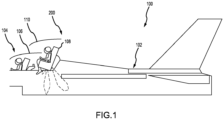
- an aircraft 100 may include a fuselage 102.
- the fuselage 102 may define or include a cockpit 104 in which one or more member of a flight crew may be located.
- the fuselage 102 may further define or include a second cockpit 108 in which one or more members of a flight crew may be located.
- the cockpit 104 may include one or more ejection systems to facilitate ejection of one or more members of the flight crew.
- the first cockpit 104 may include a hatch or canopy 106 that separates from or moves relative to the first cockpit 104 to allow the member or members of the flight crew in the first cockpit 104 to eject from the fuselage 102.
- the second cockpit 108 may further include a hatch or canopy 110 that separates from or moves relative to the second cockpit 108 to allow the member or members of the flight crew in the second cockpit 108 to eject from the fuselage 102.
- the aircraft 100 may be of any appropriate type and/or configuration (e.g., a passenger aircraft, a cargo aircraft, etc.).
- an exemplary ejection system 200 may be included in the cockpit 104.
- the ejection system 200 may include a seat 204 on which a user 202 may sit or otherwise rest and a helmet 206 which may be supported on a head of the user 202.
- the seat 204 may include various components of the ejection system 200 such as a main parachute 208 and a drogue 210.
- the seat 204 may further include a catapult or rocket that ejects the seat 204 and any occupant thereof from the cockpit 104.
- the drogue 210 may be a parachute that initially deploys after ejection of the seat 204 and may reduce a velocity of the seat 204 as it travels towards a ground surface.
- the main parachute 208 may deploy after the drogue 210 and may provide further reduction of the velocity of at least one of the seat 204 or the user 202 as it travels towards the ground surface.
- the ejection system 200 comprises an auditory ejection initiation system 300.
- the auditory ejection initiation system 300 is configured to initiate an ejection sequence of the ejection system 200 in response to detecting or receiving a predetermined word or phrase (i.e., a predetermined ejection command) used in the cockpit 104 as described further herein.
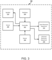
- the system 300 includes a controller 302 and a sensor 306.
- the controller 302 may include one or more logic devices such as one or more of a central processing unit (CPU), an accelerated processing unit (APU), a digital signal processor (DSP), a field programmable gate array (FPGA), an application specific integrated circuit (ASIC), or the like.
- the controller 302 may further include any non-transitory memory known in the art.
- the memory may store instructions usable by the logic device to perform operations.
- the senor 306 may include any sensor configured to convert sound waves into electrical energy variations which may then be amplified, transmitted, or recorded.
- the sensor 306 may comprise a condenser microphone, a dynamic microphone, a carbon microphone, a piezoelectric microphone, a fiber optic microphone, a laser microphone, a liquid microphone, a MicroElectrical-Mechanical System (MEMS) microphone, a speaker, a radio or any other device capable of wireless or wired transmissions.
- the sensor 306 is a component of a communication system 222.
- the sensor 306 may be disposed in any component of the communication system 222 (e.g., a headset, a radio, a transmitter, or the like).
- the communication system 222 may comprise a communication connector 224, which may be coupled between a component of the communication system 222 (e.g., a headset, a radio, a transmitter, or the like) and a connector 226 coupled to the seat 204 or another portion of the cockpit 104.
- the communication connector 224 may be removably coupled to both of the components of the communication system 222 and the connector 226 such that the user 202 may carry the communication connector 224 with him/her between aircraft.
- the communication connector 224 may contain ejection specific information for a respective pilot. For example, pilots may have their own predetermined ejection initiation phrase or command, which the respective pilot may carry between aircraft.
- a component of the communication system 222 may be removably coupled to the aircraft (and the communication connector 224 permanently or removably coupled to the component of the communication system 222) such that the user may carry the component of the communication system 222 (with the communication connector 224) with him/her between aircraft.
- the system 300 may further comprise a second sensor 308 configured to monitor physiological data of user 202 during operation of aircraft 100 from FIG. 1 .
- the second sensor 308 may be disposed in helmet 206.
- the second sensor 308 may be disposed anywhere in cockpit 104 where monitoring physiological data of user 202 may be performed.
- second sensor 308 may be integrated into a body suit of a user 202, shoes of a user 202, on a wrist device (e.g., a watch) of a user 202, or the like.
- physiological data may include at least one of a heart rate, brain activity, blood oxygen level, or any other physiological data used to detect abnormal physiological conditions of a user.
- the system 300 includes the controller 302, a database 304, and the sensor 306.
- the database 304 (or remote memory) may be located on a same aircraft as the system 300 or may be located remote from the aircraft.
- the controller 302 may communicate with the database 304 via any wired or wireless protocol. In that regard, the controller 302 may access data stored in the database 304.
- the database 304 may store pre-determined initiation words or phrases associated with auditory ejection initiation system 300 and may store specific settings for various components of the ejection system 200.
- an auditory ejection initiation system 300 may comprise a single auditory sensor (e.g., first sensor 306) and still be within the scope of this disclosure.
- the second sensor 308 may be configured to provide physiological data to the controller 302.
- the controller 302 may compare typical physiological conditions of a user (e.g., user 202) to the received physiological data and send a command to a speaker (e.g., located in a headset or elsewhere in cockpit 104 from FIGs 2A-B ) to ask the user 202 whether the user 202 wants to eject, in accordance with various embodiments.
- the second sensor 308 may facilitate detection of abnormal physiological conditions of a user (e.g., user 202 from FIGs. 2A-B ), which may be used as an input to controller 302 to prompt the user 202 whether or not to initiate ejection system 200 from FIGs. 2A-B through a speaker 310.
- a user e.g., user 202 from FIGs. 2A-B
- the system e.g., system 300
- the seat ejection initiation in response to an incoherent user may be time based (e.g., the speaker 310 may ask a user multiple times and initiate ejection if no response received within 10 seconds).
- the system 300 may include a mechanical override in the event of equipment malfunction (e.g., in an event sensor 306 is broken).
- a number of seats in aircraft 100 may be directly correlated to a number of sensors 306, 308 and speaker 310.
- two seats as illustrated in FIG. 1 , may include two sensors 306, two sensors 308, and two speakers 310 (i.e., one for each seat).
- a single seat aircraft may include one sensor 306, one sensor 308, and/or one speaker 310.
- each sensor 306, 308, and 310 could include multiple sensors in the same cockpit.
- EG forward cockpit could have multiple sensors 306, multiple sensors 308, and multiple speakers 310.
- a dual pilot aircraft e.g., aircraft 100 from FIG.
- the auditory ejection initiation system 300 may further comprise a seat electronic sequencer 324 and/or an inter-seat electronic sequencer 338.
- Each of the seat electronic sequencer 324 and/or the inter-seat electronic sequencer 338 may include one or more logic devices such as one or more of a central processing unit (CPU), an accelerated processing unit (APU), a digital signal processor (DSP), a field programmable gate array (FPGA), an application specific integrated circuit (ASIC), or the like. In various embodiments, these elements may further include any non-transitory memory known in the art.
- the seat electronic sequencer 324 and/or the inter-seat electronic sequencer 338 may be coupled to the controller 302 and may receive the specific settings from the controller 302 or may receive instructions regarding adjustments of components of the ejection system 200 from the controller 302.
- the interseat electronic sequencer 328 may make adjustments to components of the ejection system 200 that alter a sequence or timing of ejection events such as settings associated with an ejection order based on which cockpit (e.g., cockpit 104 or cockpit 108 from FIG. 1 ) initiates the ejection.
- the seat electronic sequencer 324 may set only the second ejection seat in cockpit 108 to eject from aircraft 100 when initiated by a non-pilot, in accordance with various embodiments.
- the interseat electronic sequencer 328 may set both the first ejection seat in cockpit 104 and the second ejection seat in cockpit 108 to eject when in a dual pilot mode, in accordance with various embodiments.
- the interseat electronic sequencer 328 may set only the first ejection seat in cockpit 104 to eject in a single pilot mode.
- the controller 302 may send a command to the interseat electronic sequencer 328 based on receiving an auditory ejection initiation from a respective sensor 306 of a first pilot, a second pilot, or a non-pilot as described further herein.
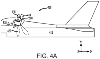
- Auditory ejection initiation system 500 may be installed in aircraft 412 to expel an ejection seat 414 and a pilot 416 of ejection seat 414 from a cockpit 418 of aircraft 412. Ejection seat 414 may be expelled from cockpit 418 by a propulsion system 420.
- Ejection seat 414 is illustrated prior to ejection initiation, in accordance with various embodiments.
- Ejection seat 414 includes a seat back 422 and a seat pan 424.
- a rocket catapult assembly 426 is coupled to seat back 422.
- an ejection handle 450 may be located proximate a front 428 of seat pan 424.
- Front 428 of seat pan 424 is generally opposite, or distal, seat back 422.
- FIG. 4B shows ejection handle 450 located at front 428 of seat pan 424, it is further contemplated and understood that ejection handle 450 may be located anywhere that is accessible to an occupant of ejection seat 414.
- ejection handle 450 may be located on a side 432 of seat pan 424 or a headrest 434 of seat back 422.
- both cockpits e.g., cockpit 104 and cockpit 108 from a dual pilot aircraft (e.g., aircraft 100 from FIG. 1 ) may include an ejection handle 450, in accordance with FIG. 4B .
- both cockpits e.g., cockpit 104 and cockpit 108 from a dual pilot aircraft (e.g., aircraft 100 from FIG. 1 ) may be configured for manual ejection, as well as auditory ejection.
- the present disclosure is not limited in this regard.
- aircrafts 100, 400 may be configured for sensor-based ejection only (e.g., based on auditory data, physiological data, etc.) or dual ejection initiation methods (e.g., via ejection handle 450 or auditory ejection as described further herein.
- a pilot 416 may manually initiate an ejection sequence by pulling the ejection handle 450 in a vertical direction in accordance with arrow 460.
- FIG. 5 an auditory ejection initiation system 500 for use in aircraft 400 is illustrated, in accordance with various embodiments. Although described herein as being used in a single pilot aircraft (e.g., aircraft 400), auditory ejection initiation system 500 may also be utilized in dual pilot aircraft (e.g., aircraft 100 from FIG. 1 ) and be within the scope of this disclosure.
- the auditory ejection initiation system 500 includes the controller 302, the database 304, the sensors 306, 308, and the speaker 310 of auditory ejection initiation system 300.
- the auditory ejection initiation system 500 further comprises an ejection device 502 (e.g., a mechanical device, a ballistic device, etc.).
- the ejection device 502 is configured to receive an electronic signal to from controller 302 initiate the ejection device.
- ejection device 502 may actuate ejection device 502 and initiate an ejection event, as described further herein.
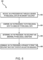
- the method 600 comprises receiving, via a processor (e.g., controller 302 from FIGs. 3 , 5 ) and through a sensor (e.g., sensor 308 from FIGs. 3 , 5 ), physiological data of an aircraft occupant (e.g., user 202 from FIGs. 2A-B or pilot 416 from FIGs. 4A-B ) (step 602).
- a processor e.g., controller 302 from FIGs. 3 , 5
- a sensor e.g., sensor 308 from FIGs. 3 , 5
- physiological data of an aircraft occupant e.g., user 202 from FIGs. 2A-B or pilot 416 from FIGs. 4A-B
- the method 600 further comprises comparing, via the processor, the physiological data to a baseline physiological data (step 604).
- the baseline physiological data may be stored in a database (e.g., database 304) or remote memory of an auditory ejection initiation system (e.g., system 300 or system 500).
- the baseline physiological data may correspond directly to the user (e.g., uploaded in response to the user connecting connector 224 to the system 300), or may be a baseline physiological data for typical pilots, or a specific pilot.
- the method 600 further comprises determining, via the processor, the occupant has abnormal physiological conditions (e.g., low heartrate, low brain activity, high pulse, low oxygen levels, etc.) (step 606).
- the processor may determine that the pilot is unconscious, or near unconscious.
- the processor in response to determining the occupant has abnormal physiological conditions, may command a speaker to prompt the occupant whether to initiate an ejection sequence (step 608).
- an ejection event in response to determining the occupant has abnormal physiological conditions over an extended period of time (e.g., a predetermined threshold), an ejection event may be initiated automatically.
- method 700 may occur in succession with method 600 from FIG. 6 .
- the user may initiate auditory ejection via method 700, in accordance with various embodiments.
- the method 700 comprises receiving, via a processor (e.g., controller 302 from FIG. 3 ) and through a sensor (e.g., sensor 306 from FIG. 3 ), an ejection command from an aircraft occupant (e.g., user 202 from FIGs. 2A-B ) (step 702).
- the ejection command is a single word or a phrase.
- the ejection command is multiple words.
- the ejection command is a single word repeated multiple times.
- the ejection command may comprise saying eject three times (e.g., "EJECT, EJECT, EJECT").
- accidental ejection may be prevented. For example, if a single word is used, an occupant may accidently say the single word while communicating with other pilots.
- the method 700 further comprises comparing, via the processor, the ejection command to a predetermined ejection command (step 704).
- the predetermined ejection command is stored in a database (e.g., database 304).
- the ejection command may be specific to a user (e.g., uploaded to the system 300 via connector 224) or uniform across aircrafts.
- the method 700 further comprises determining, via the processor, the ejection command matches the predetermined ejection command (step 706) and commanding, via the processor and through a seat electronic sequencer (e.g., seat electronic sequencer 324 from FIG. 3 ) to initiate an ejection event (step 708).
- the command of step 708 may include an ejection sequence based on which sensor the processor received the ejection command from in step 702. For example, in a dual pilot mode or a pilot/non-pilot mode, if the ejection command is received from a sensor corresponding to a pilot in a first cockpit (e.g., cockpit 104 from FIG.
- the ejection event may eject both occupants (i.e., the aft occupant first, followed by the pilot in the first cockpit), in accordance with various embodiments.
- a pilot / non-pilot mode if the ejection command is received from a sensor corresponding to the non-pilot, only the non-pilot may be ejected from the aircraft, in accordance with various embodiments.
- a single pilot mode only the ejection seat corresponding to the single pilot may be ejected, in accordance with various embodiments.
- whether an occupant is a pilot, or a non-pilot may be determined by connecting connector 224 to system 300 from FIGs. 2A-B .
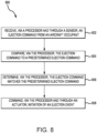
- method 800 may occur in succession with method 600 from FIG. 6 .
- the user may initiate auditory ejection via method 800, in accordance with various embodiments.
- the method 800 comprises receiving, via a processor (e.g., controller 302 from FIG. 5 ) and through a sensor (e.g., sensor 306 from FIG. 3 ), an ejection command from an aircraft occupant (e.g., user 202 from FIGs. 2A-B ) (step 702).
- the ejection command is a single word or a command.
- the ejection command is multiple words.
- the ejection command is a single word repeated multiple times.
- the ejection command may comprise saying eject three times (e.g., "EJECT, EJECT, EJECT").
- accidental ejection may be prevented. For example, if a single word is used, an occupant may accidently say the single word while communicating with other pilots.
- the method 800 further comprises comparing, via the processor, the ejection command to a predetermined ejection command (step 804).
- the predetermined ejection command is stored in a database (e.g., database 304).
- the ejection command may be specific to a user (e.g., uploaded to the system 500 via connector 224 from FIG. 2B ) or uniform across aircrafts.
- the method 800 further comprises determining, via the processor, the ejection command matches the predetermined ejection command (step 806) and commanding, via the processor and through an ejection device (e.g., ejection device 502 from FIG. 5 ) to initiate an ejection event (step 808).
- the ejection device may be a mechanical device, a ballistic device, or the like. In this regard, in response to receiving an electrical signal from the processor, the ejection device may actuate, causing an ejection event to initiate.
- the auditory ejection initiation systems 300, 500 and aircraft ejection initiation methods 600, 700, 800 disclosed herein may add redundancy to an ejection initiation system.
- the auditory ejection initiation systems 300, 500 and aircraft ejection initiation methods 600, 700, 800 disclosed herein may provide an additional method to eject an incapacitated or injured pilot.
- the auditory ejection initiation systems 300, 500 and aircraft ejection initiation methods 600, 700, 800 may allow a pilot to position his or her arms for optimal protection in preparation of an ejection event.
- references to “various embodiments”, “one embodiment”, “an embodiment”, “an example embodiment”, etc., indicate that the embodiment described may include a particular feature, structure, or characteristic, but every embodiment may not necessarily include the particular feature, structure, or characteristic.
Landscapes
- Engineering & Computer Science (AREA)
- Aviation & Aerospace Engineering (AREA)
- Business, Economics & Management (AREA)
- Emergency Management (AREA)
- Automation & Control Theory (AREA)
- Alarm Systems (AREA)
- Emergency Alarm Devices (AREA)
Claims (11)
- Verfahren zum akustischen Auswurf eines Luftfahrzeuginsassen aus einem Luftfahrzeug, wobei das Verfahren folgendes umfasst:Empfangen, über einen Prozessor (302) und durch einen akustischen Sensor (306),einen Auswurfbefehl der Insassen des Luftfahrzeugs;Vergleichen des Auswurfbefehls über den Prozessor mit einem vorbestimmten Auswurfbefehl, der in einer Datenbank gespeichert ist;Bestimmen, über den Prozessor, ob der Auswurfbefehl mit dem vorbestimmten Auswurfbefehl übereinstimmt; undBefehlen, über den Prozessor, der Einleitung eines Auswurfereignisses als Reaktion auf den Auswurfbefehl, der mit dem vorbestimmten Auswurfbefehl übereinstimmt, dadurch gekennzeichnet, dass der vorbestimmte Auswurfbefehl ein Wort, eine Reihe von Wörtern, ein einzelnes Wort oder ein mehrfach wiederholtes Wort beinhaltet.
- Verfahren nach Anspruch 1, wobei das Befehlen der Auslösung des Auswurfereignisses das Senden eines elektrischen Signals an eine Auswurfvorrichtung (502) über den Prozessor beinhaltet, und optional,
wobei die Auswurfvorrichtung die Auswurfvorrichtung in Reaktion auf den Empfang des elektrischen Signals betätigt. - Verfahren nach Anspruch 1 oder 2, ferner umfassend das Bestimmen einer Auswurfsequenz basierend auf einem Standort des akustischen Sensors (306)
in dem Luftfahrzeug oder bei dem Luftfahrzeuginsassen, der sich entweder in einem ersten Cockpit (104) oder in einem zweiten Cockpit (108) des Luftfahrzeugs oder bei dem Luftfahrzeuginsassen befindet, und optional ferner umfassend das Bestimmen, dass sich ein Nicht-Pilot in dem zweiten Cockpit befindet. - Verfahren nach Anspruch 3, wobei ein zweiter Auswurfsitz im zweiten Cockpit als Reaktion darauf, dass sich der Sensor im zweiten Cockpit befindet, ausgeworfen wird.
- Verfahren nach einem der vorhergehenden Ansprüche, wobei der akustische Sensor ein Mikrofon ist.
- Verfahren nach einem der vorhergehenden Ansprüche, ferner umfassend:Empfangen von physiologischen Daten eines Insassen eines Luftfahrzeugs über den Prozessor (302) und durch einen zweiten Sensor (308); undBefehlen eines Lautsprechers (310) über den Prozessor, den Insassen des Luftfahrzeugs aufzufordern, als Reaktion darauf, dass der Insasse des Luftfahrzeugs einen abnormalen physiologischen Zustand aufweist, der auf den physiologischen Daten basiert.
- Verfahren nach Anspruch 6, ferner umfassend:Vergleichen der physiologischen Daten über den Prozessor mit den physiologischen Basisdaten; undBestimmen des Insassen des Luftfahrzeugs, der den abnormalen physiologischen Zustand aufweist, über den Prozessor.
- System zum Auslösen eines akustischen Auswurfs aus einem Luftfahrzeug, wobei das System folgendes umfasst:einen akustischen Sensor (306);einen Auswurfsitz (204), der so konfiguriert ist, dass er als Reaktion auf die Auslösung eines Auswurfereignisses aus dem Luftfahrzeug ausgeworfen wird; undeine Steuerung (302) in betriebsfähiger Kommunikation mit dem akustischen Sensor, wobei die Steuerung konfiguriert ist zum:Empfangen eines Auswurfbefehls von einem Insassen eines Luftfahrzeugs über den akustischen Sensor; undBefehlen der Einleitung des Auswurfvorgangs als Reaktion darauf, dass der Auswurfbefehl mit einem vorbestimmten Auswurfbefehl übereinstimmt, der in einer Datenbank gespeichert ist, dadurch gekennzeichnet, dass der vorbestimmte Auswurfbefehl eines von einem Wort, einer Reihe von Wörtern, einem einzelnen Wort oder einem mehrfach wiederholten Wort beinhaltet.
- System nach Anspruch 8, ferner umfassend einen zweiten Sensor (308) in betriebsfähiger Verbindung mit dem Auswurfsitz, wobei der zweite Sensor so konfiguriert ist, dass er physiologische Daten von dem Insassen des Luftfahrzeugs erkennt, und optional
wobei die Steuerung ferner konfiguriert ist zum:Empfangen der physiologischen Daten über den zweiten Sensor;Vergleichen der physiologischen Ausgangsbedingungen der Insassen des Luftfahrzeugs mit den physiologischen Daten;Bestimmen, dass der Insasse des Luftfahrzeugs mindestens einen abnormalen physiologischen Zustand aufweist, basierend auf dem Vergleich; undAuslösen des Schleudersitzes als Reaktion auf das Bestimmen, dass der Insasse des Luftfahrzeugs mindestens einen abnormalen physiologischen Zustand aufweist. - System nach Anspruch 8 oder 9, ferner umfassend einen Auswurfgriff (450), wobei der Auswurfgriff so konfiguriert ist, dass er den Auswurfvorgang manuell auslöst, und optional ferner umfassend eine Auswurfvorrichtung (502), wobei die Befehlsauslösung des Auswurfereignisses ferner das Senden eines elektrischen Signals an die Auswurfvorrichtung umfasst.
- System nach Anspruch 10, wobei die Steuerung ferner so konfiguriert sein kann, dass sie einem Lautsprecher (310) befiehlt, den Insassen des Luftfahrzeugs zu fragen, ob er den Schleudervorgang einleiten soll.
Applications Claiming Priority (1)
| Application Number | Priority Date | Filing Date | Title |
|---|---|---|---|
| US17/231,798 US11565791B2 (en) | 2021-04-15 | 2021-04-15 | Sensor-based ejection initiation system |
Publications (2)
| Publication Number | Publication Date |
|---|---|
| EP4074604A1 EP4074604A1 (de) | 2022-10-19 |
| EP4074604B1 true EP4074604B1 (de) | 2024-07-24 |
Family
ID=81384902
Family Applications (1)
| Application Number | Title | Priority Date | Filing Date |
|---|---|---|---|
| EP22167001.1A Active EP4074604B1 (de) | 2021-04-15 | 2022-04-06 | Sensorbasiertes auswurfauslösesystem |
Country Status (2)
| Country | Link |
|---|---|
| US (1) | US11565791B2 (de) |
| EP (1) | EP4074604B1 (de) |
Families Citing this family (2)
| Publication number | Priority date | Publication date | Assignee | Title |
|---|---|---|---|---|
| US11891183B2 (en) * | 2020-09-29 | 2024-02-06 | Ami Industries, Inc. | Automatic ejection seat performance and accomodation optimization based on active input of aircrew data |
| US20250388334A1 (en) * | 2024-06-21 | 2025-12-25 | Rockwell Collins, Inc. | Multi-polynomial variable modes with event inversion, event inhibit, and event delay scaling |
Family Cites Families (5)
| Publication number | Priority date | Publication date | Assignee | Title |
|---|---|---|---|---|
| US4721273A (en) * | 1986-08-08 | 1988-01-26 | The Boeing Company | Life-threat assessment and control command for aircrew escape systems |
| US5894285A (en) | 1997-08-29 | 1999-04-13 | Motorola, Inc. | Method and apparatus to sense aircraft pilot ejection for rescue radio actuation |
| US10399686B2 (en) * | 2016-02-12 | 2019-09-03 | Cirrus Design Corporation | Mechanical timing connection for sequencing airbag activation with rocket for deploying aircraft parachute |
| US10752360B2 (en) | 2017-12-05 | 2020-08-25 | Textron Innovations Inc. | Aircraft restraint systems with fixed default mode |
| US11518527B2 (en) | 2020-09-29 | 2022-12-06 | Ami Industries, Inc. | Automatic ejection seat performance optimization based on detection of aircrew weight |
-
2021
- 2021-04-15 US US17/231,798 patent/US11565791B2/en active Active
-
2022
- 2022-04-06 EP EP22167001.1A patent/EP4074604B1/de active Active
Also Published As
| Publication number | Publication date |
|---|---|
| EP4074604A1 (de) | 2022-10-19 |
| US11565791B2 (en) | 2023-01-31 |
| US20220332407A1 (en) | 2022-10-20 |
Similar Documents
| Publication | Publication Date | Title |
|---|---|---|
| US11993386B2 (en) | Smart systems and methods for automatic deployment of an ejection system | |
| EP4074604A1 (de) | Sensorbasiertes auswurfauslösesystem | |
| US8200379B2 (en) | Smart recovery system | |
| US10118707B2 (en) | Aircraft parachute deployment autopilot | |
| EP3974319B1 (de) | Automatische optimierung der leistung eines schleudersitzes basierend auf der erfassung des gewichts der flugzeugbesatzung | |
| US11427339B2 (en) | Passive head and neck protection canopy piercer | |
| EP3974321B1 (de) | Optimierung der leistung und unterbringung eines automatischen schleudersitzes auf basis der aktiven eingabe von flugbesatzungsdaten | |
| US11597521B2 (en) | Aircraft restraint systems with unfixed default mode | |
| US20210323684A1 (en) | Automatic ejection time delay system | |
| JP2003054498A (ja) | 超音速搬送装置 | |
| EP4140894B1 (de) | Rückhaltesysteme und verfahren für schleudersitze | |
| EP3974320B1 (de) | Automatische schleudersitzleistungs- und -aufnahmeoptimierung auf basis eines verbinders | |
| EP3738881B1 (de) | Universeller sequenzer und kabelbaumanordnung für ausstosssysteme | |
| US12208720B2 (en) | Vibrotactile systems and methods for aircraft seats | |
| EP3075659B1 (de) | Schleudersitzstabilisierungsbremsschirm zur apogäumsverbesserung | |
| US6296204B1 (en) | Restraint system for a flight helmet | |
| US20160046378A1 (en) | Restraint for side facing seats installed in an aircraft | |
| KR101889804B1 (ko) | 백업용 자동좌석사출장치 | |
| CN114261526A (zh) | 一种基于机体交互信号的避免飞行员误弹射的告警系统 | |
| RU2661203C1 (ru) | Спасательно-десантное устройство вертолетного типа с электроприводом | |
| RU186459U1 (ru) | 1 безопасный самолёт фокина | |
| RU2672220C1 (ru) | Система спасения пассажиров и экипажа летательного аппарата при его разрушении | |
| US11873108B2 (en) | Drogue to seat separation assembly having pyrotechnic fastener | |
| MACANDER | REASONS FOR FAILED EJECTIONS IN THE POLISH AIR FORCE IN THE YEARS 1951-2021 | |
| US20240109661A1 (en) | Biometrically actuated occupant restraint system and method for a vehicle |
Legal Events
| Date | Code | Title | Description |
|---|---|---|---|
| PUAI | Public reference made under article 153(3) epc to a published international application that has entered the european phase |
Free format text: ORIGINAL CODE: 0009012 |
|
| STAA | Information on the status of an ep patent application or granted ep patent |
Free format text: STATUS: THE APPLICATION HAS BEEN PUBLISHED |
|
| AK | Designated contracting states |
Kind code of ref document: A1 Designated state(s): AL AT BE BG CH CY CZ DE DK EE ES FI FR GB GR HR HU IE IS IT LI LT LU LV MC MK MT NL NO PL PT RO RS SE SI SK SM TR |
|
| STAA | Information on the status of an ep patent application or granted ep patent |
Free format text: STATUS: REQUEST FOR EXAMINATION WAS MADE |
|
| 17P | Request for examination filed |
Effective date: 20230419 |
|
| RBV | Designated contracting states (corrected) |
Designated state(s): AL AT BE BG CH CY CZ DE DK EE ES FI FR GB GR HR HU IE IS IT LI LT LU LV MC MK MT NL NO PL PT RO RS SE SI SK SM TR |
|
| P01 | Opt-out of the competence of the unified patent court (upc) registered |
Effective date: 20230922 |
|
| GRAP | Despatch of communication of intention to grant a patent |
Free format text: ORIGINAL CODE: EPIDOSNIGR1 |
|
| STAA | Information on the status of an ep patent application or granted ep patent |
Free format text: STATUS: GRANT OF PATENT IS INTENDED |
|
| INTG | Intention to grant announced |
Effective date: 20240229 |
|
| GRAS | Grant fee paid |
Free format text: ORIGINAL CODE: EPIDOSNIGR3 |
|
| GRAA | (expected) grant |
Free format text: ORIGINAL CODE: 0009210 |
|
| STAA | Information on the status of an ep patent application or granted ep patent |
Free format text: STATUS: THE PATENT HAS BEEN GRANTED |
|
| AK | Designated contracting states |
Kind code of ref document: B1 Designated state(s): AL AT BE BG CH CY CZ DE DK EE ES FI FR GB GR HR HU IE IS IT LI LT LU LV MC MK MT NL NO PL PT RO RS SE SI SK SM TR |
|
| REG | Reference to a national code |
Ref country code: GB Ref legal event code: FG4D |
|
| REG | Reference to a national code |
Ref country code: CH Ref legal event code: EP |
|
| REG | Reference to a national code |
Ref country code: IE Ref legal event code: FG4D Ref country code: DE Ref legal event code: R096 Ref document number: 602022004715 Country of ref document: DE |
|
| REG | Reference to a national code |
Ref country code: LT Ref legal event code: MG9D |
|
| REG | Reference to a national code |
Ref country code: NL Ref legal event code: MP Effective date: 20240724 |
|
| PG25 | Lapsed in a contracting state [announced via postgrant information from national office to epo] |
Ref country code: PT Free format text: LAPSE BECAUSE OF FAILURE TO SUBMIT A TRANSLATION OF THE DESCRIPTION OR TO PAY THE FEE WITHIN THE PRESCRIBED TIME-LIMIT Effective date: 20241125 |
|
| REG | Reference to a national code |
Ref country code: AT Ref legal event code: MK05 Ref document number: 1706099 Country of ref document: AT Kind code of ref document: T Effective date: 20240724 |
|
| PG25 | Lapsed in a contracting state [announced via postgrant information from national office to epo] |
Ref country code: NL Free format text: LAPSE BECAUSE OF FAILURE TO SUBMIT A TRANSLATION OF THE DESCRIPTION OR TO PAY THE FEE WITHIN THE PRESCRIBED TIME-LIMIT Effective date: 20240724 |
|
| PG25 | Lapsed in a contracting state [announced via postgrant information from national office to epo] |
Ref country code: PT Free format text: LAPSE BECAUSE OF FAILURE TO SUBMIT A TRANSLATION OF THE DESCRIPTION OR TO PAY THE FEE WITHIN THE PRESCRIBED TIME-LIMIT Effective date: 20241125 Ref country code: NL Free format text: LAPSE BECAUSE OF FAILURE TO SUBMIT A TRANSLATION OF THE DESCRIPTION OR TO PAY THE FEE WITHIN THE PRESCRIBED TIME-LIMIT Effective date: 20240724 |
|
| PG25 | Lapsed in a contracting state [announced via postgrant information from national office to epo] |
Ref country code: NO Free format text: LAPSE BECAUSE OF FAILURE TO SUBMIT A TRANSLATION OF THE DESCRIPTION OR TO PAY THE FEE WITHIN THE PRESCRIBED TIME-LIMIT Effective date: 20241024 |
|
| PG25 | Lapsed in a contracting state [announced via postgrant information from national office to epo] |
Ref country code: PL Free format text: LAPSE BECAUSE OF FAILURE TO SUBMIT A TRANSLATION OF THE DESCRIPTION OR TO PAY THE FEE WITHIN THE PRESCRIBED TIME-LIMIT Effective date: 20240724 Ref country code: GR Free format text: LAPSE BECAUSE OF FAILURE TO SUBMIT A TRANSLATION OF THE DESCRIPTION OR TO PAY THE FEE WITHIN THE PRESCRIBED TIME-LIMIT Effective date: 20241025 Ref country code: FI Free format text: LAPSE BECAUSE OF FAILURE TO SUBMIT A TRANSLATION OF THE DESCRIPTION OR TO PAY THE FEE WITHIN THE PRESCRIBED TIME-LIMIT Effective date: 20240724 |
|
| PG25 | Lapsed in a contracting state [announced via postgrant information from national office to epo] |
Ref country code: BG Free format text: LAPSE BECAUSE OF FAILURE TO SUBMIT A TRANSLATION OF THE DESCRIPTION OR TO PAY THE FEE WITHIN THE PRESCRIBED TIME-LIMIT Effective date: 20240724 |
|
| PG25 | Lapsed in a contracting state [announced via postgrant information from national office to epo] |
Ref country code: LV Free format text: LAPSE BECAUSE OF FAILURE TO SUBMIT A TRANSLATION OF THE DESCRIPTION OR TO PAY THE FEE WITHIN THE PRESCRIBED TIME-LIMIT Effective date: 20240724 |
|
| PG25 | Lapsed in a contracting state [announced via postgrant information from national office to epo] |
Ref country code: IS Free format text: LAPSE BECAUSE OF FAILURE TO SUBMIT A TRANSLATION OF THE DESCRIPTION OR TO PAY THE FEE WITHIN THE PRESCRIBED TIME-LIMIT Effective date: 20241124 Ref country code: AT Free format text: LAPSE BECAUSE OF FAILURE TO SUBMIT A TRANSLATION OF THE DESCRIPTION OR TO PAY THE FEE WITHIN THE PRESCRIBED TIME-LIMIT Effective date: 20240724 |
|
| PG25 | Lapsed in a contracting state [announced via postgrant information from national office to epo] |
Ref country code: HR Free format text: LAPSE BECAUSE OF FAILURE TO SUBMIT A TRANSLATION OF THE DESCRIPTION OR TO PAY THE FEE WITHIN THE PRESCRIBED TIME-LIMIT Effective date: 20240724 |
|
| PG25 | Lapsed in a contracting state [announced via postgrant information from national office to epo] |
Ref country code: RS Free format text: LAPSE BECAUSE OF FAILURE TO SUBMIT A TRANSLATION OF THE DESCRIPTION OR TO PAY THE FEE WITHIN THE PRESCRIBED TIME-LIMIT Effective date: 20241024 Ref country code: ES Free format text: LAPSE BECAUSE OF FAILURE TO SUBMIT A TRANSLATION OF THE DESCRIPTION OR TO PAY THE FEE WITHIN THE PRESCRIBED TIME-LIMIT Effective date: 20240724 |
|
| PG25 | Lapsed in a contracting state [announced via postgrant information from national office to epo] |
Ref country code: RS Free format text: LAPSE BECAUSE OF FAILURE TO SUBMIT A TRANSLATION OF THE DESCRIPTION OR TO PAY THE FEE WITHIN THE PRESCRIBED TIME-LIMIT Effective date: 20241024 Ref country code: PL Free format text: LAPSE BECAUSE OF FAILURE TO SUBMIT A TRANSLATION OF THE DESCRIPTION OR TO PAY THE FEE WITHIN THE PRESCRIBED TIME-LIMIT Effective date: 20240724 Ref country code: NO Free format text: LAPSE BECAUSE OF FAILURE TO SUBMIT A TRANSLATION OF THE DESCRIPTION OR TO PAY THE FEE WITHIN THE PRESCRIBED TIME-LIMIT Effective date: 20241024 Ref country code: LV Free format text: LAPSE BECAUSE OF FAILURE TO SUBMIT A TRANSLATION OF THE DESCRIPTION OR TO PAY THE FEE WITHIN THE PRESCRIBED TIME-LIMIT Effective date: 20240724 Ref country code: IS Free format text: LAPSE BECAUSE OF FAILURE TO SUBMIT A TRANSLATION OF THE DESCRIPTION OR TO PAY THE FEE WITHIN THE PRESCRIBED TIME-LIMIT Effective date: 20241124 Ref country code: HR Free format text: LAPSE BECAUSE OF FAILURE TO SUBMIT A TRANSLATION OF THE DESCRIPTION OR TO PAY THE FEE WITHIN THE PRESCRIBED TIME-LIMIT Effective date: 20240724 Ref country code: GR Free format text: LAPSE BECAUSE OF FAILURE TO SUBMIT A TRANSLATION OF THE DESCRIPTION OR TO PAY THE FEE WITHIN THE PRESCRIBED TIME-LIMIT Effective date: 20241025 Ref country code: FI Free format text: LAPSE BECAUSE OF FAILURE TO SUBMIT A TRANSLATION OF THE DESCRIPTION OR TO PAY THE FEE WITHIN THE PRESCRIBED TIME-LIMIT Effective date: 20240724 Ref country code: ES Free format text: LAPSE BECAUSE OF FAILURE TO SUBMIT A TRANSLATION OF THE DESCRIPTION OR TO PAY THE FEE WITHIN THE PRESCRIBED TIME-LIMIT Effective date: 20240724 Ref country code: BG Free format text: LAPSE BECAUSE OF FAILURE TO SUBMIT A TRANSLATION OF THE DESCRIPTION OR TO PAY THE FEE WITHIN THE PRESCRIBED TIME-LIMIT Effective date: 20240724 Ref country code: AT Free format text: LAPSE BECAUSE OF FAILURE TO SUBMIT A TRANSLATION OF THE DESCRIPTION OR TO PAY THE FEE WITHIN THE PRESCRIBED TIME-LIMIT Effective date: 20240724 |
|
| PG25 | Lapsed in a contracting state [announced via postgrant information from national office to epo] |
Ref country code: DK Free format text: LAPSE BECAUSE OF FAILURE TO SUBMIT A TRANSLATION OF THE DESCRIPTION OR TO PAY THE FEE WITHIN THE PRESCRIBED TIME-LIMIT Effective date: 20240724 Ref country code: RO Free format text: LAPSE BECAUSE OF FAILURE TO SUBMIT A TRANSLATION OF THE DESCRIPTION OR TO PAY THE FEE WITHIN THE PRESCRIBED TIME-LIMIT Effective date: 20240724 Ref country code: SM Free format text: LAPSE BECAUSE OF FAILURE TO SUBMIT A TRANSLATION OF THE DESCRIPTION OR TO PAY THE FEE WITHIN THE PRESCRIBED TIME-LIMIT Effective date: 20240724 |
|
| PG25 | Lapsed in a contracting state [announced via postgrant information from national office to epo] |
Ref country code: EE Free format text: LAPSE BECAUSE OF FAILURE TO SUBMIT A TRANSLATION OF THE DESCRIPTION OR TO PAY THE FEE WITHIN THE PRESCRIBED TIME-LIMIT Effective date: 20240724 |
|
| PG25 | Lapsed in a contracting state [announced via postgrant information from national office to epo] |
Ref country code: CZ Free format text: LAPSE BECAUSE OF FAILURE TO SUBMIT A TRANSLATION OF THE DESCRIPTION OR TO PAY THE FEE WITHIN THE PRESCRIBED TIME-LIMIT Effective date: 20240724 |
|
| REG | Reference to a national code |
Ref country code: DE Ref legal event code: R097 Ref document number: 602022004715 Country of ref document: DE |
|
| PG25 | Lapsed in a contracting state [announced via postgrant information from national office to epo] |
Ref country code: SK Free format text: LAPSE BECAUSE OF FAILURE TO SUBMIT A TRANSLATION OF THE DESCRIPTION OR TO PAY THE FEE WITHIN THE PRESCRIBED TIME-LIMIT Effective date: 20240724 Ref country code: IT Free format text: LAPSE BECAUSE OF FAILURE TO SUBMIT A TRANSLATION OF THE DESCRIPTION OR TO PAY THE FEE WITHIN THE PRESCRIBED TIME-LIMIT Effective date: 20240724 |
|
| PLBE | No opposition filed within time limit |
Free format text: ORIGINAL CODE: 0009261 |
|
| STAA | Information on the status of an ep patent application or granted ep patent |
Free format text: STATUS: NO OPPOSITION FILED WITHIN TIME LIMIT |
|
| 26N | No opposition filed |
Effective date: 20250425 |
|
| PGFP | Annual fee paid to national office [announced via postgrant information from national office to epo] |
Ref country code: DE Payment date: 20250319 Year of fee payment: 4 |
|
| PG25 | Lapsed in a contracting state [announced via postgrant information from national office to epo] |
Ref country code: SE Free format text: LAPSE BECAUSE OF FAILURE TO SUBMIT A TRANSLATION OF THE DESCRIPTION OR TO PAY THE FEE WITHIN THE PRESCRIBED TIME-LIMIT Effective date: 20240724 |
|
| REG | Reference to a national code |
Ref country code: CH Ref legal event code: H13 Free format text: ST27 STATUS EVENT CODE: U-0-0-H10-H13 (AS PROVIDED BY THE NATIONAL OFFICE) Effective date: 20251125 |
|
| PG25 | Lapsed in a contracting state [announced via postgrant information from national office to epo] |
Ref country code: LU Free format text: LAPSE BECAUSE OF NON-PAYMENT OF DUE FEES Effective date: 20250406 |
|
| PG25 | Lapsed in a contracting state [announced via postgrant information from national office to epo] |
Ref country code: MC Free format text: LAPSE BECAUSE OF FAILURE TO SUBMIT A TRANSLATION OF THE DESCRIPTION OR TO PAY THE FEE WITHIN THE PRESCRIBED TIME-LIMIT Effective date: 20240724 |
|
| REG | Reference to a national code |
Ref country code: BE Ref legal event code: MM Effective date: 20250430 |
|
| PG25 | Lapsed in a contracting state [announced via postgrant information from national office to epo] |
Ref country code: BE Free format text: LAPSE BECAUSE OF NON-PAYMENT OF DUE FEES Effective date: 20250430 |
|
| PG25 | Lapsed in a contracting state [announced via postgrant information from national office to epo] |
Ref country code: CH Free format text: LAPSE BECAUSE OF NON-PAYMENT OF DUE FEES Effective date: 20250430 |
|
| PGFP | Annual fee paid to national office [announced via postgrant information from national office to epo] |
Ref country code: GB Payment date: 20260319 Year of fee payment: 5 |
|
| PG25 | Lapsed in a contracting state [announced via postgrant information from national office to epo] |
Ref country code: IE Free format text: LAPSE BECAUSE OF NON-PAYMENT OF DUE FEES Effective date: 20250406 |
|
| PGFP | Annual fee paid to national office [announced via postgrant information from national office to epo] |
Ref country code: FR Payment date: 20260320 Year of fee payment: 5 |