EP4140894B1 - Rückhaltesysteme und verfahren für schleudersitze - Google Patents
Rückhaltesysteme und verfahren für schleudersitze Download PDFInfo
- Publication number
- EP4140894B1 EP4140894B1 EP22187321.9A EP22187321A EP4140894B1 EP 4140894 B1 EP4140894 B1 EP 4140894B1 EP 22187321 A EP22187321 A EP 22187321A EP 4140894 B1 EP4140894 B1 EP 4140894B1
- Authority
- EP
- European Patent Office
- Prior art keywords
- ejection
- cord
- retraction mechanism
- cuff assembly
- seat
- Prior art date
- Legal status (The legal status is an assumption and is not a legal conclusion. Google has not performed a legal analysis and makes no representation as to the accuracy of the status listed.)
- Active
Links
Images




Classifications
-
- B—PERFORMING OPERATIONS; TRANSPORTING
- B64—AIRCRAFT; AVIATION; COSMONAUTICS
- B64D—EQUIPMENT FOR FITTING IN OR TO AIRCRAFT; FLIGHT SUITS; PARACHUTES; ARRANGEMENT OR MOUNTING OF POWER PLANTS OR PROPULSION TRANSMISSIONS IN AIRCRAFT
- B64D25/00—Emergency apparatus or devices, not otherwise provided for
- B64D25/08—Ejecting or escaping means
- B64D25/10—Ejector seats
-
- B—PERFORMING OPERATIONS; TRANSPORTING
- B64—AIRCRAFT; AVIATION; COSMONAUTICS
- B64D—EQUIPMENT FOR FITTING IN OR TO AIRCRAFT; FLIGHT SUITS; PARACHUTES; ARRANGEMENT OR MOUNTING OF POWER PLANTS OR PROPULSION TRANSMISSIONS IN AIRCRAFT
- B64D25/00—Emergency apparatus or devices, not otherwise provided for
- B64D25/02—Supports or holding means for living bodies
- B64D25/06—Harnessing
Definitions
- the present disclosure relates to aircraft ejection seats, and more specifically, to retention systems and methods for aircraft ejection seats.
- Ejection systems are designed to expel pilots from an aircraft cockpit.
- Ejection seats in high performance aircraft benefit from safely removing the pilot or other occupant from the disabled aircraft across a wide variety of aircraft speed regimes, altitudes and aircraft attitudes.
- Ejection seats may experience a high velocity windblast due to ejection seats entering a wind stream during an ejection event. Arms of occupants may be susceptible to being exposed to the high velocity wind blast during the ejection event.
- GB 1 456 007 A describes improvement in or relating to restraining means in vehicle ejection seats.
- US 4 247 064 A describes a limb retention system.
- US 3 424 408 A describes a vehicle ejection seat.
- US 2 940 701 A describes personnel escape equipment.
- US 3 957 231 A describes s restraint system.
- An evacuation system for an aircraft ejection system is disclosed herein and defined in claim 1.
- the controller is in operable communication with the retraction mechanism, the controller further configured to command the retraction mechanism to retract the cord in response to the ejection event being initiated.
- the controller may be further configured to command the retraction mechanism to lock the cord in response to the ejection event being initiated.
- the cuff assembly may be disposed between being flush with a seat back and being a foot (35 cm) from the seat back in response to the retraction mechanism locking.
- the system may further comprise a second cuff assembly coupled to the cord.
- the system may comprise: a first cuff assembly disposed on a first side of an ejection seat; a second cuff assembly disposed on a second side of the ejection seat; a first cord extending from within the ejection seat to the first cuff assembly; a second cord extending from within the ejection seat to the second cuff assembly, the system configured to allow a free range of motion of the first cuff assembly and the second cuff assembly during an aircraft flight, the system configured to retract and lock the first cuff assembly and the second cuff assembly in response to a seat ejection being initiated.
- the retraction mechanism may be disposed in a seat back of the ejection seat, the retraction mechanism configured to retract the first cord.
- the system may further comprise a first guillotine and a second guillotine, the first guillotine configured to sever the first cord during a seat ejection process, the second guillotine configured to sever the second cord during the seat ejection process.
- the system may further comprise a first retraction mechanism operably coupled to the first cord and a second retraction mechanism operably coupled to the second cord.
- the first retraction mechanism and the second retraction mechanism may each comprise a spool, the first cord wound around the spool of the first retraction mechanism, the second cord wound around the spool of the second retraction mechanism.
- the first retraction mechanism and the second retraction mechanism may each be without a spring.
- the first cuff assembly and the second cuff assembly may each comprise a cuff and a size adjuster.
- the guillotine severs the cord after the ejection seat is ejected from the aircraft.
- the method may further comprise commanding, via the processor, a second retraction mechanism to retract a second cuff assembly towards the seat back of the ejection seat simultaneously with the cuff assembly.
- the cuff assembly may be coupled to a bicep and/or wrist of an occupant.
- the method may further comprise commanding, via the processor, locking of the retraction mechanism.
- the retraction mechanism may lock the cuff assembly between being flush with the seat back and being a foot (35 cm) from the seat back.
- any of the method or process descriptions may be executed in any order and are not necessarily limited to the order presented.
- any reference to singular includes plural embodiments, and any reference to more than one component or step may include a singular embodiment or step.
- any reference to tacked, attached, fixed, coupled, connected or the like may include permanent, removable, temporary, partial, full and/or any other possible attachment option.
- any reference to without contact (or similar phrases) may also include reduced contact or minimal contact.
- Surface shading lines may be used throughout the figures to denote different parts but not necessarily to denote the same or different materials.
- a bicep and/or wrist retention system for use in ejection seats of aircraft ejection systems.
- the bicep and/or wrist retention system is configured to retract and/or lock a bicep and/or wrist retention apparatus during an ejection process.
- the bicep and/or wrist retention system may be configured to retract a cord during the ejection process to a side of the ejection seat during the ejection process.
- the cord may be severed allowing arm movement for a respective passenger, in accordance with various embodiments.
- the bicep and/or wrist retention system may help prevent limbs from flailing during an ejection process, resulting in a safer ejection process relative to typical ejection systems.
- Aircraft ejection system 10 may be installed in aircraft 12 to expel an ejection seat 14 and an occupant 16 of ejection seat 14 from a cockpit 18 of aircraft 12. Ejection seat 14 may be urged from cockpit 18 by a propulsion system 20.
- ejection seat 14 includes a bicep and/or wrist retention system 200.
- the bicep and/or wrist retention system 200 may be coupled to, or integral with, a respective seat back pad or a respective seat pan pad.
- the bicep and/or wrist retention system 200 may be sized and configured to retract an arm, or bicep and/or wrist, of an occupant 16 during the ejection process as described further herein.
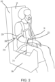
- Ejection seat 14 is illustrated with a bicep and/or wrist retention system 200, in accordance with various embodiments.
- Ejection seat 14 includes a seat back 102 and a seat pan 104.
- the ejection seat 14 comprises a bicep and/or wrist retention system 200.
- the bicep and/or wrist retention system 200 comprises a cord 210 and a cuff assembly 220.
- the bicep and/or wrist retention system 200 is configured to be coupled to an occupant 16 of an aircraft 12 from FIG. 1 .
- the cuff assembly 210 comprises a size adjuster, as described further herein, the size adjuster configured to adjust a diameter of a cuff in the cuff assembly 210 to secure the cuff assembly 210 to the occupant 16.
- the cord 210 of the bicep and/or wrist retention system extends from the cuff assembly 220 to a retraction mechanism as described further herein.
- the retraction mechanism is disposed within the seat back 102.
- the retraction mechanism may be disposed in the seat pan 104 and in a routed channel of the seat back 102.
- the retraction mechanism is configured to allow rapid movements by the occupant 16.
- the occupant 16 may be allowed to move about normally when reacting during flight of the aircraft 12 of FIG. 1 , in accordance with various embodiments.
- the retraction mechanism is configured to lock in response to an ejection event as described further herein.
- the present disclosure is not limited in this regard.
- coupling the cuff assembly 220 to a wrist is also within the scope of this disclosure.
- multiple cuffs may be utilized to couple to a wrist and a bicep of an arm of an occupant 16.
- the bicep and/or wrist retention system 200 may further comprise a second cord 211 in accordance with cord 210 and a second cuff assembly 221 in accordance with cuff assembly 220.
- the second cuff assembly 221 may be configured to couple to a wrist of an occupant 16 in accordance with various embodiments.
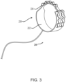
- the cuff assembly 220 may comprise a cuff 222 and a size adjuster 224.
- the size adjuster 224 may include a hook and loop fastener attachment mechanism, a belt and buckle attachment mechanism, a press fit connection or the like.
- the size adjuster 224 comprises webbing loops configured to secure the cuff 222 to an arm of an occupant 16 from FIG. 2 .
- the cuff assembly 220 is not limited in this regard.
- the cuff 222 may comprises a flexible sleeve configured to stretch during a process of coupling the cuff 222 to an arm of an occupant 16 and contract once the flexible sleeve is in place, in accordance with various embodiments.
- the retraction mechanism comprises a spool 232.
- the spool 232 comprises a generally cylindrical body 242 extending from a first flange 244 to a second flange 246.
- at least one of the first flange 244 or the second flange 246 comprises a plurality of teeth 248 extending radially outward from the first flange 244 and/or the second flange 246.
- the plurality of teeth 248 may be configured to interact with a locking mechanism 250 as described further herein.
- the cord 210 of the bicep and/or wrist retention system 200 is wound around the generally cylindrical body 242 of the spool 232.
- the bicep and/or wrist retention system 200 does not include a spring or other mechanism configured to keep the cord taut.
- the bicep and/or wrist retention system 200 is configured to allow uninhibited movement of an arm of an occupant 16 during operation of the aircraft 12 from FIG. 1 .
- the retraction mechanism 230 of the bicep and/or wrist retention system 200 further comprises a locking mechanism 250.
- the locking mechanism 250 may comprise an actuator 252 or the like configured to actuate a locking component 254 configured to engage the plurality of teeth 248 in response to an ejection event as described further herein.
- the actuator 252 may be activated electronically (e.g., electrically or wirelessly) via a sequencer, or ballistically (e.g., via a catapult pressure or the like) as described further herein.
- the retraction mechanism 230 further comprises a motor 260 powered by pressure from the catapult.
- the motor 260 is operably coupled to the spool 232.
- the motor 260 may be commanded to retract the cord 210 to a predetermined position (i.e., proximate the seat back).
- the actuator 252 of the locking mechanism 250 may be commanded to engage a groove defined between adjacent teeth in the plurality of teeth 248.
- the retraction mechanism 230 is configured to retract the cuff assembly 220 from FIGs.
- the retraction mechanism 230 comprises an inertia reel.
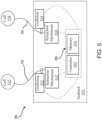
- control system 500 comprises a controller 502 and a memory 504.
- controller 502 may be integrated into computer systems of ejection seat 14.
- controller 502 may be configured as a central network element or hub to access various systems and components of control system 500.
- controller 502 may comprise a processor.
- controller 502 may be implemented in a single processor.
- controller 502 may be implemented as and may include one or more processors and/or one or more tangible, non-transitory memories (e.g., memory 504) and be capable of implementing logic.
- processors can be a general purpose processor, a digital signal processor (DSP), an application specific integrated circuit (ASIC), a field programmable gate array (FPGA) or other programmable logic device, discrete gate or transistor logic, discrete hardware components, or any combination thereof.
- Controller 502 may comprise a processor configured to implement various logical operations in response to execution of instructions, for example, instructions stored on a non-transitory, tangible, computer-readable medium configured to communicate with controller 502.
- System program instructions and/or controller instructions may be loaded onto a non-transitory, tangible computer-readable medium having instructions stored thereon that, in response to execution by a controller, cause the controller to perform various operations.
- the controller 502 is in electronic communication (e.g., wirelessly or electrically) with a first retraction mechanism 512, a first guillotine 522, a second retraction mechanism 514, and a second guillotine 524.
- the retraction mechanisms 512, 514 are in accordance with the retraction mechanism 230 of FIG. 4 .
- the guillotines 522, 524 are configured to sever a respective cord 542, 544 of a respective bicep and/or wrist retention system 200 in response to receiving a control signal from controller 502 in accordance with various embodiments.
- the guillotines may include an electrically activated actuator configured to release a cutting component and sever the respective cord 542, 544 as described further herein.
- an electrically activated actuator configured to release a cutting component and sever the respective cord 542, 544 as described further herein.
- cord 542 extending from a retraction mechanism 512 and cord 544 extending from a retraction mechanism 514
- the present disclosure is not limited in this regard.
- a single cord may extend from a single retraction mechanism and then split into cord 542 and 544, in accordance with various embodiments.
- only a single guillotine could be utilized as well, in accordance with various embodiments.
- the guillotines 522, 524 and the retraction mechanisms 512, 514 are disposed in the seat back 102.
- the guillotines 522, 524 and the retraction mechanisms 512, 514 may be hidden from view, in accordance with various embodiments.
- the controller 502 and the memory 504 may be components of an electronic sequencer for ejection system 10 from FIG. 1 .
- an electronic sequencer of an ejection system 10 is configured to initiate a sequence of events in response to an ejection handle being pulled (i.e., an ejection event being initiated).
- An electronic sequencer may initiate deployment of a drogue gun, a parachute, a stabilization firing system, etc., in accordance with various embodiments.
- the process 600 comprises, receiving, via a processor, an ejection initiation signal (step 602).
- the ejection initiation signal may be received in response to an occupant (e.g., occupant 16 from FIG. 1 ) pulling an ejection handle or the like.
- the process 600 further comprises commanding, via the processor, retraction of a first cord 542 and a second cord 544 (step 604).
- the cords 542, 544 are in accordance with the cord 210 from FIGs. 2 and 3 .
- the first cord 542 may be retracted via a first retraction mechanism 512 and the second cord 544 may be retracted via second retraction mechanism 514.
- the first cord 542 and the second cord 544 may be retracted via a single retraction mechanism.
- the present disclosure is not limited in this regard.
- arms of an occupant 16 may be better secured, preventing flailing of arms during the ejection event, in accordance with various embodiments.
- the cords 542, 544 may retract the respective cuffs 532, 534 to between flush with the seat back 102 and a foot (30.5 cm) from the seat back, or between flush with the seat back 102 and 6 inches (15 cm) from the seat back.
- the process 600 further comprises commanding, via the processor, locking of the first cord 542 and the second cord 544 (step 606).
- first cord 542 is locked by a first locking mechanism (e.g., a locking mechanism 250) and the second cord 544 is locked by a second locking mechanism (e.g., a locking mechanism 250).
- second locking mechanism e.g., a locking mechanism 250
- the first cord 542 and the second cord 544 may be locked by a single locking mechanism. The present disclosure is not limited in this regard.
- the process 600 further comprises commanding, via the processor, severing of the first cord 542 and the second cord 544 (step 608).
- the cords 542, 544 may be commanded to be severed in accordance with step 608 based on an event in the ejection process.
- the severing step 608 may occur simultaneously with a parachute being deployed, or a drogue chute being deployed, or the like.
- the severing step 608 may be performed just prior, in accordance with various embodiments.
- the control system 700 may comprise the controller 502 and the memory 504 as disclosed previously herein, and the control system 700 may further comprise a catapult 706.
- the catapult 706 may include a propulsion system configured to eject the occupant 16 from an aircraft 12 as illustrated in FIG. 1 .
- pressure generated from the catapult 706 may be utilized to operate the retraction mechanisms 712, 714 of the respective bicep and/or wrist retention devices 702, 704.
- pressure generated from the catapult 706 may be utilized to wind up the spool of the retraction mechanism 230 and lock the retraction mechanism 230 in place, in accordance with various embodiments.
- steps 604 and 606 by the controller 502 may be eliminated, in accordance with various embodiments.
- references to "various embodiments”, “one embodiment”, “an embodiment”, “an example embodiment”, etc. indicate that the embodiment described may include a particular feature, structure, or characteristic, but every embodiment may not necessarily include the particular feature, structure, or characteristic. Moreover, such phrases are not necessarily referring to the same embodiment. Further, when a particular feature, structure, or characteristic is described in connection with an embodiment, it is submitted that it is within the knowledge of one skilled in the art to affect such feature, structure, or characteristic in connection with other embodiments whether or not explicitly described. After reading the description, it will be apparent to one skilled in the relevant art(s) how to implement the disclosure in alternative embodiments.
Landscapes
- Business, Economics & Management (AREA)
- Emergency Management (AREA)
- Engineering & Computer Science (AREA)
- Aviation & Aerospace Engineering (AREA)
- Seats For Vehicles (AREA)
Claims (14)
- Luftfahrzeugschleudersystem, umfassend:einen Schleudersitz (14);ein Katapult, das dazu konfiguriert ist, den Schleudersitz aus dem Luftfahrzeug herauszuschleudern;eine Manschettenbaugruppe (320);einen Rückzugsmechanismus;eine Reißleine (542), die sich von dem Rückzugsmechanismus zu der Manschettenbaugruppe erstreckt, wobei der Rückzugsmechanismus dazu konfiguriert ist, den Druck von dem Katapult zum Zurückziehen der Reißleine zu nutzen;eine Guillotine, die dazu konfiguriert ist, die Reißleine zu durchtrennen; undeine Steuerung in Wirkverbindung mit der Guillotine, wobei die Steuerung zu Folgendem konfiguriert ist:Empfangen (602) eines Herausschleudereinleitungssignals über einen Prozessor, das angibt, dass ein Herausschleuderereignis eines Schleudersitzes eingeleitet wurde; undBefehlen (608) des Durchtrennens der Reißleine nach dem Herausschleudern des Schleudersitzes über den Prozessor.
- System nach Anspruch 1, wobei die Steuerung in Wirkverbindung mit dem Rückzugsmechanismus steht, die Steuerung ferner dazu konfiguriert ist, dem Rückzugsmechanismus ein Zurückziehen der Reißleine als Reaktion auf ein Einleiten des Herausschleuderereignisses zu befehlen.
- System nach Anspruch 2, wobei die Steuerung ferner dazu konfiguriert ist, dem Rückzugsmechanismus ein Sperren der Reißleine als Reaktion auf das Einleiten des Herausschleuderereignisses zu befehlen, und wobei die Manschettenbaugruppe optional als Reaktion auf das Sperren des Rückzugsmechanismus zwischen einer Position bündig mit einer Rückenlehne und einer Position ein Fuß (35 cm) von der Rückenlehne entfernt angeordnet ist.
- System nach einem der Ansprüche 1 bis 3, ferner umfassend eine zweite Manschettenbaugruppe (221), die an die Reißleine gekoppelt ist.
- System nach Anspruch 1,
wobei die Manschettenbaugruppe eine erste Manschettenbaugruppe (220) umfasst, die auf einer ersten Seite eines Schleudersitzes angeordnet ist; wobei das System ferner umfasst:eine zweite Manschettenbaugruppe (221), die auf einer zweiten Seite des Schleudersitzes angeordnet ist;und wobei die Reißleine eine erste Reißleine (542) umfasst, die sich von dem Inneren des Schleudersitzes zu der ersten Manschettenbaugruppe (220) erstreckt; wobei das System ferner umfasst:
eine zweite Reißleine (544), die sich von dem Inneren des Schleudersitzes zu der zweiten Manschettenbaugruppe (221) erstreckt, wobei das System dazu konfiguriert ist, einen freien Bewegungsbereich der ersten Manschettenbaugruppe (220) und der zweiten Manschettenbaugruppe (221) während eines Luftfahrzeugfluges zuzulassen, wobei das System dazu konfiguriert ist, die erste Manschettenbaugruppe (220) und die zweite Manschettenbaugruppe (221) als Reaktion auf das Einleiten eines Sitzherausschleuderns zurückzuziehen und zu sperren. - System nach Anspruch 5, wobei der Rückzugsmechanismus in einer Rückenlehne des Schleudersitzes angeordnet ist, der Rückzugsmechanismus dazu konfiguriert ist, die erste Reißleine (542) zurückzuziehen.
- System nach Anspruch 5 oder 6, ferner umfassend eine erste Guillotine (522) und eine zweite Guillotine (524), wobei die erste Guillotine (522) zum Durchtrennen der ersten Reißleine (542) während eines Sitzherausschleudervorgangs konfiguriert ist und die zweite Guillotine (524) zum Durchtrennen der zweiten Reißleine (544) während eines Sitzherausschleudervorgangs konfiguriert ist.
- System nach einem der Ansprüche 5 bis 7, ferner umfassend einen ersten Rückzugsmechanismus, der an die erste Reißleine (542) wirkgekoppelt ist, und einen zweiten Rückzugsmechanismus, der an die zweite Reißleine (544) wirkgekoppelt ist, und wobei der erste Rückzugsmechanismus und der zweite Rückzugsmechanismus optional jeweils eine Spule umfassen, wobei die erste Reißleine (542) um die Spule des ersten Rückzugsmechanismus gewickelt ist, die zweite Reißleine (544) um die Spule des zweiten Rückzugsmechanismus gewickelt ist, und wobei der erste Rückzugsmechanismus und der zweite Rückzugsmechanismus optional jeweils ohne Feder sind.
- System nach einem der Ansprüche 5 bis 8, wobei die erste Manschettenbaugruppe (220) und die zweite Manschettenbaugruppe (221) jeweils eine Manschette und einen Größenversteller umfassen.
- Verfahren, umfassend:Empfangen eines Herausschleudereinleitungssignals über einen Prozessor, das angibt, dass ein Herausschleuderereignis für einen Schleudersitz eines Luftfahrzeugs eingeleitet wurde;Befehlen des Herausschleuderns des Schleudersitzes über ein Katapult als Reaktion auf das Herausschleudereinleitungssignal über den Prozessor, wobei ein Rückzugsmechanismus den Druck des Katapults zum Zurückziehen einer Manschettenbaugruppe nutzt; und Befehlen über den Prozessor, dass eine Guillotine eine mit der Manschettenbaugruppe verbundene Reißleine durchtrennt.
- Verfahren nach Anspruch 10, wobei die Guillotine die Reißleine nach dem Herausschleudern des Schleudersitzes aus dem Luftfahrzeug durchtrennt.
- Verfahren nach Anspruch 10 oder 11, ferner umfassend Befehlen über den Prozessor, dass ein zweiter Rückzugsmechanismus eine zweite Manschettenbaugruppe (221) gleichzeitig mit der Manschettenbaugruppe in Richtung der Rückenlehne des Schleudersitzes zurückzieht.
- Verfahren nach einem der Ansprüche 10 bis 12, wobei die Manschettenbaugruppe an einen Bizeps und/oder ein Handgelenk eines Insassen gekoppelt ist.
- Verfahren nach einem der Ansprüche 10 bis 13, ferner umfassend Befehlen des Sperrens des Rückzugsmechanismus über den Prozessor, wobei der Rückzugsmechanismus optional die Manschettenbaugruppe zwischen einer Position bündig mit einer Rückenlehne und einer Position 30,5 cm (ein Fuß) von der Rückenlehne entfernt sperrt.
Applications Claiming Priority (1)
| Application Number | Priority Date | Filing Date | Title |
|---|---|---|---|
| US17/462,420 US11851194B2 (en) | 2021-08-31 | 2021-08-31 | Retention systems and methods for ejection seats |
Publications (2)
| Publication Number | Publication Date |
|---|---|
| EP4140894A1 EP4140894A1 (de) | 2023-03-01 |
| EP4140894B1 true EP4140894B1 (de) | 2024-12-18 |
Family
ID=82748487
Family Applications (1)
| Application Number | Title | Priority Date | Filing Date |
|---|---|---|---|
| EP22187321.9A Active EP4140894B1 (de) | 2021-08-31 | 2022-07-27 | Rückhaltesysteme und verfahren für schleudersitze |
Country Status (2)
| Country | Link |
|---|---|
| US (1) | US11851194B2 (de) |
| EP (1) | EP4140894B1 (de) |
Families Citing this family (2)
| Publication number | Priority date | Publication date | Assignee | Title |
|---|---|---|---|---|
| US12037123B2 (en) | 2022-06-15 | 2024-07-16 | Rockwell Collins, Inc. | Ejection seat handle separation |
| CN117163297B (zh) * | 2023-09-18 | 2025-10-21 | 航宇救生装备有限公司 | 惯导故障工况下的火箭弹射座椅控制方法及系统 |
Family Cites Families (14)
| Publication number | Priority date | Publication date | Assignee | Title |
|---|---|---|---|---|
| US2940701A (en) * | 1958-06-16 | 1960-06-14 | North American Aviation Inc | Personnel escape equipment |
| US3074669A (en) * | 1959-08-28 | 1963-01-22 | Svenska Aeroplan Ab | Device to protect an occupant against bodily injury during emergency escape from aircraft |
| GB996635A (en) * | 1963-02-18 | 1965-06-30 | Martin James | Improvements relating to vehicle ejection seats |
| US3329464A (en) * | 1965-04-22 | 1967-07-04 | Barwood Antony John | Body restraints |
| GB1099490A (en) | 1965-11-01 | 1968-01-17 | Martin James | Improvements relating to vehicle ejection seats |
| GB1456007A (en) | 1973-05-11 | 1976-11-17 | Martin J | Restraining means in vehicle ejection seats |
| GB1481791A (en) * | 1973-07-17 | 1977-08-03 | Secr Defence | Arm restraint system for an ejection seat |
| US4179086A (en) * | 1978-07-20 | 1979-12-18 | The United States Of America As Represented By The Secretary Of The Air Force | Army restraint system |
| US4247064A (en) | 1979-06-06 | 1981-01-27 | The United States Of America As Represented By The Secretary Of The Navy | Limb retention system |
| US4462563A (en) | 1982-10-08 | 1984-07-31 | The United States Of America As Represented By The Secretary Of The Air Force | Simple nonrestrictive arm restraint system |
| USH115H (en) | 1986-02-03 | 1986-08-05 | The United States Of America As Represented By The Secretary Of The Navy | Arm restraint system for harness mounting |
| US5072897A (en) | 1990-08-15 | 1991-12-17 | Grumman Aerospace Corporation | Pilot harness fitting incorporating restraints for arms, legs, and aid of gravity |
| US6292945B1 (en) * | 1999-08-31 | 2001-09-25 | The B. F. Goodrich Company | Ejection restraint systems for flight suits |
| US7717216B2 (en) * | 2003-06-20 | 2010-05-18 | Roelof T.I Van Rooyen | Automatic safety belt release |
-
2021
- 2021-08-31 US US17/462,420 patent/US11851194B2/en active Active
-
2022
- 2022-07-27 EP EP22187321.9A patent/EP4140894B1/de active Active
Also Published As
| Publication number | Publication date |
|---|---|
| US20230063264A1 (en) | 2023-03-02 |
| EP4140894A1 (de) | 2023-03-01 |
| US11851194B2 (en) | 2023-12-26 |
Similar Documents
| Publication | Publication Date | Title |
|---|---|---|
| US10414506B2 (en) | Aircraft parachute system utilizing airbag to assist with parachute deployment | |
| EP4140894A1 (de) | Rückhaltesysteme und verfahren für schleudersitze | |
| US10946970B2 (en) | Systems for removal of parachute assembly head restraints | |
| US20110121138A1 (en) | Low payload weight parachute release-away static line | |
| EP3378778B1 (de) | Wiederverwendbare evakuierungssystemhalterung | |
| EP3348481B1 (de) | Zusätzliche trennvorrichtung für notrutschen | |
| US7648105B2 (en) | Deployment brake release for a parachute | |
| EP3406524A1 (de) | Evakuierungssystem mit einem ausfahrbaren kopfende | |
| EP3647197A1 (de) | Manuelles fallschirmbetätigungssystem für den notfall | |
| EP3348482A1 (de) | Leichtgewichtiges halteelement für notrutschensysteme | |
| EP3495271B1 (de) | Flugzeugrückhaltesysteme mit nicht fixiertem standardmodus | |
| US3027126A (en) | Ejection seat for aircraft | |
| US11279495B2 (en) | Leg restraint system for ejection seats | |
| US2955786A (en) | Foot retraction apparatus | |
| EP3075659B1 (de) | Schleudersitzstabilisierungsbremsschirm zur apogäumsverbesserung | |
| US11136098B2 (en) | Integrated lifeline and geometric restraint | |
| EP3348485B1 (de) | Fortlaufende haltevorrichtung für notrutschensystem | |
| US6292945B1 (en) | Ejection restraint systems for flight suits | |
| US3672609A (en) | Inflatable body-attachments for marine life-saving | |
| GB2622143A (en) | Parachute assemblies with multi-stage reefing | |
| US20230062602A1 (en) | Electronic release systems and methods for ejection seats | |
| US11345477B2 (en) | Adjustable preload severance cutter for ejection systems | |
| US20260001650A1 (en) | Rigid tube stabilizer system for parachute deployment | |
| US8162259B2 (en) | Aircraft ejection seat with passive limb retention | |
| WO2025147292A2 (en) | Systems and methods for accelerating the inflation of a parachute canopy |
Legal Events
| Date | Code | Title | Description |
|---|---|---|---|
| PUAI | Public reference made under article 153(3) epc to a published international application that has entered the european phase |
Free format text: ORIGINAL CODE: 0009012 |
|
| STAA | Information on the status of an ep patent application or granted ep patent |
Free format text: STATUS: THE APPLICATION HAS BEEN PUBLISHED |
|
| AK | Designated contracting states |
Kind code of ref document: A1 Designated state(s): AL AT BE BG CH CY CZ DE DK EE ES FI FR GB GR HR HU IE IS IT LI LT LU LV MC MK MT NL NO PL PT RO RS SE SI SK SM TR |
|
| STAA | Information on the status of an ep patent application or granted ep patent |
Free format text: STATUS: REQUEST FOR EXAMINATION WAS MADE |
|
| 17P | Request for examination filed |
Effective date: 20230817 |
|
| RBV | Designated contracting states (corrected) |
Designated state(s): AL AT BE BG CH CY CZ DE DK EE ES FI FR GB GR HR HU IE IS IT LI LT LU LV MC MK MT NL NO PL PT RO RS SE SI SK SM TR |
|
| P01 | Opt-out of the competence of the unified patent court (upc) registered |
Effective date: 20230922 |
|
| RIC1 | Information provided on ipc code assigned before grant |
Ipc: B64D 25/10 20060101AFI20240620BHEP |
|
| GRAP | Despatch of communication of intention to grant a patent |
Free format text: ORIGINAL CODE: EPIDOSNIGR1 |
|
| STAA | Information on the status of an ep patent application or granted ep patent |
Free format text: STATUS: GRANT OF PATENT IS INTENDED |
|
| INTG | Intention to grant announced |
Effective date: 20240730 |
|
| GRAS | Grant fee paid |
Free format text: ORIGINAL CODE: EPIDOSNIGR3 |
|
| GRAA | (expected) grant |
Free format text: ORIGINAL CODE: 0009210 |
|
| STAA | Information on the status of an ep patent application or granted ep patent |
Free format text: STATUS: THE PATENT HAS BEEN GRANTED |
|
| AK | Designated contracting states |
Kind code of ref document: B1 Designated state(s): AL AT BE BG CH CY CZ DE DK EE ES FI FR GB GR HR HU IE IS IT LI LT LU LV MC MK MT NL NO PL PT RO RS SE SI SK SM TR |
|
| REG | Reference to a national code |
Ref country code: CH Ref legal event code: EP |
|
| REG | Reference to a national code |
Ref country code: DE Ref legal event code: R096 Ref document number: 602022008780 Country of ref document: DE |
|
| REG | Reference to a national code |
Ref country code: IE Ref legal event code: FG4D |
|
| REG | Reference to a national code |
Ref country code: LT Ref legal event code: MG9D |
|
| PG25 | Lapsed in a contracting state [announced via postgrant information from national office to epo] |
Ref country code: HR Free format text: LAPSE BECAUSE OF FAILURE TO SUBMIT A TRANSLATION OF THE DESCRIPTION OR TO PAY THE FEE WITHIN THE PRESCRIBED TIME-LIMIT Effective date: 20241218 |
|
| PG25 | Lapsed in a contracting state [announced via postgrant information from national office to epo] |
Ref country code: FI Free format text: LAPSE BECAUSE OF FAILURE TO SUBMIT A TRANSLATION OF THE DESCRIPTION OR TO PAY THE FEE WITHIN THE PRESCRIBED TIME-LIMIT Effective date: 20241218 |
|
| PG25 | Lapsed in a contracting state [announced via postgrant information from national office to epo] |
Ref country code: BG Free format text: LAPSE BECAUSE OF FAILURE TO SUBMIT A TRANSLATION OF THE DESCRIPTION OR TO PAY THE FEE WITHIN THE PRESCRIBED TIME-LIMIT Effective date: 20241218 |
|
| PG25 | Lapsed in a contracting state [announced via postgrant information from national office to epo] |
Ref country code: NO Free format text: LAPSE BECAUSE OF FAILURE TO SUBMIT A TRANSLATION OF THE DESCRIPTION OR TO PAY THE FEE WITHIN THE PRESCRIBED TIME-LIMIT Effective date: 20250318 |
|
| REG | Reference to a national code |
Ref country code: NL Ref legal event code: MP Effective date: 20241218 |
|
| PG25 | Lapsed in a contracting state [announced via postgrant information from national office to epo] |
Ref country code: GR Free format text: LAPSE BECAUSE OF FAILURE TO SUBMIT A TRANSLATION OF THE DESCRIPTION OR TO PAY THE FEE WITHIN THE PRESCRIBED TIME-LIMIT Effective date: 20250319 Ref country code: LV Free format text: LAPSE BECAUSE OF FAILURE TO SUBMIT A TRANSLATION OF THE DESCRIPTION OR TO PAY THE FEE WITHIN THE PRESCRIBED TIME-LIMIT Effective date: 20241218 |
|
| PG25 | Lapsed in a contracting state [announced via postgrant information from national office to epo] |
Ref country code: RS Free format text: LAPSE BECAUSE OF FAILURE TO SUBMIT A TRANSLATION OF THE DESCRIPTION OR TO PAY THE FEE WITHIN THE PRESCRIBED TIME-LIMIT Effective date: 20250318 |
|
| PG25 | Lapsed in a contracting state [announced via postgrant information from national office to epo] |
Ref country code: NL Free format text: LAPSE BECAUSE OF FAILURE TO SUBMIT A TRANSLATION OF THE DESCRIPTION OR TO PAY THE FEE WITHIN THE PRESCRIBED TIME-LIMIT Effective date: 20241218 |
|
| REG | Reference to a national code |
Ref country code: AT Ref legal event code: MK05 Ref document number: 1752071 Country of ref document: AT Kind code of ref document: T Effective date: 20241218 |
|
| PG25 | Lapsed in a contracting state [announced via postgrant information from national office to epo] |
Ref country code: SM Free format text: LAPSE BECAUSE OF FAILURE TO SUBMIT A TRANSLATION OF THE DESCRIPTION OR TO PAY THE FEE WITHIN THE PRESCRIBED TIME-LIMIT Effective date: 20241218 |
|
| PG25 | Lapsed in a contracting state [announced via postgrant information from national office to epo] |
Ref country code: PL Free format text: LAPSE BECAUSE OF FAILURE TO SUBMIT A TRANSLATION OF THE DESCRIPTION OR TO PAY THE FEE WITHIN THE PRESCRIBED TIME-LIMIT Effective date: 20241218 |
|
| PG25 | Lapsed in a contracting state [announced via postgrant information from national office to epo] |
Ref country code: ES Free format text: LAPSE BECAUSE OF FAILURE TO SUBMIT A TRANSLATION OF THE DESCRIPTION OR TO PAY THE FEE WITHIN THE PRESCRIBED TIME-LIMIT Effective date: 20241218 |
|
| PG25 | Lapsed in a contracting state [announced via postgrant information from national office to epo] |
Ref country code: IS Free format text: LAPSE BECAUSE OF FAILURE TO SUBMIT A TRANSLATION OF THE DESCRIPTION OR TO PAY THE FEE WITHIN THE PRESCRIBED TIME-LIMIT Effective date: 20250418 |
|
| PG25 | Lapsed in a contracting state [announced via postgrant information from national office to epo] |
Ref country code: PT Free format text: LAPSE BECAUSE OF FAILURE TO SUBMIT A TRANSLATION OF THE DESCRIPTION OR TO PAY THE FEE WITHIN THE PRESCRIBED TIME-LIMIT Effective date: 20250421 |
|
| PG25 | Lapsed in a contracting state [announced via postgrant information from national office to epo] |
Ref country code: EE Free format text: LAPSE BECAUSE OF FAILURE TO SUBMIT A TRANSLATION OF THE DESCRIPTION OR TO PAY THE FEE WITHIN THE PRESCRIBED TIME-LIMIT Effective date: 20241218 |
|
| PGFP | Annual fee paid to national office [announced via postgrant information from national office to epo] |
Ref country code: FR Payment date: 20250620 Year of fee payment: 4 |
|
| PG25 | Lapsed in a contracting state [announced via postgrant information from national office to epo] |
Ref country code: RO Free format text: LAPSE BECAUSE OF FAILURE TO SUBMIT A TRANSLATION OF THE DESCRIPTION OR TO PAY THE FEE WITHIN THE PRESCRIBED TIME-LIMIT Effective date: 20241218 Ref country code: AT Free format text: LAPSE BECAUSE OF FAILURE TO SUBMIT A TRANSLATION OF THE DESCRIPTION OR TO PAY THE FEE WITHIN THE PRESCRIBED TIME-LIMIT Effective date: 20241218 |
|
| PG25 | Lapsed in a contracting state [announced via postgrant information from national office to epo] |
Ref country code: SK Free format text: LAPSE BECAUSE OF FAILURE TO SUBMIT A TRANSLATION OF THE DESCRIPTION OR TO PAY THE FEE WITHIN THE PRESCRIBED TIME-LIMIT Effective date: 20241218 |
|
| PG25 | Lapsed in a contracting state [announced via postgrant information from national office to epo] |
Ref country code: CZ Free format text: LAPSE BECAUSE OF FAILURE TO SUBMIT A TRANSLATION OF THE DESCRIPTION OR TO PAY THE FEE WITHIN THE PRESCRIBED TIME-LIMIT Effective date: 20241218 |
|
| PG25 | Lapsed in a contracting state [announced via postgrant information from national office to epo] |
Ref country code: IT Free format text: LAPSE BECAUSE OF FAILURE TO SUBMIT A TRANSLATION OF THE DESCRIPTION OR TO PAY THE FEE WITHIN THE PRESCRIBED TIME-LIMIT Effective date: 20241218 |
|
| PG25 | Lapsed in a contracting state [announced via postgrant information from national office to epo] |
Ref country code: SE Free format text: LAPSE BECAUSE OF FAILURE TO SUBMIT A TRANSLATION OF THE DESCRIPTION OR TO PAY THE FEE WITHIN THE PRESCRIBED TIME-LIMIT Effective date: 20241218 |
|
| REG | Reference to a national code |
Ref country code: DE Ref legal event code: R097 Ref document number: 602022008780 Country of ref document: DE |
|
| PG25 | Lapsed in a contracting state [announced via postgrant information from national office to epo] |
Ref country code: DK Free format text: LAPSE BECAUSE OF FAILURE TO SUBMIT A TRANSLATION OF THE DESCRIPTION OR TO PAY THE FEE WITHIN THE PRESCRIBED TIME-LIMIT Effective date: 20241218 |
|
| PGFP | Annual fee paid to national office [announced via postgrant information from national office to epo] |
Ref country code: DE Payment date: 20250620 Year of fee payment: 4 |
|
| PLBE | No opposition filed within time limit |
Free format text: ORIGINAL CODE: 0009261 |
|
| STAA | Information on the status of an ep patent application or granted ep patent |
Free format text: STATUS: NO OPPOSITION FILED WITHIN TIME LIMIT |
|
| REG | Reference to a national code |
Ref country code: CH Ref legal event code: L10 Free format text: ST27 STATUS EVENT CODE: U-0-0-L10-L00 (AS PROVIDED BY THE NATIONAL OFFICE) Effective date: 20251029 |
|
| 26N | No opposition filed |
Effective date: 20250919 |
|
| REG | Reference to a national code |
Ref country code: CH Ref legal event code: H13 Free format text: ST27 STATUS EVENT CODE: U-0-0-H10-H13 (AS PROVIDED BY THE NATIONAL OFFICE) Effective date: 20260224 |
|
| PG25 | Lapsed in a contracting state [announced via postgrant information from national office to epo] |
Ref country code: LU Free format text: LAPSE BECAUSE OF NON-PAYMENT OF DUE FEES Effective date: 20250727 |
|
| REG | Reference to a national code |
Ref country code: BE Ref legal event code: MM Effective date: 20250731 |
|
| PG25 | Lapsed in a contracting state [announced via postgrant information from national office to epo] |
Ref country code: BE Free format text: LAPSE BECAUSE OF NON-PAYMENT OF DUE FEES Effective date: 20250731 |
|
| PG25 | Lapsed in a contracting state [announced via postgrant information from national office to epo] |
Ref country code: CH Free format text: LAPSE BECAUSE OF NON-PAYMENT OF DUE FEES Effective date: 20250731 |