EP4074452B1 - Head for friction stir welding and method using such welding head - Google Patents
Head for friction stir welding and method using such welding head Download PDFInfo
- Publication number
- EP4074452B1 EP4074452B1 EP22166634.0A EP22166634A EP4074452B1 EP 4074452 B1 EP4074452 B1 EP 4074452B1 EP 22166634 A EP22166634 A EP 22166634A EP 4074452 B1 EP4074452 B1 EP 4074452B1
- Authority
- EP
- European Patent Office
- Prior art keywords
- rotation
- axis
- central
- shaft
- rotary shaft
- Prior art date
- Legal status (The legal status is an assumption and is not a legal conclusion. Google has not performed a legal analysis and makes no representation as to the accuracy of the status listed.)
- Active
Links
- 238000003466 welding Methods 0.000 title claims description 80
- 238000003756 stirring Methods 0.000 title claims description 28
- 238000000034 method Methods 0.000 title claims description 11
- 230000002093 peripheral effect Effects 0.000 claims description 80
- 230000008878 coupling Effects 0.000 claims description 45
- 238000010168 coupling process Methods 0.000 claims description 45
- 238000005859 coupling reaction Methods 0.000 claims description 45
- 230000005540 biological transmission Effects 0.000 claims description 31
- 230000007246 mechanism Effects 0.000 claims description 30
- 230000000903 blocking effect Effects 0.000 claims description 15
- 230000009466 transformation Effects 0.000 claims description 12
- 230000001131 transforming effect Effects 0.000 claims description 3
- 241000920340 Pion Species 0.000 description 17
- 238000005242 forging Methods 0.000 description 4
- 230000008569 process Effects 0.000 description 4
- 230000006835 compression Effects 0.000 description 3
- 238000007906 compression Methods 0.000 description 3
- 238000003754 machining Methods 0.000 description 2
- 239000000463 material Substances 0.000 description 2
- 230000006978 adaptation Effects 0.000 description 1
- 230000008859 change Effects 0.000 description 1
- 210000000078 claw Anatomy 0.000 description 1
- 230000007547 defect Effects 0.000 description 1
- 239000012636 effector Substances 0.000 description 1
- 238000004898 kneading Methods 0.000 description 1
- 238000003908 quality control method Methods 0.000 description 1
- 230000000630 rising effect Effects 0.000 description 1
- 238000005096 rolling process Methods 0.000 description 1
Images


Classifications
-
- B—PERFORMING OPERATIONS; TRANSPORTING
- B23—MACHINE TOOLS; METAL-WORKING NOT OTHERWISE PROVIDED FOR
- B23K—SOLDERING OR UNSOLDERING; WELDING; CLADDING OR PLATING BY SOLDERING OR WELDING; CUTTING BY APPLYING HEAT LOCALLY, e.g. FLAME CUTTING; WORKING BY LASER BEAM
- B23K20/00—Non-electric welding by applying impact or other pressure, with or without the application of heat, e.g. cladding or plating
- B23K20/12—Non-electric welding by applying impact or other pressure, with or without the application of heat, e.g. cladding or plating the heat being generated by friction; Friction welding
- B23K20/122—Non-electric welding by applying impact or other pressure, with or without the application of heat, e.g. cladding or plating the heat being generated by friction; Friction welding using a non-consumable tool, e.g. friction stir welding
- B23K20/1245—Non-electric welding by applying impact or other pressure, with or without the application of heat, e.g. cladding or plating the heat being generated by friction; Friction welding using a non-consumable tool, e.g. friction stir welding characterised by the apparatus
- B23K20/1255—Tools therefor, e.g. characterised by the shape of the probe
-
- B—PERFORMING OPERATIONS; TRANSPORTING
- B23—MACHINE TOOLS; METAL-WORKING NOT OTHERWISE PROVIDED FOR
- B23K—SOLDERING OR UNSOLDERING; WELDING; CLADDING OR PLATING BY SOLDERING OR WELDING; CUTTING BY APPLYING HEAT LOCALLY, e.g. FLAME CUTTING; WORKING BY LASER BEAM
- B23K20/00—Non-electric welding by applying impact or other pressure, with or without the application of heat, e.g. cladding or plating
- B23K20/12—Non-electric welding by applying impact or other pressure, with or without the application of heat, e.g. cladding or plating the heat being generated by friction; Friction welding
- B23K20/122—Non-electric welding by applying impact or other pressure, with or without the application of heat, e.g. cladding or plating the heat being generated by friction; Friction welding using a non-consumable tool, e.g. friction stir welding
- B23K20/1245—Non-electric welding by applying impact or other pressure, with or without the application of heat, e.g. cladding or plating the heat being generated by friction; Friction welding using a non-consumable tool, e.g. friction stir welding characterised by the apparatus
- B23K20/125—Rotary tool drive mechanism
Definitions
- An objective of the invention is to obtain a friction stir welding head (and a friction stir welding method), which is provided with a retractable pin and which is compact and universal so that it can be mounted directly on machines -numerically controlled tools and compact machines or machining centers simply having a rotating drive spindle of the welding tool, to be able to plug the hole at the weld outlet between the two mechanical parts to be welded, to overcome the problems disadvantages mentioned above.
- the first rotation transmission device comprises a secondary shaft integral in rotation with the external interface part around the second axis of rotation, a first pulley fixed around the secondary shaft, a second pulley fixed around the rotary primary shaft and a rotation transmission belt between the first pulley and the second pulley to transmit the rotation of the external interface part around the second axis of rotation to the rotary primary shaft around the first axis of rotation.
- the motor comprises a tertiary shaft rotating around a third axis of rotation
- the second translation drive device comprises an intermediate shaft coaxial and offset relative to the central shaft, a mechanism for transmitting rotation of the rotating tertiary shaft around the third axis of rotation to the intermediate shaft around the first axis of rotation and a mechanism for transforming rotation of the intermediate shaft around the first axis of rotation in translation of the central shaft along the first axis of rotation.
- the tertiary shaft of the motor is rotatable around the third axis of rotation offset and transverse to the first axis of rotation
- the rotation transmission mechanism comprises an angle transmission mechanism of the tertiary shaft rotating around the third axis of rotation to the intermediate shaft around the first axis of rotation.
- the rotation transformation mechanism comprises a first threaded member, which is fixed to or formed by the intermediate shaft, a second threaded member, which is integral in translation with the central shaft the along the first axis of rotation, and a rotation blocking element of the second threaded member, the first threaded member cooperating by a screw connection with the second threaded member around the first axis of rotation, the blocking element being fixed to an inner plate, on which the intermediate shaft is rotatably mounted, the inner plate being mounted in the frame.
- the rotation transformation mechanism comprises a first threaded member, which is fixed to or formed by the intermediate shaft, a second threaded member, which is integral in translation with the central shaft along the first axis of rotation, and a rotation blocking element of the first threaded member, the first threaded member cooperating by a screw connection with the second threaded member around the first axis of rotation, the blocking element being fixed to an inner plate, on which the intermediate shaft is rotatably mounted, the inner plate being mounted in the frame, the first threaded member is a nut fixed to the intermediate shaft, the second threaded member is a screw, the nut being screwed around the screw.
- the rotation support bearing is a bearing assembly, comprising at least a first bearing part fixed in the second side of the sleeve and at least a second bearing part, which is fixed to the central shaft and which is rotatable relative to the first bearing part.
- the sleeve is inserted into an interior cavity of the rotary primary shaft and is movable in translation along the first axis of rotation in the interior cavity.
- the coupling device comprises a first coupling part fixed to the central rotating shaft and a second coupling part fixed in the shoulder fixing part, the first part d coupling cooperating by a sliding connection with the second coupling part along the first axis of rotation and solidarity in rotation with the second coupling part.
- the first coupling part projects from the central rotating shaft transversely to the first axis of rotation
- the second coupling part is a groove, which extends on an inner surface of the shoulder attachment part along the first axis of rotation and in which the first coupling part can be moved in translation along the first axis of rotation by being blocked in rotation around the first axis of rotation.
- the friction stir welding head 1 comprises a frame 300, intended to be fixed to a frame C of a machine M separate from the head 1, the welding head 1 having to be mounted on the machine M.
- This machine M can be a machine tool M, for example a numerically controlled machine tool M.
- the machine M includes a drive spindle B (or spindle nose B), which is rotatably mounted around an axis AX2 relative to the frame C.
- This friction stir welding tool O comprises a peripheral shoulder 100 and a rotating and retractable central pin 200, which is surrounded by the peripheral shoulder 100 around a first axis AX1 of rotation and which is capable of projecting relative to the peripheral shoulder 100 along the first axis AX1 of rotation.
- the shoulder peripheral 100 is separated from the central pin 200, that is to say that the peripheral shoulder 100 is not in one piece with the central pin 200.
- the peripheral shoulder 100 has a lower transverse welding surface 101 to the first axis AX1 of rotation, while the central pin 200 extends along the first axis AX1 of rotation.
- the first axis AX1 of rotation can for example be vertical and parallel to a vertical direction Z, oriented in the upward direction, to which a horizontal direction horizontal X, are perpendicular.
- friction stir welding (FSW for “Friction Stir Welding”) is carried out by rotating the peripheral shoulder 100 and the central pin 200 around the first axis AX1 of rotation (according to arrow R), to penetrate the central pin 200 in two (or more than two) pieces to be welded or pieces to be worked P1 and P2, until the shoulder 100 abuts against these pieces P1 and P2, then movement of the tool O according to a prescribed trajectory D along an LJ joint line to make the SFSW friction stir weld.
- the head 1 comprises a rotating central shaft 201 to which, in a mounting position of the tool O on the head 1, the central pin 200 is fixed.
- the head 1 comprises a shoulder fixing part 301 to which, in a mounting position of the tool O on the head 1, the peripheral shoulder 100 is fixed.
- the shoulder fixing part 301 is located around the central shaft 201, which exceeds this shoulder fixing part 301 upwards, as shown in figures 5 , 6 And 8 .
- the shoulder fixing part 301 is centered on the same axis AX1 as the rotating central shaft 201.
- the shoulder fixing part 301 can for example be circular.
- the mechanical coupling system 400 in mechanical rotation between the part 201 and the part 301 allows a degree of freedom in translation between the part 201 and the part 301.
- the shoulder fixing part 301 is fixed to the rotary primary shaft 302 drive, for example by removable fixing means 304 operable from the outside, which may for example be one or more external screws 304.
- removable fixing means 304 operable from the outside, which may for example be one or more external screws 304.
- the primary rotary drive shaft 302 is mounted by a rotation support bearing 322 or bearing (for example a ball bearing) on a lower part of a casing 321 of the frame 300. From this casing 321 protrude downwards the shoulder fixing part 301, the peripheral shoulder 100 and the central pin 200 when it protrudes from the peripheral shoulder 100.
- a rotation support bearing 322 or bearing for example a ball bearing
- the rotation of the spindle B of the machine M causes the rotation of the external interface part 350 around the second axis AX2 of rotation of this external interface part 350, which drives, via the first rotation transmission device 310, the rotation of the rotary primary shaft 302.
- Embodiments of this first rotation transmission device 310 are described below, as well as shown in figures 5 to 8 .
- the first rotation transmission device 310 comprises a secondary shaft 311 connected to and integral in rotation with the external interface part 350 around the second axis AX2 of rotation.
- a first pulley 312 is fixed to the secondary shaft 311 around the second axis AX2 of rotation
- a second pulley 313 is fixed to the primary rotating shaft 302 around the first axis AX1 of rotation
- a belt 314 for transmitting rotation is arranged around the first pulley 312 and around the second pulley 313.
- the belt 314 makes it possible to transmit the rotation of the external interface part 350 around the second axis AX2 of rotation to the rotary primary shaft 302 around the first axis AX1 of rotation .
- the first rotation transmission device 310 can be gear or other between the external interface part 350 and the rotary primary shaft 302.
- the head 1 comprises a motor 250 for actuating the retractable pin 200 and a second device 210 for driving the rotating central shaft 201 in translation along the first axis AX1 of rotation from the motor 250 and this during rotation of the central rotating shaft 201 and the shoulder fixing part 301 around the first axis AX1 of rotation and therefore during the rotation of the peripheral shoulder 100 and the central pin 200 around the first axis AX1 of rotation, when this peripheral shoulder 100 is mounted on the shoulder fixing part 301 and when this central pin 200 is mounted on the central rotating shaft 201.
- the second translation drive device 210 makes it possible to translate the central rotating shaft 201 relative to to the shoulder fixing part 301 and to the rotary primary shaft 302 of at least one low position of the central rotary shaft 201, shown in figures 1 , 2 , 3 , 5 , 11 And 13 , in which the lower end 202 of the central pin 200 projects downwards relative to the peripheral shoulder 100 and its lower surface 101 along the first axis AX1 of rotation, at a high position of the central rotating shaft 201 , represented at figures 6 , 12 And 14 , in which the central pin 200 does not protrude downwards relative to the peripheral shoulder 100 and its lower surface 101 along the first axis AX1 of rotation.
- step E3 the head 1 is lowered by the control device of the machine M, for example towards the part P1 and/or P2, to lower the peripheral shoulder 100 and the central pin 200 projecting out of the peripheral shoulder 100, which both rotate around the first axis AX1 of rotation, against the part P1 and/or P2.
- step E4 the raising of the central pin 200 in translation relative to the peripheral shoulder 100 so that the lower end 202 of the central pin 200 is lowered into an intermediate or low position or is raised into an intermediate position or retracted in the peripheral shoulder 100 in the high position (step E4), and this for example during the rotation of the first transmission device 310 around the second axis AX2 and during the rotation of the rotary primary shaft assembly 302, shoulder fixing part 301, pin central 200 and peripheral shoulder 100 around the first axis AX1 of rotation.
- the lower end 202 of the central pin 200 can be at the same level as the lower surface 101 of the peripheral shoulder 100 or at a level higher than the lower surface 101 of the peripheral shoulder 100.
- the raising of the central pin 200 at least up to the high position advantageously makes it possible to leave in the SFSW welding line an almost flat and horizontal surface, filled with material below the lower end 202 of the central pin 200 and below the peripheral shoulder 100, without leaving a hole in this SFSW weld line under it.
- head 1 is raised relative to parts P1 and P2 (step E5).
- the head 1 makes it possible to reach the forces necessary at the lower end 202 of the central pin 200 to carry out the filling of this hole or to weld several thicknesses in the same weld.
- the translation of the central pin 200 along the first axis AX1 could be implemented by offsetting the second rotational drive axis AX2 of the welding tool O thanks to the first rotation transmission device 310.
- the welding head 1 forms an effector 1.
- the upper surface 323 of the welding head 1 and/or the housing 500 is fixed to an adapter 600 (or adaptation part 600 or fixing part 600 ).
- the adapter 600 is fixed to the chassis C of the machine M.
- the welding head 1 and/or the upper surface 323 and/or the housing 500 may include fixing or assembly members 506, for fixing or assembling the head 1 of welding and/or the upper surface 323 and/or the housing 500 to the adapter 600.
- the adapter 600 may include fixing or assembly members 601, for fixing or assembling the adapter 600 to the chassis C of the machine M.
- the fixing members 506 can be or include for example screws 506 or bolts 506, or rods 506, or others.
- the fixing members 601 can be or include for example screws 601 or bolts 601, or rods 601, or others.
- the adapter 600 comprises a through hole 602 through which the external interface part 350 passes in the mounting position of the welding head 1 on the machine M. In the mounting position of the welding head 1 on the machine M , the external interface part 350 is fixed to spindle B of machine M, for example by a mechanical coupling. In the mounting position of the welding head 1 on the machine M, the adapter 600 is located between the frame C and the upper surface 323.
- the adapter 600 is in one piece with the housing 500 of the welding head 1 and is inseparable from the housing 500 of the welding head 1.
- the fixing members 506 are not provided.
- the motor 250 comprises a tertiary shaft 251 rotating around a third axis AX3 of rotation.
- the second translation drive device 210 comprises an intermediate shaft 221, which is offset above the central shaft 201 and which is coaxial with the first axis AX1 of rotation.
- a mechanism 220 for transmitting rotation of the rotary tertiary shaft 251 of the motor 250 around its third axis AX3 of rotation to the intermediate shaft 221 around the first axis AX1 of rotation is provided in the second translation drive device 210 .
- a mechanism 230 for transforming the rotation of the intermediate shaft 221 around the first axis AX1 of rotation into a translation of the central shaft 201 along the first axis AX1 of rotation is provided in the second device 210 of translational drive.
- the third axis AX3 of rotation of the tertiary shaft 251 of the motor 250 is offset and transverse to the first axis AX1 of rotation, and can for example make a non-zero angle and for example perpendicular to the first axis AX1 of rotation.
- the rotation transmission mechanism 220 comprises an angle transmission mechanism 225 from the tertiary shaft 251 rotating around the third axis AX3 of rotation to the intermediate shaft 221 around the first axis AX1 of rotation.
- the angle transmission mechanism 225 of the rotary tertiary shaft 251 comprises at least one first meshing member 222 fixed to the tertiary shaft 251 and at least one second meshing member 223 fixed to the intermediate shaft 221 and meshing with the first meshing member 222, the second meshing member 223 being rotated around the first axis AX1 of rotation by the rotation of the first meshing member 222 around the third axis AX3 of rotation, these members 22 and 223 forming an angle gear.
- the intermediate shaft 221 is rotatably mounted around the first axis AX1 of rotation without possible translation along this first axis AX1 of rotation on an internal plate 226, which is mounted in the frame 300 and is fixed to the casing 321.
- intermediate shaft 221 can be mounted by a rotation support bearing 227 or bearing 227 (for example a ball bearing 227) on the inner plate 226 and can pass through the inner plate 226.
- figures 5 to 8 And 10 to 12 the rotation support bearing 227 or bearing 227 and the inner plate 226 are located between the second toothed wheel 223 located at the top in the inner plate 226 and the rotation transformation mechanism 230, located lower in the frame 300.
- the nut 232 can be formed by a ring 232 whose internal thread is screwed onto the external thread 231 of the screw of the lower part of the shaft 221.
- the nut 232 and the screw 231 of the lower part of the The shaft 221 can be of the ball screw type, that is to say with balls between the nut 232 and the screw 231.
- the rotation blocking element 233 can be formed by a tongue 233 projecting downwards along and at a distance from the first axis AX1 of rotation, this tongue 233 being fixed under the inner plate 226 and having a flat surface, which is parallel to the first axis AX1 of rotation and which bears externally against a flat surface (for example flat), also parallel to the first axis AX1 of rotation, of the second member 232 and/or the sleeve 234.
- the rotation support bearing 235 is a bearing assembly 235, comprising at least a first bearing part 2351 fixed to the second side 2342 of the sleeve 234 and at least a second bearing part 2352, which is fixed to the central shaft 201 and which is rotatable relative to the first rolling part 2351.
- the sleeve 234 is located in an upper interior cavity 303 of the rotary primary shaft 302 and is surrounded by a circular cylindrical wall 305 of the rotary primary shaft 302, this circular cylindrical wall 305 delimiting the interior cavity 303 around the first axis AX1 rotation.
- the sleeve 234 is movable in translation along the first axis AX1 of rotation in the interior cavity 303.
- the circular cylindrical wall 305 is extended downwards by the part of the rotary primary shaft 302 emerging towards the outside of the casing 321 of the frame 300 and carrying the shoulder fixing part 301.
- the intermediate shaft 221 and the first member 231 of the lower part of the shaft 221 rotate in a second direction prescribed around the first axis AX1 of rotation, which causes this second member 232 and the sleeve 234 to rise, due to the blocking of rotation of the second member 232 by the element 233, along the first axis AX1 of rotation, for example for move from the position of figures 5 And 11 at the position of figures 6 And 12 .
Description
L'invention concerne une tête de soudage par friction malaxage, ainsi qu'un procédé de soudage par friction malaxage.The invention relates to a friction stir welding head and a friction stir welding method.
Un domaine d'application de l'invention concerne les machines-outils, par exemple à commande numérique.One field of application of the invention concerns machine tools, for example numerically controlled.
En particulier, l'invention vise à pouvoir réaliser un soudage par friction malaxage à l'aide d'une machine-outil disposant d'une broche tournante mise en rotation par un moteur de la machine.In particular, the invention aims to be able to carry out friction stir welding using a machine tool having a rotating spindle rotated by a motor of the machine.
Le document
Le document
Le soudage par friction malaxage fait intervenir un outil de soudage spécifique, comportant un pion central saillant par rapport à un épaulement périphérique. On fait tourner cet outil de soudage pour le faire pénétrer dans les deux pièces mécaniques à souder et on le déplace tout en le faisant tourner le long d'une ligne de joint de ces deux pièces selon une trajectoire prescrite pour réaliser une ligne de soudure entre les deux pièces.Friction stir welding involves a specific welding tool, comprising a central pin protruding from a peripheral shoulder. This welding tool is rotated to make it penetrate the two mechanical parts to be welded and it is moved while rotating it along a joint line of these two parts according to a prescribed trajectory to produce a weld line between both pieces.
La soudure par friction malaxage classique laisse un trou dans les pièces mécaniques en fin de soudure après la sortie de l'outil de soudage. Ce trou peut poser problème dans certains champs d'application, notamment l'aéronautique et le spatial.Conventional friction stir welding leaves a hole in the mechanical parts at the end of the weld after the welding tool exits. This hole can pose a problem in certain fields of application, notably aeronautics and space.
La fonction de rebouchage du trou en sortie de soudure grâce à un pion rétractable existe pour des robots de soudage par friction malaxage.The function of filling the hole at the weld exit using a retractable pin exists for friction stir welding robots.
En revanche, la fonction de rebouchage du trou en sortie de soudure grâce à un pion rétractable n'existe pas pour des têtes de soudage par friction malaxage universelles, devant être montées sur des machines-outils à commande numériques et des machines ou centres d'usinage.On the other hand, the function of filling the hole at the weld exit using a retractable pin does not exist for universal friction stir welding heads, which must be mounted on numerically controlled machine tools and machines or centers. machining.
En effet, le pion rétractable sur les robots de soudage par friction malaxage est spécifique à ces robots et est difficilement adaptable à de telles têtes de soudage par friction malaxage universelles.Indeed, the retractable pin on friction stir welding robots is specific to these robots and is difficult to adapt to such universal friction stir welding heads.
Un objectif de l'invention est d'obtenir une tête de soudage par friction malaxage (et un procédé de soudage par friction malaxage), qui soit munie d'un pion rétractable et qui soit compacte et universelle pour pouvoir être montée directement sur des machines-outils à commande numériques et des machines ou centres d'usinage compacte ayant simplement une broche d'entraînement en rotation de l'outil de soudage, pour pouvoir reboucher le trou en sortie de soudure entre les deux pièces mécaniques à souder, pour pallier les inconvénients mentionnés ci-dessus.An objective of the invention is to obtain a friction stir welding head (and a friction stir welding method), which is provided with a retractable pin and which is compact and universal so that it can be mounted directly on machines -numerically controlled tools and compact machines or machining centers simply having a rotating drive spindle of the welding tool, to be able to plug the hole at the weld outlet between the two mechanical parts to be welded, to overcome the problems disadvantages mentioned above.
A cet effet, un premier objet de l'invention est une tête de soudage par friction malaxage telle que définie dans la revendication 1, cette tête étant destinée à être fixée sur une machine pour réaliser un soudage par friction malaxage à l'aide d'un outil comportant un épaulement périphérique et un pion central, qui est entouré par l'épaulement périphérique autour d'un premier axe de rotation et qui est apte à faire saillie par rapport à l'épaulement périphérique,
- la tête comportant un bâti, destiné à être fixé à un châssis de la machine, et tête comporte un arbre central rotatif auquel est destiné à être fixé le pion central, une pièce de fixation d'épaulement, qui est située autour de l'arbre central et à laquelle est destiné à être fixé l'épaulement périphérique,
- la tête comporte en outre un arbre primaire rotatif d'entraînement en rotation à la fois de la pièce de fixation d'épaulement et de l'arbre central rotatif autour du premier axe de rotation,
- l'arbre central rotatif et la pièce de fixation d'épaulement ayant un dispositif d'accouplement l'un à l'autre, pour que l'arbre central rotatif soit solidaire en rotation de la pièce de fixation d'épaulement autour du premier axe de rotation et pour que l'arbre central rotatif soit libre en translation par rapport à la pièce de fixation d'épaulement le long du premier axe de rotation,
- la tête comportant une pièce d'interface extérieure destinée à être fixée à une broche rotative de la machine et un premier dispositif de transmission de rotation de la pièce d'interface extérieure à l'arbre primaire rotatif autour du premier axe de rotation , la pièce d'interface extérieure dépassant d'une surface supérieure du bâti,
- la tête comportant un moteur et un deuxième dispositif d'entraînement en translation de l'arbre central rotatif le long du premier axe de rotation à partir du moteur pendant la rotation de l'arbre central rotatif et de la pièce de fixation d'épaulement autour du premier axe de rotation, entre au moins une position basse de l'arbre central rotatif, dans laquelle le pion central fait saillie par rapport à l'épaulement périphérique suivant le premier axe de rotation et une position haute de l'arbre central rotatif, dans laquelle le pion central ne fait pas saillie par rapport à l'épaulement périphérique suivant le premier axe de rotation.
- the head comprising a frame, intended to be fixed to a frame of the machine, and head comprises a rotating central shaft to which the central pin is intended to be fixed, a shoulder fixing part, which is located around the shaft central and to which the peripheral shoulder is intended to be fixed,
- the head further comprises a rotary primary shaft for rotating both the shoulder fixing part and the central rotary shaft around the first axis of rotation,
- the central rotating shaft and the shoulder fixing part having a coupling device to one another, so that the central rotating shaft is integral in rotation with the shoulder fixing part around the first axis of rotation and so that the central rotating shaft is free in translation relative to the shoulder fixing part along the first axis of rotation,
- the head comprising an external interface part intended to be fixed to a rotating spindle of the machine and a first device for transmitting rotation of the external interface part to the rotary primary shaft around the first axis of rotation, the part of external interface protruding from an upper surface of the frame,
- the head comprising a motor and a second device for driving the rotating central shaft in translation along the first axis of rotation from the motor during rotation of the rotating central shaft and the shoulder attachment part around of the first axis of rotation, between at least one low position of the central rotating shaft, in which the central pin projects relative to the peripheral shoulder along the first axis of rotation and a high position of the central rotating shaft, in which the central pin does not project relative to the peripheral shoulder along the first axis of rotation.
Suivant un mode de réalisation de l'invention, le premier axe de rotation, l'arbre central rotatif et l'arbre primaire rotatif sont déportés et parallèle par rapport à un deuxième axe de rotation de la pièce d'interface extérieure.According to one embodiment of the invention, the first axis of rotation, the central rotating shaft and the primary rotating shaft are offset and parallel to a second axis of rotation of the external interface part.
Suivant un mode de réalisation de l'invention, le premier dispositif de transmission de rotation comporte un arbre secondaire solidaire en rotation de la pièce d'interface extérieure autour du deuxième axe de rotation, une première poulie fixée autour de l'arbre secondaire, une deuxième poulie fixée autour de l'arbre primaire rotatif et une courroie de transmission de rotation entre la première poulie et la deuxième poulie pour transmettre la rotation de la pièce d'interface extérieure autour du deuxième axe de rotation à l'arbre primaire rotatif autour du premier axe de rotation.According to one embodiment of the invention, the first rotation transmission device comprises a secondary shaft integral in rotation with the external interface part around the second axis of rotation, a first pulley fixed around the secondary shaft, a second pulley fixed around the rotary primary shaft and a rotation transmission belt between the first pulley and the second pulley to transmit the rotation of the external interface part around the second axis of rotation to the rotary primary shaft around the first axis of rotation.
Suivant un mode de réalisation de l'invention, le moteur comporte un arbre tertiaire rotatif autour d'un troisième axe de rotation, le deuxième dispositif d'entraînement en translation comporte un arbre intermédiaire coaxial et déporté par rapport à l'arbre central, un mécanisme de transmission de rotation de l'arbre tertiaire rotatif autour du troisième axe de rotation à l'arbre intermédiaire autour du premier axe de rotation et un mécanisme de transformation de rotation de l'arbre intermédiaire autour du premier axe de rotation en translation de l'arbre central le long du premier axe de rotation.According to one embodiment of the invention, the motor comprises a tertiary shaft rotating around a third axis of rotation, the second translation drive device comprises an intermediate shaft coaxial and offset relative to the central shaft, a mechanism for transmitting rotation of the rotating tertiary shaft around the third axis of rotation to the intermediate shaft around the first axis of rotation and a mechanism for transforming rotation of the intermediate shaft around the first axis of rotation in translation of the central shaft along the first axis of rotation.
Suivant un mode de réalisation de l'invention, l'arbre tertiaire du moteur est rotatif autour du troisième axe de rotation déporté et transverse par rapport au premier axe de rotation, le mécanisme de transmission de rotation comporte un mécanisme de renvoi d'angle de l'arbre tertiaire rotatif autour du troisième axe de rotation à l'arbre intermédiaire autour du premier axe de rotation.According to one embodiment of the invention, the tertiary shaft of the motor is rotatable around the third axis of rotation offset and transverse to the first axis of rotation, the rotation transmission mechanism comprises an angle transmission mechanism of the tertiary shaft rotating around the third axis of rotation to the intermediate shaft around the first axis of rotation.
Suivant un mode de réalisation de l'invention, le mécanisme de renvoi d'angle de l'arbre tertiaire rotatif comporte au moins une première vis sans fin solidaire en rotation de l'arbre tertiaire et au moins une deuxième roue dentée solidaire en rotation autour de l'arbre intermédiaire, la deuxième vis sans fin engrenant avec la première roue dentée.According to one embodiment of the invention, the angle transmission mechanism of the rotary tertiary shaft comprises at least one first endless screw secured in rotation to the tertiary shaft and at least one second toothed wheel secured in rotation around of the intermediate shaft, the second worm gear meshing with the first toothed wheel.
Suivant un mode de réalisation de l'invention, le mécanisme de transformation de rotation comporte un premier organe fileté, qui est fixé à ou formé par l'arbre intermédiaire, un deuxième organe taraudé, qui est solidaire en translation de l'arbre central le long du premier axe de rotation, et un élément de blocage de rotation du deuxième organe taraudé, le premier organe fileté coopérant par une liaison de vissage avec le deuxième organe taraudé autour du premier axe de rotation, l'élément de blocage étant fixé à une platine intérieure, sur laquelle l'arbre intermédiaire est monté rotatif, la platine intérieure étant montée dans le bâti..According to one embodiment of the invention, the rotation transformation mechanism comprises a first threaded member, which is fixed to or formed by the intermediate shaft, a second threaded member, which is integral in translation with the central shaft the along the first axis of rotation, and a rotation blocking element of the second threaded member, the first threaded member cooperating by a screw connection with the second threaded member around the first axis of rotation, the blocking element being fixed to an inner plate, on which the intermediate shaft is rotatably mounted, the inner plate being mounted in the frame.
Suivant un mode de réalisation de l'invention, le premier organe fileté est une vis fixée à ou formée par l'arbre intermédiaire, le deuxième organe taraudé est un écrou vissé autour de la vis.According to one embodiment of the invention, the first threaded member is a screw fixed to or formed by the intermediate shaft, the second threaded member is a nut screwed around the screw.
Suivant un autre mode de réalisation de l'invention, le mécanisme de transformation de rotation comporte un premier organe taraudé, qui est fixé à ou formé par l'arbre intermédiaire, un deuxième organe fileté, qui est solidaire en translation de l'arbre central le long du premier axe de rotation, et un élément de blocage de rotation du premier organe taraudé, le premier organe taraudé coopérant par une liaison de vissage avec le deuxième organe fileté autour du premier axe de rotation, l'élément de blocage étant fixé à une platine intérieure, sur laquelle l'arbre intermédiaire est monté rotatif, la platine intérieure étant montée dans le bâti, le premier organe taraudé est un écrou fixé à l'arbre intermédiaire, le deuxième organe fileté est une vis, l'écrou étant vissé autour de la vis.According to another embodiment of the invention, the rotation transformation mechanism comprises a first threaded member, which is fixed to or formed by the intermediate shaft, a second threaded member, which is integral in translation with the central shaft along the first axis of rotation, and a rotation blocking element of the first threaded member, the first threaded member cooperating by a screw connection with the second threaded member around the first axis of rotation, the blocking element being fixed to an inner plate, on which the intermediate shaft is rotatably mounted, the inner plate being mounted in the frame, the first threaded member is a nut fixed to the intermediate shaft, the second threaded member is a screw, the nut being screwed around the screw.
Suivant un mode de réalisation de l'invention, le mécanisme de transformation de rotation comporte un manchon, qui comporte un premier côté fixé autour du deuxième organe et un deuxième côté dans lequel est fixé un palier de support de rotation de l'arbre central autour du premier axe de rotation.According to one embodiment of the invention, the rotation transformation mechanism comprises a sleeve, which has a first side fixed around the second member and a second side in which is fixed a bearing supporting rotation of the central shaft around of the first axis of rotation.
Suivant un mode de réalisation de l'invention, le palier de support de rotation est un montage de roulement, comportant au moins une première partie de roulement fixée dans le deuxième côté du manchon et au moins une deuxième partie de roulement, qui est fixée à l'arbre central et qui est rotative par rapport à la première partie de roulement.According to one embodiment of the invention, the rotation support bearing is a bearing assembly, comprising at least a first bearing part fixed in the second side of the sleeve and at least a second bearing part, which is fixed to the central shaft and which is rotatable relative to the first bearing part.
Suivant un mode de réalisation de l'invention, le manchon est inséré dans une cavité intérieure de l'arbre primaire rotatif et est mobile en translation le long du premier axe de rotation dans la cavité intérieure.According to one embodiment of the invention, the sleeve is inserted into an interior cavity of the rotary primary shaft and is movable in translation along the first axis of rotation in the interior cavity.
Suivant un mode de réalisation de l'invention, le dispositif d'accouplement comporte une première partie d'accouplement fixée à l'arbre central rotatif et une deuxième partie d'accouplement fixée dans la pièce de fixation d'épaulement, la première partie d'accouplement coopérant par une liaison de glissement avec la deuxième partie d'accouplement le long du premier axe de rotation et de solidarité en rotation avec la deuxième partie d'accouplement.According to one embodiment of the invention, the coupling device comprises a first coupling part fixed to the central rotating shaft and a second coupling part fixed in the shoulder fixing part, the first part d coupling cooperating by a sliding connection with the second coupling part along the first axis of rotation and solidarity in rotation with the second coupling part.
Suivant un mode de réalisation de l'invention, la première partie d'accouplement est saillante sur l'arbre central rotatif transversalement au premier axe de rotation, la deuxième partie d'accouplement est une rainure, qui s'étend sur une surface intérieure de la pièce de fixation d'épaulement le long du premier axe de rotation et dans laquelle la première partie d'accouplement peut être déplacée en translation le long du premier axe de rotation en étant bloquée en rotation autour du premier axe de rotation.According to one embodiment of the invention, the first coupling part projects from the central rotating shaft transversely to the first axis of rotation, the second coupling part is a groove, which extends on an inner surface of the shoulder attachment part along the first axis of rotation and in which the first coupling part can be moved in translation along the first axis of rotation by being blocked in rotation around the first axis of rotation.
Suivant un mode de réalisation de l'invention, dans la position haute, le pion central est rentré au-dessus d'une surface inférieure de l'épaulement périphérique.According to one embodiment of the invention, in the high position, the central pin is retracted above a lower surface of the peripheral shoulder.
Suivant un mode de réalisation de l'invention, la pièce de fixation d'épaulement et l'épaulement périphérique sont d'une seule pièce.According to one embodiment of the invention, the shoulder fixing part and the peripheral shoulder are in one piece.
Un deuxième objet de l'invention est un procédé de soudure par friction malaxage de pièces tel que défini dans la revendication 17, avec les étapes suivantes :
- on monte le bâti de la tête de soudage décrite ci-dessus sur une machine, la pièce d'interface extérieure de la tête dépassant d'une surface supérieure du bâti de la tête de soudage et étant fixée à une broche rotative de la machine,
- on commande par un dispositif de contrôle du moteur la sortie du pion central hors de l'épaulement périphérique jusqu'à une position basse,
- on commande par un dispositif de contrôle de la machine la rotation de la broche de la machine pour provoquer la rotation de l'épaulement périphérique et du pion central autour du premier axe de rotation,
- on abaisse par le dispositif de contrôle de la machine la tête vers les pièces, pour abaisser l'épaulement périphérique et le pion central faisant saillie hors de l'épaulement périphérique, qui tournent tous les deux autour du premier axe de rotation, contre les pièces,
- on commande par le dispositif de contrôle du moteur la translation du pion central par rapport à l'épaulement périphérique pour qu'une extrémité inférieure du pion central soit rapprochée ou éloignée par rapport à l'épaulement périphérique, pendant que d'une part l'épaulement périphérique, qui se trouve en appui contre les pièces, et d'autre part le pion central tournent tous les deux autour du premier axe de rotation,
- on éloigne la tête par rapport aux pièces.
- the frame of the welding head described above is mounted on a machine, the external interface part of the head protruding from an upper surface of the frame of the welding head and being fixed to a rotating spindle of the machine,
- the exit of the central pin out of the peripheral shoulder to a low position is controlled by a motor control device,
- the rotation of the machine spindle is controlled by a machine control device to cause the rotation of the peripheral shoulder and the central pin around the first axis of rotation,
- the head is lowered by the machine control device towards the parts, to lower the peripheral shoulder and the central pin projecting out of the peripheral shoulder, which both rotate around the first axis of rotation, against the parts ,
- the translation of the central pin relative to the peripheral shoulder is controlled by the motor control device so that a lower end of the central pin is brought closer or further away from the peripheral shoulder, while on the one hand the peripheral shoulder, which rests against the pieces, and on the other hand the central pin both rotate around the first axis of rotation,
- we move the head away from the parts.
L'invention sera mieux comprise à la lecture de la description qui va suivre, donnée uniquement à titre d'exemple non limitatif en référence aux figures ci-dessous des dessins annexés.
- La
figure 1 représente une vue schématique en perspective d'une soudure par friction malaxage pouvant être effectuée par la tête et le procédé suivant des modes de réalisation de l'invention. - La
figure 2 représente une vue schématique en perspective d'un outil de soudage, pouvant être à pion rétractable ou non, et pouvant être monté sous la tête de soudage suivant des modes de réalisation de l'invention. - La
figure 3 représente une vue schématique en perspective d'une tête de soudage suivant des modes de réalisation de l'invention. - La
figure 4 représente une vue schématique en perspective éclatée d'un outil de soudage rétractable pouvant être monté sous la tête de soudage suivant des modes de réalisation de l'invention. - La
figure 5 représente une vue schématique en coupe verticale d'une tête de soudage suivant des modes de réalisation de l'invention dans une position basse du pion central. - La
figure 6 représente une vue schématique en coupe verticale d'une tête de soudage suivant des modes de réalisation de l'invention dans une position haute et rétractée du pion central. - La
figure 7 représente une vue schématique de dessus de l'intérieur d'une tête de soudage suivant des modes de réalisation de l'invention. - La
figure 8 représente une vue schématique en coupe verticale d'une tête de soudage suivant des modes de réalisation de l'invention dans une position intermédiaire du pion central. - La
figure 9 représente une vue schématique en perspective d'une partie de la tête de soudage suivant des modes de réalisation de l'invention - La
figure 10 représente une vue schématique en perspective éclatée d'une partie de la tête de soudage suivant des modes de réalisation de l'invention. - La
figure 11 représente une vue schématique en coupe verticale d'une partie de la tête de soudage suivant des modes de réalisation de l'invention dans la position basse du pion central. - La
figure 12 représente une vue schématique en coupe verticale d'une partie de la tête de soudage suivant des modes de réalisation de l'invention dans la position haute du pion central. - La
figure 13 représente une vue schématique en coupe verticale d'une partie de la tête de soudage suivant des modes de réalisation de l'invention dans la position basse du pion central. - La
figure 14 représente une vue schématique en coupe verticale d'une partie de la tête de soudage suivant des modes de réalisation de l'invention dans la position haute du pion central. - La
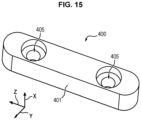
figure 15 représente une vue schématique en perspective d'une partie de la tête de soudage suivant des modes de réalisation de l'invention. - La
figure 16 représente une vue schématique en perspective d'une partie de la tête de soudage suivant des modes de réalisation de l'invention. - La
figure 17 représente une vue schématique en perspective coupée verticalement d'une partie de la tête de soudage suivant des modes de réalisation de l'invention. - La
figure 18 représente un exemple de profil de pièces pouvant être soudées par la tête et le procédé suivant l'invention. - La
figure 19 représente un exemple de soudures pouvant être effectuées sur des pièces par la tête et le procédé suivant l'invention. - La
figure 20 représente un exemple d'organigramme du procédé suivant un mode de réalisation de l'invention. - La
figure 21 représente un exemple d'organigramme du procédé suivant un mode de réalisation de l'invention. - La
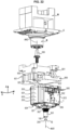
figure 22 représente une vue schématique en perspective éclatée de la tête de soudage montée sur une machine. - La
figure 23 représente une vue schématique en perspective de la tête de soudage montée sur une machine.
- There
figure 1 represents a schematic perspective view of a friction stir weld which can be carried out by the head and the method according to embodiments of the invention. - There
figure 2 represents a schematic perspective view of a welding tool, which may or may not have a retractable pin, and which may be mounted under the welding head according to embodiments of the invention. - There
Figure 3 represents a schematic perspective view of a welding head according to embodiments of the invention. - There
Figure 4 represents a schematic exploded perspective view of a retractable welding tool that can be mounted under the welding head according to embodiments of the invention. - There
figure 5 represents a schematic vertical sectional view of a welding head according to embodiments of the invention in a low position of the central pin. - There
Figure 6 represents a schematic vertical sectional view of a welding head according to embodiments of the invention in a high and retracted position of the central pin. - There
Figure 7 represents a schematic top view of the interior of a welding head according to embodiments of the invention. - There
figure 8 represents a schematic vertical sectional view of a welding head according to embodiments of the invention in an intermediate position of the central pin. - There
Figure 9 represents a schematic perspective view of a part of the welding head according to embodiments of the invention - There
Figure 10 represents a schematic exploded perspective view of a part of the welding head according to embodiments of the invention. - There
Figure 11 represents a schematic view in vertical section of a part of the welding head according to embodiments of the invention in the low position of the central pin. - There
Figure 12 represents a schematic view in vertical section of a part of the welding head according to embodiments of the invention in the high position of the central pin. - There
Figure 13 represents a schematic view in vertical section of a part of the welding head according to embodiments of the invention in the low position of the central pin. - There
Figure 14 represents a schematic view in vertical section of a part of the welding head according to embodiments of the invention in the high position of the central pin. - There
Figure 15 represents a schematic perspective view of a part of the welding head according to embodiments of the invention. - There
Figure 16 represents a schematic perspective view of a part of the welding head according to embodiments of the invention. - There
Figure 17 represents a schematic perspective view cut vertically of a part of the welding head according to embodiments of the invention. - There
Figure 18 represents an example of a profile of parts that can be welded by the head and the method according to the invention. - There
Figure 19 represents an example of welds that can be carried out on parts by the head and the method according to the invention. - There
Figure 20 represents an example of a flowchart of the process according to one embodiment of the invention. - There
Figure 21 represents an example of a flowchart of the process according to one embodiment of the invention. - There
Figure 22 represents a schematic exploded perspective view of the welding head mounted on a machine. - There
Figure 23 shows a schematic perspective view of the welding head mounted on a machine.
Aux
Sur la tête 1 peut être monté un outil O de soudage par friction malaxage. Cet outil O de soudage par friction malaxage comporte un épaulement périphérique 100 et un pion central 200 tournant et rétractable, qui est entouré par l'épaulement périphérique 100 autour d'un premier axe AX1 de rotation et qui est apte à faire saillie par rapport à l'épaulement périphérique 100 le long du premier axe AX1 de rotation. L'épaulement périphérique 100 est séparé du pion central 200, c'est-à-dire que l'épaulement périphérique 100 n'est pas d'une seule pièce avec le pion central 200. L'épaulement périphérique 100 comporte une surface inférieure 101 de soudage transversale au premier axe AX1 de rotation, tandis que le pion central 200 s'étend suivant le premier axe AX1 de rotation. Aux
Ainsi que représenté aux
Ainsi que représenté aux
Aux
Suivant un mode de réalisation de l'invention, l'arbre primaire rotatif 302 d'entraînement est monté par un palier 322 de support de rotation ou roulement (par exemple un roulement à billes) sur une partie inférieure d'un carter 321 du bâti 300. De ce carter 321 dépassent vers le bas la pièce 301 de fixation d'épaulement, l'épaulement périphérique 100 et le pion central 200 lorsqu'il dépasse de l'épaulement périphérique 100.According to one embodiment of the invention, the primary
Ainsi que représenté aux
Des modes de réalisation de ce premier dispositif 310 de transmission de rotation sont décrits ci-dessous, ainsi que représenté aux
Suivant un mode de réalisation de l'invention, le premier axe AX1 de rotation, l'arbre central rotatif 201 et l'arbre primaire rotatif 302 sont décalés d'une distance non nulle (par exemple suivant la direction horizontale transversale X aux
Suivant un mode de réalisation de l'invention, le premier dispositif 310 de transmission de rotation comporte un arbre secondaire 311 relié à et solidaire en rotation de la pièce 350 d'interface extérieure autour du deuxième axe AX2 de rotation. Une première poulie 312 est fixée à l'arbre secondaire 311 autour du deuxième axe AX2 de rotation, une deuxième poulie 313 est fixée à l'arbre primaire rotatif 302 autour du premier axe AX1 de rotation et une courroie 314 de transmission de rotation est disposée autour de la première poulie 312 et autour la deuxième poulie 313. La courroie 314 permet de transmettre la rotation de la pièce 350 d'interface extérieure autour du deuxième axe AX2 de rotation à l'arbre primaire rotatif 302 autour du premier axe AX1 de rotation. Dans d'autres modes de réalisation non représentés, le premier dispositif 310 de transmission de rotation peut être à engrenage ou autre entre la pièce 350 d'interface extérieure et l'arbre primaire rotatif 302.According to one embodiment of the invention, the first
Suivant un mode de réalisation de l'invention, l'arbre secondaire 311 est relié à la pièce 350 d'interface extérieure par l'intermédiaire d'un accouplement 315 à griffes. Cela permet notamment d'absorber des vibrations engendrées par la soudure ou de compenser les éventuels désalignements avec la broche de la machine M.According to one embodiment of the invention, the
Ainsi que représenté aux
Le procédé de soudure par friction malaxage des pièces P1, P2 à l'aide de la tête 1 de soudage montée sur la machine M comporte les étapes décrites ci-dessous en référence aux
On fixe initialement la pièce 350 d'interface extérieure de la tête 1 à la broche rotative B de la machine M, lors de l'étape initiale E0.The
Après l'étape initiale E0, on commande lors de l'étape E1 par un dispositif de contrôle du moteur 250 (par exemple interface homme-machine) la sortie ou la rentrée du pion central 200 hors de l'épaulement périphérique 100 jusqu'à la position basse.After the initial step E0, during step E1 the exit or reentry of the
Après l'étape initiale E0, on commande lors de l'étape E2 par un dispositif de contrôle de la machine M (par exemple interface homme-machine) la rotation de la broche B de la machine M pour provoquer la rotation du pion central 200 et de l'épaulement périphérique 100 autour du premier axe AX1 de rotation.After the initial step E0, during step E2 the rotation of the spindle B of the machine M is controlled by a control device of the machine M (for example man-machine interface) to cause the rotation of the
Après l'étape E1 ou E2, on abaisse lors de l'étape E3 par le dispositif de contrôle de la machine M la tête 1 par exemple vers la pièce P1 et/ou P2, pour abaisser l'épaulement périphérique 100 et le pion central 200 faisant saillie hors de l'épaulement périphérique 100, qui tournent tous les deux autour du premier axe AX1 de rotation, contre la pièce P1 et/ou P2.After step E1 or E2, during step E3 the
Après l'étape E3, on commande lors de l'étape E4 par le dispositif de contrôle du moteur 250 la translation du pion central 200 par rapport à l'épaulement périphérique 100 pour que l'extrémité inférieure 202 du pion central 200 soit rapprochée ou éloignée par rapport à l'épaulement périphérique 100, pendant que d'une part l'épaulement périphérique 100 qui se trouve en appui contre les pièces P1, P2, et d'autre part le pion central 200 tournent tous les deux autour du premier axe AX1 de rotation.After step E3, during step E4, the translation of the
Après l'étape E4, on éloigne lors de l'étape E5 la tête 1 par rapport aux pièces P1, P2.After step E4, during step E5 the
Suivant un mode de réalisation de l'invention, représenté à la
Suivant un mode de réalisation de l'invention, représenté à la
Ainsi, pour effectuer une soudure par friction malaxage, on commande par un dispositif de contrôle du moteur 250 la sortie de l'extrémité inférieure 202 du pion central 200 hors de l'épaulement périphérique 100 vers le bas jusqu'à une position intermédiaire ou jusqu'à la position basse et on l'y maintient dans cette position, où l'extrémité inférieure 202 du pion central 200 est saillante vers le bas hors de l'épaulement périphérique 100 (étape E1). On fait tourner par le dispositif de contrôle de la machine M la broche B de celle-ci pour provoquer la rotation de la pièce 350 d'interface extérieure autour du deuxième axe AX2 de rotation et, par l'intermédiaire du premier dispositif 310 de transmission, la rotation de l'arbre primaire rotatif 302 autour du premier axe AX1 de rotation, et donc la rotation de la pièce 301 de fixation de l'épaulement 100 et par ce fait la rotation du pion central 200 et la rotation de l'épaulement périphérique 100 autour du premier axe AX1 de rotation (étape E2). Puis, on abaisse par le dispositif de contrôle de la machine M la tête 1 vers les pièces P1 et P2, pour abaisser la surface inférieure 101 de l'épaulement périphérique 100 et le pion central 200 saillant vers le bas hors de cet l'épaulement périphérique 100, qui tournent tous les deux autour du premier axe AX1 de rotation, contre par exemple la pièce P1 et/ou P2, et on déplace la tête 1 par rapport aux pièces P1 et P2 pour effectuer la ligne SFSW de soudure le long de la ligne de joint LJ selon la
Le fait que l'on puisse régler différentes hauteurs de dépassement de l'extrémité inférieure 202 du pion central 200 vers le bas sous la surface inférieure 101 de l'épaulement périphérique 100 dans les positions intermédiaires et la position basse (étape E4) permet également de souder différentes épaisseurs des pièces P1 et P2, ainsi que représenté par exemple à la
Le fait que l'on puisse régler différentes hauteurs H de dépassement de l'extrémité inférieure 202 du pion central 200 vers le bas sous la surface inférieure 101 de l'épaulement périphérique 100 dans les positions intermédiaires et la position basse (étape E4) permet également de modifier au cours du déplacement horizontal D de l'outil O contre les pièces P1 et P2 le long de la ligne de joint LJ la hauteur H de dépassement de l'extrémité inférieure 202 du pion central 200 vers le bas sous la surface inférieure 101 de l'épaulement périphérique 100 dans les positions intermédiaires et la position basse à la
Bien entendu, le deuxième dispositif 210 d'entraînement peut translater l'arbre central rotatif 201 le long du premier axe AX1 de rotation à partir du moteur 250 également en l'absence de rotation de l'arbre central rotatif 201, de la pièce 301 de fixation d'épaulement, de l'épaulement périphérique 100 et du pion central 200 autour du premier axe AX1 de rotation.Of course, the
On décrit ci-dessous en référence aux
Suivant un mode de réalisation de l'invention, le bâti 300 peut comporter un boîtier extérieur 500 (rigide) comportant la paroi supérieure 323, d'autres parois extérieures latérales 501, 502, 503, 504, fixées à la paroi supérieure 323, et une paroi inférieure 505. Dans le boîtier extérieur 500 se trouvent les différentes parties de la tête 1. L'arbre primaire rotatif 302, la pièce 301 de fixation d'épaulement, le pion central 200 et l'épaulement périphérique 100 dépassent du boîtier extérieur 500, à savoir de la paroi inférieure 505. Le pion central 200 dépasse de la surface inférieure 101 de l'épaulement périphérique 100 dans les positions intermédiaires et dans la position basse. Les parois 323, 501, 502, 503, 504, 505 peuvent être rigides et/ou partiellement planes et/ou entièrement planes.According to one embodiment of the invention, the
Dans la position de montage de la tête 1 de soudage sur la machine M, la surface supérieure 323 de la tête 1 de soudage et/ou le boîtier 500 est fixée à un adaptateur 600 (ou pièce 600 d'adaptation ou pièce 600 de fixation). L'adaptateur 600 est fixé au châssis C de la machine M. La tête 1 de soudage et/ou la surface supérieure 323 et/ou le boîtier 500 peut comporter des organes 506 de fixation ou d'assemblage, pour fixer ou assembler la tête 1 de soudage et/ou la surface supérieure 323 et/ou le boîtier 500 à l'adaptateur 600. L'adaptateur 600 peut comporter des organes 601 de fixation ou d'assemblage, pour fixer ou assembler l'adaptateur 600 au châssis C de la machine M. Les organes 506 de fixation peuvent être ou comprendre par exemple des vis 506 ou des boulons 506, ou des tiges 506, ou autres. Les organes 601 de fixation peuvent être ou comprendre par exemple des vis 601 ou des boulons 601, ou des tiges 601, ou autres. L'adaptateur 600 comporte un trou traversant 602 dans lequel passe la pièce 350 d'interface extérieure dans la position de montage de la tête 1 de soudage sur la machine M. Dans la position de montage de la tête 1 de soudage sur la machine M, la pièce 350 d'interface extérieure est fixée à la broche B de la machine M, par exemple par un accouplement mécanique. Dans la position de montage de la tête 1 de soudage sur la machine M, l'adaptateur 600 se trouve entre le châssis C et la surface supérieure 323.In the mounting position of the
Suivant un autre mode de réalisation de l'invention, l'adaptateur 600 est d'une seule pièce avec le boîtier 500 de la tête 1 de soudage et est inséparable du boîtier 500 de la tête 1 de soudage. Dans ce cas, les organes 506 de fixation en sont pas prévus.According to another embodiment of the invention, the
On décrit ci-dessous des modes de réalisation du deuxième dispositif 210 d'entraînement en translation de l'arbre central 201 en référence aux
Suivant un mode de réalisation de l'invention, le moteur 250 comporte un arbre tertiaire 251 rotatif autour d'un troisième axe AX3 de rotation. Le deuxième dispositif 210 d'entraînement en translation comporte un arbre intermédiaire 221, qui est déporté au-dessus de l'arbre central 201 et qui est coaxial au premier axe AX1 de rotation. Un mécanisme 220 de transmission de rotation de l'arbre tertiaire 251 rotatif du moteur 250 autour de son troisième axe AX3 de rotation à l'arbre intermédiaire 221 autour du premier axe AX1 de rotation est prévu dans le deuxième dispositif 210 d'entraînement en translation. En outre, un mécanisme 230 de transformation de la rotation de l'arbre intermédiaire 221 autour du premier axe AX1 de rotation en une translation de l'arbre central 201 le long du premier axe AX1 de rotation est prévu dans le deuxième dispositif 210 d'entraînement en translation.According to one embodiment of the invention, the
On décrit ci-dessous des modes de réalisation de ces mécanismes 220 et 230.Embodiments of these
Suivant un mode de réalisation de l'invention, aux
Suivant un mode de réalisation de l'invention, aux
Suivant un mode de réalisation de l'invention, aux
Suivant un autre mode de réalisation de l'invention, aux
Suivant un mode de réalisation de l'invention, aux
Suivant un mode de réalisation de l'invention, aux
Suivant un mode de réalisation de l'invention, aux
Suivant un mode de réalisation de l'invention, aux
Suivant un autre mode de réalisation de l'invention, non représenté aux figures, le premier organe 231 est taraudé et est un écrou 231 fixé à l'arbre intermédiaire 221 ou formant la partie d'extrémité inférieure de l'arbre intermédiaire 221, le deuxième organe 232 est fileté et est une vis 232, l'écrou 231 étant vissé autour de la vis 232.According to another embodiment of the invention, not shown in the figures, the
Suivant un mode de réalisation de l'invention, aux
Suivant un mode de réalisation de l'invention, aux
Suivant un mode de réalisation de l'invention, aux
Suivant un mode de réalisation de l'invention, aux
Suivant un mode de réalisation de l'invention, aux
Ainsi, lorsque le moteur 250 fait tourner l'arbre tertiaire 251 dans un premier sens prescrit autour du troisième axe AX3 de rotation, l'arbre intermédiaire 221 et le premier organe 231 de la partie inférieure de l'arbre 221 tournent dans un deuxième sens prescrit autour du premier axe AX1 de rotation, ce qui fait remonter, du fait du blocage en rotation du deuxième organe 232 par l'élément 233, ce deuxième organe 232 et le manchon 234 le long du premier axe AX1 de rotation, par exemple pour passer de la position des
A l'inverse, lorsque le moteur 250 fait tourner l'arbre tertiaire 251 dans un troisième sens prescrit inverse du premier sens prescrit autour du troisième axe AX3 de rotation, l'arbre intermédiaire 221 et le premier organe 231 de la partie inférieure de l'arbre 221 tournent dans un quatrième sens prescrit inverse du deuxième sens prescrit autour du premier axe AX1 de rotation, ce qui fait descendre, du fait du blocage en rotation du deuxième organe 232 par l'élément 233, ce deuxième organe 232 et le manchon 234 le long du premier axe AX1 de rotation, par exemple pour passer de la position des
Suivant un mode de réalisation de l'invention, aux
Suivant un mode de réalisation de l'invention, le palier 322 de support de rotation ou roulement (par exemple un roulement à billes) est monté autour du bas de la surface extérieure de la paroi cylindrique circulaire 305 de l'arbre primaire rotatif 302 autour du premier axe AX1 de rotation et dans le carter 321. Un autre palier 324 de support de rotation ou roulement (par exemple un roulement à billes) peut être monté autour du haut de la surface extérieure de la paroi cylindrique circulaire 305 de l'arbre primaire rotatif 302 autour du premier axe AX1 de rotation et dans une partie intérieure et supérieure 325 du carter 321 du bâti 300.According to one embodiment of the invention, the rotation support bearing 322 or bearing (for example a ball bearing) is mounted around the bottom of the outer surface of the circular
Suivant un mode de réalisation de l'invention, aux
Suivant un mode de réalisation de l'invention, aux
Suivant un mode de réalisation de l'invention, aux
Suivant un mode de réalisation de l'invention, aux
Suivant un autre mode de réalisation de l'invention, non représenté aux figures, la deuxième partie 402 d'accouplement est saillante sur la surface intérieure 403 de la pièce 301 de fixation d'épaulement transversalement au premier axe AX1 de rotation, et la première partie 401 d'accouplement est une rainure, qui s'étend sur l'arbre central rotatif 201 le long du premier axe AX1 de rotation. La deuxième partie 402 d'accouplement peut être formée par une clavette 401 saillante, fixée sur la surface intérieure 403 de la pièce 301 de fixation d'épaulement par une ou plusieurs vis 404 traversant un ou plusieurs trous 405 de la clavette 401 et vissés dans un ou plusieurs taraudages transversaux 203 de la pièce 301 de fixation d'épaulement.According to another embodiment of the invention, not shown in the figures, the
Dans des modes de réalisation de l'invention, le système 400 d'accouplement mécanique peut comporter une partie mâle 401 d'accouplement et une partie femelle 402 d'accouplement. La partie mâle 401 d'accouplement peut se trouver sur la pièce 301 ou inversement sur l'arbre central rotatif 201. La partie femelle 402 d'accouplement peut se trouver sur la pièce 301 ou inversement sur l'arbre central rotatif 201.In embodiments of the invention, the
Suivant un mode de réalisation de l'invention, aux
Suivant un mode de réalisation de l'invention, aux
Ainsi, lorsque la tête 1, par l'intermédiaire de l'abaissement du châssis C, est abaissée vers les pièces P1, P2 à souder, les vibrations remontant de l'outil O vers la pièce 301 de fixation d'épaulement, vers l'arbre central 201 suivant le premier axe AX1 de rotation sont amorties par le ou les élément élastique 326 et ne sont donc pas ou très peu transmises à la broche B de la machine M. Les efforts axiaux exercés sur l'outil O sont transmis au palier constitué par exemple par le roulement 322, puis à l'élément élastique 326, lequel absorbe ces efforts axiaux, qui sont alors reportés sur le bâti 300 et donc le châssis C de la machine M, sans passer par la broche B de cette machine M. On protège ainsi la broche B de la machine M vis-à-vis des efforts axiaux de forgeage, et également des efforts transversaux de forgeage pouvant être dus au déplacement de l'outil O transversalement à l'axe AX1 selon le déplacement D. La broche B de la machine M n'a donc à fournir à la tête 1 que le couple de rotation pour souder. La tête 1 procure ainsi une sécurité vis-à-vis de la broche B et dispose d'un contrôle d'effort, c'est-à-dire un système permettant de garder un effort de forge dans un intervalle largement acceptable pour la qualité des soudures malgré les défauts géométriques des pièces, par exemples causés par des surfaces brutes. Cela permet de réaliser des soudures répétables. L'interface homme-machine permet de contrôler les différents paramètres de la machine M et permet d'avertir l'opérateur s'il y a un incident, de faire du contrôle qualité des soudures en enregistrant les paramètres de soudure. L'interface homme-machine et l'automatisation du pion rétractable 200 peuvent s'effectuer via un ordinateur et un automate autonomes et indépendants de la machine-outil à commande numérique, rendant le système complètement universel.Thus, when the
Suivant un mode de réalisation de l'invention, aux
Suivant un mode de réalisation de l'invention, aux
Bien entendu, les modes de réalisation, caractéristiques, possibilités et exemples décrits ci-dessus peuvent être combinés l'un avec l'autre ou être sélectionnés indépendamment l'un de l'autre.Of course, the embodiments, features, possibilities and examples described above can be combined with each other or selected independently of each other.
Claims (17)
- A friction stir welding head (1), intended to be secured to a machine (M) for carrying out friction stir welding using a tool comprising a peripheral shoulder (100) and a central pin (200), which is surrounded by the peripheral shoulder (100) about a first axis of rotation (AX1) and which is able to protrude from the peripheral shoulder (100),the head (1) comprising a frame (300), intended to be secured to a chassis (C) of the machine (M),the head (1) comprising a central rotary shaft (201) to which the central pin (200) is intended to be secured, a shoulder securing part (301), which is located about the central shaft (201) and to which the peripheral shoulder (100) is intended to be secured,the head (1) further comprising a primary rotary shaft (302) for driving in rotation both the shoulder securing part (301) and the central rotary shaft (201) about the first axis of rotation (AX1),the central rotary shaft (201) and the shoulder securing part (301) having a coupling device (400) for coupling them to each other, so that the central rotary shaft (201) is integral in rotation with the shoulder securing part (301) about the first axis of rotation (AX1) and so that the central rotary shaft (201) is free in translation with respect to the shoulder securing part (301) along the first axis of rotation (AX1),the head (1) comprising a motor (250) and a second translational drive device (210) for driving in translation the central rotary shaft (201) along the first axis of rotation (AX1) from the motor (250) during the rotation of the central rotary shaft (201) and of the shoulder securing part (301) about the first axis of rotation (AX1), between at least a low position of the central rotary shaft (201), in which the central pin (200) protrudes from the peripheral shoulder (100) along the first axis of rotation (AX1) and a high position of the central rotary shaft (201), in which the central pin (200) does not protrude from the peripheral shoulder (100) along the first axis of rotation (AX1),characterized in that the head (1) comprises an external interface part (350) intended to be secured to a rotary spindle (B) of the machine (M) and a first rotation transmission device (310) for transmitting the rotation of the external interface part (350) to the primary rotary shaft (302) about the first axis of rotation (AX1), the external interface part (350) projecting from an upper surface (323) of the frame (300).
- The head according to claim 1, wherein the first axis of rotation (AX1), the central rotary shaft (201) and the primary rotary shaft (302) are offset and parallel with respect to a second axis of rotation (AX2) of the external interface part (350).
- The head according to any one of the preceding claims, wherein the first rotation transmission device (310) comprises a secondary shaft (311) integral in rotation with the external interface part (350) about the second axis of rotation (AX2), a first pulley (312) secured about the secondary shaft (311), a second pulley (313) secured about the primary rotary shaft (302) and a rotation transmission belt (314) between the first pulley (312) and the second pulley (313) to transmit the rotation of the external interface part (350) about the second axis of rotation (AX2) to the primary rotary shaft (302) about the first axis of rotation (AX1).
- The head according to any one of the preceding claims, wherein the motor (250) comprises a tertiary rotary shaft (251) about a third axis of rotation (AX3),
the second translational drive device (210) comprises an intermediate shaft (221) which is coaxial and offset with respect to the central rotary shaft (201), a rotation transmission mechanism (220) for transmitting the rotation of the tertiary rotary shaft (251) about the third axis of rotation (AX3) to the intermediate shaft (221) about the first axis of rotation (AX1) and a rotation transformation mechanism (230) for transforming the rotation of the intermediate shaft (221) about the first axis of rotation (AX1) in translation of the central rotary shaft (201) along the first axis of rotation (AX1). - The head according to claim 4, wherein the tertiary shaft (251) of the motor (250) is rotatable about the third axis of rotation (AX3) offset and transverse with respect to the first axis of rotation (AX1),
the rotation transmission mechanism (220) comprises an angle transmission mechanism (225) of the tertiary rotary shaft (251) about the third axis of rotation (AX3) to the intermediate shaft (221) about the first axis of rotation (AX1). - The head according to claim 5, wherein the angle transmission mechanism (225) of the tertiary rotary shaft (251) comprises at least a first worm screw (222) integral in rotation with the tertiary shaft (251) and at least a second toothed wheel (223) integral in rotation about the intermediate shaft (221), the second toothed wheel (223) meshing with the first worm screw (222).
- The head according to any one of claims 4 to 6, wherein the rotation transformation mechanism (230) comprises a first threaded member (231), which is secured to or formed by the intermediate shaft (221), a second tapped member (232), which is integral in translation with the central shaft (201) along the first axis of rotation (AX1), and a rotation blocking element (233) for blocking rotation of the second tapped member (232), the first threaded member (232) cooperating by a screw connection with the second tapped member (232) about the first axis of rotation (AX1),
the rotation blocking element (233) being secured to an internal plate (226), about which the intermediate shaft (221) is rotatably mounted, the internal plate (226) being mounted in the frame (300). - The head according to claim 7, wherein the first threaded member (231) is a screw (231) secured to or formed by the intermediate shaft (221), the second tapped member (232) is a nut (232) screwed about the screw (231).
- The head according to any one of claims 4 to 6, wherein the rotation transformation mechanism (230) comprises a first tapped member (231), which is secured to or formed by the intermediate shaft (221), a second threaded member (232), which is integral in translation with the central shaft (201) along the first axis of rotation (AX1), and a rotation blocking element (233) for blocking rotation of the first tapped member (231), the first tapped member (231) cooperating by a screw connection with the second threaded member (232) about the first axis of rotation (AX1),the blocking element (233) being secured to an internal plate (226), about which the intermediate shaft (221) is rotatably mounted, the internal plate (226) being mounted in the frame (300),the first tapped member (231) is a nut secured to the intermediate shaft (221), the second threaded member (232) is a screw, the nut being screwed about the screw.
- The head according to any one of claims 7 to 9, wherein the rotation transformation mechanism (230) comprises a sleeve (234), which comprises a first side (2341) secured about the second member (232) and a second side (2342) in which a rotation support bearing (235) of the central shaft (201) about the first axis of rotation (AX1) is secured.
- The head according to claim 10, wherein the rotation support bearing (235) is a bearing assembly (235), comprising at least a first bearing portion (2351) secured in the second side (2342) of the sleeve (234) and at least a second bearing portion (2352) secured to the central shaft (201) and rotatable with respect to the first bearing portion (2351).
- The head according to claim 10 or 11, wherein the sleeve (234) is inserted into an internal cavity (303) of the primary rotary shaft (302) and is movable in translation along the first axis of rotation (AX1) in the internal cavity (303).
- The head according to any one of the preceding claims, wherein the coupling device (400) comprises a first coupling portion (401) secured to the central rotary shaft (201) and a second coupling portion (402) secured in the shoulder securing part (301), the first coupling portion (401) cooperating by a sliding connection with the second coupling portion (402) along the first axis of rotation (AX1) and being integral in rotation with the second coupling portion (402).
- The head according to claim 13, wherein the first coupling portion (401) is protruding on the central rotary shaft (201) transversely to the first axis of rotation (AX1), the second coupling portion (402) is a groove (402), which extends over an internal surface (403) of the shoulder securing part (301) along the first axis of rotation (AX1) and in which the first coupling portion (401) is movable in translation along the first axis of rotation (AX1) while being blocked in rotation about the first axis of rotation (AX1).
- The head according to any one of the preceding claims, wherein in the high position the central pin (200) is retracted above a lower surface (101) of the peripheral shoulder (100).
- The head according to any one of the preceding claims, wherein the shoulder securing part (301) and the peripheral shoulder (100) are in one piece.
- A method for friction-stir welding pieces (P1, P2), characterized by the following steps:mounting the frame (300) of the welding head (1) according to any one of the preceding claims on a machine (M),the external interface part (350) of the head (1) projecting from an upper surface (323) of the frame (300) of the welding head (1) and being secured to a rotary spindle (B) of the machine (M),commanding (E1) by a motor control device for controlling the motor (250) the central pin (200) to move out of the peripheral shoulder (100) up to the low position,commanding (E2) by a machine control device for controlling the machine (M) the rotary spindle (B) of the machine (M) to rotate to cause the peripheral shoulder (100) and the central pin (200) to rotate about the first axis of rotation (AX1),lowering (E3) by the machine control device the welding head (1) towards the pieces (P1, P2), in order to lower the peripheral shoulder (100) and the central pin (200) protruding out of the peripheral shoulder (100), which both rotate about the first axis of rotation (AX1),against the pieces (P1, P2),commanding (E4) by the motor control device the central pin (200) to translate with respect to the peripheral shoulder (100) so that a lower end (202) of the central pin (200) is moved closer or away with respect to the peripheral shoulder (100), while on the one hand the peripheral shoulder (100), which is in contact against the pieces (P1, P2), and on the other hand the central pin (200), both rotate about the first axis of rotation (AX1),moving the welding head (1) away (E5) with respect to the pieces (P1, P2).
Applications Claiming Priority (1)
| Application Number | Priority Date | Filing Date | Title |
|---|---|---|---|
| FR2103957A FR3121855B1 (en) | 2021-04-16 | 2021-04-16 | Friction stir welding head and method using same |
Publications (3)
| Publication Number | Publication Date |
|---|---|
| EP4074452A1 EP4074452A1 (en) | 2022-10-19 |
| EP4074452C0 EP4074452C0 (en) | 2023-11-15 |
| EP4074452B1 true EP4074452B1 (en) | 2023-11-15 |
Family
ID=76375211
Family Applications (1)
| Application Number | Title | Priority Date | Filing Date |
|---|---|---|---|
| EP22166634.0A Active EP4074452B1 (en) | 2021-04-16 | 2022-04-05 | Head for friction stir welding and method using such welding head |
Country Status (4)
| Country | Link |
|---|---|
| US (1) | US20220331897A1 (en) |
| EP (1) | EP4074452B1 (en) |
| CA (1) | CA3156030A1 (en) |
| FR (1) | FR3121855B1 (en) |
Families Citing this family (2)
| Publication number | Priority date | Publication date | Assignee | Title |
|---|---|---|---|---|
| CN112453681B (en) * | 2020-10-22 | 2022-06-14 | 北京工业大学 | Retractable friction stir welding electric spindle |
| CN117001137B (en) * | 2023-09-22 | 2023-12-15 | 江苏攀森智能科技有限公司 | Split quick-change cutter for friction stir welding of motor casing and replacement method |
Family Cites Families (28)
| Publication number | Priority date | Publication date | Assignee | Title |
|---|---|---|---|---|
| US6484924B1 (en) * | 2001-08-14 | 2002-11-26 | The Boeing Company | Method and apparatus for backing up a friction stir weld joint |
| US6732900B2 (en) * | 2002-04-02 | 2004-05-11 | Mts Systems Corporation | Friction stir welding spindle with axially displaceable spindle shaft |
| JP2004136331A (en) * | 2002-10-18 | 2004-05-13 | Hitachi Ltd | Equipment and method for friction stir welding |
| JP2005211971A (en) * | 2004-01-30 | 2005-08-11 | Mitsubishi Motors Corp | Friction stir welding apparatus |
| US8052030B2 (en) * | 2005-01-24 | 2011-11-08 | The Boeing Company | Apparatus for friction stir welding using spindle-in-spindle |
| US7641096B2 (en) * | 2005-01-24 | 2010-01-05 | The Boeing Company | Friction stir welding apparatus |
| JP4754256B2 (en) * | 2005-04-19 | 2011-08-24 | 住友軽金属工業株式会社 | Rotating tool for friction stir spot welding and friction stir spot joining method using the same |
| JP4628218B2 (en) * | 2005-08-22 | 2011-02-09 | Obara株式会社 | Friction stir spot welding equipment |
| JP4853864B2 (en) * | 2006-02-20 | 2012-01-11 | Obara Group株式会社 | Cleaning method of FSW joint tool |
| US7641739B2 (en) * | 2006-06-13 | 2010-01-05 | The Boeing Company | Friction stir welding tool cleaning method |
| US9511461B2 (en) * | 2006-10-05 | 2016-12-06 | The Boeing Company | Independent axis ancillary device |
| JP4325875B2 (en) * | 2006-11-06 | 2009-09-02 | 株式会社日立製作所 | Friction stir welding tool and friction stir welding apparatus |
| JP5287866B2 (en) * | 2008-02-08 | 2013-09-11 | 富士電機機器制御株式会社 | Electric contact manufacturing method and electric contact manufacturing apparatus |
| US20090294511A1 (en) * | 2008-05-30 | 2009-12-03 | Vanderbilt University | Lateral position detection for friction stir systems |
| US20100072261A1 (en) * | 2008-09-25 | 2010-03-25 | Marcio Fernando Cruz | Friction stir welding spindle downforce and other control techniques, systems and methods |
| US8261959B2 (en) * | 2008-09-25 | 2012-09-11 | Embraer S.A. | Friction stir welding spindle downforce and other control techniques, systems and methods |
| JP5463736B2 (en) * | 2009-06-02 | 2014-04-09 | Obara Group株式会社 | Hollow drive unit incorporating a piezoelectric load cell |
| JP5631162B2 (en) * | 2010-11-16 | 2014-11-26 | カルソニックカンセイ株式会社 | Friction stir welding method |
| US9387551B2 (en) * | 2012-09-06 | 2016-07-12 | Apple Inc. | Method, system, and computer program product for simulating friction stir welding |
| DE102014010058B4 (en) * | 2014-07-07 | 2016-01-28 | Grenzebach Maschinenbau Gmbh | Method and device for fast and safe tool change in the process of friction stir welding and a computer program for performing the method |
| ES2651500T3 (en) * | 2015-03-18 | 2018-01-26 | Helmholtz-Zentrum Geesthacht Zentrum für Material- und Küstenforschung GmbH | Apparatus for welding by friction-stirring with a projection comprising first and second through holes |
| DE102016007585B3 (en) * | 2016-06-21 | 2017-11-02 | Grenzebach Maschinenbau Gmbh | Device and method for welding two joining partners by means of friction stir welding through, or by, no contamination of the joining partners by welding residues occurs, as well as a computer program for performing the method |
| JP6637181B2 (en) * | 2016-08-10 | 2020-01-29 | 株式会社東芝 | Friction stir welding device, processing position setting device, and measuring device |
| US20180056436A1 (en) * | 2016-08-26 | 2018-03-01 | The Boeing Company | Systems, methods, and devices for exit hole repair associated with welding operations |
| AU2018359514C1 (en) * | 2017-10-31 | 2021-05-27 | MELD Manufacturing Corporation | Solid-state additive manufacturing system and material compositions and structures |
| AT522421A1 (en) * | 2019-02-25 | 2020-10-15 | Stirtec Gmbh | Method for joining or machining and device for this |
| EP3965025A1 (en) * | 2020-08-21 | 2022-03-09 | Tata Consultancy Services Limited | Method and system for multi-sensor fusion using transform learning |
| JP6892544B1 (en) * | 2020-10-28 | 2021-06-23 | 株式会社日立パワーソリューションズ | Friction stir welding device and friction stir welding method |
-
2021
- 2021-04-16 FR FR2103957A patent/FR3121855B1/en active Active
-
2022
- 2022-04-05 EP EP22166634.0A patent/EP4074452B1/en active Active
- 2022-04-14 CA CA3156030A patent/CA3156030A1/en active Pending
- 2022-04-14 US US17/720,690 patent/US20220331897A1/en active Pending
Also Published As
| Publication number | Publication date |
|---|---|
| CA3156030A1 (en) | 2022-10-16 |
| FR3121855B1 (en) | 2024-04-19 |
| EP4074452C0 (en) | 2023-11-15 |
| US20220331897A1 (en) | 2022-10-20 |
| FR3121855A1 (en) | 2022-10-21 |
| EP4074452A1 (en) | 2022-10-19 |
Similar Documents
| Publication | Publication Date | Title |
|---|---|---|
| EP4074452B1 (en) | Head for friction stir welding and method using such welding head | |
| EP0227694B1 (en) | Control device for displacing an element, particularly a seat or parts of a seat of a motor vehicle with respect to a frame | |
| EP2440482B1 (en) | Width-adjusting device for conveyor corridor(s) | |
| EP3145790B1 (en) | Steering column mechanism adjustable in depth with a retractable stopper | |
| EP3389913B1 (en) | Friction stir welding head having coupling members and at least one resilient element | |
| EP0194217B1 (en) | Industrial robots of the spherical type | |
| FR2593728A1 (en) | PUNCHER WITH BALANCED DRIVE | |
| EP0588713B1 (en) | Machine for grinding, facing and polishing for automatic tool changing and corresponding device | |
| FR2951392A1 (en) | LASER WELDING INSTALLATION | |
| EP1493529B1 (en) | Assembling machine with a turret carrying a plurality of assembling tools | |
| FR2929145A1 (en) | DOCKING STATION | |
| EP2790894B1 (en) | Automated device for plasma surface preparation of a thermoplastic part | |
| FR3121622A1 (en) | HEAD FOR GRIPPING AND PUNCHING A PART ALLOWING ITS DRIVE IN ROTATION FOR ITS MACHINING | |
| FR2892960A1 (en) | Machine tool e.g. vertical machining center, for e.g. machining long and broad piece, has machining unit relatively movable along three axial directions, and protection mechanisms provided at level of front and rear openings | |
| WO2002053305A1 (en) | Device and method for making connections that cross over exhaust devices | |
| EP3983170A1 (en) | Spindle with piezoelectric actuators | |
| FR2888142A1 (en) | Machine tool for machining wide and long workpiece, comprises spindle attached with tool, and machining unit by which spindle is supported to be movable in axes directions and being movable in arrangement direction of machining areas | |
| EP3633236B1 (en) | Power-steering reduction gear housing comprising a notch on one side of an intermediate drilling hole | |
| FR2711085A1 (en) | Automatic machine for moving a work tool, particularly a machine tool, in space. | |
| EP4084922B1 (en) | Electrospindle with integrated feed with automatic tool holder change | |
| FR3074709B1 (en) | HAND TOOL FOR RECTIFYING THE DIAMETER OF A POSITIONING ELEMENT SUCH AS A CENTERING PIONE | |
| EP0554629A1 (en) | Honing machine with expansible tool | |
| EP3086902B1 (en) | Rotary tool for removing material of a plastic part | |
| WO2024074798A2 (en) | System for working a workpiece comprising a machine tool and corresponding working method | |
| CH312313A (en) | Tube cutting machine. |
Legal Events
| Date | Code | Title | Description |
|---|---|---|---|
| PUAI | Public reference made under article 153(3) epc to a published international application that has entered the european phase |
Free format text: ORIGINAL CODE: 0009012 |
|
| STAA | Information on the status of an ep patent application or granted ep patent |
Free format text: STATUS: THE APPLICATION HAS BEEN PUBLISHED |
|
| AK | Designated contracting states |
Kind code of ref document: A1 Designated state(s): AL AT BE BG CH CY CZ DE DK EE ES FI FR GB GR HR HU IE IS IT LI LT LU LV MC MK MT NL NO PL PT RO RS SE SI SK SM TR |
|
| STAA | Information on the status of an ep patent application or granted ep patent |
Free format text: STATUS: REQUEST FOR EXAMINATION WAS MADE |
|
| 17P | Request for examination filed |
Effective date: 20230118 |
|
| RBV | Designated contracting states (corrected) |
Designated state(s): AL AT BE BG CH CY CZ DE DK EE ES FI FR GB GR HR HU IE IS IT LI LT LU LV MC MK MT NL NO PL PT RO RS SE SI SK SM TR |
|
| GRAP | Despatch of communication of intention to grant a patent |
Free format text: ORIGINAL CODE: EPIDOSNIGR1 |
|
| STAA | Information on the status of an ep patent application or granted ep patent |
Free format text: STATUS: GRANT OF PATENT IS INTENDED |
|
| RIC1 | Information provided on ipc code assigned before grant |
Ipc: B23K 20/12 20060101AFI20230614BHEP |
|
| INTG | Intention to grant announced |
Effective date: 20230706 |
|
| GRAS | Grant fee paid |
Free format text: ORIGINAL CODE: EPIDOSNIGR3 |
|
| GRAA | (expected) grant |
Free format text: ORIGINAL CODE: 0009210 |
|
| STAA | Information on the status of an ep patent application or granted ep patent |
Free format text: STATUS: THE PATENT HAS BEEN GRANTED |
|
| AK | Designated contracting states |
Kind code of ref document: B1 Designated state(s): AL AT BE BG CH CY CZ DE DK EE ES FI FR GB GR HR HU IE IS IT LI LT LU LV MC MK MT NL NO PL PT RO RS SE SI SK SM TR |
|
| REG | Reference to a national code |
Ref country code: CH Ref legal event code: EP Ref country code: GB Ref legal event code: FG4D Free format text: NOT ENGLISH |
|
| REG | Reference to a national code |
Ref country code: DE Ref legal event code: R096 Ref document number: 602022000978 Country of ref document: DE |
|
| REG | Reference to a national code |
Ref country code: IE Ref legal event code: FG4D Free format text: LANGUAGE OF EP DOCUMENT: FRENCH |
|
| U01 | Request for unitary effect filed |
Effective date: 20231214 |
|
| U07 | Unitary effect registered |
Designated state(s): AT BE BG DE DK EE FI FR IT LT LU LV MT NL PT SE SI Effective date: 20231221 |
|
| PG25 | Lapsed in a contracting state [announced via postgrant information from national office to epo] |
Ref country code: GR Free format text: LAPSE BECAUSE OF FAILURE TO SUBMIT A TRANSLATION OF THE DESCRIPTION OR TO PAY THE FEE WITHIN THE PRESCRIBED TIME-LIMIT Effective date: 20240216 |
|
| PG25 | Lapsed in a contracting state [announced via postgrant information from national office to epo] |
Ref country code: IS Free format text: LAPSE BECAUSE OF FAILURE TO SUBMIT A TRANSLATION OF THE DESCRIPTION OR TO PAY THE FEE WITHIN THE PRESCRIBED TIME-LIMIT Effective date: 20240315 |
|
| U20 | Renewal fee paid [unitary effect] |
Year of fee payment: 3 Effective date: 20240314 |