JP2005211971A - Friction stir welding equipment - Google Patents
Friction stir welding equipment Download PDFInfo
- Publication number
- JP2005211971A JP2005211971A JP2004024438A JP2004024438A JP2005211971A JP 2005211971 A JP2005211971 A JP 2005211971A JP 2004024438 A JP2004024438 A JP 2004024438A JP 2004024438 A JP2004024438 A JP 2004024438A JP 2005211971 A JP2005211971 A JP 2005211971A
- Authority
- JP
- Japan
- Prior art keywords
- welded
- tool
- inner member
- main body
- members
- Prior art date
- Legal status (The legal status is an assumption and is not a legal conclusion. Google has not performed a legal analysis and makes no representation as to the accuracy of the status listed.)
- Pending
Links
Images
Landscapes
- Pressure Welding/Diffusion-Bonding (AREA)
Abstract
【課題】本発明は、被溶接部材の強度低下を防ぐことができる摩擦撹拌接合装置を提供する。
【解決手段】摩擦撹拌接合装置10は、第1,2被溶接部材11,12に押圧されて回転する接合ツール50を備えている。接合ツール50は、接合ツール回転機構60によって回転駆動されるツール本体51と、ツール本体51の内部にその軸線方向に移動可能に挿通された内側部材52とを備えている。内側部材52は、ツール本体51の第1被溶接部材11と対向する先端面51aから第1,2被溶接部材11,12に向かって突出する第1の方向Aに移動可能で、かつ第1の方向Aとは反対の第2の方向Bに移動可能である。
【選択図】 図3The present invention provides a friction stir welding apparatus capable of preventing a decrease in strength of a member to be welded.
A friction stir welding apparatus includes a welding tool that is pressed and rotated by first and second welded members. The joining tool 50 includes a tool body 51 that is rotationally driven by the joining tool rotation mechanism 60, and an inner member 52 that is inserted into the tool body 51 so as to be movable in the axial direction thereof. The inner member 52 is movable in a first direction A that protrudes toward the first and second welded members 11 and 12 from the distal end surface 51a of the tool main body 51 that faces the first welded member 11. It is possible to move in the second direction B opposite to the direction A.
[Selection] Figure 3
Description
本発明は、例えば2枚の金属板同士を互いに結合する作業等に用いる摩擦撹拌接合装置に関する。 The present invention relates to a friction stir welding apparatus used for, for example, an operation of joining two metal plates together.
アルミニウムなどの熱伝導性がよい金属からなる被溶接部材同士を溶接する場合、抵抗発熱によって被溶接部材を溶融させて接合する抵抗溶接では、エネルギーを多く必要とする。このため、少ないエネルギーで熱伝導性がよい被溶接部材同士を溶接する装置として、摩擦熱を利用して部材同士を接合するスポット接合装置(摩擦撹拌接合装置)が提案されている(例えば、特許文献1参照。)。 When welding members to be welded made of a metal having good thermal conductivity such as aluminum, resistance welding in which the members to be welded are melted and joined by resistance heat generation requires a lot of energy. For this reason, a spot welding device (friction stir welding device) that joins members using frictional heat has been proposed as a device for welding members to be welded with low energy and good thermal conductivity (for example, a patent) Reference 1).
このスポット接合装置は、複数重ねられた被接合部材(被溶接部材)に押圧された状態で回転し、被接合部材との間で摩擦熱を生じる接合ツールを備えている。接合ツールは、ショルダー部(ツール本体)と、ショルダー部の先端に突出するピン部を一体に有する形状である。 This spot bonding apparatus includes a bonding tool that rotates while being pressed by a plurality of bonded members to be bonded (welded members) and generates frictional heat with the bonded members. The joining tool has a shape integrally including a shoulder portion (tool main body) and a pin portion protruding from the tip of the shoulder portion.
ピン部は、被溶接部材との間の回転する摩擦部の圧力を高め、高い摩擦熱を得るために設けられており、摩擦熱で被溶接部材が溶融したときに、該溶融金属内に挿入される。被接合部材同士は、前記ピン部の回転によって生じる摩擦熱によってピン部付近が溶融されるとともに、溶融金属が流動したのち固化することにより互いに一体化して接合される。
しかし、前記のスポット接合装置では、接合後にピン部を被接合部材から引き抜くと、被接合部材のナゲットには、それまでピンが嵌入していた凹部が残ってしまう。この凹部の低部の肉厚は、周囲に比べて薄くなる。それゆえ、凹部は、被溶接部材に加わる荷重が大きいときなどに亀裂などの欠陥が生じる原因になり、溶接後の被接合部材の強度が低下するおそれがある。 However, in the spot bonding apparatus, when the pin portion is pulled out from the member to be bonded after the bonding, the concave portion into which the pin has been inserted remains in the nugget of the member to be bonded. The thickness of the lower part of the recess is thinner than the surrounding area. Therefore, the concave portion causes a defect such as a crack when the load applied to the member to be welded is large, and the strength of the member to be joined after welding may be reduced.
したがって、本発明の目的は、被溶接部材の強度低下を防ぐことができる摩擦撹拌接合装置を提供することにある。 Therefore, the objective of this invention is providing the friction stir welding apparatus which can prevent the strength reduction of a to-be-welded member.
前記目的を達成するために、本発明の接合ツールは、駆動手段によって回転駆動されるツール本体と、該ツール本体の内部にその軸線方向に移動可能に挿通される内側部材とを備えている。内側部材は、ツール本体の被溶接部材と対向する先端面から被溶接部材に向かって突出する第1の方向と該第1の方向とは反対の第2の方向に移動可能である。 In order to achieve the above object, a joining tool of the present invention includes a tool main body that is rotationally driven by a driving means, and an inner member that is inserted into the tool main body so as to be movable in the axial direction thereof. The inner member is movable in a first direction that protrudes from the tip surface facing the member to be welded of the tool main body toward the member to be welded and a second direction opposite to the first direction.
前記内側部材は、回転しながら被溶接部材に挿入されて被溶接部材を溶融させた後に、ツール本体の先端面が溶融金属に接したまま内側部材が被溶接部材から離れる第2の方向に移動する。このとき、ツール本体は、被溶接部材に当接されて回転している状態が維持されている。このため、被溶接部材中の溶融金属は、ツール本端との摩擦熱によって溶融状態が維持されるので内側部材が退避した跡には、溶融金属の一部が流入する。 The inner member is inserted into the member to be welded while rotating and melts the member to be welded, and then moves in the second direction in which the inner member moves away from the member to be welded while the tip surface of the tool body is in contact with the molten metal. To do. At this time, the tool main body is kept in contact with the member to be welded and rotating. For this reason, since the molten metal in the member to be welded is maintained in a molten state by frictional heat with the tool main end, a part of the molten metal flows into the trace where the inner member is retracted.
この発明の好ましい形態では、前記内側部材は、ツール本体の先端面と略面一になる位置まで移動可能である。この構成によれば、内側部材が被溶接部材を撹拌した後にツール本体と面一になるまで移動することにより、被溶接部材に形成されるナゲットは、ツール本体と内側部材とによって略平坦に均される。 In a preferred form of the invention, the inner member is movable to a position that is substantially flush with the tip surface of the tool body. According to this configuration, the nugget formed on the member to be welded is approximately flattened by the tool body and the inner member by moving the inner member until it is flush with the tool body after stirring the member to be welded. Is done.
請求項1に記載した発明によれば、被溶接部材に形成されるナゲットに、内側部材が嵌入していたことによる凹部の形成が抑えられるので、溶接された後の被溶接部材の強度が低下することが抑制される。 According to the first aspect of the present invention, since the formation of the recess due to the inner member being fitted into the nugget formed on the member to be welded is suppressed, the strength of the member to be welded after welding is reduced. Is suppressed.
請求項2に記載した発明によれば、請求項1に記載の発明の効果に加えて、より一層強度低下を防いで被溶接部材同士を接合することができる。 According to the invention described in claim 2, in addition to the effect of the invention described in claim 1, the members to be welded can be joined to each other while further preventing the strength from being lowered.
本発明の第1の実施形態に係る摩擦撹拌接合装置について、図1から図6を参照して説明する。摩擦撹拌接合装置10は、複数の被溶接部材、例えば第1被溶接部材11と第2被溶接部材12とを接合する装置である。第1,2被溶接部材11,12は、それぞれ例えば熱伝導性が良いアルミニウム合金から成形されている。
A friction stir welding apparatus according to a first embodiment of the present invention will be described with reference to FIGS. The friction
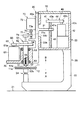
摩擦撹拌接合装置10は、フレーム20と、フレーム20に対して例えば上下方向に移動可能な移動部30と、移動部30を移動可能とする移動機構40とを備えている。
The friction
フレーム20は、図1に示すように、例えば床面21などに固定される基部22と、基部22の上端部に設けられて移動機構40を収容する収容部23とを備えている。基部22は、例えば略L字形状であって、その先端に第1,2被溶接部材11,12が上下方向に重ねられて固定される受け部24が設けられている。この明細書では、被溶接部材のうち、上側に配置される部材を第1被溶接部材11と呼び、下側に配置される部材を第2被溶接部材12と呼ぶ。収容部23の縦壁23aには、水平方向に貫通する孔23bが形成されている。
As shown in FIG. 1, the
移動部30は、例えば収容部23の縦壁23aに沿って上下方向に移動可能に係合されている。また、移動部30は、収容部23の孔23bから収容部23の内部に突出する突出部31を有している。なお、孔23bは、移動部30の突出部31よりも上下方向に大きく形成されており、突出部31は、孔23b内で上下方向に移動可能である。
The moving
移動機構40は、例えばボールねじ41と、ボールねじ41を回転させる第1モータ42とを備えている。ボールねじ41のねじ軸43は、収容部23の内部で上下方向に組み付けられている。ボールねじ41のナット41aは、移動部30の突出部31の先端に組み付けられており、ねじ軸43に螺合している。
The
ねじ軸43の上端部には、例えばプーリ43aが取り付けられている。第1モータ42の回転軸42aの上端には、例えばプーリ42bが取り付けられている。プーリ43aとプーリ42bとは、ベルト44を介して連結されている。これにより、第1モータ42の回転がベルト44を介してねじ軸43に伝達されるようになっている。これにより、移動部30は、第1モータ42が回転することにより、ガイド30aに沿って上下方向に移動可能となる。
For example, a
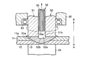
また、摩擦撹拌接合装置10は、接合ツール50と、接合ツール回転機構60と、移動機構70などを備えている。接合ツール50は、第1,2被溶接部材11,12に押圧された状態で回転し、第1,2被溶接部材11,12との間で摩擦熱を発生する部位であって、ツール本体51と内側部材52とを備えている。ツール本体51と内側部材52とは、それぞれ第1,2被溶接部材11,12よりも融点が高い素材で形成されており、例えば鉄を主体とする金属で形成されている。
The friction
ツール本体51は、例えば上下方向に延びる略円筒形状であって、その下端が第1被溶接部材11の上面11aと対向するように、かつ軸線が上下方向に沿うように、転がり軸受53を介して移動部30に固定されている。すなわち、ツール本体51は、その軸線回りに回転自由に移動部30に固定されている。
The tool
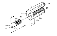
ツール本体51は、第1被溶接部材11と対向する先端面51aが移動部30の下面32よりも下方に突出して固定されている。ツール本体51の内周面51bには、図2に示すように、軸線方向に沿って複数の歯溝(スプライン溝)54が形成されている。
The tool
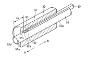
内側部材52は、図2に示すように、例えば上下方向に延びてツール本体51の内周孔に挿通される円柱形状であって、側面52aにツール本体51の歯溝54と係合する複数の歯溝(スプライン溝)55が形成されるスプライン軸である。すなわち、内側部材52は、スプライン結合によってツール本体51と係合しており、ツール本体51に対して軸線方向に沿って相対的に移動可能であるとともに、ツール本体51と一体に回転することができる。
As shown in FIG. 2, the
つまり、内側部材52は、ツール本体51の先端面51aに対して、第1,2被溶接部材11,12に向かう第1の方向であるAと、第1の方向とは反対の第2の方向であるBに移動可能である。また、内側部材52は、図1に示すように、ツール本体51の上端よりもさらに上方に延びている。
That is, the
ツール本体51と内側部材52のそれぞれの歯溝54,55について詳しく説明すると、図2に示すように、内側部材52の第1被溶接部材11と対向する先端面52bから歯溝55の下端55aまでの距離は、所定距離L1である。この所定距離L1は、少なくとも内側部材52がツール本体51の先端面51aから突出する長さよりも長く形成されている。
The tooth grooves 54 and 55 of the tool
ツール本体51の先端面51aから歯溝54の下端54aまでの距離L2は、少なくともL1よりも長く形成されている。これにより、内側部材52は、先端面52bがツール本体51の先端面51aと面一なる位置まで移動することができる。
A distance L2 from the
接合ツール回転機構60は、ツール本体51を軸回りに回転させる機能を有している。このツール回転機構60は、図1に示すように、例えば第2モータ61とベルト62とプーリ63,64などを備えている。第2モータ61は、移動部30において例えば接合ツール50の近傍に固定されている。プーリ64は、例えばツール本体51の上端部に固定されている。プーリ63は、第2モータ61の回転軸61aに固定されている。プーリ64とプーリ63とは、ベルト62を介して連結されている。これにより、第2モータ61の回転がツール本体51に伝わるようになっている。
The joining
移動機構70は、ツール本体51に対して内側部材52を上下方向に移動する機能を有している。この移動機構70は、例えばボールねじ71と、ボールねじ71のねじ軸72を回転させる第3モータ73などを備えている。
The moving
第3モータ73は、例えば、第3モータ73の回転軸73aが内側部材52の軸線と略平行になるように移動部30の上部に固定されている。ねじ軸72の上端は、第3モータ73の回転軸73aの下端に固定されている。これにより、第3モータ73の回転がねじ軸72に伝えられる。
For example, the
ボールねじ71のナット71aは、例えば内側部材52の上端とねじ軸72とを連結する接合部74の内部に組み込まれており、ねじ軸72に螺合している。また、接合部74の内部には、例えば転がり軸受が組み込まれている。この転がり軸受に内側部材52の上端が取り付けられている。これにより、接合部74が、内側部材52と一体に回転することがなくなり、第3モータ73が稼働することによって内側部材52は、上下方向に移動する。
The
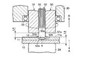
次に摩擦撹拌接合装置10の動作の一例を説明する。接合ツール50の初期状態(摩擦撹拌接合の開始時)においては、図3に示すように、例えば、内側部材52がツール本体51の先端面51aから突出している。
Next, an example of the operation of the friction
まず、第1,2被溶接部材11,12が上下方向に重ねられて受け部24に固定される。なお、ツール本体51の先端面51aから内側部材52の先端面52bまでの距離L3は、例えば第1,2被溶接部材11,12の厚みL4よりも小さく設定される。
First, the first and second welded
ついで、第2モータ61が稼働されて接合ツール50が回転するとともに、第1モータ42が稼働されて移動部30が下方(矢印Aで示す方向)に移動する。このため、まず、内側部材52が第1被溶接部材11に当接する。これにより、内側部材52と第1被溶接部材11との摩擦により、内側部材52の周囲の第1被溶接部材11が溶融する。
Next, the
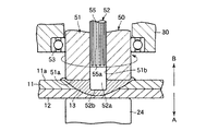
さらに移動部30が矢印A方向に移動すると、内側部材52は、摩擦熱によって第1,2被溶接部材11,12を溶融しながら第1,2被溶接部材11,12の内部に挿入される。図4に示すように、ツール本体51の先端面51aが第1被溶接部材11と当接すると、第1モータ42の稼働が停止されて、移動部30のA方向への移動が停止される。なお、ツール本体51の先端面51aは、第1被溶接部材11中に若干めり込んでもよい。
When the moving
この間も内側部材52およびツール本体51は、回転状態が維持されているため、内側部材52の周囲の溶融金属13は、内側部材52によって撹拌される。また、第1,2被溶接部材11,12は、ツール本体51の先端面51aとの摩擦によっても溶融する。
During this time, the
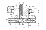
ツール本体51の先端面51aが第1被溶接部材11と当接して所定時間が経過すると、第3モータ73が稼働されて、図5に示すように、内側部材52が上方(矢印Bで示す第2の方向)に移動される。このとき、ツール本体51は、第1被溶接部材11に当接して回転状態が維持されるので、第1,2被溶接部材11,12の内部の溶融金属13は、摩擦熱によって溶融状態が維持されている。このため、第1,2被溶接部材11,12の内部において、内側部材52が移動した跡には、溶融金属13が流れ込む。
When a predetermined time elapses after the
なお、ツール本体51の先端面51aが第1被溶接部材11と当接してから第3モータ73が稼働されるまでの所定時間は、第1,2被溶接部材11,12の内部で溶融金属13が充分に塑性流動された時間に基づいて設定される。
The predetermined time from when the
ついで、図6に示すように、内側部材52の先端面52bがツール本体51の先端面51aと略面一になると第3モータ73の稼働が停止される。これにより、溶融金属13の表面13aは、ツール本体51と内側部材52との両先端面51a,52bとによって略平らに均される。
Next, as shown in FIG. 6, the operation of the
ついで、所定時間が経過すると第1モータ42が稼働され、移動部30が上方に移動する。このとき、第1,2被溶接部材11,12の溶融金属13は、接合ツール50と接触しなくなるので冷えて固まる。これにより、第1,2被溶接部材11,12は互いに接合される。なお、ツール本体51と内側部材52との両先端面51a,52bが略面一になってから第1モータ42が稼働されるまでの所定時間は、溶融金属13の表面13aが充分均されるのに必要な時間に基づいて設定されている。
Next, when a predetermined time elapses, the
このように構成された摩擦撹拌接合装置10では、接合ツール50は、第1,2被溶接部材11,12を溶融して撹拌した後、まず内側部材52だけがツール本体51に対して相対的に第2の方向Bに移動する。このとき、第1,2被溶接部材11,12の溶融金属13は、ツール本体51との摩擦熱により溶融状態が保たれるので、溶融金属13は、内側部材52の移動跡に流入する。
In the friction
すなわち、第1,2被溶接部材11,12に形成されるナゲットに、内側部材52が嵌入していたことによる凹部が形成されることが抑えられるので、接合された後の第1,2被溶接部材11,12の強度低下が抑えられる。
In other words, the nuggets formed on the first and second welded
また、内側部材52が、その先端面52bとツール本体51の先端面51aとが面一になるまで移動することにより、溶融金属13の表面13aがツール本体51および内側部材52の両先端面51a,52bによって略平らに均される。それゆえ、摩擦撹拌接合装置10は、より一層強度低下を防いで第1,2被溶接部材11,12を接合することができる。
Further, the
次に、本発明の第2の実施形態に係る摩擦撹拌接合装置10について図7を参照して説明する。なお、第1の実施形態と同様の構成については同一の符号を付して説明を省略する。
Next, a friction
図7は、ツール本体51と内側部材52との係合状態を示している。内側部材52にキー80が設けられている。ツール本体51の内周面51bには、キー80と係合するキー溝81がツール本体51の軸線方向に沿って形成されている。キー80は、内側部材52の側面52aに形成されたキー溝82に係合している。ツール本体51と内側部材52とは、キー80を用いて係合されている。内側部材52の先端面52bからキー溝82の下端82aまでの距離L5は、内側部材52の突出長さL3(図3に示す)よりも長く形成されている。
FIG. 7 shows an engaged state between the tool
このように構成された第2の実施形態に係る摩擦撹拌接合装置10は、第1の実施形態と同じ効果を得ることができる。なお、第1,2の実施形態では、被溶接部材として、第1被溶接部材11と第2被溶接部材12とを用いたが、これに限定されるものではなく、例えば3つの被溶接部材を溶接することもできる。
The friction
10…摩擦撹拌接合装置、11…第1被溶接部材(被溶接部材)、12…第2被溶接部材(被溶接部材)、50…接合ツール、51…ツール本体、51a…先端面、52…内側部材、A…第1の方向、B…第2の方向。
DESCRIPTION OF
Claims (2)
前記接合ツールは、
駆動手段によって回転駆動されるツール本体と、
該ツール本体の内部にその軸線方向に移動可能に挿通され、かつ前記ツール本体の前記被溶接部材と対向する先端面から前記被溶接部材に向かって突出する第1の方向と該第1の方向とは反対の第2の方向に移動可能な内側部材と
を具備したことを特徴とする摩擦撹拌接合装置。 A friction stir welding apparatus including a welding tool that is pressed and rotated by a member to be welded,
The joining tool is
A tool body that is rotationally driven by a driving means;
A first direction that is inserted into the tool body so as to be movable in the axial direction thereof, and protrudes from the tip end surface of the tool body facing the member to be welded toward the member to be welded, and the first direction. A friction stir welding apparatus, comprising: an inner member movable in a second direction opposite to the first member.
Priority Applications (1)
| Application Number | Priority Date | Filing Date | Title |
|---|---|---|---|
| JP2004024438A JP2005211971A (en) | 2004-01-30 | 2004-01-30 | Friction stir welding equipment |
Applications Claiming Priority (1)
| Application Number | Priority Date | Filing Date | Title |
|---|---|---|---|
| JP2004024438A JP2005211971A (en) | 2004-01-30 | 2004-01-30 | Friction stir welding equipment |
Publications (1)
| Publication Number | Publication Date |
|---|---|
| JP2005211971A true JP2005211971A (en) | 2005-08-11 |
Family
ID=34907121
Family Applications (1)
| Application Number | Title | Priority Date | Filing Date |
|---|---|---|---|
| JP2004024438A Pending JP2005211971A (en) | 2004-01-30 | 2004-01-30 | Friction stir welding equipment |
Country Status (1)
| Country | Link |
|---|---|
| JP (1) | JP2005211971A (en) |
Cited By (5)
| Publication number | Priority date | Publication date | Assignee | Title |
|---|---|---|---|---|
| JP2007054837A (en) * | 2005-08-22 | 2007-03-08 | Obara Corp | Friction stir spot welding equipment |
| JP2007216249A (en) * | 2006-02-15 | 2007-08-30 | Kawasaki Heavy Ind Ltd | Friction stir spot welding equipment |
| US7898138B2 (en) | 2006-12-06 | 2011-03-01 | Hitachi Industrial Equipment Systems Co., Ltd. | Rotary electric machine |
| JPWO2021241674A1 (en) * | 2020-05-29 | 2021-12-02 | ||
| EP4074452A1 (en) * | 2021-04-16 | 2022-10-19 | Stirweld | Head for friction stir welding and method using such welding head |
-
2004
- 2004-01-30 JP JP2004024438A patent/JP2005211971A/en active Pending
Cited By (11)
| Publication number | Priority date | Publication date | Assignee | Title |
|---|---|---|---|---|
| JP2007054837A (en) * | 2005-08-22 | 2007-03-08 | Obara Corp | Friction stir spot welding equipment |
| JP2007216249A (en) * | 2006-02-15 | 2007-08-30 | Kawasaki Heavy Ind Ltd | Friction stir spot welding equipment |
| US7898138B2 (en) | 2006-12-06 | 2011-03-01 | Hitachi Industrial Equipment Systems Co., Ltd. | Rotary electric machine |
| JPWO2021241674A1 (en) * | 2020-05-29 | 2021-12-02 | ||
| JP7489457B2 (en) | 2020-05-29 | 2024-05-23 | 川崎重工業株式会社 | Friction stir spot welding device and joint structure |
| JP2024100815A (en) * | 2020-05-29 | 2024-07-26 | 川崎重工業株式会社 | Friction stir spot welding device and joint structure |
| US12202066B2 (en) | 2020-05-29 | 2025-01-21 | Kawasaki Jukogyo Kabushiki Kaisha | Friction stir spot welding apparatus and joint structure |
| JP7739521B2 (en) | 2020-05-29 | 2025-09-16 | 川崎重工業株式会社 | Friction stir spot welding device and joint structure |
| EP4074452A1 (en) * | 2021-04-16 | 2022-10-19 | Stirweld | Head for friction stir welding and method using such welding head |
| FR3121855A1 (en) * | 2021-04-16 | 2022-10-21 | Stirweld | Friction stir welding head and method using the same |
| US12023753B2 (en) | 2021-04-16 | 2024-07-02 | Stirweld | Friction stir welding head and method using the same |
Similar Documents
| Publication | Publication Date | Title |
|---|---|---|
| US6832713B2 (en) | Spot joining method and spot joining device | |
| US20080029581A1 (en) | Method of joining together dissimilar metal members | |
| US20040118900A1 (en) | Precessing rivet and method for friction stir riveting | |
| JP3400409B2 (en) | Joining method and joining device | |
| JP2004106037A (en) | How to join metal materials | |
| JP4937386B2 (en) | Dissimilar metal member joining method | |
| JP4602796B2 (en) | Dissimilar metal member joining method | |
| JP2007007729A (en) | Friction stir welding equipment | |
| US6702535B1 (en) | Rivet with sliding cap and extendable stirrer for friction stir riveting | |
| JP3505508B2 (en) | Friction stir welding equipment | |
| JP7353329B2 (en) | Welding device and method for friction stir welding and resistance welding | |
| JP4479416B2 (en) | Friction spot welding method and apparatus | |
| EP1884308B1 (en) | Method of friction stir welding together dissimilar metal members with a double acting rotary tool for filling of the hole created by the probe | |
| US6883699B2 (en) | Rivet with sliding cap for friction stir riveting | |
| JP2003181654A (en) | Friction stir welding device | |
| JP2005211971A (en) | Friction stir welding equipment | |
| US20060081679A1 (en) | Friction stir spot joining device | |
| JP3401499B2 (en) | Welding equipment using friction stir | |
| JP3463671B2 (en) | Joining method and apparatus using friction stirring | |
| JP2002144053A (en) | Friction stir tool, joining method using the same, and method for removing fine voids on casting surface | |
| JP4703958B2 (en) | Friction stir welding equipment | |
| JP4331038B2 (en) | Friction stir spot welding device | |
| US20070040007A1 (en) | Friction stir spot joining device | |
| JP4671523B2 (en) | Process management method and process management apparatus using friction stirring | |
| JP2002263865A (en) | Friction stir welding |
Legal Events
| Date | Code | Title | Description |
|---|---|---|---|
| A621 | Written request for application examination |
Effective date: 20060324 Free format text: JAPANESE INTERMEDIATE CODE: A621 |
|
| A977 | Report on retrieval |
Free format text: JAPANESE INTERMEDIATE CODE: A971007 Effective date: 20080919 |
|
| A131 | Notification of reasons for refusal |
Effective date: 20080930 Free format text: JAPANESE INTERMEDIATE CODE: A131 |
|
| A02 | Decision of refusal |
Effective date: 20090217 Free format text: JAPANESE INTERMEDIATE CODE: A02 |