EP4074436A1 - Joining material, production method for joining material, and joined body - Google Patents
Joining material, production method for joining material, and joined body Download PDFInfo
- Publication number
- EP4074436A1 EP4074436A1 EP20876598.2A EP20876598A EP4074436A1 EP 4074436 A1 EP4074436 A1 EP 4074436A1 EP 20876598 A EP20876598 A EP 20876598A EP 4074436 A1 EP4074436 A1 EP 4074436A1
- Authority
- EP
- European Patent Office
- Prior art keywords
- joining material
- joining
- sintered body
- less
- silver
- Prior art date
- Legal status (The legal status is an assumption and is not a legal conclusion. Google has not performed a legal analysis and makes no representation as to the accuracy of the status listed.)
- Granted
Links
Images


Classifications
-
- B—PERFORMING OPERATIONS; TRANSPORTING
- B22—CASTING; POWDER METALLURGY
- B22F—WORKING METALLIC POWDER; MANUFACTURE OF ARTICLES FROM METALLIC POWDER; MAKING METALLIC POWDER; APPARATUS OR DEVICES SPECIALLY ADAPTED FOR METALLIC POWDER
- B22F3/00—Manufacture of workpieces or articles from metallic powder characterised by the manner of compacting or sintering; Apparatus specially adapted therefor ; Presses and furnaces
- B22F3/10—Sintering only
-
- B—PERFORMING OPERATIONS; TRANSPORTING
- B22—CASTING; POWDER METALLURGY
- B22F—WORKING METALLIC POWDER; MANUFACTURE OF ARTICLES FROM METALLIC POWDER; MAKING METALLIC POWDER; APPARATUS OR DEVICES SPECIALLY ADAPTED FOR METALLIC POWDER
- B22F1/00—Metallic powder; Treatment of metallic powder, e.g. to facilitate working or to improve properties
- B22F1/05—Metallic powder characterised by the size or surface area of the particles
- B22F1/052—Metallic powder characterised by the size or surface area of the particles characterised by a mixture of particles of different sizes or by the particle size distribution
-
- B—PERFORMING OPERATIONS; TRANSPORTING
- B22—CASTING; POWDER METALLURGY
- B22F—WORKING METALLIC POWDER; MANUFACTURE OF ARTICLES FROM METALLIC POWDER; MAKING METALLIC POWDER; APPARATUS OR DEVICES SPECIALLY ADAPTED FOR METALLIC POWDER
- B22F1/00—Metallic powder; Treatment of metallic powder, e.g. to facilitate working or to improve properties
-
- B—PERFORMING OPERATIONS; TRANSPORTING
- B22—CASTING; POWDER METALLURGY
- B22F—WORKING METALLIC POWDER; MANUFACTURE OF ARTICLES FROM METALLIC POWDER; MAKING METALLIC POWDER; APPARATUS OR DEVICES SPECIALLY ADAPTED FOR METALLIC POWDER
- B22F1/00—Metallic powder; Treatment of metallic powder, e.g. to facilitate working or to improve properties
- B22F1/05—Metallic powder characterised by the size or surface area of the particles
- B22F1/054—Nanosized particles
- B22F1/0545—Dispersions or suspensions of nanosized particles
-
- B—PERFORMING OPERATIONS; TRANSPORTING
- B22—CASTING; POWDER METALLURGY
- B22F—WORKING METALLIC POWDER; MANUFACTURE OF ARTICLES FROM METALLIC POWDER; MAKING METALLIC POWDER; APPARATUS OR DEVICES SPECIALLY ADAPTED FOR METALLIC POWDER
- B22F1/00—Metallic powder; Treatment of metallic powder, e.g. to facilitate working or to improve properties
- B22F1/06—Metallic powder characterised by the shape of the particles
-
- B—PERFORMING OPERATIONS; TRANSPORTING
- B22—CASTING; POWDER METALLURGY
- B22F—WORKING METALLIC POWDER; MANUFACTURE OF ARTICLES FROM METALLIC POWDER; MAKING METALLIC POWDER; APPARATUS OR DEVICES SPECIALLY ADAPTED FOR METALLIC POWDER
- B22F1/00—Metallic powder; Treatment of metallic powder, e.g. to facilitate working or to improve properties
- B22F1/10—Metallic powder containing lubricating or binding agents; Metallic powder containing organic material
- B22F1/107—Metallic powder containing lubricating or binding agents; Metallic powder containing organic material containing organic material comprising solvents, e.g. for slip casting
-
- B—PERFORMING OPERATIONS; TRANSPORTING
- B22—CASTING; POWDER METALLURGY
- B22F—WORKING METALLIC POWDER; MANUFACTURE OF ARTICLES FROM METALLIC POWDER; MAKING METALLIC POWDER; APPARATUS OR DEVICES SPECIALLY ADAPTED FOR METALLIC POWDER
- B22F3/00—Manufacture of workpieces or articles from metallic powder characterised by the manner of compacting or sintering; Apparatus specially adapted therefor ; Presses and furnaces
- B22F3/10—Sintering only
- B22F3/11—Making porous workpieces or articles
-
- B—PERFORMING OPERATIONS; TRANSPORTING
- B22—CASTING; POWDER METALLURGY
- B22F—WORKING METALLIC POWDER; MANUFACTURE OF ARTICLES FROM METALLIC POWDER; MAKING METALLIC POWDER; APPARATUS OR DEVICES SPECIALLY ADAPTED FOR METALLIC POWDER
- B22F3/00—Manufacture of workpieces or articles from metallic powder characterised by the manner of compacting or sintering; Apparatus specially adapted therefor ; Presses and furnaces
- B22F3/10—Sintering only
- B22F3/11—Making porous workpieces or articles
- B22F3/1103—Making porous workpieces or articles with particular physical characteristics
-
- B—PERFORMING OPERATIONS; TRANSPORTING
- B22—CASTING; POWDER METALLURGY
- B22F—WORKING METALLIC POWDER; MANUFACTURE OF ARTICLES FROM METALLIC POWDER; MAKING METALLIC POWDER; APPARATUS OR DEVICES SPECIALLY ADAPTED FOR METALLIC POWDER
- B22F3/00—Manufacture of workpieces or articles from metallic powder characterised by the manner of compacting or sintering; Apparatus specially adapted therefor ; Presses and furnaces
- B22F3/12—Both compacting and sintering
- B22F3/14—Both compacting and sintering simultaneously
-
- B—PERFORMING OPERATIONS; TRANSPORTING
- B22—CASTING; POWDER METALLURGY
- B22F—WORKING METALLIC POWDER; MANUFACTURE OF ARTICLES FROM METALLIC POWDER; MAKING METALLIC POWDER; APPARATUS OR DEVICES SPECIALLY ADAPTED FOR METALLIC POWDER
- B22F3/00—Manufacture of workpieces or articles from metallic powder characterised by the manner of compacting or sintering; Apparatus specially adapted therefor ; Presses and furnaces
- B22F3/24—After-treatment of workpieces or articles
-
- B—PERFORMING OPERATIONS; TRANSPORTING
- B22—CASTING; POWDER METALLURGY
- B22F—WORKING METALLIC POWDER; MANUFACTURE OF ARTICLES FROM METALLIC POWDER; MAKING METALLIC POWDER; APPARATUS OR DEVICES SPECIALLY ADAPTED FOR METALLIC POWDER
- B22F3/00—Manufacture of workpieces or articles from metallic powder characterised by the manner of compacting or sintering; Apparatus specially adapted therefor ; Presses and furnaces
- B22F3/24—After-treatment of workpieces or articles
- B22F3/26—Impregnating
-
- B—PERFORMING OPERATIONS; TRANSPORTING
- B22—CASTING; POWDER METALLURGY
- B22F—WORKING METALLIC POWDER; MANUFACTURE OF ARTICLES FROM METALLIC POWDER; MAKING METALLIC POWDER; APPARATUS OR DEVICES SPECIALLY ADAPTED FOR METALLIC POWDER
- B22F7/00—Manufacture of composite layers, workpieces, or articles, comprising metallic powder, by sintering the powder, with or without compacting wherein at least one part is obtained by sintering or compression
- B22F7/002—Manufacture of composite layers, workpieces, or articles, comprising metallic powder, by sintering the powder, with or without compacting wherein at least one part is obtained by sintering or compression of porous nature
-
- B—PERFORMING OPERATIONS; TRANSPORTING
- B22—CASTING; POWDER METALLURGY
- B22F—WORKING METALLIC POWDER; MANUFACTURE OF ARTICLES FROM METALLIC POWDER; MAKING METALLIC POWDER; APPARATUS OR DEVICES SPECIALLY ADAPTED FOR METALLIC POWDER
- B22F7/00—Manufacture of composite layers, workpieces, or articles, comprising metallic powder, by sintering the powder, with or without compacting wherein at least one part is obtained by sintering or compression
- B22F7/002—Manufacture of composite layers, workpieces, or articles, comprising metallic powder, by sintering the powder, with or without compacting wherein at least one part is obtained by sintering or compression of porous nature
- B22F7/004—Manufacture of composite layers, workpieces, or articles, comprising metallic powder, by sintering the powder, with or without compacting wherein at least one part is obtained by sintering or compression of porous nature comprising at least one non-porous part
-
- B—PERFORMING OPERATIONS; TRANSPORTING
- B22—CASTING; POWDER METALLURGY
- B22F—WORKING METALLIC POWDER; MANUFACTURE OF ARTICLES FROM METALLIC POWDER; MAKING METALLIC POWDER; APPARATUS OR DEVICES SPECIALLY ADAPTED FOR METALLIC POWDER
- B22F7/00—Manufacture of composite layers, workpieces, or articles, comprising metallic powder, by sintering the powder, with or without compacting wherein at least one part is obtained by sintering or compression
- B22F7/008—Manufacture of composite layers, workpieces, or articles, comprising metallic powder, by sintering the powder, with or without compacting wherein at least one part is obtained by sintering or compression characterised by the composition
-
- B—PERFORMING OPERATIONS; TRANSPORTING
- B22—CASTING; POWDER METALLURGY
- B22F—WORKING METALLIC POWDER; MANUFACTURE OF ARTICLES FROM METALLIC POWDER; MAKING METALLIC POWDER; APPARATUS OR DEVICES SPECIALLY ADAPTED FOR METALLIC POWDER
- B22F7/00—Manufacture of composite layers, workpieces, or articles, comprising metallic powder, by sintering the powder, with or without compacting wherein at least one part is obtained by sintering or compression
- B22F7/02—Manufacture of composite layers, workpieces, or articles, comprising metallic powder, by sintering the powder, with or without compacting wherein at least one part is obtained by sintering or compression of composite layers
-
- B—PERFORMING OPERATIONS; TRANSPORTING
- B22—CASTING; POWDER METALLURGY
- B22F—WORKING METALLIC POWDER; MANUFACTURE OF ARTICLES FROM METALLIC POWDER; MAKING METALLIC POWDER; APPARATUS OR DEVICES SPECIALLY ADAPTED FOR METALLIC POWDER
- B22F7/00—Manufacture of composite layers, workpieces, or articles, comprising metallic powder, by sintering the powder, with or without compacting wherein at least one part is obtained by sintering or compression
- B22F7/02—Manufacture of composite layers, workpieces, or articles, comprising metallic powder, by sintering the powder, with or without compacting wherein at least one part is obtained by sintering or compression of composite layers
- B22F7/04—Manufacture of composite layers, workpieces, or articles, comprising metallic powder, by sintering the powder, with or without compacting wherein at least one part is obtained by sintering or compression of composite layers with one or more layers not made from powder, e.g. made from solid metal
-
- B—PERFORMING OPERATIONS; TRANSPORTING
- B22—CASTING; POWDER METALLURGY
- B22F—WORKING METALLIC POWDER; MANUFACTURE OF ARTICLES FROM METALLIC POWDER; MAKING METALLIC POWDER; APPARATUS OR DEVICES SPECIALLY ADAPTED FOR METALLIC POWDER
- B22F7/00—Manufacture of composite layers, workpieces, or articles, comprising metallic powder, by sintering the powder, with or without compacting wherein at least one part is obtained by sintering or compression
- B22F7/06—Manufacture of composite layers, workpieces, or articles, comprising metallic powder, by sintering the powder, with or without compacting wherein at least one part is obtained by sintering or compression of composite workpieces or articles from parts, e.g. to form tipped tools
- B22F7/062—Manufacture of composite layers, workpieces, or articles, comprising metallic powder, by sintering the powder, with or without compacting wherein at least one part is obtained by sintering or compression of composite workpieces or articles from parts, e.g. to form tipped tools involving the connection or repairing of preformed parts
-
- B—PERFORMING OPERATIONS; TRANSPORTING
- B22—CASTING; POWDER METALLURGY
- B22F—WORKING METALLIC POWDER; MANUFACTURE OF ARTICLES FROM METALLIC POWDER; MAKING METALLIC POWDER; APPARATUS OR DEVICES SPECIALLY ADAPTED FOR METALLIC POWDER
- B22F7/00—Manufacture of composite layers, workpieces, or articles, comprising metallic powder, by sintering the powder, with or without compacting wherein at least one part is obtained by sintering or compression
- B22F7/06—Manufacture of composite layers, workpieces, or articles, comprising metallic powder, by sintering the powder, with or without compacting wherein at least one part is obtained by sintering or compression of composite workpieces or articles from parts, e.g. to form tipped tools
- B22F7/08—Manufacture of composite layers, workpieces, or articles, comprising metallic powder, by sintering the powder, with or without compacting wherein at least one part is obtained by sintering or compression of composite workpieces or articles from parts, e.g. to form tipped tools with one or more parts not made from powder
-
- B—PERFORMING OPERATIONS; TRANSPORTING
- B23—MACHINE TOOLS; METAL-WORKING NOT OTHERWISE PROVIDED FOR
- B23K—SOLDERING OR UNSOLDERING; WELDING; CLADDING OR PLATING BY SOLDERING OR WELDING; CUTTING BY APPLYING HEAT LOCALLY, e.g. FLAME CUTTING; WORKING BY LASER BEAM
- B23K35/00—Rods, electrodes, materials, or media, for use in soldering, welding, or cutting
- B23K35/22—Rods, electrodes, materials, or media, for use in soldering, welding, or cutting characterised by the composition or nature of the material
- B23K35/24—Selection of soldering or welding materials proper
- B23K35/30—Selection of soldering or welding materials proper with the principal constituent melting at less than 1550°C
- B23K35/3006—Ag as the principal constituent
-
- C—CHEMISTRY; METALLURGY
- C22—METALLURGY; FERROUS OR NON-FERROUS ALLOYS; TREATMENT OF ALLOYS OR NON-FERROUS METALS
- C22C—ALLOYS
- C22C1/00—Making non-ferrous alloys
- C22C1/04—Making non-ferrous alloys by powder metallurgy
- C22C1/0466—Alloys based on noble metals
-
- H—ELECTRICITY
- H10—SEMICONDUCTOR DEVICES; ELECTRIC SOLID-STATE DEVICES NOT OTHERWISE PROVIDED FOR
- H10W—GENERIC PACKAGES, INTERCONNECTIONS, CONNECTORS OR OTHER CONSTRUCTIONAL DETAILS OF DEVICES COVERED BY CLASS H10
- H10W95/00—Packaging processes not covered by the other groups of this subclass
-
- B—PERFORMING OPERATIONS; TRANSPORTING
- B22—CASTING; POWDER METALLURGY
- B22F—WORKING METALLIC POWDER; MANUFACTURE OF ARTICLES FROM METALLIC POWDER; MAKING METALLIC POWDER; APPARATUS OR DEVICES SPECIALLY ADAPTED FOR METALLIC POWDER
- B22F1/00—Metallic powder; Treatment of metallic powder, e.g. to facilitate working or to improve properties
- B22F1/06—Metallic powder characterised by the shape of the particles
- B22F1/065—Spherical particles
-
- B—PERFORMING OPERATIONS; TRANSPORTING
- B22—CASTING; POWDER METALLURGY
- B22F—WORKING METALLIC POWDER; MANUFACTURE OF ARTICLES FROM METALLIC POWDER; MAKING METALLIC POWDER; APPARATUS OR DEVICES SPECIALLY ADAPTED FOR METALLIC POWDER
- B22F1/00—Metallic powder; Treatment of metallic powder, e.g. to facilitate working or to improve properties
- B22F1/06—Metallic powder characterised by the shape of the particles
- B22F1/068—Flake-like particles
-
- B—PERFORMING OPERATIONS; TRANSPORTING
- B22—CASTING; POWDER METALLURGY
- B22F—WORKING METALLIC POWDER; MANUFACTURE OF ARTICLES FROM METALLIC POWDER; MAKING METALLIC POWDER; APPARATUS OR DEVICES SPECIALLY ADAPTED FOR METALLIC POWDER
- B22F3/00—Manufacture of workpieces or articles from metallic powder characterised by the manner of compacting or sintering; Apparatus specially adapted therefor ; Presses and furnaces
- B22F3/24—After-treatment of workpieces or articles
- B22F2003/241—Chemical after-treatment on the surface
- B22F2003/242—Coating
-
- B—PERFORMING OPERATIONS; TRANSPORTING
- B22—CASTING; POWDER METALLURGY
- B22F—WORKING METALLIC POWDER; MANUFACTURE OF ARTICLES FROM METALLIC POWDER; MAKING METALLIC POWDER; APPARATUS OR DEVICES SPECIALLY ADAPTED FOR METALLIC POWDER
- B22F7/00—Manufacture of composite layers, workpieces, or articles, comprising metallic powder, by sintering the powder, with or without compacting wherein at least one part is obtained by sintering or compression
- B22F7/02—Manufacture of composite layers, workpieces, or articles, comprising metallic powder, by sintering the powder, with or without compacting wherein at least one part is obtained by sintering or compression of composite layers
- B22F7/04—Manufacture of composite layers, workpieces, or articles, comprising metallic powder, by sintering the powder, with or without compacting wherein at least one part is obtained by sintering or compression of composite layers with one or more layers not made from powder, e.g. made from solid metal
- B22F2007/042—Manufacture of composite layers, workpieces, or articles, comprising metallic powder, by sintering the powder, with or without compacting wherein at least one part is obtained by sintering or compression of composite layers with one or more layers not made from powder, e.g. made from solid metal characterised by the layer forming method
-
- B—PERFORMING OPERATIONS; TRANSPORTING
- B22—CASTING; POWDER METALLURGY
- B22F—WORKING METALLIC POWDER; MANUFACTURE OF ARTICLES FROM METALLIC POWDER; MAKING METALLIC POWDER; APPARATUS OR DEVICES SPECIALLY ADAPTED FOR METALLIC POWDER
- B22F2301/00—Metallic composition of the powder or its coating
- B22F2301/10—Copper
-
- B—PERFORMING OPERATIONS; TRANSPORTING
- B22—CASTING; POWDER METALLURGY
- B22F—WORKING METALLIC POWDER; MANUFACTURE OF ARTICLES FROM METALLIC POWDER; MAKING METALLIC POWDER; APPARATUS OR DEVICES SPECIALLY ADAPTED FOR METALLIC POWDER
- B22F2301/00—Metallic composition of the powder or its coating
- B22F2301/15—Nickel or cobalt
-
- B—PERFORMING OPERATIONS; TRANSPORTING
- B22—CASTING; POWDER METALLURGY
- B22F—WORKING METALLIC POWDER; MANUFACTURE OF ARTICLES FROM METALLIC POWDER; MAKING METALLIC POWDER; APPARATUS OR DEVICES SPECIALLY ADAPTED FOR METALLIC POWDER
- B22F2301/00—Metallic composition of the powder or its coating
- B22F2301/25—Noble metals, i.e. Ag Au, Ir, Os, Pd, Pt, Rh, Ru
- B22F2301/255—Silver or gold
-
- B—PERFORMING OPERATIONS; TRANSPORTING
- B22—CASTING; POWDER METALLURGY
- B22F—WORKING METALLIC POWDER; MANUFACTURE OF ARTICLES FROM METALLIC POWDER; MAKING METALLIC POWDER; APPARATUS OR DEVICES SPECIALLY ADAPTED FOR METALLIC POWDER
- B22F2301/00—Metallic composition of the powder or its coating
- B22F2301/30—Low melting point metals, i.e. Zn, Pb, Sn, Cd, In, Ga
-
- B—PERFORMING OPERATIONS; TRANSPORTING
- B22—CASTING; POWDER METALLURGY
- B22F—WORKING METALLIC POWDER; MANUFACTURE OF ARTICLES FROM METALLIC POWDER; MAKING METALLIC POWDER; APPARATUS OR DEVICES SPECIALLY ADAPTED FOR METALLIC POWDER
- B22F2998/00—Supplementary information concerning processes or compositions relating to powder metallurgy
- B22F2998/10—Processes characterised by the sequence of their steps
-
- B—PERFORMING OPERATIONS; TRANSPORTING
- B22—CASTING; POWDER METALLURGY
- B22F—WORKING METALLIC POWDER; MANUFACTURE OF ARTICLES FROM METALLIC POWDER; MAKING METALLIC POWDER; APPARATUS OR DEVICES SPECIALLY ADAPTED FOR METALLIC POWDER
- B22F2999/00—Aspects linked to processes or compositions used in powder metallurgy
-
- H—ELECTRICITY
- H10—SEMICONDUCTOR DEVICES; ELECTRIC SOLID-STATE DEVICES NOT OTHERWISE PROVIDED FOR
- H10W—GENERIC PACKAGES, INTERCONNECTIONS, CONNECTORS OR OTHER CONSTRUCTIONAL DETAILS OF DEVICES COVERED BY CLASS H10
- H10W72/00—Interconnections or connectors in packages
- H10W72/01—Manufacture or treatment
- H10W72/013—Manufacture or treatment of die-attach connectors
-
- H—ELECTRICITY
- H10—SEMICONDUCTOR DEVICES; ELECTRIC SOLID-STATE DEVICES NOT OTHERWISE PROVIDED FOR
- H10W—GENERIC PACKAGES, INTERCONNECTIONS, CONNECTORS OR OTHER CONSTRUCTIONAL DETAILS OF DEVICES COVERED BY CLASS H10
- H10W72/00—Interconnections or connectors in packages
- H10W72/01—Manufacture or treatment
- H10W72/013—Manufacture or treatment of die-attach connectors
- H10W72/01304—Manufacture or treatment of die-attach connectors using temporary auxiliary members, e.g. using sacrificial coatings or handle substrates
-
- H—ELECTRICITY
- H10—SEMICONDUCTOR DEVICES; ELECTRIC SOLID-STATE DEVICES NOT OTHERWISE PROVIDED FOR
- H10W—GENERIC PACKAGES, INTERCONNECTIONS, CONNECTORS OR OTHER CONSTRUCTIONAL DETAILS OF DEVICES COVERED BY CLASS H10
- H10W72/00—Interconnections or connectors in packages
- H10W72/01—Manufacture or treatment
- H10W72/013—Manufacture or treatment of die-attach connectors
- H10W72/01315—Forming coatings
-
- H—ELECTRICITY
- H10—SEMICONDUCTOR DEVICES; ELECTRIC SOLID-STATE DEVICES NOT OTHERWISE PROVIDED FOR
- H10W—GENERIC PACKAGES, INTERCONNECTIONS, CONNECTORS OR OTHER CONSTRUCTIONAL DETAILS OF DEVICES COVERED BY CLASS H10
- H10W72/00—Interconnections or connectors in packages
- H10W72/01—Manufacture or treatment
- H10W72/013—Manufacture or treatment of die-attach connectors
- H10W72/01351—Changing the shapes of die-attach connectors
-
- H—ELECTRICITY
- H10—SEMICONDUCTOR DEVICES; ELECTRIC SOLID-STATE DEVICES NOT OTHERWISE PROVIDED FOR
- H10W—GENERIC PACKAGES, INTERCONNECTIONS, CONNECTORS OR OTHER CONSTRUCTIONAL DETAILS OF DEVICES COVERED BY CLASS H10
- H10W72/00—Interconnections or connectors in packages
- H10W72/01—Manufacture or treatment
- H10W72/013—Manufacture or treatment of die-attach connectors
- H10W72/01361—Chemical or physical modification, e.g. by sintering or anodisation
-
- H—ELECTRICITY
- H10—SEMICONDUCTOR DEVICES; ELECTRIC SOLID-STATE DEVICES NOT OTHERWISE PROVIDED FOR
- H10W—GENERIC PACKAGES, INTERCONNECTIONS, CONNECTORS OR OTHER CONSTRUCTIONAL DETAILS OF DEVICES COVERED BY CLASS H10
- H10W72/00—Interconnections or connectors in packages
- H10W72/071—Connecting or disconnecting
- H10W72/073—Connecting or disconnecting of die-attach connectors
- H10W72/07331—Connecting techniques
-
- H—ELECTRICITY
- H10—SEMICONDUCTOR DEVICES; ELECTRIC SOLID-STATE DEVICES NOT OTHERWISE PROVIDED FOR
- H10W—GENERIC PACKAGES, INTERCONNECTIONS, CONNECTORS OR OTHER CONSTRUCTIONAL DETAILS OF DEVICES COVERED BY CLASS H10
- H10W72/00—Interconnections or connectors in packages
- H10W72/071—Connecting or disconnecting
- H10W72/073—Connecting or disconnecting of die-attach connectors
- H10W72/07331—Connecting techniques
- H10W72/07332—Compression bonding, e.g. thermocompression bonding
-
- H—ELECTRICITY
- H10—SEMICONDUCTOR DEVICES; ELECTRIC SOLID-STATE DEVICES NOT OTHERWISE PROVIDED FOR
- H10W—GENERIC PACKAGES, INTERCONNECTIONS, CONNECTORS OR OTHER CONSTRUCTIONAL DETAILS OF DEVICES COVERED BY CLASS H10
- H10W72/00—Interconnections or connectors in packages
- H10W72/30—Die-attach connectors
- H10W72/321—Structures or relative sizes of die-attach connectors
- H10W72/322—Multilayered die-attach connectors, e.g. a coating on a top surface of a core
-
- H—ELECTRICITY
- H10—SEMICONDUCTOR DEVICES; ELECTRIC SOLID-STATE DEVICES NOT OTHERWISE PROVIDED FOR
- H10W—GENERIC PACKAGES, INTERCONNECTIONS, CONNECTORS OR OTHER CONSTRUCTIONAL DETAILS OF DEVICES COVERED BY CLASS H10
- H10W72/00—Interconnections or connectors in packages
- H10W72/30—Die-attach connectors
- H10W72/321—Structures or relative sizes of die-attach connectors
- H10W72/325—Die-attach connectors having a filler embedded in a matrix
-
- H—ELECTRICITY
- H10—SEMICONDUCTOR DEVICES; ELECTRIC SOLID-STATE DEVICES NOT OTHERWISE PROVIDED FOR
- H10W—GENERIC PACKAGES, INTERCONNECTIONS, CONNECTORS OR OTHER CONSTRUCTIONAL DETAILS OF DEVICES COVERED BY CLASS H10
- H10W72/00—Interconnections or connectors in packages
- H10W72/30—Die-attach connectors
- H10W72/351—Materials of die-attach connectors
-
- H—ELECTRICITY
- H10—SEMICONDUCTOR DEVICES; ELECTRIC SOLID-STATE DEVICES NOT OTHERWISE PROVIDED FOR
- H10W—GENERIC PACKAGES, INTERCONNECTIONS, CONNECTORS OR OTHER CONSTRUCTIONAL DETAILS OF DEVICES COVERED BY CLASS H10
- H10W72/00—Interconnections or connectors in packages
- H10W72/30—Die-attach connectors
- H10W72/351—Materials of die-attach connectors
- H10W72/352—Materials of die-attach connectors comprising metals or metalloids, e.g. solders
-
- H—ELECTRICITY
- H10—SEMICONDUCTOR DEVICES; ELECTRIC SOLID-STATE DEVICES NOT OTHERWISE PROVIDED FOR
- H10W—GENERIC PACKAGES, INTERCONNECTIONS, CONNECTORS OR OTHER CONSTRUCTIONAL DETAILS OF DEVICES COVERED BY CLASS H10
- H10W90/00—Package configurations
- H10W90/701—Package configurations characterised by the relative positions of pads or connectors relative to package parts
- H10W90/731—Package configurations characterised by the relative positions of pads or connectors relative to package parts of die-attach connectors
- H10W90/734—Package configurations characterised by the relative positions of pads or connectors relative to package parts of die-attach connectors between a chip and a stacked insulating package substrate, interposer or RDL
-
- H—ELECTRICITY
- H10—SEMICONDUCTOR DEVICES; ELECTRIC SOLID-STATE DEVICES NOT OTHERWISE PROVIDED FOR
- H10W—GENERIC PACKAGES, INTERCONNECTIONS, CONNECTORS OR OTHER CONSTRUCTIONAL DETAILS OF DEVICES COVERED BY CLASS H10
- H10W90/00—Package configurations
- H10W90/701—Package configurations characterised by the relative positions of pads or connectors relative to package parts
- H10W90/731—Package configurations characterised by the relative positions of pads or connectors relative to package parts of die-attach connectors
- H10W90/736—Package configurations characterised by the relative positions of pads or connectors relative to package parts of die-attach connectors between a chip and a stacked lead frame, conducting package substrate or heat sink
Definitions
- the present invention relates to a joining material, a method for producing a joining material, and a joined body.
- a power semiconductor using silicon carbide (SiC) is smaller in size than a semiconductor using silicon of the related art, has a feature of reducing energy loss, and can operate even at a high temperature of 300°C or higher.
- solder of the related art having a heat-resistant temperature of approximately 150°C in an operating environment is not suitable as a joining material.
- a paste metal fine particle paste in which metal fine particles are dispersed in a solvent and which is excellent in heat resistance and electrical conductivity is being studied.
- Patent Document 1 Japanese Patent No. 4876979
- an object of the present invention is to provide a joining material capable of producing a joined body having excellent joining strength compared with that of the related art, a method for producing the joining material, and a joined body using the joining material.
- the present invention has adopted the following configuration.
- a joining material is provided containing a sintered body formed by sintering silver powder, in which a porosity of the sintered body is 8% to 30%, and a surface roughness Ra of a joining surface is 500 nm or more and 3.3 ⁇ m or less.
- a method for producing a joining material including a step of heating a coating film formed by using a dispersion liquid of a solvent and silver powder to obtain a sintered body, in which a content of the solvent in the dispersion liquid is 5% by mass or more and 25% by mass or less.
- a method for producing a joining material including a step of heating a coating film formed by using a dispersion liquid of a solvent and silver powder to obtain a sintered body, in which the silver powder contains a first silver particle group and a second silver particle group having different average particle diameters, an average particle diameter of the first silver particle group is 50 nm or more and less than 1000 nm, and an average particle diameter of the second silver particle group is 1 ⁇ m or more and less than 20 ⁇ m.
- the silver powder further contain a third silver particle group having an average particle diameter of 20 ⁇ m or more and less than 60 ⁇ m.
- the coating film be heated while applying a pressure of 5 MPa or less to the coating film.
- the method for producing a joining material according to the second or third aspect further include a step of polishing a surface of the sintered body, or a step of performing plating with one or more selected from the group consisting of silver, copper, tin, gold, and nickel on the surface of the sintered body.
- a joined body including a conductor and a substrate that are joined by the joining material according to the first aspect.
- the present invention it is possible to provide a joining material capable of producing a joined body having excellent joining strength compared with that of the related art, a method for producing the joining material, and a joined body using the joining material.
- Fig. 1 is a cross-sectional view showing an embodiment of a joined body according to the present invention.
- a joined body 10 shown in Fig. 1 is a laminate in which a conductor 12 and a substrate 14 are joined by a joining material 13.
- the joined body 10 of the present embodiment is characterized by the joining material 13, and various well-known joined bodies can be suitably applied to other configurations.
- the joining material of the present embodiment contains a sintered body formed by sintering silver powder, a porosity of the sintered body is 8% to 30%, and a surface roughness Ra of a joining surface is 500 nm or more and 3.3 ⁇ m or less.
- the joining material contains a material for joining two objects, and typically contains a material for joining a conductor and a substrate by being interposed therebetween.
- the porosity of the sintered body contained in the joining material of the present embodiment is 8% to 30%, preferably 8% to 20%, and more preferably 9% to 15%.
- the porosity of the sintered body is within the range described above, for example, it can be said that a joining strength between the conductor and the substrate (shear strength of the joined body) is excellent.
- the shear strength means a strength measured by a method based on JIS Z 3198-7:2003. A specific measurement method will be described later in the examples.
- the porosity of the sintered body is measured as follows.
- the sintered body is immersed in water to measure a volume of the sintered body, and a mass of the sintered body is measured.
- the volume in a case where the sintered body does not have pores corresponding to the mass thereof is calculated based on a theoretical density.
- the porosity of the sintered body is calculated from the measured volume and the theoretical volume in a case where there are no pores.
- a method for controlling the porosity of the sintered body contained in the joining material of the present embodiment within the range described above for example, a method for suitably selecting the kind or the particle diameter of silver powder, a method for suitably setting a pressure condition at the time of sintering, a method for adjusting the amount of a solvent of a dispersion liquid in a case of producing the joining material by using the dispersion liquid of the silver powder, and the like are exemplary examples.
- the joining material of the present embodiment may contain a substance other than the sintered body formed from the silver powder, as long as the shear strength of the joined body is sufficient.
- a shape of the joining material of the present embodiment is not particularly limited, and a flat plate shape such as a disk, a rectangular plate, and the like; a rod shape such as a cylindrical shape, a columnar shape, a polygonal cylindrical shape, a polygonal columnar shape, and the like, and a spherical shape are exemplary examples.
- the joining material of the present embodiment may have a thick portion having a thickness of 1 mm or less, in order to facilitate joining.
- a size of the joining material is not particularly limited, and may be suitably adjusted according to specifications of the substrate and the conductor.
- a diameter of the disk is preferably 0.5 to 50 mm and more preferably 2 to 30 mm.
- a length of a long side is preferably 0.5 to 50 mm and more preferably 2 to 30 mm.
- a surface roughness Ra of the joining surface in the joining material of the present embodiment is 500 nm or more, preferably 800 nm or more, more preferably 1.06 ⁇ m or more, and even more preferably 1.4 ⁇ m or more.
- the surface roughness Ra of the joining surface in the joining material of the present embodiment is 3.3 ⁇ m or less, preferably 3.1 ⁇ m or less, more preferably 2.9 ⁇ m or less, and even more preferably 2.8 ⁇ m or less.
- An upper limit value and a lower limit value of the surface roughness Ra of the joining surface in the joining material of the present embodiment may be arbitrarily combined.
- the combination of the upper limit value and the lower limit value of the surface roughness Ra is 500 nm or more and 3.3 ⁇ m or less, preferably 800 nm or more and 3.3 ⁇ m or less, more preferably 1.06 ⁇ m or more and 3.3 ⁇ m or less, and even more preferably 1.4 ⁇ m or more and 2.8 ⁇ m or less.
- the shear strength of the joined body can be excellent.
- the numerical ranges of the porosity of the sintered body and the surface roughness Ra of the joining surface defined above may be arbitrarily combined.
- the combination of the porosity of the sintered body and the surface roughness Ra of the joining surface is a porosity of 8% to 30% and a surface roughness Ra of 500 nm or more and 3.3 ⁇ m or less, preferably a porosity of 8% to 30% and a surface roughness Ra of 1.06 ⁇ m or more and 3.3 ⁇ m or less, more preferably a porosity of 8% to 27% and a surface roughness Ra of 1.06 ⁇ m or more and 2.8 ⁇ m or less, and even more preferably a porosity of 8% to 27%, and a surface roughness Ra of 1.4 ⁇ m or more and 2.8 ⁇ m or less.
- the surface roughness of the joining surface of the joining material can be measured as follows.
- the surface roughness is measured for five arbitrary points of the surface of the joining material by using an ultra-depth color 3D shape-measuring microscope (KEYENCE, VK-9510), and an average value is calculated.
- the method for controlling the surface roughness Ra of the joining surface of the joining material within the range described above is not particularly limited, and a method for polishing the surface of the sintered body, a method for plating the surface of the sintered body, and the like are exemplary examples.
- the kind of plating is not particularly limited, and plating with one kind of metal selected from the group consisting of silver, copper, tin, gold, and nickel, or with an alloy consisting of two or more thereof is exemplary.
- overlapping plating of two or more layers having different compositions may be used.
- the surface roughness Ra of the joining surface of the joining material is 500 nm or more, preferably 1.06 ⁇ m or more, more preferably 1.5 ⁇ m or more, and even more preferably 1.7 ⁇ m or more.
- the surface roughness Ra of the joining surface of the joining material is 3.3 ⁇ m or less, preferably 3.1 ⁇ m or less, more preferably 2.9 ⁇ m or less, and even more preferably 2.8 ⁇ m or less.
- the upper limit value and the lower limit value of the surface roughness Ra of the joining surface in the joining material may be arbitrarily combined.
- the combination of the upper limit value and the lower limit value of the surface roughness Ra of the joining surface of the joining material is 500 nm or more and 3.3 ⁇ m or less, preferably 1.06 ⁇ m or more and 3.3 ⁇ m or less, more preferably 1.5 ⁇ m or more and 2.9 ⁇ m or less, and even more preferably 1.7 ⁇ m or more and 2.8 ⁇ m or less.
- the numerical ranges of the porosity of the sintered body and the surface roughness Ra of the joining surface defined above may be arbitrarily combined.
- the combination of the porosity of the sintered body and the surface roughness Ra of the joining surface is a porosity of 8% to 30% and a surface roughness Ra of 500 nm or more and 3.3 ⁇ m or less, preferably a porosity of 8% to 30% and a surface roughness Ra of 1.06 ⁇ m or more and 3.3 ⁇ m or less, more preferably a porosity of 8% to 27% and a surface roughness Ra of 1.5 ⁇ m or more and 3.1 ⁇ m or less, and even more preferably a porosity of 8% to 27%, and a surface roughness Ra of 1.7 ⁇ m or more and 2.8 ⁇ m or less.
- the surface roughness Ra of the joining surface of the joining material is 500 nm or more, preferably 800 nm or more, more preferably 1.06 ⁇ m or more, and even more preferably 1.4 ⁇ m or more.
- the surface roughness Ra of the joining surface of the joining material is 3.3 ⁇ m or less, preferably 2.5 ⁇ m or less, more preferably 2.0 ⁇ m or less, and even more preferably 1.8 ⁇ m or less.
- the upper limit value and the lower limit value of the surface roughness Ra of the joining surface in the joining material may be arbitrarily combined.
- the combination of the upper limit value and the lower limit value of the surface roughness Ra of the joining surface of the joining material is 500 nm or more and 3.3 ⁇ m or less, preferably 1.06 ⁇ m or more and 3.3 ⁇ m or less, more preferably 1.06 ⁇ m or more and 2.0 ⁇ m or less, and even more preferably 1.4 ⁇ m or more and 1.8 ⁇ m or less.
- the numerical ranges of the porosity of the sintered body and the surface roughness Ra of the joining surface defined above may be arbitrarily combined.
- the combination of the porosity of the sintered body and the surface roughness Ra of the joining surface is a porosity of 8% to 30% and a surface roughness Ra of 500 nm or more and 3.3 ⁇ m or less, preferably a porosity of 8% to 27% and a surface roughness Ra of 1.06 ⁇ m or more and 3.3 ⁇ m or less, more preferably a porosity of 9% to 15% and a surface roughness Ra of 1.06 ⁇ m or more and 2.0 ⁇ m or less, and even more preferably a porosity of 9% to 13%, and a surface roughness Ra of 1.4 ⁇ m or more and 1.8 ⁇ m or less.
- the joining material of the present embodiment described above contains a sintered body of silver powder having a porosity of the sintered body of 8% to 30%, and a surface roughness Ra of the joining surface of 500 nm or more and 3.3 ⁇ m or less.
- a sintered body of silver powder having the surface roughness Ra of the joining surface in the specific range and the specific porosity is adopted, according to the joining material of the present embodiment, a joined body having excellent joining strength compared with that of the related art can be produced.
- the sintered body does not melt even at a temperature higher than a melting point of the silver powder. Further, by using the joining material containing this sintered body, it is possible to perform joining at a temperature lower than the melting point of the bulk.
- the method for producing the joining material of the present embodiment includes a step of heating a coating film formed by using a dispersion liquid of a solvent and silver powder to obtain a sintered body.
- the dispersion liquid of the present embodiment is obtained by dispersing the silver powder in a solvent.
- solvent water, an alcohol-based solvent, a glycol ether-based solvent, terpineols, and the like are exemplary examples.
- glycol ether-based solvent diethylene glycol mono-2-ethylhexyl ether, ethylene glycol monophenyl ether, 2-methylpentane-2,4-diol, diethylene glycol monohexyl ether, diethylene glycol dibutyl ether, and triethylene glycol monobutyl ether, and the like are exemplary examples.
- silver powder used herein it is preferable to use a combination of silver particle groups having different average particle diameters.
- a joining material having a specific porosity 8% to 30%
- the median diameter D50 of each silver powder means a diameter measured by a laser diffraction method (volume-average particle diameter) using SALD-2300 (manufactured by Shimadzu Corporation).
- a combination of a nano-order silver particle group and a micro-order silver particle group is used.
- the first silver particle group and the second silver particle group having different average particle diameters be included, the average particle diameter of the first silver particle group be 50 nm or more and less than 1000 nm, and the average particle diameter of the second silver particle group be 1 ⁇ m or more and less than 20 ⁇ m.
- the average particle diameter of the first silver particle group is 50 nm or more and less than 1000 nm, preferably 100 nm or more and 800 nm or less, and more preferably 200 nm or more and 500 nm or less.
- the average particle diameter of the second silver particle group is 1 ⁇ m or more and less than 20 ⁇ m, preferably 3 ⁇ m or more and 15 ⁇ m or less, and more preferably 3 ⁇ m or more and 10 ⁇ m or less.
- a joining material having a specific porosity (8% to 30%) can be easily produced, and a joined body having an increased joining strength can be easily obtained.
- a shape of the silver particle of the first silver particle group is not particularly limited, and may be any of a spherical or non-spherical shape.
- a flake shape, a needle shape, a horn shape, a branch shape, a granular shape, an irregular shape, a teardrop shape, a plate shape, an ultrathin plate shape, a hexagonal plate shape, a columnar shape, a rod shape, a porous shape, a fibrous shape, a lump shape, a sponge shape, an inclined shape, a round shape, and the like are exemplary examples.
- the spherical and columnar shapes are preferable.
- the second silver particle group preferably contains flake-shaped silver particles.
- the second silver particle group may be such that the majority of the silver particles are recognized as the flake shape (shape of thin pieces or chips) under a microscope. Typically, it means that 51% by mass or more of the particles (primary particles) constituting the second silver particle group have a flake (thin pieces or chips) shape.
- particles having the flake shape (shape of thin pieces or chips) mean particles having an aspect ratio (ratio of longest major axis/shortest minor axis) of 5 to 300.
- the silver powder of the present embodiment may further contain a third silver particle group having an average particle diameter of 20 ⁇ m or more and less than 60 ⁇ m.
- the average particle diameter of the third silver particle group is 20 ⁇ m or more and less than 60 ⁇ m, preferably 30 ⁇ m or more and 50 ⁇ m or less, and more preferably 35 ⁇ m or more and 45 ⁇ m or less.
- a joining material having a specific porosity (8% to 30%) can be produced more stably.
- a shape of the silver particle of the third silver particle group is not particularly limited, and may be any of a spherical or non-spherical shape.
- a flake shape, a needle shape, a horn shape, a branch shape, a granular shape, an irregular shape, a teardrop shape, a plate shape, an ultrathin plate shape, a hexagonal plate shape, a columnar shape, a rod shape, a porous shape, a fibrous shape, a lump shape, a sponge shape, an inclined shape, a round shape, and the like are exemplary examples.
- the spherical and columnar shapes are preferable.
- first silver particle group the second silver particle group, and the third silver particle group
- two or more kinds having different average particle diameters may be used as each silver particle group.
- the silver powder of the present embodiment it is preferable to use two or more kinds having different average particle diameters as the second silver particle group.
- the second silver particle group it is preferable to use the silver particle group having an average particle diameter of 1 ⁇ m or more and less than 10 ⁇ m and the silver particle group having an average particle diameter of 10 ⁇ m or more and less than 20 ⁇ m in combination.
- a percentage of the first silver particle group is preferably 1 to 50% by mass, more preferably 1 to 30% by mass, and even more preferably 3 to 10% by mass with respect to a total mass (100% by mass) of the silver powder.
- a percentage of the second silver particle group is preferably 30 to 99% by mass, more preferably 45 to 90% by mass, and even more preferably 50 to 90% by mass with respect to the total mass (100% by mass) of the silver powder.
- a percentage of the third silver particle group is preferably 1 to 70% by mass, more preferably 1 to 50% by mass, and even more preferably 1 to 45% by mass with respect to a total mass (100% by mass) of the silver powder.
- a sum of the percentages of the first silver particle group, the second silver particle group, and the third silver particle group does not exceed 100% by mass.
- a content of the solvent in the dispersion liquid is preferably 5% by mass or more and 25% by mass or less, more preferably 5% by mass or more and 20% by mass or less, even more preferably 5% by mass or more and 15% by mass or less, and particularly preferably 6% by mass or more and 10% by mass or less.
- the content of the solvent in the dispersion liquid By setting the content of the solvent in the dispersion liquid to 5% by mass or more and 25% by mass or less, a sintered body having a porosity of 8% to 30% can be easily obtained.
- the solvent in the dispersion liquid is volatilized and the pores are formed in the sintered body.
- the porosity of the sintered body can be set to 8% to 30%.
- a coating film formed by using a dispersion liquid of a solvent and silver powder is heated to obtain a sintered body.
- the dispersion liquid described above is applied onto a base to form a coating film.
- the method for coating is not particularly limited, and dispensing coating, print coating, spray coating, brush coating, injection, and the like are exemplary examples.
- glass, quartz, silicon, metal, and the like are exemplary examples, but there is no limitation thereto.
- brass can be used as the metal, but the metal is not limited thereto.
- the sintered body When using a metal base, if a lubricating mold release agent is applied to the base in advance, the sintered body can be easily peeled off from the base.
- a heating temperature can be suitably set, as long as it is a temperature at which the sintered body can be obtained, and is, for example, preferably 150°C or higher and 300°C or lower and more preferably 200°C or higher and 250°C or lower.
- the time for heating the coating film can be suitably set, as long as it is the time during which the sintered body can be obtained, and is, for example, preferably 15 minutes or longer and 180 minutes or shorter and more preferably 30 minutes or longer and 90 minutes or shorter.
- a pressure applied to the coating film can be preferably suppressed to 5 MPa or less, can be suppressed to 1 MPa or less, and particularly can also be no pressurization.
- the obtained sintered body may be cut according to the specifications of the substrate and the conductor.
- a tool used for cutting the sintered body is not particularly limited, and scissors, a diamond knife, a paper cutter, and the like are exemplary examples.
- the cut sintered body described above may be simply referred to as the sintered body.
- a percentage of the first silver particle group may be 1 to 50% by mass, and a percentage of the second silver particle group may be 50 to 99% by mass.
- the percentage of the first silver particle group may be 5 to 30% by mass, and the percentage of the second silver particle group may be 70 to 95% by mass.
- the percentage of the first silver particle group may be 5 to 15% by mass, and the percentage of the second silver particle group may be 85 to 95% by mass.
- the percentage of the first silver particle group and the second silver particle group is the percentage with respect to the total mass (100% by mass) of the silver powder. In addition, a sum of the percentages of the first silver particle group and the second silver particle group does not exceed 100% by mass.
- a joining material containing a sintered body having a porosity of 8% to 30% can be easily produced.
- a percentage of the first silver particle group may be 1 to 50% by mass
- a percentage of the second silver particle group may be 30 to 98% by mass
- a percentage of the third silver particle group may be 1 to 69% by mass.
- the percentage of the first silver particle group may be 1 to 30% by mass
- the percentage of the second silver particle group may be 30 to 90% by mass
- the percentage of the third silver particle group may be 5 to 60% by mass.
- the percentage of the first silver particle group may be 3 to 8% by mass
- the percentage of the second silver particle group may be 45 to 72% by mass
- the percentage of the third silver particle group may be 20 to 50% by mass.
- the percentage of the first silver particle group, the second silver particle group, and the third silver particle group is the percentage with respect to the total mass (100% by mass) of the silver powder. However, a sum of the percentages of the first silver particle group, the second silver particle group, and the third silver particle group does not exceed 100% by mass.
- the method for producing a joining material of the present embodiment may include other steps in addition to the step of obtaining a sintered body.
- the method may further include a step of polishing a surface of the sintered body, or a step of performing plating with one or more selected from the group consisting of silver, copper, tin, gold, and nickel on the surface of the sintered body, on the subsequent stage side of the step of obtaining the sintered body.
- the method for producing the joining material of the present embodiment includes the step of polishing the surface of the sintered body or the step of performing the plating
- the surface roughness Ra of the joining surface in the joining material obtained by the step of polishing or the step of performing the plating is 500 nm or more, preferably 800 nm or more, more preferably 1.06 ⁇ m or more, and even more preferably 1.4 ⁇ m or more.
- the upper limit of the surface roughness Ra of the joining surface of the joining material obtained by the step of polishing or the step of performing the plating is 3.3 ⁇ m or less, preferably 3.1 ⁇ m or less, more preferably 2.9 ⁇ m or less, and even more preferably 2.8 ⁇ m or less.
- the upper limit value and the lower limit value of the surface roughness Ra of the joining surface in the joining material obtained by the step of polishing or the step of performing the plating may be arbitrarily combined.
- the combination of the upper limit value and the lower limit value of the surface roughness Ra of the joining surface of the joining material obtained by the step of polishing or the step of performing the plating is 500 nm or more and 3.3 ⁇ m or less, preferably 800 nm or more and 3.3 ⁇ m or less, more preferably 1.06 ⁇ m or more and 3.3 ⁇ m or less, and even more preferably 1.4 ⁇ m or more and 2.8 ⁇ m or less.
- the method for polishing the surface of the sintered body is not particularly limited, and chemical polishing, electrolytic polishing, mechanical polishing, and the like are exemplary examples. As will be described later in the examples, by polishing the surface of the sintered body with abrasive paper No. 2000, a joining material capable of producing a joined body having sufficient joining strength can be obtained.
- the surface roughness Ra of the joining surface in the joining material obtained by the step of polishing is 500 nm or more, preferably 1.06 ⁇ m or more, more preferably 1.5 ⁇ m or more, and even more preferably 1.7 ⁇ m or more.
- the surface roughness Ra of the joining surface of the joining material obtained by the step of polishing is 3.3 ⁇ m or less, preferably 3.1 ⁇ m or less, more preferably 2.9 ⁇ m or less, and even more preferably 2.8 ⁇ m or less.
- the upper limit value and the lower limit value of the surface roughness Ra of the joining surface in the joining material obtained by the step of polishing may be arbitrarily combined.
- the combination of the upper limit value and the lower limit value of the surface roughness Ra of the joining surface of the joining material obtained by the step of polishing is 500 nm or more and 3.3 ⁇ m or less, preferably 1.06 ⁇ m or more and 3.3 ⁇ m or less, more preferably 1.5 ⁇ m or more and 2.9 ⁇ m or less, and even more preferably 1.7 ⁇ m or more and 2.8 ⁇ m or less.
- Step of plating surface of the sintered body
- the method for plating the surface of the sintered body is not particularly limited, and electroplating, electroless plating, vacuum plating, and the like are exemplary examples.
- the kind of plating is not particularly limited, and plating with one kind of metal selected from the group consisting of silver, copper, tin, gold, and nickel, or with an alloy consisting of two or more thereof is exemplary.
- the step of performing the plating may be plating by overlapping two or more layers of plating having different compositions.
- the surface of the sintered body may be copper-plated. Accordingly, the affinity between the joining material and the copper substrate is strengthened, and the joining strength is likely to be increased.
- the method for producing the joining material of the present embodiment includes the step of performing the plating of the surface of the sintered body
- the surface roughness Ra of the joining surface in the joining material obtained by the step of performing the plating is 500 nm or more, preferably 800 nm or more, more preferably 1.06 ⁇ m or more, and even more preferably 1.4 ⁇ m or more.
- the surface roughness Ra of the joining surface of the joining material obtained by the step of performing the plating is 3.3 ⁇ m or less, preferably 2.5 ⁇ m or less, more preferably 2.0 ⁇ m or less, and even more preferably 1.8 ⁇ m or less.
- the upper limit value and the lower limit value of the surface roughness Ra of the joining surface in the joining material obtained by the step of performing the plating may be arbitrarily combined.
- the surface roughness of the joining surface of the joining material obtained by the step of performing the plating is 500 nm or more and 3.3 ⁇ m or less, preferably 1.06 ⁇ m or more and 3.3 ⁇ m or less, more preferably 1.06 ⁇ m or more and 2.0 ⁇ m or less, and even more preferably 1.4 ⁇ m or more and 1.8 ⁇ m or less.
- the method for producing the joining material includes the step of polishing the surface of the sintered body or the step of performing the plating at the subsequent stage side of the embodiment (i) of the step of obtaining the sintered body, in the joining material to be obtained, the surface roughness Ra of the joining surface is in the specific range and the sintered body has the specific porosity.
- the method for producing the joining material includes the step of polishing the surface of the sintered body or the step of performing the plating at the subsequent stage side of the embodiment (ii) of the step of obtaining the sintered body, in the joining material to be obtained, the surface roughness Ra of the joining surface is in the specific range, and for the sintered body, the sintered body of the silver powder having the specific porosity is obtained.
- the method for producing the joining material includes the step of polishing the surface of the sintered body or the step of performing the plating at the subsequent stage side of the embodiment (iii) of the step of obtaining the sintered body, in the joining material to be obtained, the surface roughness Ra of the joining surface is in the specific range, and for the sintered body, the sintered body of the silver powder having the specific porosity is obtained.
- the conductor and the substrate are joined by the joining material described above.
- a chip part such as a condenser and a resistor, or a Si chip, a SiC chip, GaN, and the like obtained by forming a semiconductor element such as a resistor, a transistor, a condenser, and an integrated circuit on a wafer and cutting out a section of each semiconductor element from the wafer, and the like are exemplary examples.
- a circuit board As the substrate, a circuit board, a glass fiber-reinforced epoxy-based printed circuit board, a polyimide-based substrate, a ceramics substrate, a metal substrate, a Cu lead frame, and the like are exemplary examples.
- a temperature at the time of joining is, for example, preferably 150°C or higher and 400°C or lower and more preferably 200°C or higher and 300°C or lower.
- a pressure at the time of joining is not particularly limited, and may be, for example, 0.1 MPa or more and 3 MPa or less.
- the atmosphere at the time of joining may be the atmosphere or nitrogen.
- the joining material containing the sintered body of the silver powder having a porosity of 8% to 30% and having the surface roughness Ra of the joining surface of 500 nm or more and 3.3 ⁇ m or less is applied. Therefore, such a joined body has excellent joining strength compared with that of the related art.
- Silver particle groups shown below were used as the silver powder.
- Silver particle group 1A Average particle diameter of 300 nm
- Silver particle group 2A Average particle diameter of 4 ⁇ m
- Silver particle group 2B Average particle diameter of 10 ⁇ m
- Silver particle group 3 Average particle diameter of 42 ⁇ m
- Silver particle group 1B Average particle diameter of 50 nm
- the shape of the silver particles of the silver particle groups 1A, 1B, 2A, and 3 was a spherical shape, and the shape of the silver particles of the silver particle group 2B was a flake shape.
- Ethylene glycol was used as the solvent.
- the value of the median diameter D50 was adopted.
- the median diameter D50 of each silver powder means a diameter measured by a laser diffraction method (volume-average diameter) using SALD-2300 (manufactured by Shimadzu Corporation).
- each value of the silver particle groups indicates the percentage (mass%) of the mass of each silver particle group with respect to the total mass of the silver powder.
- the percentage of the solvent indicates the percentage (mass%) of the mass of the solvent with respect to the total mass of the silver powder and the solvent.
- Dispersion liquid Composition of silver powder Solvent Silver powder Silver particle group 1A Silver particle group 1B Silver particle group 2A Silver particle group 2B Silver particle group 3 Dispersion liquid 1 6 94 10 0 40 50 0 Dispersion liquid 2 6 94 5 0 20 25 50 Dispersion liquid 3 6 94 8 0 32 40 20 Dispersion liquid 4 6 94 3 0 12 40 45 Dispersion liquid 5 13.1 86.9 5 0 20 25 50 Dispersion liquid 6 17.9 82.1 5 0 20 25 50 Dispersion liquid 7 6 94 0 100 0 0 0 Dispersion liquid 8 26 74 10 0 40 50 0 Dispersion liquid 9 26 74 5 0 20 25 50
- a coating film was produced on a brass base using the dispersion liquid 1.
- brass consisting of 65% by mass of copper and 35% by mass of zinc was used.
- the produced coating film was heated at 200°C for 30 minutes without pressure to obtain a sintered body.
- the obtained sintered body was cut into small pieces (dimension of length ⁇ width: 3 mm ⁇ 3 mm) by using scissors.
- the surface of the sintered body of the obtained small piece was polished by using abrasive paper No. 2000 (water-resistant abrasive paper sheet manufactured by Sankyo Rikagaku Co., Ltd.) to obtain a joining material.
- abrasive paper No. 2000 water-resistant abrasive paper sheet manufactured by Sankyo Rikagaku Co., Ltd.
- a joining material was obtained in the same manner as in Example 1, except that the sintering conditions were changed to 250°C for 30 minutes.
- a coating film was produced on the brass base described above using the dispersion liquid 1.
- the produced coating film was heated at 200°C for 30 minutes without pressure to obtain a sintered body.
- the obtained sintered body was immersed in a solution obtained by dissolving silver acetoacetic acid in 2-ethylhexylamine and allowed to stand at 40°C for 10 minutes. Then, the sintered body was taken out from the mixed solution and dried.
- a joining material was obtained in the same manner as in Example 3, except that the sintering conditions were changed to 250°C for 30 minutes.
- a joining material was obtained in the same manner as in Example 1, except that the dispersion liquid used was changed to the dispersion liquid 2.
- a joining material was obtained in the same manner as in Example 5, except that the sintering conditions were changed to 250°C for 30 minutes.
- a joining material was obtained in the same manner as in Example 3, except that the dispersion liquid used was changed to the dispersion liquid 2.
- a joining material was obtained in the same manner as in Example 7, except that the sintering conditions were changed to 250°C for 30 minutes.
- a joining material was obtained in the same manner as in Example 2, except that the dispersion liquid used was changed to the dispersion liquid 3.
- a joining material was obtained in the same manner as in Example 2, except that the dispersion liquid used was changed to the dispersion liquid 4.
- a joining material was obtained in the same manner as in Example 5, except that the sintering conditions were changed to 250°C for 90 minutes.
- a joining material was obtained in the same manner as in Example 2, except that the dispersion liquid used was changed to the dispersion liquid 5.
- a joining material was obtained in the same manner as in Example 2, except that the dispersion liquid used was changed to the dispersion liquid 6.
- a coating film was produced on the brass base described above using the dispersion liquid 2.
- the produced coating film was heated at 250°C for 30 minutes without pressure to obtain a sintered body.
- the obtained sintered body was immersed in a solution obtained by dissolving copper (II) formate tetrahydrate (manufactured by Wako Pure Chemical Industries, Ltd., model number: LKJ3210, primary average particle diameter: 20 ⁇ m) in 2-ethylhexylamine in a nitrogen atmosphere, and allowed to stand at 140°C for 10 minutes. Then, the sintered body was taken out from the mixed solution and dried.
- a solution obtained by dissolving copper (II) formate tetrahydrate manufactured by Wako Pure Chemical Industries, Ltd., model number: LKJ3210, primary average particle diameter: 20 ⁇ m
- a joining material was obtained in the same manner as in Example 1, except that the dispersion liquid used was changed to the dispersion liquid 7.
- a joining material was obtained in the same manner as in Comparative Example 1, except that the sintering conditions were changed to 250°C for 30 minutes and the sintering was performed while pressurizing at 0.4 MPa at the time of sintering.
- a joining material was obtained in the same manner as in Comparative Example 1, except that the sintering was performed while pressurizing at 0.4 MPa at the time of sintering.
- a joining material was obtained in the same manner as in Comparative Example 1, except that the sintering conditions were changed to 250°C for 30 minutes.
- a joining material was obtained in the same manner as in Example 1, except that the dispersion liquid used was changed to the dispersion liquid 7 and the surface of the sintered body was not polished.
- a joining material was obtained in the same manner as in Comparative Example 5, except that the sintering conditions were changed to 250°C for 30 minutes.
- a joining material was obtained in the same manner as in Example 2, except that the dispersion liquid used was changed to the dispersion liquid 8 and the surface of the sintered body was not polished.
- a joining material was obtained in the same manner as in Example 2, except that the dispersion liquid used was changed to the dispersion liquid 8.
- a joining material was obtained in the same manner as in Example 2, except that the dispersion liquid used was changed to the dispersion liquid 9 and the surface of the sintered body was not polished.
- a joining material was obtained in the same manner as in Example 2, except that the dispersion liquid used was changed to the dispersion liquid 9.
- the volume of the joining material was measured by immersing the joining material in water, and the mass of the joining material was measured. In addition, the volume in a case where the joining material did not have pores corresponding to the mass thereof was calculated based on a theoretical density. The porosity was calculated from the measured volume and the theoretical volume in a case where there were no pores.
- the surface roughness was measured for five arbitrary points of the surface of the joining material by using an ultra-depth color 3D shape-measuring microscope (KEYENCE, VK-9510), and an average value was calculated.
- a size of the measurement point was 1400 ⁇ m ⁇ 1050 ⁇ m.
- Table 2 shows the sintering conditions, the porosity, and the surface roughness of each joining material obtained in Examples 1 to 14 and Comparative Examples 1 to 10.
- Joining material Dispersion liquid Temperature and time at time of sintering Pressure at time of sintering Polishing, plating Porosity (%) Surface roughness ( ⁇ m)
- Example 1 Dispersion liquid 1 200°C, for 30 minutes No pressure Polishing 10.9 2.64
- Example 2 Dispersion liquid 1 250°C, for 30 minutes No pressure Polishing 10.6 2.79
- Example 3 Dispersion liquid 1 200°C, for 30 minutes No pressure Silver plating 10.3 1.76
- Example 4 Dispersion liquid 1 250°C, for 30 minutes No pressure Silver plating 9.7 1.62
- Example 5 Dispersion liquid 2 200°C, for 30 minutes No pressure Polishing 13.9 2.45
- Example 6 Dispersion liquid 2 250°C, for 30 minutes No pressure Polishing 13.1 2.36
- Example 7 Dispersion liquid 2 200°C, for 30 minutes No pressure Silver plating 12.4 1.49
- the porosity of the sintered body of the obtained joined body of Examples 1 to 14 was 8% to 30%.
- a sintered body embedded with the resin was cut using an ion milling device IM4000PLUS (manufactured by Hitachi High-Technologies Corporation) to obtain a smoothed section.
- the obtained section was observed using a scanning electron microscope (SEM).
- SEM scanning electron microscope
- Fig. 2A is a microscopic image of a cross section of the joining material of Example 2 obtained by the SEM.
- Fig. 2B is a microscopic image of a cross section of the joining material of Example 6 obtained by the SEM.
- Fig. 2C is a microscopic image of a cross section of the joining material of Comparative Example 4 obtained by the SEM.
- Fig. 2D is a microscopic image of a cross section of the joining material of Example 9 obtained by the SEM.
- Fig. 2E is a microscopic image of a cross section of the joining material of Example 10 obtained by the SEM.
- a Si chip (dimensions of length ⁇ width: 3 mm ⁇ 3 mm) in which a Ti layer (thickness 40 nm) and an Ag layer (thickness 1000 nm) were laminated by sputtering was used in order from the Si chip side.
- the joining material each of the joining materials of Examples 1 to 14 and Comparative Examples 1 to 10 was used. The thickness of each joining material was 100 ⁇ m.
- a copper substrate was used as the substrate.
- joining was performed by setting the pressure to 0.4 MPa in the atmosphere and performing heat treatment at a temperature of 250°C to obtain the joined body.
- joining materials of Examples 1 to 14 and Comparative Examples 1 to 10 joined bodies of Examples 21 to 34 and Comparative Examples 11 to 20 were obtained.
- the shear strength (MPa) between the Si chip and the substrate was measured by the method based on JIS Z 3198-7:2003 under a condition of room temperature (25°C) by using a universal bond tester Nordson DAGE Series 4000 (manufactured by Nordson Corporation). Each sample was measured 5 times and an average value of shear strengths (MPa) was calculated.
- the joining materials of Comparative Examples 7 to 10 in which the dispersion liquid having the content of the solvent of 26% was used, had a porosity of the sintered body greater than 30%, and shear strengths of the joined bodies of Comparative Examples 17 to 20 using these joining materials were not sufficient.
- the temperature and time at the time of sintering were set to 250°C for 30 minutes, the pressure at the time of sintering was set to no pressure, and the surface of the sintered body was polished for both joining materials.
- the surface roughness ( ⁇ m)/porosity (%)/shear strength (MPa) of the joined body in the joining material was as follows.
- Example 2 2.79 ⁇ m/10.6%/22.3 MPa (Example 22)
- the temperature and time at the time of sintering were set to 250°C for 30 minutes, the pressure at the time of sintering was set to no pressure, and the surface of the sintered body was polished for both joining materials.
- the surface roughness ( ⁇ m)/porosity (%)/shear strength (MPa) of the joined body in the joining material was as follows.
- Example 6 2.36 ⁇ m/13.1%/22.1 MPa (Example 26)
- the temperature and time at the time of sintering were set to 250°C for 30 minutes, the pressure at the time of sintering was set to no pressure, and the surface of the sintered body was polished for both joining materials.
- the surface roughness ( ⁇ m)/porosity (%)/shear strength (MPa) of the joined body in the joining material was as follows.
- Example 12 2.76 ⁇ m/17.2%/22.2 MPa (Example 32)
- the temperature and time at the time of sintering were set to 250°C for 30 minutes, the pressure at the time of sintering was set to no pressure, and the surface of the sintered body was polished for both joining materials.
- the surface roughness ( ⁇ m)/porosity (%)/shear strength (MPa) of the joined body in the joining material was as follows.
- Example 33 In Example 13, 2.61 ⁇ m/26.3%/21.7 MPa (Example 33)
- Example 14 1.06 ⁇ m/11.6%/18.5 MPa (Example 34)
- the conductor and the silver-plated copper plate were heat-treated to be joined in the atmosphere using the joining material of Example 1 at a pressure of 0.4 MPa or 1 MPa at temperatures of 200°C, 250°C, and 300°C, to obtain a joined body.
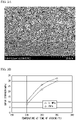
- Fig. 3A is a microscopic image of a cross section of a joined body obtained by joining by setting a pressure at 0.4 MPa and performing heat treatment at a temperature of 250°C in the atmosphere by the SEM.
- Fig. 3B is a graph showing the relationship between the shear strength of the joined body and the temperature and pressure at the time of sintering.
- Example 1 As a result, the joining material of Example 1 was applied in the atmosphere, and the silver-plated copper plate and the conductor could be joined. It was clear that, as the temperature at the time of sintering was high and as the pressure at the time of sintering was high, the shear strength increased.
- the conductor and the unplated copper plate were heat-treated to be joined in nitrogen using the joining material of Example 14 at a pressure of 0.4 MPa or 1 MPa at temperatures of 250°C, 300°C, and 350°C to obtain a joined body.
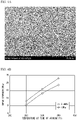
- Fig. 4A is SEM image data of a cross section of a joined body obtained by joining by setting a pressure at 0.4 MPa and performing heat treatment at a temperature of 300°C in nitrogen.
- Fig. 4B is a graph showing the relationship between the shear strength of the joined body and the temperature and pressure at the time of sintering.
- Example 14 As a result, the joining material of Example 14 was applied in nitrogen, and the unplated copper plate and the conductor could be directly joined. It was clear that, as the temperature at the time of sintering was high and as the pressure at the time of sintering was high, the shear strength increased.
- the present invention it is possible to provide a joining material used for producing a joined body having excellent joining strength compared with that of the related art, a method for producing the joining material, and a joined body using the joining material.
- the joining material of the present invention can be used at high temperatures (for example, 300°C or higher), which was difficult with the joining material of the related art, and is useful as a joining material for electronic components including power semiconductors using silicon carbide (SiC).
Landscapes
- Engineering & Computer Science (AREA)
- Mechanical Engineering (AREA)
- Manufacturing & Machinery (AREA)
- Chemical & Material Sciences (AREA)
- Materials Engineering (AREA)
- Composite Materials (AREA)
- Nanotechnology (AREA)
- Dispersion Chemistry (AREA)
- Inorganic Chemistry (AREA)
- Metallurgy (AREA)
- Organic Chemistry (AREA)
- Powder Metallurgy (AREA)
- Laminated Bodies (AREA)
- Ceramic Products (AREA)
Abstract
Description
- The present invention relates to a joining material, a method for producing a joining material, and a joined body. Priority is claimed on
Japanese Patent Application No. 2019-188913, filed October 15, 2019 - A power semiconductor using silicon carbide (SiC) is smaller in size than a semiconductor using silicon of the related art, has a feature of reducing energy loss, and can operate even at a high temperature of 300°C or higher.
- In a case of operating a SiC power semiconductor at a high temperature, solder of the related art having a heat-resistant temperature of approximately 150°C in an operating environment is not suitable as a joining material. As an alternative joining material, a paste (metal fine particle paste) in which metal fine particles are dispersed in a solvent and which is excellent in heat resistance and electrical conductivity is being studied.
- However, in a case where a substrate and a chip are joined at a high temperature using the metal fine particle paste, there is a problem in that the solvent volatilizes at the time of joining and large pores (voids) are generated at a joined portion, or a position of the chip is shifted in the obtained joined body.
- On the other hand, in order to suppress the formation of large pores in the joined portion, a method for producing a joining material by molding silver particles while pressurizing and joining base materials by using this joining material is known (see Patent Document 1).
- [Patent Document 1]
Japanese Patent No. 4876979 - However, in a case where a substrate and a chip are joined at a high temperature using the joining material described in
Patent Document 1, there is a problem in that the joining strength of the obtained joined body is not sufficient. - Therefore, an object of the present invention is to provide a joining material capable of producing a joined body having excellent joining strength compared with that of the related art, a method for producing the joining material, and a joined body using the joining material.
- In order to solve the aforementioned problems, the present invention has adopted the following configuration.
- That is, according to a first aspect of the present invention, a joining material is provided containing a sintered body formed by sintering silver powder, in which a porosity of the sintered body is 8% to 30%, and a surface roughness Ra of a joining surface is 500 nm or more and 3.3 µm or less.
- According to a second aspect of the present invention, a method for producing a joining material is provided, the method including a step of heating a coating film formed by using a dispersion liquid of a solvent and silver powder to obtain a sintered body, in which a content of the solvent in the dispersion liquid is 5% by mass or more and 25% by mass or less.
- According to a third aspect of the present invention, a method for producing a joining material is provided, the method including a step of heating a coating film formed by using a dispersion liquid of a solvent and silver powder to obtain a sintered body, in which the silver powder contains a first silver particle group and a second silver particle group having different average particle diameters, an average particle diameter of the first silver particle group is 50 nm or more and less than 1000 nm, and an average particle diameter of the second silver particle group is 1 µm or more and less than 20 µm.
- In the method for producing a joining material according to the third aspect, it is preferable that the silver powder further contain a third silver particle group having an average particle diameter of 20 µm or more and less than 60 µm.
- In the method for producing a joining material according to the second or third aspect, it is preferable that, in the step of obtaining the sintered body, the coating film be heated while applying a pressure of 5 MPa or less to the coating film.
- It is preferable that the method for producing a joining material according to the second or third aspect further include a step of polishing a surface of the sintered body, or a step of performing plating with one or more selected from the group consisting of silver, copper, tin, gold, and nickel on the surface of the sintered body.
- According to a fourth aspect of the present invention, a joined body is provided including a conductor and a substrate that are joined by the joining material according to the first aspect.
- According to the present invention, it is possible to provide a joining material capable of producing a joined body having excellent joining strength compared with that of the related art, a method for producing the joining material, and a joined body using the joining material.
-
-
Fig. 1 is a cross-sectional view showing an embodiment of a joined body according to the present invention. -
Fig. 2A is a microscopic image of a cross section of a joining material obtained by a scanning electron microscope. -
Fig. 2B is a microscopic image of a cross section of a joining material obtained by a scanning electron microscope. -
Fig. 2C is a microscopic image of a cross section of a joining material obtained by a scanning electron microscope. -
Fig. 2D is a microscopic image of a cross section of a joining material obtained by a scanning electron microscope. -
Fig. 2E is a microscopic image of a cross section of a joining material obtained by a scanning electron microscope. -
Fig. 3A is a microscopic image of a vicinity of a joined portion between a joining material according to the present invention and a silver-plated copper plate. -
Fig. 3B is a graph showing a relationship between a shear strength of the joined body according to the present invention and a temperature and a pressure at the time of sintering. -
Fig. 4A is a microscopic image of a vicinity of a joined portion between the joining material according to the present invention and an unplated copper plate. -
Fig. 4B is a graph showing the relationship between the shear strength of the joined body according to the present invention and the temperature and pressure at the time of sintering. -
Fig. 1 is a cross-sectional view showing an embodiment of a joined body according to the present invention. - A joined
body 10 shown inFig. 1 is a laminate in which aconductor 12 and asubstrate 14 are joined by a joiningmaterial 13. - The joined
body 10 of the present embodiment is characterized by the joiningmaterial 13, and various well-known joined bodies can be suitably applied to other configurations. - The joining material of the present embodiment contains a sintered body formed by sintering silver powder, a porosity of the sintered body is 8% to 30%, and a surface roughness Ra of a joining surface is 500 nm or more and 3.3 µm or less.
- In the present specification, the joining material contains a material for joining two objects, and typically contains a material for joining a conductor and a substrate by being interposed therebetween.
- The porosity of the sintered body contained in the joining material of the present embodiment is 8% to 30%, preferably 8% to 20%, and more preferably 9% to 15%.
- When the porosity of the sintered body is within the range described above, for example, it can be said that a joining strength between the conductor and the substrate (shear strength of the joined body) is excellent.
- Here, the shear strength means a strength measured by a method based on JIS Z 3198-7:2003. A specific measurement method will be described later in the examples.
- In the present specification, the porosity of the sintered body is measured as follows.
- First, the sintered body is immersed in water to measure a volume of the sintered body, and a mass of the sintered body is measured. In addition, the volume in a case where the sintered body does not have pores corresponding to the mass thereof is calculated based on a theoretical density. The porosity of the sintered body is calculated from the measured volume and the theoretical volume in a case where there are no pores.
- As a method for controlling the porosity of the sintered body contained in the joining material of the present embodiment within the range described above, for example, a method for suitably selecting the kind or the particle diameter of silver powder, a method for suitably setting a pressure condition at the time of sintering, a method for adjusting the amount of a solvent of a dispersion liquid in a case of producing the joining material by using the dispersion liquid of the silver powder, and the like are exemplary examples.
- The joining material of the present embodiment may contain a substance other than the sintered body formed from the silver powder, as long as the shear strength of the joined body is sufficient.
- A shape of the joining material of the present embodiment is not particularly limited, and a flat plate shape such as a disk, a rectangular plate, and the like; a rod shape such as a cylindrical shape, a columnar shape, a polygonal cylindrical shape, a polygonal columnar shape, and the like, and a spherical shape are exemplary examples.
- In addition, the joining material of the present embodiment may have a thick portion having a thickness of 1 mm or less, in order to facilitate joining.
- A size of the joining material is not particularly limited, and may be suitably adjusted according to specifications of the substrate and the conductor. In a case where the shape of the joining material is a disk shape, a diameter of the disk is preferably 0.5 to 50 mm and more preferably 2 to 30 mm. In a case where the shape of the joining material is a rectangular plate shape, a length of a long side is preferably 0.5 to 50 mm and more preferably 2 to 30 mm.
- A surface roughness Ra of the joining surface in the joining material of the present embodiment is 500 nm or more, preferably 800 nm or more, more preferably 1.06 µm or more, and even more preferably 1.4 µm or more.
- In addition, the surface roughness Ra of the joining surface in the joining material of the present embodiment is 3.3 µm or less, preferably 3.1 µm or less, more preferably 2.9 µm or less, and even more preferably 2.8 µm or less.
- An upper limit value and a lower limit value of the surface roughness Ra of the joining surface in the joining material of the present embodiment may be arbitrarily combined.
- The combination of the upper limit value and the lower limit value of the surface roughness Ra is 500 nm or more and 3.3 µm or less, preferably 800 nm or more and 3.3 µm or less, more preferably 1.06 µm or more and 3.3 µm or less, and even more preferably 1.4 µm or more and 2.8 µm or less.
- As will be described later in the examples, in a case where the surface roughness Ra of the joining surface is within the range described above, the shear strength of the joined body can be excellent.
- In the joining material of the present embodiment, the numerical ranges of the porosity of the sintered body and the surface roughness Ra of the joining surface defined above may be arbitrarily combined.
- The combination of the porosity of the sintered body and the surface roughness Ra of the joining surface is a porosity of 8% to 30% and a surface roughness Ra of 500 nm or more and 3.3 µm or less, preferably a porosity of 8% to 30% and a surface roughness Ra of 1.06 µm or more and 3.3 µm or less, more preferably a porosity of 8% to 27% and a surface roughness Ra of 1.06 µm or more and 2.8 µm or less, and even more preferably a porosity of 8% to 27%, and a surface roughness Ra of 1.4 µm or more and 2.8 µm or less.
- The surface roughness of the joining surface of the joining material can be measured as follows. The surface roughness is measured for five arbitrary points of the surface of the joining material by using an ultra-depth color 3D shape-measuring microscope (KEYENCE, VK-9510), and an average value is calculated.
- The method for controlling the surface roughness Ra of the joining surface of the joining material within the range described above is not particularly limited, and a method for polishing the surface of the sintered body, a method for plating the surface of the sintered body, and the like are exemplary examples. The kind of plating is not particularly limited, and plating with one kind of metal selected from the group consisting of silver, copper, tin, gold, and nickel, or with an alloy consisting of two or more thereof is exemplary. For the plating, overlapping plating of two or more layers having different compositions may be used.
- In the joining material of the present embodiment, in a case where the surface of the sintered body is polished, the surface roughness Ra of the joining surface of the joining material is 500 nm or more, preferably 1.06 µm or more, more preferably 1.5 µm or more, and even more preferably 1.7 µm or more.
- In the joining material of the present embodiment, in a case where the surface of the sintered body is polished, the surface roughness Ra of the joining surface of the joining material is 3.3 µm or less, preferably 3.1 µm or less, more preferably 2.9 µm or less, and even more preferably 2.8 µm or less.
- The upper limit value and the lower limit value of the surface roughness Ra of the joining surface in the joining material may be arbitrarily combined.
- In the joining material of the present embodiment, in a case where the surface of the sintered body is polished, the combination of the upper limit value and the lower limit value of the surface roughness Ra of the joining surface of the joining material is 500 nm or more and 3.3 µm or less, preferably 1.06 µm or more and 3.3 µm or less, more preferably 1.5 µm or more and 2.9 µm or less, and even more preferably 1.7 µm or more and 2.8 µm or less.
- In the joining material of the present embodiment, in a case where the surface of the sintered body is polished, the numerical ranges of the porosity of the sintered body and the surface roughness Ra of the joining surface defined above may be arbitrarily combined.
- In the joining material of the present embodiment, in a case where the surface of the sintered body is polished, the combination of the porosity of the sintered body and the surface roughness Ra of the joining surface is a porosity of 8% to 30% and a surface roughness Ra of 500 nm or more and 3.3 µm or less, preferably a porosity of 8% to 30% and a surface roughness Ra of 1.06 µm or more and 3.3 µm or less, more preferably a porosity of 8% to 27% and a surface roughness Ra of 1.5 µm or more and 3.1 µm or less, and even more preferably a porosity of 8% to 27%, and a surface roughness Ra of 1.7 µm or more and 2.8 µm or less.
- In the joining material of the present embodiment, in a case where the surface of the sintered body is plated, the surface roughness Ra of the joining surface of the joining material is 500 nm or more, preferably 800 nm or more, more preferably 1.06 µm or more, and even more preferably 1.4 µm or more.
- In the joining material of the present embodiment, in a case where the surface of the sintered body is plated, the surface roughness Ra of the joining surface of the joining material is 3.3 µm or less, preferably 2.5 µm or less, more preferably 2.0 µm or less, and even more preferably 1.8 µm or less.
- The upper limit value and the lower limit value of the surface roughness Ra of the joining surface in the joining material may be arbitrarily combined.
- In the joining material of the present embodiment, in a case where the surface of the sintered body is plated, the combination of the upper limit value and the lower limit value of the surface roughness Ra of the joining surface of the joining material is 500 nm or more and 3.3 µm or less, preferably 1.06 µm or more and 3.3 µm or less, more preferably 1.06 µm or more and 2.0 µm or less, and even more preferably 1.4 µm or more and 1.8 µm or less.
- In the joining material of the present embodiment, in a case where the surface of the sintered body is plated, the numerical ranges of the porosity of the sintered body and the surface roughness Ra of the joining surface defined above may be arbitrarily combined.
- In the joining material of the present embodiment, in a case where the surface of the sintered body is plated, the combination of the porosity of the sintered body and the surface roughness Ra of the joining surface is a porosity of 8% to 30% and a surface roughness Ra of 500 nm or more and 3.3 µm or less, preferably a porosity of 8% to 27% and a surface roughness Ra of 1.06 µm or more and 3.3 µm or less, more preferably a porosity of 9% to 15% and a surface roughness Ra of 1.06 µm or more and 2.0 µm or less, and even more preferably a porosity of 9% to 13%, and a surface roughness Ra of 1.4 µm or more and 1.8 µm or less.
- The joining material of the present embodiment described above contains a sintered body of silver powder having a porosity of the sintered body of 8% to 30%, and a surface roughness Ra of the joining surface of 500 nm or more and 3.3 µm or less. As described above, since the sintered body of silver powder having the surface roughness Ra of the joining surface in the specific range and the specific porosity is adopted, according to the joining material of the present embodiment, a joined body having excellent joining strength compared with that of the related art can be produced.
- In addition, the sintered body does not melt even at a temperature higher than a melting point of the silver powder. Further, by using the joining material containing this sintered body, it is possible to perform joining at a temperature lower than the melting point of the bulk.
- The method for producing the joining material of the present embodiment includes a step of heating a coating film formed by using a dispersion liquid of a solvent and silver powder to obtain a sintered body.
- The dispersion liquid of the present embodiment is obtained by dispersing the silver powder in a solvent.
- As the solvent used herein, water, an alcohol-based solvent, a glycol ether-based solvent, terpineols, and the like are exemplary examples.
- As alcohol-based solvents, isopropyl alcohol, 1,2-butanediol, isobornyl cyclohexanol, 2,4-diethyl-1,5-pentanediol, 2,2-dimethyl-1,3-propanediol, 2,5-dimethyl-2,5-hexanediol, 2,5-dimethyl-3-hexyne-2,5-diol, 2,3-dimethyl-2,3-butanediol, 1,1,1-tris (hydroxymethyl) ethane, 2-ethyl-2-hydroxymethyl-1,3-propanediol, 2,2'-oxybis (methylene) bis (2-ethyl-1,3-propanediol), 2,2-bis (hydroxymethyl)-1,3-propanediol, 1,2,6-trihydroxyhexane, bis [2,2,2-tris (hydroxymethyl) ethyl] ether, 1-ethynyl-1-cyclohexanol, 1,4-cyclohexanediol, 1,4-cyclohexanedimethanol, erythritol, threitol, guaiacol glycerol ether, 3,6-dimethyl-4-octyne-3,6-diol, 2,4,7,9-tetramethyl-5-decyne-4,7-diol, and the like are exemplary examples.
- As the glycol ether-based solvent, diethylene glycol mono-2-ethylhexyl ether, ethylene glycol monophenyl ether, 2-methylpentane-2,4-diol, diethylene glycol monohexyl ether, diethylene glycol dibutyl ether, and triethylene glycol monobutyl ether, and the like are exemplary examples.
- As the silver powder used herein, it is preferable to use a combination of silver particle groups having different average particle diameters. By using silver particle groups having different average particle diameters in combination, a joining material having a specific porosity (8% to 30%) can be easily produced.
- For the average particle diameter of the silver particle group, a value of a median diameter D50 is adopted. In the present invention, the median diameter D50 of each silver powder means a diameter measured by a laser diffraction method (volume-average particle diameter) using SALD-2300 (manufactured by Shimadzu Corporation).
- As a preferable combination of silver particle groups having different average particle diameters, a combination of a nano-order silver particle group and a micro-order silver particle group is used.
- For example, it is preferable that the first silver particle group and the second silver particle group having different average particle diameters be included, the average particle diameter of the first silver particle group be 50 nm or more and less than 1000 nm, and the average particle diameter of the second silver particle group be 1 µm or more and less than 20 µm.
- The average particle diameter of the first silver particle group is 50 nm or more and less than 1000 nm, preferably 100 nm or more and 800 nm or less, and more preferably 200 nm or more and 500 nm or less.
- The average particle diameter of the second silver particle group is 1 µm or more and less than 20 µm, preferably 3 µm or more and 15 µm or less, and more preferably 3 µm or more and 10 µm or less.
- By using the first silver particle group and the second silver particle group in combination, a joining material having a specific porosity (8% to 30%) can be easily produced, and a joined body having an increased joining strength can be easily obtained.
- A shape of the silver particle of the first silver particle group is not particularly limited, and may be any of a spherical or non-spherical shape. As the non-spherical shape, a flake shape, a needle shape, a horn shape, a branch shape, a granular shape, an irregular shape, a teardrop shape, a plate shape, an ultrathin plate shape, a hexagonal plate shape, a columnar shape, a rod shape, a porous shape, a fibrous shape, a lump shape, a sponge shape, an inclined shape, a round shape, and the like are exemplary examples. Among such shapes, the spherical and columnar shapes are preferable.
- The second silver particle group preferably contains flake-shaped silver particles. In this case, the second silver particle group may be such that the majority of the silver particles are recognized as the flake shape (shape of thin pieces or chips) under a microscope. Typically, it means that 51% by mass or more of the particles (primary particles) constituting the second silver particle group have a flake (thin pieces or chips) shape. Here, particles having the flake shape (shape of thin pieces or chips) mean particles having an aspect ratio (ratio of longest major axis/shortest minor axis) of 5 to 300.
- The silver powder of the present embodiment may further contain a third silver particle group having an average particle diameter of 20 µm or more and less than 60 µm.
- The average particle diameter of the third silver particle group is 20 µm or more and less than 60 µm, preferably 30 µm or more and 50 µm or less, and more preferably 35 µm or more and 45 µm or less.
- By further using the third silver particle group in addition to the first silver particle group and the second silver particle group in combination, a joining material having a specific porosity (8% to 30%) can be produced more stably.
- A shape of the silver particle of the third silver particle group is not particularly limited, and may be any of a spherical or non-spherical shape. As the non-spherical shape, a flake shape, a needle shape, a horn shape, a branch shape, a granular shape, an irregular shape, a teardrop shape, a plate shape, an ultrathin plate shape, a hexagonal plate shape, a columnar shape, a rod shape, a porous shape, a fibrous shape, a lump shape, a sponge shape, an inclined shape, a round shape, and the like are exemplary examples. Among such shapes, the spherical and columnar shapes are preferable.
- In addition, as the first silver particle group, the second silver particle group, and the third silver particle group, two or more kinds having different average particle diameters may be used as each silver particle group.
- In the silver powder of the present embodiment, it is preferable to use two or more kinds having different average particle diameters as the second silver particle group. For example, as the second silver particle group, it is preferable to use the silver particle group having an average particle diameter of 1 µm or more and less than 10 µm and the silver particle group having an average particle diameter of 10 µm or more and less than 20 µm in combination.
- In a case where the silver particle groups having different average particle diameters are used in combination as the silver powder of the present embodiment, a percentage of the first silver particle group is preferably 1 to 50% by mass, more preferably 1 to 30% by mass, and even more preferably 3 to 10% by mass with respect to a total mass (100% by mass) of the silver powder.
- A percentage of the second silver particle group is preferably 30 to 99% by mass, more preferably 45 to 90% by mass, and even more preferably 50 to 90% by mass with respect to the total mass (100% by mass) of the silver powder.
- In a case of further using the third silver particle group in combination, a percentage of the third silver particle group is preferably 1 to 70% by mass, more preferably 1 to 50% by mass, and even more preferably 1 to 45% by mass with respect to a total mass (100% by mass) of the silver powder. However, a sum of the percentages of the first silver particle group, the second silver particle group, and the third silver particle group does not exceed 100% by mass.
- In the dispersion liquid of the solvent and the silver powder in the present embodiment, a content of the solvent in the dispersion liquid is preferably 5% by mass or more and 25% by mass or less, more preferably 5% by mass or more and 20% by mass or less, even more preferably 5% by mass or more and 15% by mass or less, and particularly preferably 6% by mass or more and 10% by mass or less.
- By setting the content of the solvent in the dispersion liquid to 5% by mass or more and 25% by mass or less, a sintered body having a porosity of 8% to 30% can be easily obtained.
- When the dispersion liquid is sintered, the solvent in the dispersion liquid is volatilized and the pores are formed in the sintered body. By setting the content of the solvent in the dispersion liquid within the range described above, the porosity of the sintered body can be set to 8% to 30%.
- Next, the method for producing the joining material of the present embodiment will be described in detail.
- In the step of obtaining the sintered body of the present embodiment, a coating film formed by using a dispersion liquid of a solvent and silver powder is heated to obtain a sintered body.
- First, the dispersion liquid described above is applied onto a base to form a coating film. The method for coating is not particularly limited, and dispensing coating, print coating, spray coating, brush coating, injection, and the like are exemplary examples.
- As a material of the base, glass, quartz, silicon, metal, and the like are exemplary examples, but there is no limitation thereto. As will be described later in the examples, for example, brass can be used as the metal, but the metal is not limited thereto.
- When using a metal base, if a lubricating mold release agent is applied to the base in advance, the sintered body can be easily peeled off from the base.
- Next, the coating film is heated to obtain the sintered body. A heating temperature can be suitably set, as long as it is a temperature at which the sintered body can be obtained, and is, for example, preferably 150°C or higher and 300°C or lower and more preferably 200°C or higher and 250°C or lower.
- The time for heating the coating film can be suitably set, as long as it is the time during which the sintered body can be obtained, and is, for example, preferably 15 minutes or longer and 180 minutes or shorter and more preferably 30 minutes or longer and 90 minutes or shorter.
- In the step of obtaining the sintered body in the present embodiment, a pressure applied to the coating film can be preferably suppressed to 5 MPa or less, can be suppressed to 1 MPa or less, and particularly can also be no pressurization.
- Next, the obtained sintered body may be cut according to the specifications of the substrate and the conductor. A tool used for cutting the sintered body is not particularly limited, and scissors, a diamond knife, a paper cutter, and the like are exemplary examples. In the present specification, the cut sintered body described above may be simply referred to as the sintered body.
- More specifically, the following embodiments are preferably used as the method for producing the joining material described above.
- Embodiment (i): A method for producing a joining material, the method including a step of heating a coating film formed by using a dispersion liquid of a solvent and silver powder to obtain a sintered body, in which a content of the solvent in the dispersion liquid is 5% by mass or more and 25% by mass or less.
- According to the embodiment (i), by setting the content of the solvent in the dispersion liquid to a specific ratio, a joining material containing a sintered body having a porosity of 8% to 30% can be easily produced.
- Embodiment (ii): A method for producing a joining material, the method including a step of heating a coating film formed by using a dispersion liquid of a solvent and silver powder to obtain a sintered body, in which a content of the solvent in the dispersion liquid is 5% by mass or more and 25% by mass or less, the silver powder consists of a first silver particle group and a second silver particle group having different average particle diameters, an average particle diameter of the first silver particle group is 50 nm or more and less than 1000 nm, and an average particle diameter of the second silver particle group is 1 µm or more and less than 20 µm.
- In the silver powder, for example, a percentage of the first silver particle group may be 1 to 50% by mass, and a percentage of the second silver particle group may be 50 to 99% by mass.
- In the silver powder, for example, the percentage of the first silver particle group may be 5 to 30% by mass, and the percentage of the second silver particle group may be 70 to 95% by mass.
- In the silver powder, for example, the percentage of the first silver particle group may be 5 to 15% by mass, and the percentage of the second silver particle group may be 85 to 95% by mass.
- The percentage of the first silver particle group and the second silver particle group is the percentage with respect to the total mass (100% by mass) of the silver powder. In addition, a sum of the percentages of the first silver particle group and the second silver particle group does not exceed 100% by mass.
- According to the embodiment (ii), by using the silver particle groups having specific average particle diameters in combination, a joining material containing a sintered body having a porosity of 8% to 30% can be easily produced.
- Embodiment (iii): A method for producing a joining material, the method including a step of heating a coating film formed by using a dispersion liquid of a solvent and silver powder to obtain a sintered body, in which a content of the solvent in the dispersion liquid is 5% by mass or more and 25% by mass or less, the silver powder consists of a first silver particle group, a second silver particle group, a third silver particle group having different average particle diameters, an average particle diameter of the first silver particle group is 50 nm or more and less than 1000 nm, an average particle diameter of the second silver particle group is 1 µm or more and less than 20 µm, and an average particle diameter of the third silver particle group is 20 µm or more and less than 60 µm.
- In the silver powder, for example, a percentage of the first silver particle group may be 1 to 50% by mass, a percentage of the second silver particle group may be 30 to 98% by mass, and a percentage of the third silver particle group may be 1 to 69% by mass.
- In the silver powder, for example, the percentage of the first silver particle group may be 1 to 30% by mass, the percentage of the second silver particle group may be 30 to 90% by mass, and the percentage of the third silver particle group may be 5 to 60% by mass.
- In the silver powder, for example, the percentage of the first silver particle group may be 3 to 8% by mass, the percentage of the second silver particle group may be 45 to 72% by mass, and the percentage of the third silver particle group may be 20 to 50% by mass.
- The percentage of the first silver particle group, the second silver particle group, and the third silver particle group is the percentage with respect to the total mass (100% by mass) of the silver powder. However, a sum of the percentages of the first silver particle group, the second silver particle group, and the third silver particle group does not exceed 100% by mass.
- According to the embodiment (iii), by using the silver particle groups having specific average particle diameters in combination, a joining material containing a sintered body having a porosity of 8% to 30% can be easily produced.
- The method for producing a joining material of the present embodiment may include other steps in addition to the step of obtaining a sintered body.
- For example, in order to control the roughness of the surface of the obtained sintered body, the method may further include a step of polishing a surface of the sintered body, or a step of performing plating with one or more selected from the group consisting of silver, copper, tin, gold, and nickel on the surface of the sintered body, on the subsequent stage side of the step of obtaining the sintered body.
- In a case where the method for producing the joining material of the present embodiment includes the step of polishing the surface of the sintered body or the step of performing the plating, the surface roughness Ra of the joining surface in the joining material obtained by the step of polishing or the step of performing the plating is 500 nm or more, preferably 800 nm or more, more preferably 1.06 µm or more, and even more preferably 1.4 µm or more.
- On the other hand, the upper limit of the surface roughness Ra of the joining surface of the joining material obtained by the step of polishing or the step of performing the plating is 3.3 µm or less, preferably 3.1 µm or less, more preferably 2.9 µm or less, and even more preferably 2.8 µm or less.
- The upper limit value and the lower limit value of the surface roughness Ra of the joining surface in the joining material obtained by the step of polishing or the step of performing the plating may be arbitrarily combined.
- The combination of the upper limit value and the lower limit value of the surface roughness Ra of the joining surface of the joining material obtained by the step of polishing or the step of performing the plating is 500 nm or more and 3.3 µm or less, preferably 800 nm or more and 3.3 µm or less, more preferably 1.06 µm or more and 3.3 µm or less, and even more preferably 1.4 µm or more and 2.8 µm or less.
- The method for polishing the surface of the sintered body is not particularly limited, and chemical polishing, electrolytic polishing, mechanical polishing, and the like are exemplary examples. As will be described later in the examples, by polishing the surface of the sintered body with abrasive paper No. 2000, a joining material capable of producing a joined body having sufficient joining strength can be obtained.
- In a case where the method for producing the joining material of the present embodiment includes the step of polishing the surface of the sintered body, the surface roughness Ra of the joining surface in the joining material obtained by the step of polishing is 500 nm or more, preferably 1.06 µm or more, more preferably 1.5 µm or more, and even more preferably 1.7 µm or more.
- On the other hand, the surface roughness Ra of the joining surface of the joining material obtained by the step of polishing is 3.3 µm or less, preferably 3.1 µm or less, more preferably 2.9 µm or less, and even more preferably 2.8 µm or less.
- The upper limit value and the lower limit value of the surface roughness Ra of the joining surface in the joining material obtained by the step of polishing may be arbitrarily combined.
- The combination of the upper limit value and the lower limit value of the surface roughness Ra of the joining surface of the joining material obtained by the step of polishing is 500 nm or more and 3.3 µm or less, preferably 1.06 µm or more and 3.3 µm or less, more preferably 1.5 µm or more and 2.9 µm or less, and even more preferably 1.7 µm or more and 2.8 µm or less.
- The method for plating the surface of the sintered body is not particularly limited, and electroplating, electroless plating, vacuum plating, and the like are exemplary examples. The kind of plating is not particularly limited, and plating with one kind of metal selected from the group consisting of silver, copper, tin, gold, and nickel, or with an alloy consisting of two or more thereof is exemplary. The step of performing the plating may be plating by overlapping two or more layers of plating having different compositions.
- For example, in a case where one of the objects to be joined is a copper substrate, the surface of the sintered body may be copper-plated. Accordingly, the affinity between the joining material and the copper substrate is strengthened, and the joining strength is likely to be increased.
- In a case where the method for producing the joining material of the present embodiment includes the step of performing the plating of the surface of the sintered body, the surface roughness Ra of the joining surface in the joining material obtained by the step of performing the plating is 500 nm or more, preferably 800 nm or more, more preferably 1.06 µm or more, and even more preferably 1.4 µm or more.
- On the other hand, the surface roughness Ra of the joining surface of the joining material obtained by the step of performing the plating is 3.3 µm or less, preferably 2.5 µm or less, more preferably 2.0 µm or less, and even more preferably 1.8 µm or less.
- The upper limit value and the lower limit value of the surface roughness Ra of the joining surface in the joining material obtained by the step of performing the plating may be arbitrarily combined.
- The surface roughness of the joining surface of the joining material obtained by the step of performing the plating is 500 nm or more and 3.3 µm or less, preferably 1.06 µm or more and 3.3 µm or less, more preferably 1.06 µm or more and 2.0 µm or less, and even more preferably 1.4 µm or more and 1.8 µm or less.
- In a case where the method for producing the joining material includes the step of polishing the surface of the sintered body or the step of performing the plating at the subsequent stage side of the embodiment (i) of the step of obtaining the sintered body, in the joining material to be obtained, the surface roughness Ra of the joining surface is in the specific range and the sintered body has the specific porosity.
- In a case where the method for producing the joining material includes the step of polishing the surface of the sintered body or the step of performing the plating at the subsequent stage side of the embodiment (ii) of the step of obtaining the sintered body, in the joining material to be obtained, the surface roughness Ra of the joining surface is in the specific range, and for the sintered body, the sintered body of the silver powder having the specific porosity is obtained.
- In a case where the method for producing the joining material includes the step of polishing the surface of the sintered body or the step of performing the plating at the subsequent stage side of the embodiment (iii) of the step of obtaining the sintered body, in the joining material to be obtained, the surface roughness Ra of the joining surface is in the specific range, and for the sintered body, the sintered body of the silver powder having the specific porosity is obtained.
- In the joined body of the present embodiment, as shown in
Fig. 1 , the conductor and the substrate are joined by the joining material described above. - As the conductor, a chip part such as a condenser and a resistor, or a Si chip, a SiC chip, GaN, and the like obtained by forming a semiconductor element such as a resistor, a transistor, a condenser, and an integrated circuit on a wafer and cutting out a section of each semiconductor element from the wafer, and the like are exemplary examples.
- As the substrate, a circuit board, a glass fiber-reinforced epoxy-based printed circuit board, a polyimide-based substrate, a ceramics substrate, a metal substrate, a Cu lead frame, and the like are exemplary examples.
- A temperature at the time of joining is, for example, preferably 150°C or higher and 400°C or lower and more preferably 200°C or higher and 300°C or lower.
- As the method for joining the conductor and the substrate by using the joining material described above, a well-known method can be adopted.
- A pressure at the time of joining is not particularly limited, and may be, for example, 0.1 MPa or more and 3 MPa or less.
- The atmosphere at the time of joining may be the atmosphere or nitrogen.
- In the joined body of the present embodiment described above, the joining material containing the sintered body of the silver powder having a porosity of 8% to 30% and having the surface roughness Ra of the joining surface of 500 nm or more and 3.3 µm or less is applied. Therefore, such a joined body has excellent joining strength compared with that of the related art.
- Hereinafter, the present invention will be described with reference to Examples, but the present invention is not limited to the following Examples.
- Silver particle groups shown below were used as the silver powder.
- Silver particle group 1A: Average particle diameter of 300 nm
- Silver particle group 2A: Average particle diameter of 4 µm
- Silver particle group 2B: Average particle diameter of 10 µm
- Silver particle group 3: Average particle diameter of 42 µm
- Silver particle group 1B: Average particle diameter of 50 nm
- The shape of the silver particles of the silver particle groups 1A, 1B, 2A, and 3 was a spherical shape, and the shape of the silver particles of the silver particle group 2B was a flake shape.
- Ethylene glycol was used as the solvent.
- For the average particle diameter described above, the value of the median diameter D50 was adopted. In the present invention, the median diameter D50 of each silver powder means a diameter measured by a laser diffraction method (volume-average diameter) using SALD-2300 (manufactured by Shimadzu Corporation).
- The silver particle group and the solvent described above were mixed in the composition shown in Table 1 to prepare
dispersion liquids 1 to 9. In Table 1, each value of the silver particle groups indicates the percentage (mass%) of the mass of each silver particle group with respect to the total mass of the silver powder. In addition, the percentage of the solvent indicates the percentage (mass%) of the mass of the solvent with respect to the total mass of the silver powder and the solvent.[Table 1] Composition of dispersion liquid Composition of silver powder Solvent Silver powder Silver particle group 1A Silver particle group 1B Silver particle group 2A Silver particle group 2B Silver particle group 3 Dispersion liquid 16 94 10 0 40 50 0 Dispersion liquid 2 6 94 5 0 20 25 50 Dispersion liquid 3 6 94 8 0 32 40 20 Dispersion liquid 4 6 94 3 0 12 40 45 Dispersion liquid 513.1 86.9 5 0 20 25 50 Dispersion liquid 6 17.9 82.1 5 0 20 25 50 Dispersion liquid 7 6 94 0 100 0 0 0 Dispersion liquid 8 26 74 10 0 40 50 0 Dispersion liquid 9 26 74 5 0 20 25 50 - A coating film was produced on a brass base using the
dispersion liquid 1. - As the brass, brass consisting of 65% by mass of copper and 35% by mass of zinc was used.
- The produced coating film was heated at 200°C for 30 minutes without pressure to obtain a sintered body. The obtained sintered body was cut into small pieces (dimension of length × width: 3 mm × 3 mm) by using scissors.
- The surface of the sintered body of the obtained small piece was polished by using abrasive paper No. 2000 (water-resistant abrasive paper sheet manufactured by Sankyo Rikagaku Co., Ltd.) to obtain a joining material.
- A joining material was obtained in the same manner as in Example 1, except that the sintering conditions were changed to 250°C for 30 minutes.
- A coating film was produced on the brass base described above using the
dispersion liquid 1. - The produced coating film was heated at 200°C for 30 minutes without pressure to obtain a sintered body.
- The obtained sintered body was immersed in a solution obtained by dissolving silver acetoacetic acid in 2-ethylhexylamine and allowed to stand at 40°C for 10 minutes. Then, the sintered body was taken out from the mixed solution and dried.
- A joining material was obtained in the same manner as in Example 3, except that the sintering conditions were changed to 250°C for 30 minutes.
- A joining material was obtained in the same manner as in Example 1, except that the dispersion liquid used was changed to the dispersion liquid 2.
- A joining material was obtained in the same manner as in Example 5, except that the sintering conditions were changed to 250°C for 30 minutes.
- A joining material was obtained in the same manner as in Example 3, except that the dispersion liquid used was changed to the dispersion liquid 2.
- A joining material was obtained in the same manner as in Example 7, except that the sintering conditions were changed to 250°C for 30 minutes.
- A joining material was obtained in the same manner as in Example 2, except that the dispersion liquid used was changed to the dispersion liquid 3.
- A joining material was obtained in the same manner as in Example 2, except that the dispersion liquid used was changed to the dispersion liquid 4.
- A joining material was obtained in the same manner as in Example 5, except that the sintering conditions were changed to 250°C for 90 minutes.
- A joining material was obtained in the same manner as in Example 2, except that the dispersion liquid used was changed to the
dispersion liquid 5. - A joining material was obtained in the same manner as in Example 2, except that the dispersion liquid used was changed to the dispersion liquid 6.
- A coating film was produced on the brass base described above using the dispersion liquid 2.
- The produced coating film was heated at 250°C for 30 minutes without pressure to obtain a sintered body.
- The obtained sintered body was immersed in a solution obtained by dissolving copper (II) formate tetrahydrate (manufactured by Wako Pure Chemical Industries, Ltd., model number: LKJ3210, primary average particle diameter: 20 µm) in 2-ethylhexylamine in a nitrogen atmosphere, and allowed to stand at 140°C for 10 minutes. Then, the sintered body was taken out from the mixed solution and dried.
- A joining material was obtained in the same manner as in Example 1, except that the dispersion liquid used was changed to the dispersion liquid 7.
- A joining material was obtained in the same manner as in Comparative Example 1, except that the sintering conditions were changed to 250°C for 30 minutes and the sintering was performed while pressurizing at 0.4 MPa at the time of sintering.
- A joining material was obtained in the same manner as in Comparative Example 1, except that the sintering was performed while pressurizing at 0.4 MPa at the time of sintering.
- A joining material was obtained in the same manner as in Comparative Example 1, except that the sintering conditions were changed to 250°C for 30 minutes.
- A joining material was obtained in the same manner as in Example 1, except that the dispersion liquid used was changed to the dispersion liquid 7 and the surface of the sintered body was not polished.
- A joining material was obtained in the same manner as in Comparative Example 5, except that the sintering conditions were changed to 250°C for 30 minutes.
- A joining material was obtained in the same manner as in Example 2, except that the dispersion liquid used was changed to the dispersion liquid 8 and the surface of the sintered body was not polished.
- A joining material was obtained in the same manner as in Example 2, except that the dispersion liquid used was changed to the dispersion liquid 8.
- A joining material was obtained in the same manner as in Example 2, except that the dispersion liquid used was changed to the dispersion liquid 9 and the surface of the sintered body was not polished.
- A joining material was obtained in the same manner as in Example 2, except that the dispersion liquid used was changed to the dispersion liquid 9.
- For each of the joining materials obtained in Examples 1 to 14 and Comparative Examples 1 to 10, the porosity and the surface roughness were measured by the measurement method shown below.
- The volume of the joining material was measured by immersing the joining material in water, and the mass of the joining material was measured. In addition, the volume in a case where the joining material did not have pores corresponding to the mass thereof was calculated based on a theoretical density. The porosity was calculated from the measured volume and the theoretical volume in a case where there were no pores.
- The surface roughness was measured for five arbitrary points of the surface of the joining material by using an ultra-depth color 3D shape-measuring microscope (KEYENCE, VK-9510), and an average value was calculated. A size of the measurement point was 1400 µm × 1050 µm.
- Table 2 shows the sintering conditions, the porosity, and the surface roughness of each joining material obtained in Examples 1 to 14 and Comparative Examples 1 to 10.
[Table 2] Joining material Dispersion liquid Temperature and time at time of sintering Pressure at time of sintering Polishing, plating Porosity (%) Surface roughness (µm) Example 1 Dispersion liquid 1 200°C, for 30 minutes No pressure Polishing 10.9 2.64 Example 2 Dispersion liquid 1 250°C, for 30 minutes No pressure Polishing 10.6 2.79 Example 3 Dispersion liquid 1 200°C, for 30 minutes No pressure Silver plating 10.3 1.76 Example 4 Dispersion liquid 1 250°C, for 30 minutes No pressure Silver plating 9.7 1.62 Example 5 Dispersion liquid 2 200°C, for 30 minutes No pressure Polishing 13.9 2.45 Example 6 Dispersion liquid 2 250°C, for 30 minutes No pressure Polishing 13.1 2.36 Example 7 Dispersion liquid 2 200°C, for 30 minutes No pressure Silver plating 12.4 1.49 Example 8 Dispersion liquid 2 250°C, for 30 minutes No pressure Silver plating 11.3 1.53 Example 9 Dispersion liquid 3 250°C, for 30 minutes No pressure Polishing 10.1 1.78 Example 10 Dispersion liquid 4 250°C, for 30 minutes No pressure Polishing 10.8 2.12 Example 11 Dispersion liquid 2 250°C, for 90 minutes No pressure Polishing 8.6 2.49 Example 12 Dispersion liquid 5 250°C, for 30 minutes No pressure Polishing 17.2 2.76 Example 13 Dispersion liquid 6 250°C, for 30 minutes No pressure Polishing 26.3 2.61 Example 14 Dispersion liquid 2 250°C, for 30 minutes No pressure Copper plating 11.6 1.06 Comparative Example 1 Dispersion liquid 7 200°C, for 30 minutes No pressure Polishing 5.3 1.06 Comparative Example 2 Dispersion liquid 7 250°C, for 30 minutes Pressure Polishing 5.1 1.02 Comparative Example 3 Dispersion liquid 7 200°C, for 30 minutes Pressure Polishing 6.2 1.04 Comparative Example 4 Dispersion liquid 7 250°C, for 30 minutes No pressure Polishing 6.4 1.02 Comparative Example 5 Dispersion liquid 7 200°C, for 30 minutes No pressure None 6.3 3.54 Comparative Example 6 Dispersion liquid 7 250°C, for 30 minutes No pressure None 6.4 3.37 Comparative Example 7 Dispersion liquid 8 250°C, for 30 minutes No pressure None 36.3 5.76 Comparative Example 8 Dispersion liquid 8 250°C, for 30 minutes No pressure Polishing 36.3 2.75 Comparative Example 9 Dispersion liquid 9 250°C, for 30 minutes No pressure None 35.7 6.04 Comparative Example 10 Dispersion liquid 9 250°C, for 30 minutes No pressure Polishing 35.7 2.68 - In a case where the silver powder contains
silver particle group 1 and silver particle group 2 and the content of the solvent in the dispersion liquid is 5% by mass or more and 25% by mass or less, the porosity of the sintered body of the obtained joined body of Examples 1 to 14 was 8% to 30%. - After embedding the obtained sintered body with a resin, a sintered body embedded with the resin was cut using an ion milling device IM4000PLUS (manufactured by Hitachi High-Technologies Corporation) to obtain a smoothed section. The obtained section was observed using a scanning electron microscope (SEM). A microscopic image of a cross section of the joining material obtained by an SEM is shown in
Fig. 2 . -
Fig. 2A is a microscopic image of a cross section of the joining material of Example 2 obtained by the SEM.Fig. 2B is a microscopic image of a cross section of the joining material of Example 6 obtained by the SEM.Fig. 2C is a microscopic image of a cross section of the joining material of Comparative Example 4 obtained by the SEM.Fig. 2D is a microscopic image of a cross section of the joining material of Example 9 obtained by the SEM.Fig. 2E is a microscopic image of a cross section of the joining material of Example 10 obtained by the SEM. - As a result, on the cross sections of the joining materials of Examples 2, 6, 9, and 10, a larger number of pores were observed, compared to the cross section of the joining material of Comparative Example 4.
- As the conductor, a Si chip (dimensions of length × width: 3 mm × 3 mm) in which a Ti layer (thickness 40 nm) and an Ag layer (thickness 1000 nm) were laminated by sputtering was used in order from the Si chip side. As the joining material, each of the joining materials of Examples 1 to 14 and Comparative Examples 1 to 10 was used. The thickness of each joining material was 100 µm. A copper substrate was used as the substrate.
- After stacking the substrate, the joining material, and the conductor in this order so that the polished surface of the joining material is the joining surface, joining was performed by setting the pressure to 0.4 MPa in the atmosphere and performing heat treatment at a temperature of 250°C to obtain the joined body. Using the joining materials of Examples 1 to 14 and Comparative Examples 1 to 10, joined bodies of Examples 21 to 34 and Comparative Examples 11 to 20 were obtained.
- The shear strengths of the obtained joined bodies of Examples 21 to 34 and Comparative Examples 11 to 20 were measured by the following measurement method. The results are shown in Table 3.
- The shear strength of each of the joined bodies of Examples 21 to 34 and Comparative Examples 11 to 20 was measured as follows. The measurement results are shown in Table 3.
- For each of the obtained joined bodies, the shear strength (MPa) between the Si chip and the substrate was measured by the method based on JIS Z 3198-7:2003 under a condition of room temperature (25°C) by using a universal bond tester Nordson DAGE Series 4000 (manufactured by Nordson Corporation). Each sample was measured 5 times and an average value of shear strengths (MPa) was calculated.
[Table 3] Joined body Shear strength Example 21 21.2 Example 22 22.3 Example 23 21.6 Example 24 22.5 Example 25 22.0 Example 26 22.1 Example 27 23.1 Example 28 22.9 Example 29 24.3 Example 30 23.3 Example 31 25.8 Example 32 22.2 Example 33 21.7 Example 34 18.5 Comparative Example 11 12.5 Comparative Example 12 15.3 Comparative Example 13 13.2 Comparative Example 14 14.9 Comparative Example 15 0 Comparative Example 16 0 Comparative Example 17 0 Comparative Example 18 10.6 Comparative Example 19 0 Comparative Example 20 8.6 - In a case where the joining materials of Examples 1 to 14 having a porosity of 8% to 30% were used, the shear strengths of the joined bodies of Examples 21 to 34 were sufficient.
- In a case where the joining materials of Examples 1 to 14 having a surface roughness Ra of the joining surface of 500 nm or more and 3.3 µm or less were used, the shear strengths of the obtained joined bodies of Examples 21 to 34 were sufficient.
- In a case where the joining materials of Examples 1, 2, 5, 6, and 9 to 13 obtained by polishing the surface of the sintered body were used, the shear strengths of the obtained joined bodies of Examples 21, 22, 25, 26, and 29 to 33 were sufficient.
- In a case where the joining materials of Examples 3, 4, 7, 8, and 14 obtained by plating the surface of the sintered body were used, the shear strengths of the obtained joined bodies of Examples 23, 24, 27, 28, and 34 were sufficient.
- In a case where the content of the solvent in the dispersion liquid was increased within the range of 5% by mass or more and 25% by mass or less and the obtained joining materials of Examples 12 and 13 were used to obtain joined bodies, the shear strengths of the joined bodies of Examples 32 and 33 were sufficient.
- The joining materials of Comparative Examples 1 to 6 obtained by using the dispersion liquid containing only the silver particle group 1B had a porosity of the sintered body less than 8%, and shear strengths of the joined bodies of Comparative Examples 11 to 16 using these were not sufficient.
- The joining materials of Comparative Examples 7 to 10, in which the dispersion liquid having the content of the solvent of 26% was used, had a porosity of the sintered body greater than 30%, and shear strengths of the joined bodies of Comparative Examples 17 to 20 using these joining materials were not sufficient.
- In a case where the joining materials of Comparative Examples 5, 6, 7, and 9 in which the surface of the sintered body was not polished and not plated were used, the shear strengths of the obtained joined bodies of Comparative Examples 25, 26, 27, and 29 were not sufficient.
- In addition, as described below, by comparing the joining materials of the examples and the joining materials of the comparative examples under the condition (a) and the condition (b), the following shown below became clear.
-
- (1) Comparison between joining material of Example 2 and joining material of Comparative Example 8
- (2) Comparison between joining material of Example 6 and joining material of Comparative Example 10
- (3) Comparison between joining material of Example 12 and joining material of Comparative Example 10
- (4) Comparison between joining material of Example 13 and joining material of Comparative Example 10
- Comparison between joining material of Example 2 and joining material of Comparative Example 8:
- When producing the joining material, the
dispersion liquid 1 was used in Example 2 and the dispersion liquid 8 was used in Comparative Example 8, and the composition of the silver powder in the dispersion liquid was silver particle group 1A/silver particle group 2A/silver particle group 2B = 10/40/50 (% by mass) for both joining materials. - As for the sintering conditions, the temperature and time at the time of sintering were set to 250°C for 30 minutes, the pressure at the time of sintering was set to no pressure, and the surface of the sintered body was polished for both joining materials.
- The surface roughness (µm)/porosity (%)/shear strength (MPa) of the joined body in the joining material was as follows.
- In Example 2, 2.79 µm/10.6%/22.3 MPa (Example 22)
- In Comparative Example 8, 2.75 µm/36.3%/10.6 MPa (Comparative Example 18)
- Comparison between joining material of Example 6 and joining material of Comparative Example 10:
When producing the joining material, the dispersion liquid 2 was used in Example 6 and the dispersion liquid 9 was used in Comparative Example 10, and the composition of the silver powder in the dispersion liquid was silver particle group 1A/silver particle group 2A/silver particle group 2B/silver particle group 3 = 5/20/25/50 (% by mass) for both joining materials. - As for the sintering conditions, the temperature and time at the time of sintering were set to 250°C for 30 minutes, the pressure at the time of sintering was set to no pressure, and the surface of the sintered body was polished for both joining materials.
- The surface roughness (µm)/porosity (%)/shear strength (MPa) of the joined body in the joining material was as follows.
- In Example 6, 2.36 µm/13.1%/22.1 MPa (Example 26)
- In Comparative Example 10, 2.68 µm/35.7%/8.6 MPa (Comparative Example 20)
- Comparison between joining material of Example 12 and joining material of Comparative Example 10:
When producing the joining material, thedispersion liquid 5 was used in Example 12 and the dispersion liquid 9 was used in Comparative Example 10, and the composition of the silver powder in the dispersion liquid was silver particle group 1A/silver particle group 2A/silver particle group 2B/silver particle group 3 = 5/20/25/50 (% by mass) for both joining materials. - As for the sintering conditions, the temperature and time at the time of sintering were set to 250°C for 30 minutes, the pressure at the time of sintering was set to no pressure, and the surface of the sintered body was polished for both joining materials.
- The surface roughness (µm)/porosity (%)/shear strength (MPa) of the joined body in the joining material was as follows.
- In Example 12, 2.76 µm/17.2%/22.2 MPa (Example 32)
- In Comparative Example 10, 2.68 µm/35.7%/8.6 MPa (Comparative Example 20)
- Comparison between joining material of Example 13 and joining material of Comparative Example 10:
When producing the joining material, the dispersion liquid 6 was used in Example 13 and the dispersion liquid 9 was used in Comparative Example 10, and the composition of the silver powder in the dispersion liquid was silver particle group 1A/silver particle group 2A/silver particle group 2B/silver particle group 3 = 5/20/25/50 (% by mass) for both joining materials. - As for the sintering conditions, the temperature and time at the time of sintering were set to 250°C for 30 minutes, the pressure at the time of sintering was set to no pressure, and the surface of the sintered body was polished for both joining materials.
- The surface roughness (µm)/porosity (%)/shear strength (MPa) of the joined body in the joining material was as follows.
- In Example 13, 2.61 µm/26.3%/21.7 MPa (Example 33)
- In Comparative Example 10, 2.68 µm/35.7%/8.6 MPa (Comparative Example 20)
- Comparison between joining material of Example 14 and joining material of Comparative Example 1:
The surface roughness (µm)/porosity (%)/shear strength (MPa) of the joined body in the joining material was as follows. - In Example 14, 1.06 µm/11.6%/18.5 MPa (Example 34)
- In Comparative Example 1, 1.06 µm/5.3%/12.5 MPa (Comparative Example 11)
- From the comparison under the conditions (a) and (b) described above, it was clear that, even if the surface roughness of the joining surface was about the same, there was a significant difference regarding each effect of the surface roughness within a specific range (500 nm or more and 3.3 µm or less) and the porosity of the sintered body in and out of the numerical limitation (8% to 30%), in terms of shear strength of the joined body. In addition, it was also clear that the shear strength of the joined body was significant throughout the numerical range of porosity (8% to 30%).
- That is, it was clear that, when "the porosity of the sintered body of 8% to 30%" and "the surface roughness Ra of the joining surface of 500 nm or more and 3.3 µm or less" were combined, the shear strength became particularly remarkable.
- The conductor and the silver-plated copper plate were heat-treated to be joined in the atmosphere using the joining material of Example 1 at a pressure of 0.4 MPa or 1 MPa at temperatures of 200°C, 250°C, and 300°C, to obtain a joined body.
-
Fig. 3A is a microscopic image of a cross section of a joined body obtained by joining by setting a pressure at 0.4 MPa and performing heat treatment at a temperature of 250°C in the atmosphere by the SEM.Fig. 3B is a graph showing the relationship between the shear strength of the joined body and the temperature and pressure at the time of sintering. - As a result, the joining material of Example 1 was applied in the atmosphere, and the silver-plated copper plate and the conductor could be joined. It was clear that, as the temperature at the time of sintering was high and as the pressure at the time of sintering was high, the shear strength increased.
- The conductor and the unplated copper plate (pure copper plate) were heat-treated to be joined in nitrogen using the joining material of Example 14 at a pressure of 0.4 MPa or 1 MPa at temperatures of 250°C, 300°C, and 350°C to obtain a joined body.
-
Fig. 4A is SEM image data of a cross section of a joined body obtained by joining by setting a pressure at 0.4 MPa and performing heat treatment at a temperature of 300°C in nitrogen.Fig. 4B is a graph showing the relationship between the shear strength of the joined body and the temperature and pressure at the time of sintering. - As a result, the joining material of Example 14 was applied in nitrogen, and the unplated copper plate and the conductor could be directly joined. It was clear that, as the temperature at the time of sintering was high and as the pressure at the time of sintering was high, the shear strength increased.
- According to the present invention, it is possible to provide a joining material used for producing a joined body having excellent joining strength compared with that of the related art, a method for producing the joining material, and a joined body using the joining material.
- The joining material of the present invention can be used at high temperatures (for example, 300°C or higher), which was difficult with the joining material of the related art, and is useful as a joining material for electronic components including power semiconductors using silicon carbide (SiC).
-
- 10: Joined body
- 12: Conductor
- 13: Joining material
- 14: Substrate
Claims (7)
- A joining material comprising:a sintered body formed by sintering silver powder,wherein a porosity of the sintered body is 8% to 30%, anda surface roughness Ra of a joining surface is 500 nm or more and 3.3 µm or less.
- A method for producing a joining material, the method comprising:a step of heating a coating film formed by using a dispersion liquid of a solvent and silver powder to obtain a sintered body,wherein a content of the solvent in the dispersion liquid is 5% by mass or more and 25% by mass or less.
- A method for producing a joining material, the method comprising:a step of heating a coating film formed by using a dispersion liquid of a solvent and silver powder to obtain a sintered body,wherein the silver powder contains a first silver particle group and a second silver particle group having different average particle diameters,an average particle diameter of the first silver particle group is 50 nm or more and less than 1000 nm, andan average particle diameter of the second silver particle group is 1 µm or more and less than 20 µm,
- The method for producing a joining material according to Claim 3,
wherein the silver powder further contains a third silver particle group having an average particle diameter of 20 µm or more and less than 60 µm, - The method for producing a joining material according to any one of Claims 2 to 4,
wherein, in the step of obtaining the sintered body, the coating film is heated while applying a pressure of 5 MPa or less to the coating film. - The method for producing a joining material according to any one of Claims 2 to 5, further comprising:
a step of polishing a surface of the sintered body, or a step of performing plating with one or more selected from the group consisting of silver, copper, tin, gold, and nickel on the surface of the sintered body. - A joined body comprising a conductor and a substrate that are joined by the joining material according to Claim 1.
Applications Claiming Priority (2)
| Application Number | Priority Date | Filing Date | Title |
|---|---|---|---|
| JP2019188913A JP6845444B1 (en) | 2019-10-15 | 2019-10-15 | Joining material, manufacturing method of joining material and joining body |
| PCT/JP2020/038781 WO2021075463A1 (en) | 2019-10-15 | 2020-10-14 | Joining material, production method for joining material, and joined body |
Publications (3)
| Publication Number | Publication Date |
|---|---|
| EP4074436A1 true EP4074436A1 (en) | 2022-10-19 |
| EP4074436A4 EP4074436A4 (en) | 2023-10-25 |
| EP4074436B1 EP4074436B1 (en) | 2024-12-04 |
Family
ID=74860730
Family Applications (1)
| Application Number | Title | Priority Date | Filing Date |
|---|---|---|---|
| EP20876598.2A Active EP4074436B1 (en) | 2019-10-15 | 2020-10-14 | Joining material, production method for joining material, and use thereof |
Country Status (8)
| Country | Link |
|---|---|
| US (1) | US12257622B2 (en) |
| EP (1) | EP4074436B1 (en) |
| JP (1) | JP6845444B1 (en) |
| KR (1) | KR102469222B1 (en) |
| CN (1) | CN114450106B (en) |
| MY (1) | MY195125A (en) |
| TW (1) | TWI785399B (en) |
| WO (1) | WO2021075463A1 (en) |
Cited By (1)
| Publication number | Priority date | Publication date | Assignee | Title |
|---|---|---|---|---|
| EP4661070A1 (en) * | 2024-06-06 | 2025-12-10 | Heraeus Electronics GmbH & Co. KG | Method of connecting electronic components |
Families Citing this family (1)
| Publication number | Priority date | Publication date | Assignee | Title |
|---|---|---|---|---|
| JP7154655B2 (en) * | 2019-05-29 | 2022-10-18 | 国立大学法人大阪大学 | Bonded structure manufacturing method and bonded structure |
Family Cites Families (31)
| Publication number | Priority date | Publication date | Assignee | Title |
|---|---|---|---|---|
| DE1514483B2 (en) * | 1965-06-22 | 1971-05-06 | Siemens AG, 1000 Berlin u 8000 München | PRINT CONTACT SEMICONDUCTOR RECTIFIER |
| JPS5148290Y2 (en) | 1971-12-23 | 1976-11-20 | ||
| JP4025839B2 (en) * | 1996-09-12 | 2007-12-26 | Dowaエレクトロニクス株式会社 | Silver powder and method for producing silver powder |
| JP3416594B2 (en) * | 1999-05-10 | 2003-06-16 | 松下電器産業株式会社 | PTC thermistor and method of manufacturing the same |
| JP2001098301A (en) | 1999-09-29 | 2001-04-10 | Daido Steel Co Ltd | Granulated powder for high density sintered body and sintered body using the same |
| JP3947918B2 (en) * | 2002-05-22 | 2007-07-25 | 大同特殊鋼株式会社 | Metal sintered body and method for producing the same |
| JP2006041170A (en) * | 2004-07-27 | 2006-02-09 | Yamaha Corp | Sintered body for heat sink, method for manufacturing the same, and semiconductor carrier |
| JP4876979B2 (en) | 2007-03-05 | 2012-02-15 | 戸田工業株式会社 | Joining member and joining method |
| JP5207782B2 (en) * | 2008-03-10 | 2013-06-12 | 三菱電機株式会社 | Gold plating film structure, gold plating film forming method, and glass ceramic wiring board |
| JP2010248617A (en) * | 2009-03-26 | 2010-11-04 | Nippon Handa Kk | Porous silver sheet, metal member assembly manufacturing method, metal member assembly, electrical circuit connection bump manufacturing method, and electric circuit connection bump |
| JP4870223B1 (en) * | 2010-09-02 | 2012-02-08 | ニホンハンダ株式会社 | Pasty silver particle composition, method for producing metal member assembly, and metal member assembly |
| JP5733678B2 (en) * | 2010-12-24 | 2015-06-10 | 日立化成株式会社 | Thermoelectric conversion module and manufacturing method thereof |
| US20120291454A1 (en) * | 2011-05-20 | 2012-11-22 | Baker Hughes Incorporated | Thermoelectric Devices Using Sintered Bonding |
| JP6093633B2 (en) * | 2013-04-22 | 2017-03-08 | Dowaエレクトロニクス株式会社 | Bonding method of electronic parts |
| JP6214273B2 (en) * | 2013-08-08 | 2017-10-18 | 三菱電機株式会社 | Bonding structure using metal nanoparticles and bonding method using metal nanoparticles |
| JP6245933B2 (en) * | 2013-10-17 | 2017-12-13 | Dowaエレクトロニクス株式会社 | Silver sheet for bonding, method for manufacturing the same, and method for bonding electronic parts |
| JP6373066B2 (en) * | 2014-05-30 | 2018-08-15 | Dowaエレクトロニクス株式会社 | Bonding material and bonding method using the same |
| JP6575301B2 (en) * | 2014-10-31 | 2019-09-18 | 三菱マテリアル株式会社 | Sealing paste, brazing joint material and method for producing the same, sealing lid material and method for producing the same, and package sealing method |
| JP2016169411A (en) * | 2015-03-12 | 2016-09-23 | 日立化成株式会社 | Porous silver-made sheet and metallic member conjugate using the porous silver-made sheet |
| JP6750404B2 (en) * | 2015-09-18 | 2020-09-02 | 三菱マテリアル株式会社 | Thermoelectric conversion module, thermoelectric conversion device, and method for manufacturing thermoelectric conversion module |
| JP6920029B2 (en) * | 2016-04-04 | 2021-08-18 | 日亜化学工業株式会社 | Metal powder sintered paste and its manufacturing method, conductive material manufacturing method |
| JP6887293B2 (en) * | 2016-04-28 | 2021-06-16 | Dowaエレクトロニクス株式会社 | Joining material and joining method using it |
| KR101853420B1 (en) | 2016-10-13 | 2018-04-30 | 엘에스니꼬동제련 주식회사 | Silver powder sintered at high temperature and method of manufacturing the same |
| JP7163631B2 (en) * | 2017-07-05 | 2022-11-01 | 三菱マテリアル株式会社 | Thermoelectric conversion module and method for manufacturing thermoelectric conversion module |
| WO2019026799A1 (en) * | 2017-07-31 | 2019-02-07 | バンドー化学株式会社 | Composition for metal bonding, metal bonded laminate and electric control device |
| JP7100651B2 (en) * | 2017-09-27 | 2022-07-13 | 京セラ株式会社 | Paste compositions, semiconductor devices and electrical / electronic components |
| CN107833651A (en) * | 2017-10-25 | 2018-03-23 | 哈尔滨工业大学深圳研究生院 | A kind of composite Nano silver paste and Fast Sintering method for packing |
| CN111344813B (en) | 2017-11-13 | 2023-02-28 | 日东电工株式会社 | Composition for sinter bonding, sheet for sinter bonding, and dicing tape with sheet for sinter bonding |
| TWI750454B (en) * | 2018-02-20 | 2021-12-21 | 日商日本碍子股份有限公司 | A composite sintered body, the semiconductor manufacturing apparatus member and a method of manufacturing a composite sintered body |
| JP7112239B2 (en) | 2018-04-20 | 2022-08-03 | 日本信号株式会社 | Track circuit deterioration degree estimation device |
| JPWO2020196299A1 (en) * | 2019-03-22 | 2020-10-01 |
-
2019
- 2019-10-15 JP JP2019188913A patent/JP6845444B1/en active Active
-
2020
- 2020-10-14 US US17/642,901 patent/US12257622B2/en active Active
- 2020-10-14 EP EP20876598.2A patent/EP4074436B1/en active Active
- 2020-10-14 CN CN202080065124.1A patent/CN114450106B/en active Active
- 2020-10-14 MY MYPI2022001510A patent/MY195125A/en unknown
- 2020-10-14 WO PCT/JP2020/038781 patent/WO2021075463A1/en not_active Ceased
- 2020-10-14 KR KR1020227009180A patent/KR102469222B1/en active Active
- 2020-10-15 TW TW109135723A patent/TWI785399B/en active
Cited By (1)
| Publication number | Priority date | Publication date | Assignee | Title |
|---|---|---|---|---|
| EP4661070A1 (en) * | 2024-06-06 | 2025-12-10 | Heraeus Electronics GmbH & Co. KG | Method of connecting electronic components |
Also Published As
| Publication number | Publication date |
|---|---|
| WO2021075463A1 (en) | 2021-04-22 |
| KR20220041243A (en) | 2022-03-31 |
| US12257622B2 (en) | 2025-03-25 |
| US20220347745A1 (en) | 2022-11-03 |
| CN114450106A (en) | 2022-05-06 |
| MY195125A (en) | 2023-01-11 |
| EP4074436A4 (en) | 2023-10-25 |
| EP4074436B1 (en) | 2024-12-04 |
| TW202122188A (en) | 2021-06-16 |
| KR102469222B1 (en) | 2022-11-21 |
| JP6845444B1 (en) | 2021-03-17 |
| TWI785399B (en) | 2022-12-01 |
| JP2021063274A (en) | 2021-04-22 |
| CN114450106B (en) | 2023-06-06 |
Similar Documents
| Publication | Publication Date | Title |
|---|---|---|
| EP4074436B1 (en) | Joining material, production method for joining material, and use thereof | |
| JP6756085B2 (en) | Conductive paste and sintered body | |
| EP3958279B1 (en) | Conductive paste, laminate body, method of bonding copper laminate/copper electrode and conductor | |
| TWI751730B (en) | CONDUCTIVE PASTE, LAMINATE, AND METHOD OF JOINING Cu SUBSTRATE OR Cu ELECTRODE TO CONDUCTOR | |
| HK40072925A (en) | Joining material, production method for joining material, and joined body | |
| HK40072925B (en) | Joining material, production method for joining material, and joined body | |
| Songping | Termination of BME–MLCC Using Copper–Nickel Bimetallic Powder as Electrode Material | |
| HK40103214B (en) | Conductive paste, laminate body, method of bonding copper laminate/copper electrode and conductor | |
| HK40103214A (en) | Conductive paste, laminate body, method of bonding copper laminate/copper electrode and conductor | |
| HK40102045B (en) | Conductive paste, laminate body, method of bonding copper laminate/copper electrode and conductor | |
| HK40102045A (en) | Conductive paste, laminate body, method of bonding copper laminate/copper electrode and conductor | |
| EP4703064A1 (en) | Joining material and method for producing joining body | |
| HK40086695B (en) | Electrically conductive paste and sintered body | |
| HK40086695A (en) | Electrically conductive paste and sintered body | |
| CN121079165A (en) | Bonding material and method for producing bonded body | |
| TW202502469A (en) | Metal Sheet |
Legal Events
| Date | Code | Title | Description |
|---|---|---|---|
| STAA | Information on the status of an ep patent application or granted ep patent |
Free format text: STATUS: THE INTERNATIONAL PUBLICATION HAS BEEN MADE |
|
| PUAI | Public reference made under article 153(3) epc to a published international application that has entered the european phase |
Free format text: ORIGINAL CODE: 0009012 |
|
| STAA | Information on the status of an ep patent application or granted ep patent |
Free format text: STATUS: REQUEST FOR EXAMINATION WAS MADE |
|
| 17P | Request for examination filed |
Effective date: 20220322 |
|
| AK | Designated contracting states |
Kind code of ref document: A1 Designated state(s): AL AT BE BG CH CY CZ DE DK EE ES FI FR GB GR HR HU IE IS IT LI LT LU LV MC MK MT NL NO PL PT RO RS SE SI SK SM TR |
|
| DAV | Request for validation of the european patent (deleted) | ||
| DAX | Request for extension of the european patent (deleted) | ||
| A4 | Supplementary search report drawn up and despatched |
Effective date: 20230922 |
|
| RIC1 | Information provided on ipc code assigned before grant |
Ipc: B22F 3/24 20060101ALN20230918BHEP Ipc: B22F 3/14 20060101ALI20230918BHEP Ipc: B22F 1/107 20220101ALI20230918BHEP Ipc: B22F 1/06 20220101ALI20230918BHEP Ipc: B22F 1/052 20220101ALI20230918BHEP Ipc: H01L 23/00 20060101ALI20230918BHEP Ipc: B22F 7/06 20060101ALI20230918BHEP Ipc: B22F 7/00 20060101ALI20230918BHEP Ipc: B22F 7/04 20060101ALI20230918BHEP Ipc: B22F 7/02 20060101ALI20230918BHEP Ipc: C22C 1/04 20060101ALI20230918BHEP Ipc: B22F 3/11 20060101ALI20230918BHEP Ipc: B22F 1/00 20220101ALI20230918BHEP Ipc: B22F 7/08 20060101AFI20230918BHEP |
|
| RIC1 | Information provided on ipc code assigned before grant |
Ipc: B22F 3/24 20060101ALN20240606BHEP Ipc: B22F 3/14 20060101ALI20240606BHEP Ipc: B22F 1/107 20220101ALI20240606BHEP Ipc: B22F 1/06 20220101ALI20240606BHEP Ipc: B22F 1/052 20220101ALI20240606BHEP Ipc: H01L 23/00 20060101ALI20240606BHEP Ipc: B22F 7/06 20060101ALI20240606BHEP Ipc: B22F 7/00 20060101ALI20240606BHEP Ipc: B22F 7/04 20060101ALI20240606BHEP Ipc: B22F 7/02 20060101ALI20240606BHEP Ipc: C22C 1/04 20060101ALI20240606BHEP Ipc: B22F 3/11 20060101ALI20240606BHEP Ipc: B22F 1/00 20220101ALI20240606BHEP Ipc: B22F 7/08 20060101AFI20240606BHEP |
|
| GRAP | Despatch of communication of intention to grant a patent |
Free format text: ORIGINAL CODE: EPIDOSNIGR1 |
|
| STAA | Information on the status of an ep patent application or granted ep patent |
Free format text: STATUS: GRANT OF PATENT IS INTENDED |
|
| INTG | Intention to grant announced |
Effective date: 20240715 |
|
| RIN1 | Information on inventor provided before grant (corrected) |
Inventor name: JIU, JINTING |
|
| GRAS | Grant fee paid |
Free format text: ORIGINAL CODE: EPIDOSNIGR3 |
|
| GRAA | (expected) grant |
Free format text: ORIGINAL CODE: 0009210 |
|
| STAA | Information on the status of an ep patent application or granted ep patent |
Free format text: STATUS: THE PATENT HAS BEEN GRANTED |
|
| AK | Designated contracting states |
Kind code of ref document: B1 Designated state(s): AL AT BE BG CH CY CZ DE DK EE ES FI FR GB GR HR HU IE IS IT LI LT LU LV MC MK MT NL NO PL PT RO RS SE SI SK SM TR |
|
| REG | Reference to a national code |
Ref country code: CH Ref legal event code: EP |
|
| REG | Reference to a national code |
Ref country code: DE Ref legal event code: R096 Ref document number: 602020042744 Country of ref document: DE |
|
| REG | Reference to a national code |
Ref country code: IE Ref legal event code: FG4D |
|
| REG | Reference to a national code |
Ref country code: LT Ref legal event code: MG9D |
|
| REG | Reference to a national code |
Ref country code: NL Ref legal event code: MP Effective date: 20241204 |
|
| PG25 | Lapsed in a contracting state [announced via postgrant information from national office to epo] |
Ref country code: HR Free format text: LAPSE BECAUSE OF FAILURE TO SUBMIT A TRANSLATION OF THE DESCRIPTION OR TO PAY THE FEE WITHIN THE PRESCRIBED TIME-LIMIT Effective date: 20241204 |
|
| PG25 | Lapsed in a contracting state [announced via postgrant information from national office to epo] |
Ref country code: FI Free format text: LAPSE BECAUSE OF FAILURE TO SUBMIT A TRANSLATION OF THE DESCRIPTION OR TO PAY THE FEE WITHIN THE PRESCRIBED TIME-LIMIT Effective date: 20241204 |
|
| PG25 | Lapsed in a contracting state [announced via postgrant information from national office to epo] |
Ref country code: BG Free format text: LAPSE BECAUSE OF FAILURE TO SUBMIT A TRANSLATION OF THE DESCRIPTION OR TO PAY THE FEE WITHIN THE PRESCRIBED TIME-LIMIT Effective date: 20241204 |
|
| PG25 | Lapsed in a contracting state [announced via postgrant information from national office to epo] |
Ref country code: ES Free format text: LAPSE BECAUSE OF FAILURE TO SUBMIT A TRANSLATION OF THE DESCRIPTION OR TO PAY THE FEE WITHIN THE PRESCRIBED TIME-LIMIT Effective date: 20241204 |
|
| PG25 | Lapsed in a contracting state [announced via postgrant information from national office to epo] |
Ref country code: NO Free format text: LAPSE BECAUSE OF FAILURE TO SUBMIT A TRANSLATION OF THE DESCRIPTION OR TO PAY THE FEE WITHIN THE PRESCRIBED TIME-LIMIT Effective date: 20250304 |
|
| PG25 | Lapsed in a contracting state [announced via postgrant information from national office to epo] |
Ref country code: LV Free format text: LAPSE BECAUSE OF FAILURE TO SUBMIT A TRANSLATION OF THE DESCRIPTION OR TO PAY THE FEE WITHIN THE PRESCRIBED TIME-LIMIT Effective date: 20241204 Ref country code: GR Free format text: LAPSE BECAUSE OF FAILURE TO SUBMIT A TRANSLATION OF THE DESCRIPTION OR TO PAY THE FEE WITHIN THE PRESCRIBED TIME-LIMIT Effective date: 20250305 |
|
| PG25 | Lapsed in a contracting state [announced via postgrant information from national office to epo] |
Ref country code: RS Free format text: LAPSE BECAUSE OF FAILURE TO SUBMIT A TRANSLATION OF THE DESCRIPTION OR TO PAY THE FEE WITHIN THE PRESCRIBED TIME-LIMIT Effective date: 20250304 |
|
| PG25 | Lapsed in a contracting state [announced via postgrant information from national office to epo] |
Ref country code: NL Free format text: LAPSE BECAUSE OF FAILURE TO SUBMIT A TRANSLATION OF THE DESCRIPTION OR TO PAY THE FEE WITHIN THE PRESCRIBED TIME-LIMIT Effective date: 20241204 |
|
| REG | Reference to a national code |
Ref country code: AT Ref legal event code: MK05 Ref document number: 1747628 Country of ref document: AT Kind code of ref document: T Effective date: 20241204 |
|
| PG25 | Lapsed in a contracting state [announced via postgrant information from national office to epo] |
Ref country code: SM Free format text: LAPSE BECAUSE OF FAILURE TO SUBMIT A TRANSLATION OF THE DESCRIPTION OR TO PAY THE FEE WITHIN THE PRESCRIBED TIME-LIMIT Effective date: 20241204 |
|
| PG25 | Lapsed in a contracting state [announced via postgrant information from national office to epo] |
Ref country code: PL Free format text: LAPSE BECAUSE OF FAILURE TO SUBMIT A TRANSLATION OF THE DESCRIPTION OR TO PAY THE FEE WITHIN THE PRESCRIBED TIME-LIMIT Effective date: 20241204 |
|
| PG25 | Lapsed in a contracting state [announced via postgrant information from national office to epo] |
Ref country code: IS Free format text: LAPSE BECAUSE OF FAILURE TO SUBMIT A TRANSLATION OF THE DESCRIPTION OR TO PAY THE FEE WITHIN THE PRESCRIBED TIME-LIMIT Effective date: 20250404 |
|
| PG25 | Lapsed in a contracting state [announced via postgrant information from national office to epo] |
Ref country code: PT Free format text: LAPSE BECAUSE OF FAILURE TO SUBMIT A TRANSLATION OF THE DESCRIPTION OR TO PAY THE FEE WITHIN THE PRESCRIBED TIME-LIMIT Effective date: 20250404 |
|
| PG25 | Lapsed in a contracting state [announced via postgrant information from national office to epo] |
Ref country code: EE Free format text: LAPSE BECAUSE OF FAILURE TO SUBMIT A TRANSLATION OF THE DESCRIPTION OR TO PAY THE FEE WITHIN THE PRESCRIBED TIME-LIMIT Effective date: 20241204 |
|
| PG25 | Lapsed in a contracting state [announced via postgrant information from national office to epo] |
Ref country code: RO Free format text: LAPSE BECAUSE OF FAILURE TO SUBMIT A TRANSLATION OF THE DESCRIPTION OR TO PAY THE FEE WITHIN THE PRESCRIBED TIME-LIMIT Effective date: 20241204 Ref country code: AT Free format text: LAPSE BECAUSE OF FAILURE TO SUBMIT A TRANSLATION OF THE DESCRIPTION OR TO PAY THE FEE WITHIN THE PRESCRIBED TIME-LIMIT Effective date: 20241204 |
|
| PG25 | Lapsed in a contracting state [announced via postgrant information from national office to epo] |
Ref country code: SK Free format text: LAPSE BECAUSE OF FAILURE TO SUBMIT A TRANSLATION OF THE DESCRIPTION OR TO PAY THE FEE WITHIN THE PRESCRIBED TIME-LIMIT Effective date: 20241204 |
|
| REG | Reference to a national code |
Ref country code: DE Ref legal event code: R097 Ref document number: 602020042744 Country of ref document: DE |
|
| PG25 | Lapsed in a contracting state [announced via postgrant information from national office to epo] |
Ref country code: SE Free format text: LAPSE BECAUSE OF FAILURE TO SUBMIT A TRANSLATION OF THE DESCRIPTION OR TO PAY THE FEE WITHIN THE PRESCRIBED TIME-LIMIT Effective date: 20241204 |
|
| P01 | Opt-out of the competence of the unified patent court (upc) registered |
Free format text: CASE NUMBER: UPC_APP_3044_4074436/2025 Effective date: 20250811 |
|
| PG25 | Lapsed in a contracting state [announced via postgrant information from national office to epo] |
Ref country code: DK Free format text: LAPSE BECAUSE OF FAILURE TO SUBMIT A TRANSLATION OF THE DESCRIPTION OR TO PAY THE FEE WITHIN THE PRESCRIBED TIME-LIMIT Effective date: 20241204 |
|
| PLBE | No opposition filed within time limit |
Free format text: ORIGINAL CODE: 0009261 |
|
| STAA | Information on the status of an ep patent application or granted ep patent |
Free format text: STATUS: NO OPPOSITION FILED WITHIN TIME LIMIT |
|
| REG | Reference to a national code |
Ref country code: CH Ref legal event code: L10 Free format text: ST27 STATUS EVENT CODE: U-0-0-L10-L00 (AS PROVIDED BY THE NATIONAL OFFICE) Effective date: 20251015 |
|
| REG | Reference to a national code |
Ref country code: CH Ref legal event code: U11 Free format text: ST27 STATUS EVENT CODE: U-0-0-U10-U11 (AS PROVIDED BY THE NATIONAL OFFICE) Effective date: 20251101 |
|
| 26N | No opposition filed |
Effective date: 20250905 |
|
| REG | Reference to a national code |
Ref country code: CH Ref legal event code: R18 Free format text: ST27 STATUS EVENT CODE: U-0-0-R10-R18 (AS PROVIDED BY THE NATIONAL OFFICE) Effective date: 20260106 |
|
| PGFP | Annual fee paid to national office [announced via postgrant information from national office to epo] |
Ref country code: DE Payment date: 20251021 Year of fee payment: 6 |
|
| PGFP | Annual fee paid to national office [announced via postgrant information from national office to epo] |
Ref country code: IT Payment date: 20251024 Year of fee payment: 6 |
|
| PGFP | Annual fee paid to national office [announced via postgrant information from national office to epo] |
Ref country code: FR Payment date: 20251030 Year of fee payment: 6 |
|
| PGFP | Annual fee paid to national office [announced via postgrant information from national office to epo] |
Ref country code: CH Payment date: 20251101 Year of fee payment: 6 |
|
| PGFP | Annual fee paid to national office [announced via postgrant information from national office to epo] |
Ref country code: CZ Payment date: 20251009 Year of fee payment: 6 |