EP4074232B1 - Spender - Google Patents
Spender Download PDFInfo
- Publication number
- EP4074232B1 EP4074232B1 EP21167906.3A EP21167906A EP4074232B1 EP 4074232 B1 EP4074232 B1 EP 4074232B1 EP 21167906 A EP21167906 A EP 21167906A EP 4074232 B1 EP4074232 B1 EP 4074232B1
- Authority
- EP
- European Patent Office
- Prior art keywords
- dispenser
- status
- dispensing mechanism
- processor
- volatile memory
- Prior art date
- Legal status (The legal status is an assumption and is not a legal conclusion. Google has not performed a legal analysis and makes no representation as to the accuracy of the status listed.)
- Active
Links
Images


Classifications
-
- A—HUMAN NECESSITIES
- A47—FURNITURE; DOMESTIC ARTICLES OR APPLIANCES; COFFEE MILLS; SPICE MILLS; SUCTION CLEANERS IN GENERAL
- A47K—SANITARY EQUIPMENT NOT OTHERWISE PROVIDED FOR; TOILET ACCESSORIES
- A47K5/00—Holders or dispensers for soap, toothpaste, or the like
- A47K5/06—Dispensers for soap
- A47K5/12—Dispensers for soap for liquid or pasty soap
- A47K5/1217—Electrical control means for the dispensing mechanism
-
- A—HUMAN NECESSITIES
- A47—FURNITURE; DOMESTIC ARTICLES OR APPLIANCES; COFFEE MILLS; SPICE MILLS; SUCTION CLEANERS IN GENERAL
- A47K—SANITARY EQUIPMENT NOT OTHERWISE PROVIDED FOR; TOILET ACCESSORIES
- A47K10/00—Body-drying implements; Toilet paper; Holders therefor
- A47K10/24—Towel dispensers, e.g. for piled-up or folded textile towels; Toilet paper dispensers; Dispensers for piled-up or folded textile towels provided or not with devices for taking-up soiled towels as far as not mechanically driven
- A47K10/32—Dispensers for paper towels or toilet paper
- A47K10/34—Dispensers for paper towels or toilet paper dispensing from a web, e.g. with mechanical dispensing means
- A47K10/36—Dispensers for paper towels or toilet paper dispensing from a web, e.g. with mechanical dispensing means with mechanical dispensing, roll switching or cutting devices
- A47K10/3606—The cutting devices being motor driven
- A47K10/3625—The cutting devices being motor driven with electronic control means
Definitions
- the present invention relates to automatic dispenser devices, systems, and methods, in particular to dispensers used in public spaces and offices.
- Automated dispenser devices are designed to dispense a predetermined quantity of liquid, for example a soap, or sheet material, for example a paper. Such dispensers are known and are frequently used for example for dispensing liquid soap in public toilets. Another example of such a dispenser is a paper-towel dispenser which dispenses paper towels in a public toilet so that hands can be dried after hand washing. Some are operated by a handle, some by pulling the paper from the dispenser, and others by automatic dispensation in response to, for example, a button or a motion sensor.
- EP 2 873 357 A1 discloses a dispenser for dispensing a fluid, the dispenser comprising a frame, the frame enclosing a dispensing mechanism and a reservoir, and the frame is provided to enclose a refill, the dispensing mechanism being adapted for emitting discrete charges of said fluid via an outlet to an exterior of said frame, the dispensing mechanism is in fluid connection with a reservoir, the reservoir comprising connection means for fluid connection with the refill, wherein the dispensing mechanism and the reservoir are interconnected via a second frame, which second frame is removeably mounted in said frame.
- This document further teaches to provide a sensor in the reservoir for detecting an empty state of a refill connected to the reservoir, the dispenser further comprises notification means operationally connected to said sensor for notifying said empty state.
- a drawback of the known dispenser is that the disclosed device is not optimized to be managed remotely.
- US 9 830 764 B1 discloses a dispenser which can be enabled and disabled by a remote management system.
- US 2010/0282772 A1 disclose a dispenser with a non-volatile memory to store user-specific preferences.
- the invention provides a method according to claim 1 for operating a dispenser comprising a dispensing mechanism for dispensing a predetermined quantity of at least one of liquid and sheet material, the method comprising the steps of: retrieving a dispenser status; storing the dispenser status in a non-volatile memory of the dispenser; and operating a dispensing mechanism based on said dispenser status.
- the invention is based on the insight that some actions, locally performed at the dispenser, may overrule remote instructions. This is a drawback for remotely managing dispensers.
- a remote manager may provide the dispenser with device specific operating settings. These settings may be chosen in line with a maintenance and operations strategy.
- a device may be switched off by the remote manager. It has been discovered that local actions, for example disconnecting and reconnecting the device from a power source, may overrule the settings from the remote manager. In other words, a device which has been switched off by a remote manager may be switched back ON by a local user without consent of the remote manager.
- a dispenser status is retrieved. This dispenser status is stored in a non-volatile memory of the dispenser. The dispensing mechanism is operated based on said dispenser status.
- a non-volatile memory is a type of computer memory that can retain stored information even after power is removed. By storing the dispenser status in the non-volatile memory the local actions cannot overrule the settings from the remote manager and the remote manager keeps control over the dispenser.
- the dispenser is obtained that improves remote management.
- the step of retrieving comprises communicating with an external server via a communication module to receive the dispenser status.
- the communication with the external server allows a manager to control the device remotely.
- the device may be provided with a smaller non-volatile memory only provided to store the most recent or latest status. In this manner, the invention provides in a device that is less expensive in production. Additionally, the communication module allows a remote manager to set a dispenser status from a remote location.
- the device should not be provided with local input/output mechanisms, which makes the dispenser simpler and therefore cheaper.
- the step of operating comprises disabling the dispensing mechanism when the dispenser status is a first status.
- the dispensing mechanism in the first status, the dispensing mechanism is disabled. Due to the fact that the dispenser status is stored in the non-volatile memory of the dispenser, this status of the dispensing mechanism cannot be changed after, for example, turning off and on the power. This facilitates the remotely managing of the dispenser.
- the method according to the invention further comprises, when the dispenser is in the first status, periodically communicating with the external server via the communication module to update the dispenser status. Due to the fact that the dispenser status is periodically updated, the operational status of the dispensing mechanism can be remotely changed.
- the step of operating comprises enabling the dispensing mechanism when the dispenser status is a second status.
- the dispensing mechanism in the second status, the dispensing mechanism is enabled. Due to the fact that the dispenser status is stored in the non-volatile memory of the dispenser, this status of the dispensing mechanism cannot be changed after, for example, turning off and on the power. This facilitates the remotely managing of the dispenser.
- the method according to the invention further comprising, when the dispenser is in the second status, periodically communicating with the external server via the communication module to update the dispenser status. Due to the fact that the dispenser status is periodically updated, the operational status of the dispensing mechanism can be remotely changed.
- the dispenser status can be changed even if the dispenser is disabled. This is an improvement over a manual management, because when the device would be disabled manually, for example, when power would be switched off, a manual and local action would be needed to re-enable the device. Because the communication module is in disabled status still provided to communicate with the server, remote re-enablement is possible.
- an operational parameter is received from the external server and the step of operating the dispensing mechanism is additionally based on said operational parameter.
- the operational parameter comprises at least said predetermined quantity, a working timeslot, a working mode, a sheet length, a liquid volume, an indicator preference. Exposing the operational parameter the maintenance can be scheduled. As a result, maintenance time, and thus maintenance costs are minimized.
- the method further comprises the step of transmitting a work parameter to the external server via the communication module.
- the work parameter comprises at least a remaining quantity of liquid and sheet material, a charge status, an indicator status. Knowing the work parameter, the maintenance can be scheduled. As a result, maintenance time, and thus maintenance costs are minimized.
- the invention is particularly related to liquid soap dispensers where the fluid is a liquid soap.
- the invention further relates to the devices, where the sheet material is a paper.
- the present invention further relates to a dispenser according to claim 11 comprising a dispensing mechanism for dispensing a predetermined quantity of at least one of liquid and sheet material.
- the dispenser further comprises a processor, a communication module and a non-volatile memory.
- the processor being operationally connected to the communication module for communicating with an external server and to the non-volatile memory for storing at least a dispenser status, wherein the processor is configured to operate the dispensing mechanism based on said dispenser status.
- the dispenser Due to the presence of the non-volatile memory, the dispenser status, stored in such type of computer memory, can be retained even after power is temporally off. It improves the remote management since local actions cannot overrule the settings from the remote manager.
- the dispenser further comprises a communication module, wherein the processor is operationally connected to the communication module for communicating with an external server, receiving a status, updating the dispenser status in the non-volatile memory, based on the received status. Further preferably, the processor is configured to operate the dispenser in accordance with the method described above.
- Figure 1 shows a dispenser 1 according to an embodiment of the invention.
- the dispenser 1 comprises a dispensing mechanism 2 for dispensing a predetermined quantity of sheet material 3.
- the operation of the dispensing mechanism 2 is controlled by a processor 7 connected to a non-volatile memory 4 and a communication module 5.
- the communication module 5 is adapted for communicating with an external server 6.
- the dispenser is a dispenser 1 for dispensing sheet material.
- the sheet material may be dispensed from a roll, for instance a paper roll.
- a towel roll or a linen roll can also be provided as alternative to a paper roll.
- the dispensing mechanism 2 can separate one or more sheet products from the roll by actively or passively cutting the roll into discrete parts.
- the dispenser comprises, instead of a continuous roll, a pile of discrete sheets and is adapted to dispense one or more paper sheets.
- the dispensing mechanism 2 is provided for the purpose of driving a predetermined quantity of the paper to the outside, for example, via an internal guide roller over which the paper of filling 3 is guided so as to thus move a predetermined quantity of the paper to the outside.
- the driving of the dispensing mechanism 2 can be initiated by operating a button.
- This button is placed on an outer side of dispenser 1 such that a user can operate the button in simple manner.
- a proximity sensor can also be provided such that a user can operate dispensing mechanism 2 by moving into the vicinity of proximity sensor.
- the button and/or the sensor is preferably electrically connected to the dispensing mechanism 2 via the processor 7.
- the non-volatile memory 4 is provided to store a dispenser status, preferably at least the most recent or latest status. Due to the fact that the most recent dispenser status is stored in the non-volatile memory 4, the memory may be small. As explained above, a non-volatile memory has the advantage that powering off does not erase the memory. Therefore, data stored in the non-volatile memory can be stored over time independent of power changes.
- the information can be encrypted before a storing in the non-volatile memory 4.
- the encryption ensures that only the remote manager, which has access rights, can change this information, for example, the dispenser status, remotely.
- the dispenser status stored in the non-volatile memory can distinguish between at least a first dispenser status and a second dispenser status.
- the first dispenser status relates to an inactive or OFF status of the dispenser.
- the second dispenser status relates to an active or ON status of the dispenser. Intermediate statuses where the operational activities of the dispenser are limited are also possible.
- the processor described hereunder, is adapted to retrieve the dispenser status from the non-volatile memory before operating the dispenser. This allows the processor to operate the dispenser in accordance with the dispenser status. In other words, in an embodiment, the processor only operates the dispenser when it is in the active or ON status.
- Processor 7 is operationally connected to the non-volatile memory 4 and is configured to operate the dispensing mechanism 2 based on said dispenser status. When the dispenser status is the first status, processor 7 is provided for sending a stop signal to the dispensing mechanism 2.
- processor 7 is provided for sending a start signal to the dispensing mechanism 2.
- the dispensing mechanism 2 is operated and can be used.
- the dispenser 1 further comprises a communication module 5.
- the communication module 5 wirelessly communicates with an external server 6.
- the communication module 5 may retrieve data from the server 6 and may transmit data to the server for storage at and/or further processing by the server 6.
- the external server 6 can be accessed by a remote manager.
- the processor 7 is operationally connected to the communication module 5 for communicating with the external server 6 for the purpose of receiving or updating a status of the dispenser 1. Additionally, the communication module 5 may also be used by the processor to communicate one or more of an operational parameter and a work parameter, both further described hereunder.
- the processor 7 can receive the status, send the status, update the dispenser status in the non-volatile memory 4, based on the received status.
- the processor 7 periodically communicates with the external server 6 via the communication module 5 to receive the update of the dispenser status. Alternatively or additionally, the processor communicates to the server upon receiving a dispensing request from a user via the button or the sensor.
- Processor 7 is provided further for the purpose of comparing the latest dispenser status stored in the non-volatile memory 4 with the dispenser status received from the external server 6 via the communication module 5.
- processor 7 establishes that the dispenser status received from the external server 6 via the communication module 5 does not correspond to the latest dispenser status stored in the non-volatile memory 4, processor 7 writes the received dispenser status into the non-volatile memory 4.
- the non-volatile memory 4 can further store an operational parameter received from the external server 6 and/or a work parameter that determines a current state of the device 1.
- the operational parameter and/or the work parameter is stored in a separate memory which may be a volatile memory (not shown).
- An operational parameter is a parameter that defines a working property or setting of the dispenser.
- the operational parameter preferably includes at least one of a predetermined quantity, a working timeslot, a working mode, a sheet length, a liquid volume, an indicator preference.
- the operational parameter can be the predetermined quantity of a single discrete charge of sheet material 3.
- the remote manager can determine the length or distance of the sheet of paper which can be moved to the outside by the dispensing mechanism 2, when the dispensing mechanism 2 is operated by a single push of a button or, alternatively or additionally, by a one-time movement in close proximity to the proximity sensor.
- the predetermined quantity is relevant when the dispenser comprises a roll of paper.
- the remote manager can determine the quantity of one discrete charge of liquid ejected after one dispensing request from a user via the button or the sensor in a liquid dispenser 1.
- a further operational parameter which can be determined by the remote manager, is a working timeslot.
- the device 1 can be operated by the processor 7 accordingly within a predetermined time schedule.
- the working hours and days can be scheduled.
- a further operational parameter which can be determined by the remote manager, is a working mode.
- the liquid filling can be dispensed by the dispensing mechanism 2 as foam or liquid or spray.
- the latter are considered modes of a dispenser.
- the nozzle may be set to dispense the soap in a predetermined mode selected from foam, liquid or spray.
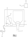
- a further operational parameter which can be determined by the remote manager, is a liquid volume for the alternative embodiment shown in fig. 2 .
- the liquid volume of one shot can be determined for a liquid dispenser 1.
- a further operational parameter which can be determined by the remote manager, is an indicator preference.
- the device 1 can send a notification to the external server 6.
- Said predetermined percentage of the original amount is the indicator preference.
- the notification can be sent to the external server 6, when the battery state of charge is less than a predetermined value or other disturbances in the operation of device 1, such as, for example, a paper jam.
- the predetermined value of the battery state of charge is the indicator preference.
- One operational parameter can be easily combined with another operational parameter in order to improve the remote management of the device 1.
- a current state of the device 1 can be translated into a work parameter.
- the work parameter comprises for example a remaining quantity of liquid and sheet material 3, a charge status, an indicator status.
- the work parameter includes a remaining quantity of liquid and sheet material 3.
- the work parameter includes a current state of the device 1 representative of a charge status.
- the work parameter includes an indicator status.
- the indicator status can change which may be translated into a work parameter and be sent to the external server 6.
- Processor 7 is provided further for the purpose of controlling the current state of the device 1, which can be determined by the work parameter, such as a remaining quantity of liquid and sheet material 3, a charge status, an indicator status. Processor 7 is provided further for the purpose of comparing the latest work parameter stored in the non-volatile memory 4 with the obtained work parameter. When processor 7 establishes that the obtained work parameter does not correspond to the latest work parameter stored in the non-volatile memory 4, processor 7 sends the obtained work parameter to the non-volatile memory 4 and to the external server 6 via the communication module 5. The remote manager can be notified via the external server 6 about the current state of the device land a maintenance of the device 1 can be scheduled.
- the work parameter such as a remaining quantity of liquid and sheet material 3, a charge status, an indicator status.
- Processor 7 is provided further for the purpose of comparing the latest work parameter stored in the non-volatile memory 4 with the obtained work parameter.
- processor 7 sends the obtained work parameter to the non-volatile memory 4 and to the external server 6 via
- the dispenser lean be powered by direct connection to the electricity grid via a power source connection 8.
- the dispenser 1 an be powered by any suitable type and sizes of batteries, for example, selected from the group consisting of alkaline, NiMH, AA, AAA, C and D.
- the dispenser is a liquid dispenser 1.
- the dispensing mechanism 2 can be a pump (fluid to fluid), can be a spray or atomizer (liquid to small liquid particles or mist) or can be a foamer (liquid to foam).
- the dispensing mechanism 2 is provided with a liquid at an input side, and discrete charges of the liquid are emitted (whether or not the emitted liquid has been transformed into foam or mist).
- the device of figure 2 is similar in use and structure as the device described above in relation to figure 1 .
- the device of figure 1 is a dispenser for sheet material whereas the device of figure 2 is a dispenser for a liquid.
- Figure 3 is a flowchart illustrating the operation of dispenser 1 comprising a dispensing mechanism 2 for dispensing a predetermined quantity of at least one of liquid and sheet material 3 according to an embodiment of the present disclosure.
- the remote manager installs specific operating settings for the dispenser 1.
- Said specific operating settings characterize the operation of the device and comprise at least a dispenser status and optionally also at least one operational parameter.
- the dispenser status can be a first dispenser status or a second dispenser status.
- the non-volatile memory 4 is empty and the processor retrieves the dispenser status from a remote server via the communication module and write the received dispenser status into the non-volatile memory 4.
- the processor 7 retrieves the dispenser status from the external server 6 via the communication module 5.
- the processor 7 compares the latest dispenser status stored in the non-volatile memory 4 with the received dispenser status, if the dispenser status is already stored in the non-volatile memory 4.
- processor 7 sends the received dispenser status to the non-volatile memory 4.
- the dispenser status stored in the non-volatile memory can be chosen from at least a first dispenser status and a second dispenser status.
- the first dispenser status relates to an inactive or OFF status of the dispenser.
- the second dispenser status relates to an active or ON status of the dispenser. Intermediate statuses where the operational activities of the dispenser are limited are also possible.
- the processor described hereunder, is adapted to retrieve the dispenser status from the non-volatile memory before operating the dispenser. This allows the processor to operate the dispenser in accordance with the dispenser status. In other words, in an embodiment, the processor only operates the dispenser when it is in the active or ON status.
- the processor 7 When the received dispenser status is the first dispenser status, the processor 7 operates the dispensing mechanism 2 in order to disable the dispensing mechanism 2. The processor 7 sends a stop signal to the dispensing mechanism.
- the processor 7 When the received dispenser status is the second dispenser status, the processor 7 operates the dispensing mechanism 2 in order to enable the dispensing mechanism 2. The processor 7 sends a start signal to the dispensing mechanism.
- the processor 7 When the dispenser 1 is in the second status, the processor 7 periodically communicates with the external server 6 via the communication module 5 to receive the update of the dispenser status. In this status, the dispensing mechanism 2 is operated and can be used.
- the dispensing mechanism 2 can be operated by a button placed on an outer side of dispenser 1 such that a user can operate the button in simple manner.
- a proximity sensor can also be provided such that a user can operate dispensing mechanism 2 by moving into the vicinity of proximity sensor.
- the button and/or the sensor is preferably electrically connected to the dispensing mechanism 2 via the processor 7.
- the processor 7 When the processor 7 indicates that the button was pushed by the user, it accesses the non-volatile memory 4 to request the latest dispenser status and optionally also the operational parameter stored in the non-volatile memory 4.
- the dispenser status handled as explained above. Only when the dispenser status is in the ON or enabled state, further steps are executed.
- the processor 7 receives the operational parameter, such as predetermined quantity of liquid and sheet material 3, a working timeslot, a working mode, a sheet length, a liquid volume, an indicator preference, processor 7 controls the current state of the device 1.
- the processor 7 operates the dispensing mechanism 2 accordingly to the received operational parameter.
- the work parameter such as a remaining quantity of liquid and sheet material 3, a charge status, an indicator status
- the processor 7 sends the determined work parameter to a memory, for example to the non-volatile memory 4, and preferably also to the external server 6 via the communication module 5.
- the remote manager can be notified via the external server 6 about the current state of the device land a maintenance of the device 1 can be scheduled.
Landscapes
- Health & Medical Sciences (AREA)
- Public Health (AREA)
- Devices For Dispensing Beverages (AREA)
- Loading And Unloading Of Fuel Tanks Or Ships (AREA)
- Containers And Packaging Bodies Having A Special Means To Remove Contents (AREA)
- Medical Preparation Storing Or Oral Administration Devices (AREA)
Claims (13)
- Verfahren zum Betreiben einer Ausgabevorrichtung (1), umfassend einen Ausgabemechanismus (2) zum Ausgeben einer zuvor bestimmten Menge von mindestens einem von einer Flüssigkeit und einem Blattmaterial (3), das Verfahren umfassend:- Abrufen eines Ausgabevorrichtungsstatus;- Speichern des Ausgabevorrichtungsstatus in einem nichtflüchtigen Speicher (4) der Ausgabevorrichtung (1); und- Betreiben des Ausgabemechanismus (2) basierend auf dem Ausgabevorrichtungsstatus,- wobei der Schritt des Betreibens ein Deaktivieren des Ausgabemechanismus (2) umfasst, wenn der Ausgabevorrichtungsstatus ein erster Status ist, und- wobei der Schritt des Betreibens ein Aktivieren des Ausgabemechanismus (2) umfasst, wenn der Ausgabevorrichtungsstatus ein zweiter Status ist.
- Verfahren nach Anspruch 1, wobei der Schritt des Abrufens ein Kommunizieren mit einem externen Server (6) über ein Kommunikationsmodul (5) umfasst, um den Ausgabevorrichtungsstatus zu empfangen.
- Verfahren nach Anspruch 2, ferner umfassend, wenn sich die Ausgabevorrichtung (1) in dem ersten Status befindet, ein periodisches Kommunizieren mit dem externen Server (6) über das Kommunikationsmodul (5), um den Ausgabevorrichtungsstatus zu aktualisieren.
- Verfahren nach Anspruch 1, ferner umfassend, wenn sich die Ausgabevorrichtung (1) in dem zweiten Status befindet, das periodische Kommunizieren mit dem externen Server (6) über das Kommunikationsmodul (5), um den Ausgabevorrichtungsstatus zu aktualisieren.
- Verfahren nach einem der vorstehenden Ansprüche, wobei ein Betriebsparameter von dem externen Server (6) empfangen wird und wobei der Schritt des Betreibens des Ausgabemechanismus (2) zusätzlich auf dem Betriebsparameter basiert.
- Verfahren nach einem der vorstehenden Ansprüche, wobei der Betriebsparameter mindestens die zuvor bestimmte Menge, ein Arbeitszeitfenster, einen Arbeitsmodus, eine Blattlänge, ein Flüssigkeitsvolumen, eine Anzeigepräferenz umfasst.
- Verfahren nach einem der vorstehenden Ansprüche, wobei das Verfahren ferner den Schritt eines Übertragens eines Arbeitsparameters an den externen Server (6) über das Kommunikationsmodul (5) umfasst.
- Verfahren nach einem der vorstehenden Ansprüche, wobei der Arbeitsparameter mindestens eine verbleibende Menge an Flüssigkeit und Blattmaterial (3), einen Ladestatus, einen Anzeigestatus umfasst.
- Verfahren nach Anspruch 1, wobei das flüssige Material eine flüssige Seife ist.
- Verfahren nach Anspruch 1, wobei das Blattmaterial ein Papier ist.
- Ausgabevorrichtung (1), umfassend einen Ausgabemechanismus (2) zum Ausgeben einer zuvor bestimmten Menge von mindestens einem von der Flüssigkeit und dem Blattmaterial (3), die Ausgabevorrichtung (1) ferner umfassend einen Prozessor (7) und einen nichtflüchtigen Speicher (4), wobei die Ausgabevorrichtung (1) dadurch gekennzeichnet ist, dass der Prozessor (7) mit dem nichtflüchtigen Speicher (4) zum Speichern mindestens eines Ausgabevorrichtungsstatus betriebsfähig verbunden ist,- wobei der Prozessor (7) konfiguriert ist, um den Ausgabemechanismus (2) basierend auf dem Ausgabevorrichtungsstatus zu betreiben, und- wobei der Prozessor (7) zum Senden eines Stoppsignals an den Ausgabemechanismus (2) bereitgestellt ist, wenn der Ausgabevorrichtungsstatus ein erster Status ist, und- wobei der Prozessor (7) zum Senden eines Startsignals an den Ausgabemechanismus (2) bereitgestellt ist, wenn der Ausgabevorrichtungsstatus ein zweiter Status ist.
- Ausgabevorrichtung (1) nach dem vorstehenden Anspruch, ferner umfassend ein Kommunikationsmodul (5), wobei der Prozessor (7) mit dem Kommunikationsmodul (5) zum Kommunizieren mit einem externen Server (6), Empfangen eines Status, Aktualisieren des Ausgabevorrichtungsstatus in dem nichtflüchtigen Speicher (4), basierend auf dem empfangenen Status, betriebsfähig verbunden ist.
- Ausgabevorrichtung (1) nach Anspruch 11 oder 12, wobei der Prozessor (7) konfiguriert ist, um die Ausgabevorrichtung (1) nach dem Verfahren nach einem der Ansprüche 1 bis 10 zu betreiben.
Priority Applications (6)
| Application Number | Priority Date | Filing Date | Title |
|---|---|---|---|
| HUE21167906A HUE069216T2 (hu) | 2021-04-12 | 2021-04-12 | Adagoló |
| PL21167906.3T PL4074232T3 (pl) | 2021-04-12 | 2021-04-12 | Dozownik |
| ES21167906T ES3007561T3 (en) | 2021-04-12 | 2021-04-12 | Dispenser |
| EP21167906.3A EP4074232B1 (de) | 2021-04-12 | 2021-04-12 | Spender |
| RS20241389A RS66308B1 (sr) | 2021-04-12 | 2021-04-12 | Dispenzer |
| HRP20241691TT HRP20241691T1 (hr) | 2021-04-12 | 2021-04-12 | Dozator |
Applications Claiming Priority (1)
| Application Number | Priority Date | Filing Date | Title |
|---|---|---|---|
| EP21167906.3A EP4074232B1 (de) | 2021-04-12 | 2021-04-12 | Spender |
Publications (3)
| Publication Number | Publication Date |
|---|---|
| EP4074232A1 EP4074232A1 (de) | 2022-10-19 |
| EP4074232C0 EP4074232C0 (de) | 2024-10-30 |
| EP4074232B1 true EP4074232B1 (de) | 2024-10-30 |
Family
ID=75477970
Family Applications (1)
| Application Number | Title | Priority Date | Filing Date |
|---|---|---|---|
| EP21167906.3A Active EP4074232B1 (de) | 2021-04-12 | 2021-04-12 | Spender |
Country Status (6)
| Country | Link |
|---|---|
| EP (1) | EP4074232B1 (de) |
| ES (1) | ES3007561T3 (de) |
| HR (1) | HRP20241691T1 (de) |
| HU (1) | HUE069216T2 (de) |
| PL (1) | PL4074232T3 (de) |
| RS (1) | RS66308B1 (de) |
Family Cites Families (5)
| Publication number | Priority date | Publication date | Assignee | Title |
|---|---|---|---|---|
| US20090125424A1 (en) * | 2007-11-14 | 2009-05-14 | Wegelin Jackson W | Method and device for indicating future need for product replacement of random use dispensing |
| EP2033555B1 (de) * | 2007-09-10 | 2016-02-24 | Oro Clean Chemie AG | Automatischer Fluid-Dispenser |
| EP2873357A1 (de) | 2013-11-15 | 2015-05-20 | Hygiene Vision Europe BVBA | Spender |
| US9830764B1 (en) * | 2014-04-09 | 2017-11-28 | Gpcp Ip Holdings Llc | Universal dispenser interface |
| US10359744B2 (en) * | 2015-01-28 | 2019-07-23 | GOJO Indutries, Inc. | System and method for programming a setting of a fluid dispenser |
-
2021
- 2021-04-12 HR HRP20241691TT patent/HRP20241691T1/hr unknown
- 2021-04-12 ES ES21167906T patent/ES3007561T3/es active Active
- 2021-04-12 HU HUE21167906A patent/HUE069216T2/hu unknown
- 2021-04-12 PL PL21167906.3T patent/PL4074232T3/pl unknown
- 2021-04-12 EP EP21167906.3A patent/EP4074232B1/de active Active
- 2021-04-12 RS RS20241389A patent/RS66308B1/sr unknown
Also Published As
| Publication number | Publication date |
|---|---|
| HRP20241691T1 (hr) | 2025-02-14 |
| EP4074232A1 (de) | 2022-10-19 |
| HUE069216T2 (hu) | 2025-02-28 |
| EP4074232C0 (de) | 2024-10-30 |
| RS66308B1 (sr) | 2025-01-31 |
| ES3007561T3 (en) | 2025-03-20 |
| PL4074232T3 (pl) | 2025-01-20 |
Similar Documents
| Publication | Publication Date | Title |
|---|---|---|
| EP3080759B1 (de) | Verfahren zur bestimmung von ressourcennutzungsdaten für eine anlage, datensammelvorrichtung, datensammelsystem und datensammelverfahren | |
| EP3905935B1 (de) | Leistungsverwaltungssystem für spender | |
| EP2768366B1 (de) | Produktfüllstandssensor für einen produktspender | |
| US7044421B1 (en) | Electronically controlled roll towel dispenser with data communication system | |
| US10929794B2 (en) | Dispensing system | |
| US20240412139A1 (en) | Management of Washroom Components | |
| KR20140090204A (ko) | 핸즈 프리 디스펜서의 동력 소모를 관리하기 위한 방법 | |
| EP1202924B1 (de) | Elektronisch gesteuerter spender für aufgerollte handtücher | |
| BRPI1000738A2 (pt) | dispensador acionado sem fio para dispensar material de um recipiente de recarga | |
| US20220215339A1 (en) | Automatic household consumable product inventory tracking and re-order devices, systems, and methods | |
| US11214456B2 (en) | Method and arrangement for detecting a filling level in a tissue dispenser | |
| EP4074232B1 (de) | Spender | |
| KR101777727B1 (ko) | 공중화장실용 종이타월 자동배출장치 및 관리 시스템 | |
| KR101805702B1 (ko) | 공중화장실용 화장지 자동배출장치 및 관리 시스템 | |
| EP4212073B1 (de) | Modulare badezimmervorrichtung, badezimmerverwaltungssystem und badezimmerverwaltungsverfahren | |
| KR101801219B1 (ko) | 공중화장실용 손세정제 자동배출장치 및 관리 시스템 | |
| US20200329927A1 (en) | Automatic toilet seat cover dispensers and methods of using the same | |
| GB2392439A (en) | Programmable dispenser | |
| EP2060683A2 (de) | Automatisiertes Spülsystem | |
| US20240349954A1 (en) | Systems and methods for predicting system use and calibrating the predictions | |
| KR102562532B1 (ko) | 분배 시스템 | |
| EP4450389A2 (de) | Systeme und verfahren zur vorhersage der systemverwendung und kalibrierung der vorhersage | |
| BR112020023457B1 (pt) | Sistema de gerenciamento de banheiro, e, métodos | |
| CN116456877A (zh) | 具有改进性能的分配装置 |
Legal Events
| Date | Code | Title | Description |
|---|---|---|---|
| REG | Reference to a national code |
Ref country code: HR Ref legal event code: TUEP Ref document number: P20241691T Country of ref document: HR |
|
| PUAI | Public reference made under article 153(3) epc to a published international application that has entered the european phase |
Free format text: ORIGINAL CODE: 0009012 |
|
| STAA | Information on the status of an ep patent application or granted ep patent |
Free format text: STATUS: THE APPLICATION HAS BEEN PUBLISHED |
|
| AK | Designated contracting states |
Kind code of ref document: A1 Designated state(s): AL AT BE BG CH CY CZ DE DK EE ES FI FR GB GR HR HU IE IS IT LI LT LU LV MC MK MT NL NO PL PT RO RS SE SI SK SM TR |
|
| STAA | Information on the status of an ep patent application or granted ep patent |
Free format text: STATUS: REQUEST FOR EXAMINATION WAS MADE |
|
| 17P | Request for examination filed |
Effective date: 20230419 |
|
| RBV | Designated contracting states (corrected) |
Designated state(s): AL AT BE BG CH CY CZ DE DK EE ES FI FR GB GR HR HU IE IS IT LI LT LU LV MC MK MT NL NO PL PT RO RS SE SI SK SM TR |
|
| RIN1 | Information on inventor provided before grant (corrected) |
Inventor name: KRAJACIC, ALEN Inventor name: KISAK, KRUNOSLAV |
|
| GRAP | Despatch of communication of intention to grant a patent |
Free format text: ORIGINAL CODE: EPIDOSNIGR1 |
|
| STAA | Information on the status of an ep patent application or granted ep patent |
Free format text: STATUS: GRANT OF PATENT IS INTENDED |
|
| INTG | Intention to grant announced |
Effective date: 20240531 |
|
| GRAS | Grant fee paid |
Free format text: ORIGINAL CODE: EPIDOSNIGR3 |
|
| GRAA | (expected) grant |
Free format text: ORIGINAL CODE: 0009210 |
|
| STAA | Information on the status of an ep patent application or granted ep patent |
Free format text: STATUS: THE PATENT HAS BEEN GRANTED |
|
| AK | Designated contracting states |
Kind code of ref document: B1 Designated state(s): AL AT BE BG CH CY CZ DE DK EE ES FI FR GB GR HR HU IE IS IT LI LT LU LV MC MK MT NL NO PL PT RO RS SE SI SK SM TR |
|
| REG | Reference to a national code |
Ref country code: GB Ref legal event code: FG4D |
|
| REG | Reference to a national code |
Ref country code: CH Ref legal event code: EP |
|
| REG | Reference to a national code |
Ref country code: IE Ref legal event code: FG4D |
|
| REG | Reference to a national code |
Ref country code: DE Ref legal event code: R096 Ref document number: 602021020858 Country of ref document: DE |
|
| U01 | Request for unitary effect filed |
Effective date: 20241129 |
|
| U07 | Unitary effect registered |
Designated state(s): AT BE BG DE DK EE FI FR IT LT LU LV MT NL PT RO SE SI Effective date: 20241210 |
|
| REG | Reference to a national code |
Ref country code: GR Ref legal event code: EP Ref document number: 20240402856 Country of ref document: GR Effective date: 20250120 |
|
| REG | Reference to a national code |
Ref country code: SK Ref legal event code: T3 Ref document number: E 45575 Country of ref document: SK |
|
| REG | Reference to a national code |
Ref country code: HR Ref legal event code: T1PR Ref document number: P20241691 Country of ref document: HR |
|
| REG | Reference to a national code |
Ref country code: HU Ref legal event code: AG4A Ref document number: E069216 Country of ref document: HU |
|
| REG | Reference to a national code |
Ref country code: ES Ref legal event code: FG2A Ref document number: 3007561 Country of ref document: ES Kind code of ref document: T3 Effective date: 20250320 |
|
| PGFP | Annual fee paid to national office [announced via postgrant information from national office to epo] |
Ref country code: HR Payment date: 20250319 Year of fee payment: 5 |
|
| PGFP | Annual fee paid to national office [announced via postgrant information from national office to epo] |
Ref country code: CZ Payment date: 20250324 Year of fee payment: 5 |
|
| REG | Reference to a national code |
Ref country code: HR Ref legal event code: ODRP Ref document number: P20241691 Country of ref document: HR Payment date: 20250319 Year of fee payment: 5 |
|
| PGFP | Annual fee paid to national office [announced via postgrant information from national office to epo] |
Ref country code: SK Payment date: 20250318 Year of fee payment: 5 |
|
| PGFP | Annual fee paid to national office [announced via postgrant information from national office to epo] |
Ref country code: RS Payment date: 20250319 Year of fee payment: 5 |
|
| PGFP | Annual fee paid to national office [announced via postgrant information from national office to epo] |
Ref country code: TR Payment date: 20250327 Year of fee payment: 5 |
|
| U20 | Renewal fee for the european patent with unitary effect paid |
Year of fee payment: 5 Effective date: 20250428 |
|
| PG25 | Lapsed in a contracting state [announced via postgrant information from national office to epo] |
Ref country code: SM Free format text: LAPSE BECAUSE OF FAILURE TO SUBMIT A TRANSLATION OF THE DESCRIPTION OR TO PAY THE FEE WITHIN THE PRESCRIBED TIME-LIMIT Effective date: 20241030 |
|
| PGFP | Annual fee paid to national office [announced via postgrant information from national office to epo] |
Ref country code: MC Payment date: 20250403 Year of fee payment: 5 |
|
| PGFP | Annual fee paid to national office [announced via postgrant information from national office to epo] |
Ref country code: PL Payment date: 20250405 Year of fee payment: 5 |
|
| PGFP | Annual fee paid to national office [announced via postgrant information from national office to epo] |
Ref country code: GB Payment date: 20250428 Year of fee payment: 5 Ref country code: ES Payment date: 20250505 Year of fee payment: 5 |
|
| PGFP | Annual fee paid to national office [announced via postgrant information from national office to epo] |
Ref country code: IS Payment date: 20250414 Year of fee payment: 5 Ref country code: HU Payment date: 20250326 Year of fee payment: 5 Ref country code: NO Payment date: 20250429 Year of fee payment: 5 |
|
| PGFP | Annual fee paid to national office [announced via postgrant information from national office to epo] |
Ref country code: GR Payment date: 20250430 Year of fee payment: 5 |
|
| PGFP | Annual fee paid to national office [announced via postgrant information from national office to epo] |
Ref country code: CH Payment date: 20250501 Year of fee payment: 5 |
|
| PGFP | Annual fee paid to national office [announced via postgrant information from national office to epo] |
Ref country code: IE Payment date: 20250428 Year of fee payment: 5 |
|
| PLBE | No opposition filed within time limit |
Free format text: ORIGINAL CODE: 0009261 |
|
| STAA | Information on the status of an ep patent application or granted ep patent |
Free format text: STATUS: NO OPPOSITION FILED WITHIN TIME LIMIT |
|
| 26N | No opposition filed |
Effective date: 20250731 |