EP4074161B1 - Heuwerbungsmaschine mit fangelement - Google Patents
Heuwerbungsmaschine mit fangelement Download PDFInfo
- Publication number
- EP4074161B1 EP4074161B1 EP22167275.1A EP22167275A EP4074161B1 EP 4074161 B1 EP4074161 B1 EP 4074161B1 EP 22167275 A EP22167275 A EP 22167275A EP 4074161 B1 EP4074161 B1 EP 4074161B1
- Authority
- EP
- European Patent Office
- Prior art keywords
- support arm
- haymaking machine
- retaining element
- frame
- base part
- Prior art date
- Legal status (The legal status is an assumption and is not a legal conclusion. Google has not performed a legal analysis and makes no representation as to the accuracy of the status listed.)
- Active
Links
Images



Classifications
-
- A—HUMAN NECESSITIES
- A01—AGRICULTURE; FORESTRY; ANIMAL HUSBANDRY; HUNTING; TRAPPING; FISHING
- A01D—HARVESTING; MOWING
- A01D78/00—Haymakers with tines moving with respect to the machine
- A01D78/08—Haymakers with tines moving with respect to the machine with tine-carrying rotary heads or wheels
- A01D78/10—Haymakers with tines moving with respect to the machine with tine-carrying rotary heads or wheels the tines rotating about a substantially vertical axis
- A01D78/1071—Having only one rotor
-
- A—HUMAN NECESSITIES
- A01—AGRICULTURE; FORESTRY; ANIMAL HUSBANDRY; HUNTING; TRAPPING; FISHING
- A01D—HARVESTING; MOWING
- A01D78/00—Haymakers with tines moving with respect to the machine
- A01D78/08—Haymakers with tines moving with respect to the machine with tine-carrying rotary heads or wheels
- A01D78/10—Haymakers with tines moving with respect to the machine with tine-carrying rotary heads or wheels the tines rotating about a substantially vertical axis
- A01D78/1028—Pivotable rotor support arms
-
- A—HUMAN NECESSITIES
- A01—AGRICULTURE; FORESTRY; ANIMAL HUSBANDRY; HUNTING; TRAPPING; FISHING
- A01D—HARVESTING; MOWING
- A01D78/00—Haymakers with tines moving with respect to the machine
- A01D78/08—Haymakers with tines moving with respect to the machine with tine-carrying rotary heads or wheels
- A01D78/10—Haymakers with tines moving with respect to the machine with tine-carrying rotary heads or wheels the tines rotating about a substantially vertical axis
-
- A—HUMAN NECESSITIES
- A01—AGRICULTURE; FORESTRY; ANIMAL HUSBANDRY; HUNTING; TRAPPING; FISHING
- A01D—HARVESTING; MOWING
- A01D78/00—Haymakers with tines moving with respect to the machine
- A01D78/08—Haymakers with tines moving with respect to the machine with tine-carrying rotary heads or wheels
- A01D78/10—Haymakers with tines moving with respect to the machine with tine-carrying rotary heads or wheels the tines rotating about a substantially vertical axis
- A01D78/1007—Arrangements to facilitate transportation specially adapted therefor
- A01D78/1014—Folding frames
-
- A—HUMAN NECESSITIES
- A01—AGRICULTURE; FORESTRY; ANIMAL HUSBANDRY; HUNTING; TRAPPING; FISHING
- A01D—HARVESTING; MOWING
- A01D78/00—Haymakers with tines moving with respect to the machine
- A01D78/08—Haymakers with tines moving with respect to the machine with tine-carrying rotary heads or wheels
- A01D78/10—Haymakers with tines moving with respect to the machine with tine-carrying rotary heads or wheels the tines rotating about a substantially vertical axis
- A01D78/1021—Telescopic frames
-
- A—HUMAN NECESSITIES
- A01—AGRICULTURE; FORESTRY; ANIMAL HUSBANDRY; HUNTING; TRAPPING; FISHING
- A01D—HARVESTING; MOWING
- A01D80/00—Parts or details of, or accessories for, haymakers
Definitions
- the present invention relates to a haymaking machine according to the preamble of claim 1.
- Haymaking machines such as tedders or rakes are used in agriculture to turn (or teed) cut grass or hay in the field and/or gather it into swaths.
- a common type of haymaking machine uses one or more rotating rakes, each of which has a plurality of tine arms rotating around a common axis. Each tine arm has a plurality of tines at the end, which can be guided over the field close to the ground and in doing so catch the stalks. The caught stalks are carried along by the tines for a certain distance before they are thrown off or raised and land again on the field at another location.
- at least one collecting element e.g.
- a baffle cloth is often provided, which can be arranged in an active position radially outside the path of movement of the tines.
- the catcher element runs approximately vertically in the active position, it is connected to the frame of the haymaking machine via a support arm, which runs approximately horizontally and can be connected to the frame, for example, near the axis of rotation of the rotary rake.
- the support arm is usually also connected to a bracket-like rotary guard, which is arranged radially outside and above the path of movement of the rotary rake in the active position in order to prevent the rotating tines from colliding with other objects.
- the publication DE 692 07 987 T2 discloses a haymaking machine with a hydraulic cylinder which is located above a rake wheel and which is connected to an adjusting rod in such a way that it can move it in order to change the position of a swath former.
- the haymaking machine is further provided with means for pivoting the swath former when it is adjusted by means of the hydraulic cylinder.
- the publication DE 26 45 127 A1 discloses a haymaking machine with two rotors arranged side by side, which can be adjusted to a position in which they convey the hay between them to the rear, and to a position in which they convey the hay along their front side and lay it on a swath on an outer side next to the rear rotor.
- the publication DE 20 2009 003 439 U1 discloses a haymaking machine with an impact element for crops, wherein the impact element is held in a substantially upright orientation when moved from a lowered working position to a raised transport position and/or vice versa.
- the object of the invention is to propose a reliable and simplified adjusting mechanism for a catching element of a rake gyro.
- a haymaking machine is created, with a rake and a catching element associated therewith, which is connected to a frame via a support arm, wherein a base part of the support arm is pivotally connected to the frame about a support arm axis in order to pivot the support arm between a lowered active position and a raised passive position, and a sliding part to which the catching element is connected is displaceable relative to the base part between an inner position and an outer position further away from the support arm axis in order to effect a length adjustment of the support arm.
- the haymaking machine is generally designed to collect, turn, distribute and/or windrow stalks such as grass or hay in a field. It can be designed in particular to be pulled by a tractor.
- a frame of the haymaking machine can be coupled to the tractor via a drawbar.
- At least one rotary rake, often a plurality of rotary rakes, is arranged on the frame. Each rotary rake can be rotated about an upward, but not necessarily vertical, rotation axis or rotary axis relative to the frame.
- the drive force for the rotation can be transmitted from the tractor, e.g. via a power take-off shaft.
- the rotary rake usually has a plurality of tine arms that protrude outwards from the rotary axis.
- Each tine arm in turn carries a number of tines with which the stalk material is grasped.
- the tine arm or a part of the tine arm to which the tines are connected can be pivoted about its longitudinal axis so that the tines can be pivoted alternately into a position close to the ground and into a position away from the ground.
- a catching element is assigned to the (or at least one) rake.
- the catching element can be designed, for example, as a rigid plate or grid or, in particular, as a flexible catching cloth or swath cloth. Its function is to limit the movement space of the stalk material that is caught by the rake and thrown up or away. This means that the stalk material hits the catching element and falls to the ground near it. This means that a swath can be laid near the catching element, for example.
- the catching element is connected to the frame via a support arm, i.e. the support arm forms the connection or suspension of the catching element in relation to the frame.
- a base part of the support arm is connected to the frame so that it can pivot about a support arm axis in order to pivot the support arm between a lowered active position and a raised passive position.
- the support arm axis does not run vertically, but rather horizontally or at a slight angle (less than 30°) to the horizontal.
- the support arm can either be lowered into an active position, in which it can run horizontally, for example, and in which the catching element is positioned close to the ground, or raised into a passive position, in which the catching element is (significantly) raised from the ground.
- the base part can have a rotary guard for the rake, which can be pivoted together with the base part.
- the rotary guard can be designed as a bracket, for example, and is used to prevent a collision between the rotating rake and other objects.
- a sliding part, to which the catch element is connected, is adjustable relative to the base part between an inner position and a position further away from the The sliding part is part of the support arm and can be moved in a translational manner relative to the base part.
- the base part can have a hollow profile in which the sliding part is partially accommodated in order to enable a telescopic movement. By moving the sliding part, the length of the support arm is adjusted.
- the sliding part can be moved into the inner position and the support arm can be pivoted into the passive position by means of a linear drive acting between the frame and the sliding part, with a retaining mechanism being designed to hold the support arm in the active position until the sliding part has reached the inner position.
- the linear drive acts between the frame and the sliding part, and is at least designed to generate a tensile force and pull the sliding part towards the frame. This initially results in the sliding part being adjusted to the inner position, or one could also say that the sliding part is retracted with the catch element arranged on it.
- the tensile force also causes the support arm to pivot upwards into the passive position.
- the linear drive (or the connecting line of its points of application on the frame and the sliding part) is aligned non-radially with respect to the support arm axis.
- the linear drive can be connected to the frame via a drive swivel axis, which is arranged above the support arm axis and above the base part.
- the drive swivel axis should also be offset horizontally from the support arm axis, on a side opposite the catch element.
- the linear drive can in particular be designed as a cylinder or have a cylinder, e.g. a hydraulic, electro-hydraulic or pneumatic cylinder.
- the retention mechanism is which holds the support arm in the active position until the sliding part has reached the inner position. This means that while the sliding part is in the outer position or between the outer and inner positions, the support arm is effectively locked in the active position. This prevents the support arm from pivoting unintentionally and the associated lifting of the catch element from the ground during the length adjustment of the support arm.
- the retaining mechanism releases the support arm so that it can be pivoted into the passive position.
- the pivoting of the support arm into the passive position is therefore causally linked via the retaining mechanism to the fact that the sliding part has reached the inner position.
- the linear drive can generally also exert a compressive force opposite to the tensile force mentioned above, by means of which the support arm can be pivoted from the passive position into the active position and the sliding part can be adjusted towards the outer position, i.e. extended.
- the retaining mechanism has a retaining element that is adjustably arranged on the frame and that engages the base part in a locking position and releases it in a release position.
- the retaining element can in particular be designed as a single piece.
- the retaining element is adjustable at least between the aforementioned locking position and the release position. Normally, the retaining element in the locking position creates a positive connection with the base part, whereby the latter is held back or locked relative to the frame. Additionally or alternatively, the retaining element can also create a force connection with the base part.
- the base part can interact indirectly or directly mechanically with the retaining element.
- the retaining element is advantageously arranged on the frame so that it can pivot. This means that it can pivot between the locking position and the release position.
- the pivoting adjustment has the advantage that it only requires a pivot bearing instead of, for example, a guide rail or the like, which would be required for a translational adjustment.
- the retaining element can advantageously be connected to the frame via a first spring element, which urges the retaining element towards the locking position. This means that, provided no other forces act on the retaining element, it is held in the locking position or moved into it by the first spring element. This also ensures that the support arm is reliably locked.
- the first spring element can be designed as a torsion spring or a tension spring, for example. When the inner position is approached, the spring force of the first spring element is overcome by the direct or indirect action of the sliding part.
- the sliding part is advantageously designed to act directly on the retaining element when approaching the inner position and to push it out of the locking position. This keeps the entire mechanism simple, since there are no intermediate elements for transmitting force between the sliding part and the retaining element.
- a preferred embodiment provides that the retaining element is partially inserted into a recess in the base part in the locking position, with a retaining section of the retaining element engaging behind an edge section of the base part formed on the edge of the recess.
- the base part can have, for example, a hollow profile within which the sliding part is also guided displaceably.
- the recess can be an opening or cutout in a Wall of the hollow profile.
- the retaining element is partially inserted into this recess in the locking position.
- An edge section is formed on the edge of the recess, behind which the retaining element engages with a retaining section.
- the retaining section and the edge section thus create a positive connection between the retaining element and the base part, which leads to locking.
- the retaining section is normally formed as a projection on the retaining element.
- the retaining element advantageously has a ramp section with which the base part interacts when approaching the active position in order to push the retaining element out of the locking position.
- the displacement of the retaining element can in particular enable insertion into the recess in the base part.
- the ramp section is bevelled in relation to the direction of movement of the base part in such a way that the interaction results in a force deflection which displaces the retaining element.
- the base part and the ramp section slide along one another.
- the above-mentioned edge section and the ramp section can interact with one another.
- edge section initially pushes the retaining element out of the retaining position by interacting with the ramp section so that it can be inserted into the recess before it returns to the retaining position in which the retaining section engages behind the edge section.
- the sliding part can also interact with the ramp section when approaching the inner position in order to push the retaining element out of the retaining position.
- the locking mechanism prevents the support arm from pivoting upwards before the sliding part is retracted, it cannot usually prevent the sliding part from being extended before the support arm has pivoted downwards from the passive position into the active position.
- this is counteracted by the base part being connected to the frame via a second spring element, which urges the base part towards the active position.
- the second spring element generates a torque in the direction of the active position, so that the downward pivoting of the support arm. It can be designed as a torsion spring or a tension spring, for example.
- the strength of the second spring element can be selected in relation to the strength of the linear drive so that pivoting into the passive position is only slightly hindered.
- Fig. 1 shows a haymaking machine 1, in this case a rotary swather, according to the present invention.
- a rotary rake 2 is mounted on a frame 5 so as to be rotatable about a rotation axis or rotary axis K.
- the rotary axis K runs vertically in this example, but could also be inclined relative to the vertical.
- the rotary rake 2 has a plurality of tine arms 3, each of which in turn carries a plurality of tines 4.
- each tine arm 3 can be pivoted about its longitudinal axis, so that in the course of a rotation about the rotary axis K, the tines 4 are alternately pivoted between an approximately vertical position and an approximately horizontal position. In the approximately vertical position, which in Fig.
- the tines 4 are guided close to the ground so that they catch the crop on the ground, more precisely stalks such as grass or hay, and carry them along in accordance with the rotation of the rotary rake 2.
- the haymaking machine 1 has a catching element 10, which in this case is designed as a swath cloth.
- the catching element 10 In the Fig. 1 In the position shown, the catching element 10 extends vertically, outside the rotation area of the rotary rake 2. Due to its closed, flat shape, the catching element 10 catches crops so that they can be laid in a swath at a defined position. Details of the functioning of the haymaking machine are explained below, particularly with reference to the detailed view in Fig.2 explained and with reference to the sectional views in Fig. 3-5 , where the cutting plane is parallel to the drawing plane in Fig. 2 runs.
- the catch element 10 is connected to the frame 5 via a support arm 11.
- the support arm 11 has a base part 12 which is connected to the frame 5 so as to be pivotable about a horizontal support arm axis A, and a sliding part 13 which is displaceable above the base part 12 between an inner position (which is in Fig. 1 shown) and an outer position further away from the support arm axis A.
- This allows the catch element 10 to be positioned at different distances from the rotor axis K and a swath width can be changed.
- Due to the pivoting of the base part 12, the support arm 11 can be moved between a Fig. 1 - 4 shown, lowered active position and one in Fig.
- Both the movement of the sliding part 13 and the movement of the support arm 11 are effected by a hydraulic cylinder 6 acting as a linear drive.
- the hydraulic cylinder 6 is connected to the frame 5 via a drive pivot axis B.
- the drive pivot axis B runs parallel to the support arm axis A, but is offset both vertically and horizontally from it, as can be seen in particular in Fig. 2 - 5 can be seen.
- the hydraulic cylinder 6 has a cylinder housing 15 with an interior 16 and a piston rod unit 17 that can be moved relative to it. While the cylinder housing 15 is connected to the frame 5 via the drive pivot axis B, the piston rod unit 17 is connected to the sliding part 13 and the catch element 10.
- a force can be generated between the cylinder housing 15 and the piston rod unit 17.
- this force acts to move the sliding part 13 relative to the base part 12, and on the other hand, it generates a torque about the support arm axis A, which acts to pivot the support arm 11.
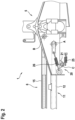
- a retaining mechanism 20 is provided, with a retaining element 21 that is mounted on the frame 5 so that it can pivot about a retaining element pivot axis C. While the support arm 11 is in the active position and the sliding part 13 has not yet reached the inner position, the retaining element 21 is partially inserted into a recess 18 in the base part 12. A projecting retaining section 22 of the retaining element 21 engages behind an edge section 19 formed to the side of the recess 18.
- a first spring element 25 which is designed here as a helical spring, is arranged between the retaining element 21 and frame 5, whereby the retaining element 21 is moved in the direction of a Fig. 3 shown locking position. If the sliding part 13 is pulled towards the support arm axis A by the action of the hydraulic cylinder 6, the retaining element 21 initially remains in the locking position until the sliding part 13 reaches the inner position. When the inner position is reached, the sliding part 13 hits the retaining element 21 and pushes it, as in Fig. 4 shown, against the force of the first spring element 25 from the locking position into a release position. The sliding part 13 partially cooperates with a beveled ramp section 23 of the retaining element 21.
- the hydraulic cylinder 6 has an end position damping which ensures that the hydraulic fluid can leave the interior 16 less quickly or can enter it when the piston rod unit 17 is in the area of its end position, i.e. in the greatest possible proximity to the drive pivot axis B.
- the end position damping ensures that the pivoting of the support arm 11 takes place comparatively slowly, while the displacement of the displacement part 13 between the inner position and the outer position takes place comparatively quickly.
- the pivoting of the support arm 11 from the passive position back to the active position is carried out on the one hand by the hydraulic cylinder 6 and on the other hand by a second spring element 26, which is also designed as a helical spring and is located between the frame 5 and the base part 12 of the support arm 11.
- This second spring element 26 generates an additional torque that acts on the support arm 11 in the direction of the active position. This supports the pivoting into the active position and effectively prevents the sliding part 13 is adjusted in the direction of the outer position before the support arm 11 has reached the active position.
- the edge section 19 of the base part 12 interacts with the ramp section 23.
Landscapes
- Life Sciences & Earth Sciences (AREA)
- Environmental Sciences (AREA)
- Soil Working Implements (AREA)
Description
- Die vorliegende Erfindung betrifft eine Heuwerbungsmaschine nach dem Oberbegriff von Anspruch 1.
- Heuwerbungsmaschinen wie Zetter oder Schwader dienen in der Landwirtschaft dazu, geschnittenes Gras bzw. Heu auf dem Feld zu wenden (bzw. zu zetten) und/oder zu Schwaden zusammenzubringen. Ein gängiger Typ von Heuwerbungsmaschine verwendet einen oder mehrere rotierende Rechkreisel, bei denen jeweils eine Mehrzahl von Zinkenarmen um eine gemeinsame Achse rotiert. Jeder Zinkenarm trägt endseitig eine Mehrzahl von Zinken, die bodennah über das Feld geführt werden können und dabei das Halmgut erfassen. Das erfasste Halmgut wird über eine gewisse Wegstrecke von den Zinken mitgeführt, bevor es ab- bzw. hochgeschleudert wird und an anderer Stelle wieder auf dem Feld landet. Um den Ablageort wenigstens ungefähr zu kontrollieren, ist oftmals wenigstens ein Fangelement (z.B. ein Pralltuch) vorgesehen, das in einer Aktivposition radial außerhalb der Bewegungsbahn der Zinken angeordnet werden kann. Während das Fangelement in der Aktivposition in etwa senkrecht verläuft, ist es mit dem Rahmen der Heuwerbungsmaschine über einen Tragarm verbunden, der in etwa waagerecht verläuft und z.B. in der Nähe der Rotationsachse des Rechkreisels mit dem Rahmen verbunden sein kann. Mit dem Tragarm ist in der Regel auch ein z.B. bügelartiger Kreiselschutz verbunden, der in der Aktivposition radial außerhalb und oberhalb der Bewegungsbahn des Rechkreisels angeordnet ist, um Kollisionen der rotierenden Zinken mit anderen Objekten zu verhindern. Dabei ist es zum einen bekannt, den Tragarm mit dem Fangelement aufwärts in eine Passivposition zu schwenken, wenn das Fangelement nicht benötigt wird oder z.B. für eine Straßenfahrt die Breite der Heuwerbungsmaschine verringert werden muss. Zum anderen ist es bekannt, in der Aktivposition die Länge des Tragarms zu verstellen, diesen also ein- oder auszufahren, um so das Fangelement in unterschiedlicher radialer Entfernung von der Rotationsachse zu positionieren. Hierdurch kann z.B. die Breite eines gelegten Schwads variiert werden. Das Schwenken einerseits sowie das Ausfahren des Tragarms andererseits erfolgen heutzutage motorisch mittels zweier separater Antriebselemente, z.B. Hydraulikzylinder.
- Die Druckschrift
DE 692 07 987 T2 offenbart eine Heuwerbungsmaschine mit einem Hydraulikzylinder, der sich über einem Rechrad befindet, und der mit einer Verstellstange derart verbunden ist, dass er sie verschieben kann, um die Lage eines Schwadformers zu ändern. Die Heuwerbungsmaschine ist ferner mit Mitteln zum Verschwenken des Schwadformers versehen, wenn er mittels des Hydraulikzylinders verstellt wird. - Die Druckschrift
DE 26 45 127 A1 offenbart eine Heuwerbungsmaschine mit zwei nebeneinanderliegenden Rotoren, welche in eine Lage einstellbar sind, in der sie das Heu zwischen sich nach hinten befördern, sowie in eine Lage, in der sie das Heu an ihrer Vorderseite entlang befördern und es an einer Außenseite neben den hinteren Rotor auf einen Schwad legen. - Die Druckschrift
DE 20 2009 003 439 U1 offenbart eine Heuwerbungsmaschine mit einem Prallelement für Erntegut, wobei das Prallelement beim Verbringen von einer abgesenkten Arbeitsstellung in eine angehobene Transportstellung und/oder umgekehrt in einer im wesentlichen aufrechten Ausrichtung gehalten wird. - Aufgabe der Erfindung ist es, einen zuverlässigen sowie vereinfachten Stellmechanismus für ein Fangelement eines Rechkreisels vorzuschlagen.
- Die Aufgabe wird gelöst mit einer Heuwerbungsmaschine mit den Merkmalen des unabhängigen Patentanspruchs 1. Vorteilhafte Ausführungsformen sind den abhängigen Ansprüchen entnehmbar.
- Dafür wird eine Heuwerbungsmaschine geschaffen, mit einem Rechkreisel sowie einem diesem zugeordneten Fangelement, welches über einen Tragarm mit einem Rahmen verbunden ist, wobei ein Basisteil des Tragarms um eine Tragarmachse schwenkbar mit dem Rahmen verbunden ist, um den Tragarm zwischen einer abgesenkten Aktivposition und einer angehobenen Passivposition zu verschwenken, und ein Verschiebeteil, mit dem das Fangelement verbunden ist, gegenüber dem Basisteil zwischen einer Innenposition und einer weiter von der Tragarmachse entfernten Außenposition verschiebbar ist, um eine Längenverstellung des Tragarms zu bewirken.
- Die Heuwerbungsmaschine ist allgemein dazu vorgesehen, Halmgut wie Gras oder Heu auf einem Feld zu erfassen, zu wenden, zu verteilen und/oder zu Schwaden zusammenzulegen. Sie kann insbesondere dazu vorgesehen sein, von einer Zugmaschine bzw. einem Schlepper gezogen zu werden. Dabei kann ein Rahmen der Heuwerbungsmaschine über eine Deichsel an den Schlepper angekoppelt werden. An dem Rahmen ist wenigstens ein Rechkreisel, oftmals eine Mehrzahl von Rechkreiseln, angeordnet. Jeder Rechkreisel ist um eine aufwärts, aber nicht notwendigerweise senkrecht, verlaufende Rotationsachse bzw. Kreiselachse gegenüber dem Rahmen drehbar. Die Antriebskraft für die Drehung kann vom Schlepper übertragen werden, z.B. über eine Zapfwelle. Der Rechkreisel weist üblicherweise eine Mehrzahl von Zinkenarmen auf, die nach außen von der Kreiselachse abragen. Jeder Zinkenarm trägt wiederum eine Mehrzahl von Zinken, mit denen das Halmgut erfasst wird. Optional kann der Zinkenarm bzw. ein Teil des Zinkenarms, mit dem die Zinken verbunden sind, um seine Längsachse schwenkbar sein, so dass die Zinken abwechselnd in eine bodennahe Stellung sowie in eine bodenferne Stellung geschwenkt werden können.
- Dem (bzw. wenigstens einem) Rechkreisel ist ein Fangelement zugeordnet. Das Fangelement kann z.B. als starre Platte oder Gitter oder insbesondere als flexibles Fangtuch bzw. Schwadtuch ausgebildet sein. Seine Funktion besteht darin, den Bewegungsraum des Halmguts zu begrenzen, das vom Rechkreisel erfasst und hoch- bzw. fortgeschleudert wird. D.h. das Halmgut prallt gegen das Fangelement und fällt in der Nähe desselben zu Boden. Hierdurch kann z.B. in der Nähe des Fangelements ein Schwad gelegt werden. Das Fangelement ist über einen Tragarm mit dem Rahmen verbunden, d.h. der Tragarm bildet die Verbindung bzw. Aufhängung des Fangelement gegenüber dem Rahmen. Ein Basisteil des Tragarms ist um eine Tragarmachse schwenkbar mit dem Rahmen verbunden, um den Tragarm zwischen einer abgesenkten Aktivposition und einer angehobenen Passivposition zu verschwenken. Entsprechend verläuft die Tragarmachse in der normalen Betriebsposition der Heuwerbungsmaschine nicht senkrecht, sondern bspw. waagerecht oder in einem geringen Winkel (kleiner 30°) zur Waagerechten. Durch eine Schwenkbewegung um diese Tragarmachse kann der Tragarm entweder abgesenkt werden in eine Aktivposition, in der er bspw. waagerecht verlaufen kann und in der das Fangelement bodennah positioniert ist, oder angehoben werden in eine Passivposition, in der das Fangelement vom Boden (deutlich) abgehoben ist. Wenngleich hier von "einer" Passivposition die Rede ist, sollte klar sein, dass mehrere Passivpositionen möglich sind, bspw. eine leicht angehobene Position für das Durchfahren eines Vorgewendes und eine stärker angestellte gehobene Position für die Straßenfahrt. Der Basisteil kann einen Kreiselschutz für den Rechkreisel aufweisen, welcher zusammen mit dem Basisteil verschwenkbar ist. Der Kreiselschutz kann z.B. als Bügel ausgebildet sein und dient dazu, eine Kollision zwischen dem sich drehenden Rechkreisel und anderen Objekten zu vermeiden. Ein Verschiebeteil, mit dem das Fangelement verbunden ist, ist gegenüber dem Basisteil zwischen einer Innenposition und einer weiter von der Tragarmachse entfernten Außenposition verschiebbar. Der Verschiebeteil ist Teil des Tragarms und translatorisch gegenüber dem Basisteil verschiebbar. Insbesondere kann der Basisteil ein Hohlprofil aufweisen, in welchem der Verschiebeteil teilweise aufgenommen ist, um eine teleskopierende Bewegung zu ermöglichen. Durch das Verschieben des Verschiebeteils erfolgt eine Längenverstellung des Tragarms.
- Erfindungsgemäß ist durch einen zwischen dem Rahmen und dem Verschiebeteil wirkenden Linearantrieb der Verschiebeteil in die Innenposition verschiebbar und der Tragarm in die Passivposition verschwenkbar, wobei ein Rückhaltemechanismus dazu eingerichtet ist, den Tragarm in der Aktivposition zu halten, bis der Verschiebeteil die Innenposition erreicht hat. Der Linearantrieb wirkt zwischen dem Rahmen und dem Verschiebeteil, wobei er wenigstens dazu eingerichtet ist, eine Zugkraft zu erzeugen und den Verschiebeteil in Richtung auf den Rahmen zu ziehen. Hieraus resultiert zunächst die Verstellung des Verschiebeteils in die Innenposition, man könnte auch sagen, das Einfahren des Verschiebeteils mit dem daran angeordneten Fangelement. Darüber hinaus wird durch die Zugkraft auch das Aufwärtsschwenken des Tragarms in die Passivposition erreicht. Dies beruht auf der Verbindung von Basisteil und Verschiebeteil, wobei der Linearantrieb ein Drehmoment bezüglich der Tragarmachse erzeugt. Um dies zu erreichen, ist der Linearantrieb (bzw. die Verbindungslinie seiner Angriffspunkte am Rahmen und am Verschiebeteil) nicht-radial bezüglich der Tragarmachse ausgerichtet. Bspw. kann der Linearantrieb über eine Antriebs-Schwenkachse mit dem Rahmen verbunden sein, welche oberhalb der Tragarmachse und oberhalb des Basisteils angeordnet ist. Um bei senkrechter Ausrichtung des Tragarms noch ein ausreichendes Drehmoments zu gewährleisten, sollte die Antriebs-Schwenkachse außerdem horizontal gegenüber der Tragarmachse versetzt sein, und zwar auf einer dem Fangelement gegenüberliegenden Seite. Der Linearantrieb kann insbesondere als Zylinder ausgebildet sein bzw. einen Zylinder aufweisen, z.B. einen hydraulischen, elektrohydraulischen oder pneumatischen Zylinder.
- Es werden somit mittels eines einzigen Linearantriebs zwei Einstellbewegungen realisiert. Um diese für den Benutzer in nachvollziehbarer, wiederholbare Weise voneinander zu trennen, ist der erfindungsgemäße Rückhaltemechanismus vorgesehen, der den Tragarm in der Aktivposition hält, bis der Verschiebeteil die Innenposition erreicht hat. D. h., während der Verschiebeteil sich in der Außenposition oder zwischen Außenposition und Innenposition befindet, ist der Tragarm gewissermaßen in der Aktivposition arretiert. Somit wird ein ungewolltes Schwenken des Tragarms und ein hiermit verbundenes Abheben des Fangelements vom Boden während der Längenverstellung des Tragarms verhindert. Wenn der Verschiebeteil die Innenposition erreicht hat, gibt der Rückhaltemechanismus den Tragarm frei, so dass dieser in die Passivposition geschwenkt werden kann. Über den Rückhaltemechanismus ist die Schwenkbarkeit des Tragarms in die Passivposition also kausal daran gekoppelt, dass der Verschiebeteil die Innenposition erreicht hat. Es versteht sich, dass der Linearantrieb in aller Regel auch eine zu der oben erwähnten Zugkraft entgegengesetzte Druckkraft ausüben kann, durch welche der Tragarm aus der Passivposition in die Aktivposition geschwenkt und der Verschiebeteil in Richtung auf die Außenposition verstellt, also ausgefahren werden kann.
- Grundsätzlich wäre es denkbar, die Position des Verschiebeteils über einen Sensor zu detektieren, der ein Signal erzeugt, das wiederum den Rückhaltemechanismus ansteuert. Eine solche Ausgestaltung ist allerdings aufwendig und im Allgemeinen auch störungsanfällig. Daher ist es bevorzugt, dass der Verschiebeteil mechanisch mit dem Rückhaltemechanismus zusammenwirkt. Dabei erfolgt direkt oder indirekt eine mechanische Kraftübertragung vom Verschiebeteil auf den Rückhaltemechanismus.
- Bevorzugt ist vorgesehen, dass der Rückhaltemechanismus ein verstellbar am Rahmen angeordnetes Rückhalteelement aufweist, das in einer Verriegelungsposition mit dem Basisteil eingreift und diesen in einer Freigabeposition freigibt. Das Rückhalteelement kann dabei insbesondere einteilig ausgebildet sein. Das Rückhalteelement ist wenigstens zwischen der genannten Verriegelungsposition und der Freigabeposition verstellbar. Normalerweise stellt das Rückhalteelement in der Verriegelungsposition einen Formschluss mit dem Basisteil her, wodurch dieser gegenüber dem Rahmen zurückgehalten oder arretiert wird. Zusätzlich oder alternativ kann das Rückhalteelement auch einen Kraftschluss mit dem Basisteil herstellen. Der Basisteil kann indirekt oder auch direkt mechanisch mit dem Rückhalteelement zusammenwirken.
- Vorteilhaft ist das Rückhalteelement schwenkbar am Rahmen angeordnet. D.h. es ist zwischen der Verriegelungsposition und der Freigabeposition schwenkbar. Die schwenkbare Verstellung hat den Vorteil, dass sie nur ein Drehlager erfordert statt z.B. einer Führungsschiene oder dergleichen, welche für eine translatorische Verstellung erforderlich wäre.
- Das Rückhalteelement kann vorteilhaft über ein erstes Federelement mit dem Rahmen verbunden sein, welches das Rückhalteelement in Richtung auf die Verriegelungsposition beaufschlagt. D.h. sofern keine sonstigen Kräfte auf das Rückhalteelement wirken, wird es durch das erste Federelement in der Verriegelungsposition gehalten bzw. in diese bewegt. Hierdurch wird auch eine zuverlässige Arretierung des Tragarms gewährleistet. Das erste Federelement kann z.B. als Torsionsfeder oder als Zugfeder ausgebildet sein. Bei Annäherung an die Innenposition wird die Federkraft des ersten Federelements durch die direkte oder indirekte Einwirkung des Verschiebeteils überwunden.
- Vorteilhaft ist der Verschiebeteil dazu eingerichtet, bei Annäherung an die Innenposition unmittelbar auf das Rückhalteelement einzuwirken und dieses aus der Verriegelungsposition zu schieben. Hierdurch wird der gesamte Mechanismus einfach gehalten, da auf zwischengeordnete Elemente zur Kraftübertragung zwischen Verschiebeteil und Rückhalteelement verzichtet wird.
- Eine bevorzugte Ausführungsform sieht vor, dass das Rückhalteelement in der Verriegelungsposition teilweise in eine Ausnehmung des Basisteils eingeführt ist, wobei ein Rückhalteabschnitt des Rückhalteelements einen randseitig der Ausnehmung ausgebildeten Randabschnitt des Basisteils hintergreift. Der Basisteil kann z.B. ein Hohlprofil aufweisen, innerhalb dessen auch der Verschiebeteil verschiebbar geführt ist. Die Ausnehmung kann als Öffnung oder Ausschnitt in einer Wandung des Hohlprofils ausgebildet sein. Das Rückhalteelement ist in der Verriegelungsposition teilweise in diese Ausnehmung eingeführt. Am Rand der Ausnehmung ist ein Randabschnitt ausgebildet, den das Rückhalteelement mit einem Rückhalteabschnitt hintergreift. Es wird somit durch den Rückhalteabschnitt und den Randabschnitt ein Formschluss zwischen dem Rückhalteelement und dem Basisteil hergestellt, der zur Verriegelung führt. Der Rückhalteabschnitt ist normalerweise als Vorsprung am Rückhalteelement ausgebildet.
- Vorteilhaft weist das Rückhalteelement einen Rampenabschnitt auf, mit welchem der Basisteil bei Annäherung an die Aktivposition zusammenwirkt, um das Rückhalteelement aus der Verriegelungsposition zu schieben. Das Verschieben des Rückhalteelements kann insbesondere das Einführen in die Ausnehmung des Basisteils ermöglichen. Der Rampenabschnitt ist derart abgeschrägt gegenüber der Bewegungsrichtung des Basisteils, dass sich durch das Zusammenwirken eine Kraftumlenkung ergibt, die das Rückhalteelement verschiebt. Dabei gleiten der Basisteil und der Rampenabschnitt aneinander entlang. Insbesondere können der o.g. Randabschnitt und der Rampenabschnitt miteinander zusammenwirken. D.h. der Randabschnitt schiebt zunächst durch Zusammenwirken mit dem Rampenabschnitt das Rückhalteelement aus der Rückhalteposition, so dass es in die Ausnehmung eingeführt werden kann, bevor es wieder in die Rückhalteposition zurückkehrt, in der der Rückhalteabschnitt den Randabschnitt hintergreift. Der Verschiebeteil kann bei Annäherung an die Innenposition ebenfalls mit dem Rampenabschnitt zusammenwirken, um das Rückhalteelement aus der Rückhalteposition zu schieben.
- Während der Verriegelungsmechanismus verhindert, dass der Tragarm aufwärts schwenkt, bevor der Verschiebeteil eingefahren ist, kann er in der Regel nicht verhindern, dass der Verschiebeteil ausgefahren wird, bevor der Tragarm aus der Passivposition abwärts in die Aktivposition verschwenkt wurde. Dem wird in einer Weiterbildung der Erfindung dadurch entgegengewirkt, dass der Basisteil über ein zweites Federelement mit dem Rahmen verbunden ist, welches den Basisteil in Richtung auf die Aktivposition beaufschlagt. Das zweite Federelement erzeugt ein Drehmoment in Richtung auf die Aktivposition, so dass das Abwärtsschwenken des Tragarms unterstützt wird. Es kann z.B. als Torsionsfeder oder als Zugfeder ausgebildet sein. Die Stärke des zweiten Federelements kann in Relation zur Stärke des Linearantriebs so gewählt werden, dass das Schwenken in die Passivposition nur unwesentlich behindert wird.
- Bevorzugt ist der Linearantrieb dazu eingerichtet, beim Verstellen des Verschiebeteils mit einer höheren Stellgeschwindigkeit zu arbeiten als beim Verschwenken des Tragarms. D.h. das Verstellen des Verschiebeteils erfolgt vergleichsweise schnell, während das Schwenken des Tragarms langsamer erfolgt. Man kann auch von einer Dämpfung des Linearantriebs in dem Bereich sprechen, der dem Schwenkvorgang entspricht. Sofern der Linearantrieb als Hydraulikzylinder ausgebildet ist, kann es sich um eine Endlagendämpfung handeln, die z.B. dadurch realisierbar ist, dass ein Ein- bzw. Ausströmen von Hydraulikflüssigkeit nahe der Endlage verlangsamt wird.
- Im Folgenden wird die Erfindung anhand von Figuren beschrieben. Die Figuren sind lediglich beispielhaft und schränken den allgemeinen Erfindungsgedanken nicht ein.
- Es zeigen
- Fig. 1
- eine perspektivische Darstellung einer erfindungsgemäßen Heuwerbungsmaschine;
- Fig. 2
- eine Seitenansicht eines Teils der Heuwerbungsmaschine entsprechend der Richtung II in
Fig. 1 ; - Fig. 3
- eine Schnittdarstellung des Teils der Heuwerbungsmaschine aus
Fig. 2 in einem ersten Zustand; - Fig. 4
- eine Schnittdarstellung des Teils der Heuwerbungsmaschine aus
Fig. 2 in einem zweiten Zustand; sowie - Fig. 5
- eine Schnittdarstellung des Teils der Heuwerbungsmaschine aus
Fig. 2 in einem dritten Zustand. -
Fig. 1 zeigt eine Heuwerbungsmaschine 1, in diesem Fall einen Kreiselschwader, gemäß der vorliegenden Erfindung. An einem Rahmen 5 ist ein Rechkreisel 2 um eine Rotationsachse bzw. Kreiselachse K drehbar gelagert. Die Kreiselachse K verläuft in diesem Beispiel senkrecht, könnte aber auch gegenüber der Senkrechten geneigt sein. Der Rechkreisel 2 weist eine Mehrzahl von Zinkenarmen 3 auf, von denen jeder wiederum eine Mehrzahl von Zinken 4 trägt. In diesem Beispiel ist jeder Zinkenarm 3 um seine Längsachse schwenkbar, so dass im Zuge einer Rotation um die Kreiselachse K die Zinken 4 abwechselnd zwischen einer annähernd senkrechten Position und einer annähernd waagerechten Position verschwenkt werden. In der annähernd senkrechten Position, welche inFig. 1 im linken Bereich des Rechkreisels 2 erkennbar ist, werden die Zinken 4 in Bodennähe geführt, so dass sie am Boden befindliches Erntegut, genauer gesagt Halmgut wie Gras oder Heu, erfassen und entsprechend der Drehbewegung des Rechkreisels 2 mitführen. Um zu verhindern, dass das Erntegut in unkontrollierter Weise weggeschleudert wird, weist die Heuwerbungsmaschine 1 ein Fangelement 10 auf, welches in diesem Fall als Schwadtuch ausgebildet ist. In der inFig. 1 dargestellten Position erstreckt sich das Fangelement 10 senkrecht, und zwar außerhalb des Rotationsbereichs des Rechkreisels 2. Durch seine geschlossene, flächige Gestalt fängt das Fangelement 10 Erntegut auf, so dass dieses an einer definierten Position zu einem Schwad gelegt werden kann. Details der Funktionsweise der Heuwerbungsmaschine werden nachfolgend insbesondere mit Bezug auf die Detailansicht inFig.2 erläutert sowie mit Bezug auf die Schnittdarstellungen inFig. 3-5 , bei denen die Schnittebene parallel zur Zeichenebene inFig. 2 verläuft. - Das Fangelement 10 ist über einen Tragarm 11 mit dem Rahmen 5 verbunden. Der Tragarm 11 weist einen Basisteil 12 auf, der um eine waagerechte Tragarmachse A schwenkbar mit dem Rahmen 5 verbunden ist, sowie einen Verschiebeteil 13, der über dem Basisteil 12 verschiebbar ist zwischen einer Innenposition (welche in
Fig. 1 dargestellt ist) sowie einer weiter von der Tragarmachse A entfernten Außenposition. Hierdurch kann das Fangelement 10 in unterschiedlichem Abstand zur Kreiselachse K positioniert und eine Schwadbreite verändert werden. Durch die Schwenkbarkeit des Basisteils 12 kann der Tragarm 11 insgesamt zwischen einer inFig. 1 - 4 gezeigten, abgesenkten Aktivposition und einer inFig. 5 gezeigten, angehobenen Passivposition verschwenkt werden. Sowohl die Bewegung des Verschiebeteils 13 als auch die Bewegung des Tragarms 11 werden durch einen als Linearantrieb fungierenden Hydraulikzylinder 6 bewirkt. Der Hydraulikzylinder 6 ist über eine Antriebs-Schwenkachse B mit dem Rahmen 5 verbunden. Die Antriebs-Schwenkachse B verläuft parallel zur Tragarmachse A, ist allerdings sowohl vertikal als auch horizontal zu dieser versetzt, wie insbesondere inFig. 2 - 5 erkennbar ist. Der Hydraulikzylinder 6 weist ein Zylindergehäuse 15 mit einem Innenraum 16 auf sowie eine demgegenüber verschiebbare Kolbenstangeneinheit 17. Während das Zylindergehäuse 15 über die Antriebs-Schwenkachse B mit dem Rahmen 5 verbunden ist, ist die Kolbenstangeneinheit 17 mit dem Verschiebeteil 13 sowie dem Fangelement 10 verbunden. Durch Veränderung des Drucks bzw. des Volumens einer im Innenraum 16 angeordneten Hydraulikflüssigkeit kann eine Kraft zwischen dem Zylindergehäuse 15 und der Kolbenstangeneinheit 17 erzeugt werden. Diese Kraft wirkt einerseits auf eine Verschiebung des Verschiebeteils 13 gegenüber dem Basisteil 12 hin, andererseits erzeugt sie ein Drehmoment um die Tragarmachse A, welches auf eine Schwenkbewegung des Tragarms 11 hinwirkt. - Für den störungsfreien Betrieb muss verhindert werden, dass sich die beiden Bewegungen unkontrolliert überlagern. Insbesondere soll verhindert werden, dass der Tragarm 11 aus der Aktivposition aufwärts in die Passivposition schwenkt, bevor der Verschiebeteil 13 die Innenposition erreicht hat, also gewissermaßen vollständig eingefahren ist. Um dies zu gewährleisten, ist ein Rückhaltemechanismus 20 vorgesehen, mit einem Rückhalteelement 21, das um eine Rückhalteelement-Schwenkachse C schwenkbar am Rahmen 5 gelagert ist. Während sich der Tragarm 11 in der Aktivposition befindet und der Verschiebeteil 13 noch nicht die Innenposition erreicht hat, ist das Rückhalteelement 21 teilweise in eine Ausnehmung 18 des Basisteils 12 eingeführt. Dabei hintergreift ein vorspringender Rückhalteabschnitt 22 des Rückhalteelements 21 einen seitlich der Ausnehmung 18 ausgebildeten Randabschnitt 19. Durch diesen Formschluss wird das Aufwärtsschwenken des Tragarms 11 gegenüber dem Rahmen 5 verhindert. Ein erstes Federelement 25, welches hier als Schraubenfeder ausgebildet ist, ist zwischen dem Rückhalteelement 21 und dem Rahmen 5 zwischengeordnet, wodurch das Rückhalteelement 21 in Richtung auf eine in
Fig. 3 dargestellte Verriegelungsposition vorgespannt wird. Wird der Verschiebeteil 13 durch die Wirkung des Hydraulikzylinders 6 in Richtung auf die Tragarmachse A herangezogen, verbleibt das Rückhalteelement 21 zunächst in der Verriegelungsposition, bis der Verschiebeteil 13 die Innenposition erreicht. Beim Erreichen der Innenposition stößt der Verschiebeteil 13 gegen das Rückhalteelement 21 und schiebt dieses, wie inFig. 4 dargestellt, entgegen der Kraft des ersten Federelements 25 aus der Verriegelungsposition in eine Freigabeposition. Dabei wirkt der Verschiebeteil 13 teilweise mit einem abgeschrägten Rampenabschnitt 23 des Rückhalteelements 21 zusammen. - Durch das Verstellen des Rückhalteelements 21 in die Freigabeposition, in welcher der Formschluss zwischen dem Rückhalteabschnitt 22 und dem Randabschnitt 19 aufgehoben ist, kann der Tragarm 11, dem oben erwähnten Drehmoment folgend, aufwärts in die Passivposition geschwenkt werden, welche in
Fig. 5 dargestellt ist. Der Hydraulikzylinder 6 weist dabei eine Endlagendämpfung auf, die dafür sorgt, dass die Hydraulikflüssigkeit den Innenraum 16 weniger schnell verlassen kann bzw. in diesen hinein gelangen kann, wenn sich die Kolbenstangeneinheit 17 im Bereich ihrer Endlage befindet, also in größter Nähe zur Antriebs-Schwenkachse B. Die Endlagendämpfung sorgt dafür, dass das Schwenken des Tragarms 11 vergleichsweise langsam erfolgt, während das Verschieben des Verschiebeteils 13 zwischen der Innenposition und der Außenposition vergleichsweise schnell erfolgt. - Das Verschwenken des Tragarms 11 aus der Passivposition zurück in die Aktivposition erfolgt einerseits durch den Hydraulikzylinder 6, sowie andererseits durch ein zweites Federelement 26, das ebenfalls als Schraubenfeder ausgebildet ist und zwischen dem Rahmen 5 und dem Basisteil 12 des Tragarms 11 bewirkt. Durch dieses zweite Federelement 26 wird ein zusätzliches Drehmoment erzeugt, das den Tragarm 11 in Richtung auf die Aktivposition beaufschlagt. Hierdurch wird das Schwenken in die Aktivposition unterstützt und es wird effektiv verhindert, dass sich der Verschiebeteil 13 in Richtung auf die Außenposition verstellt, bevor der Tragarm 11 die Aktivposition erreicht hat. Beim Erreichen der Aktivposition wirkt der Randabschnitt 19 des Basisteils 12 mit dem Rampenabschnitt 23 zusammen. Es erfolgt eine Kraftumlenkung, wobei die genannten Abschnitte 19, 23 aneinander vorbeigleiten und das Rückhalteelement 21 aus der Verriegelungsposition ausgelenkt wird, so dass es wiederum in die Ausnehmung 18 eingeführt werden kann, bevor es, der Spannung des ersten Federelements 25 folgend, wieder in die Verriegelungsposition zurückkehrt, wie in
Fig. 3 dargestellt.
Claims (10)
- Heuwerbungsmaschine (1), mit einem Rechkreisel (2) sowie einem diesem zugeordneten Fangelement (10), welches über einen Tragarm (11) mit einem Rahmen (5) verbunden ist, wobei ein Basisteil (12) des Tragarms (11) um eine Tragarmachse (A) schwenkbar mit dem Rahmen (5) verbunden ist, um den Tragarm (11) zwischen einer abgesenkten Aktivposition und einer angehobenen Passivposition zu verschwenken, und ein Verschiebeteil (13), mit dem das Fangelement (10) verbunden ist, gegenüber dem Basisteil (12) zwischen einer Innenposition und einer weiter von der Tragarmachse (A) entfernten Außenposition verschiebbar ist, um eine Längenverstellung des Tragarms (11) zu bewirken, wobei durch einen zwischen dem Rahmen (5) und dem Verschiebeteil (13) wirkenden Linearantrieb (6) der Verschiebeteil (13) in die Innenposition verschiebbar ist und der Tragarm (11) in die Passivposition verschwenkbar ist, dadurch gekennzeichnet, dass
ein Rückhaltemechanismus (20) dazu eingerichtet ist, den Tragarm (11) in der Aktivposition zu halten, bis der Verschiebeteil (13) die Innenposition erreicht hat, wobei der Tragarm (11) in der Aktivposition arretiert ist, während sich der Verschiebeteil (13) in der Außenposition oder zwischen Außenposition und Innenposition befindet. - Heuwerbungsmaschine nach Anspruch 1, dadurch gekennzeichnet, dass der Verschiebeteil (13) mechanisch mit dem Rückhaltemechanismus (20) zusam menwirkt.
- Heuwerbungsmaschine nach einem der vorangehenden Ansprüche, dadurch gekennzeichnet, dass der Rückhaltemechanismus (20) ein verstellbar am Rahmen (5) angeordnetes Rückhalteelement (21) aufweist, das in einer Verriegelungsposition mit dem Basisteil (12) eingreift und diesen in einer Freigabeposition freigibt.
- Heuwerbungsmaschine nach Anspruch 3, dadurch gekennzeichnet, dass das Rückhalteelement (21) schwenkbar am Rahmen (5) angeordnet ist.
- Heuwerbungsmaschine nach einem der Ansprüche 3 - 4, dadurch gekennzeichnet, dass das Rückhalteelement (21) über ein erstes Federelement (25) mit dem Rahmen (25) verbunden ist, welches das Rückhalteelement (21) in Richtung auf die Verriegelungsposition beaufschlagt.
- Heuwerbungsmaschine nach einem der Ansprüche 3 - 5, dadurch gekennzeichnet, dass der Verschiebeteil (13) dazu eingerichtet ist, bei Annäherung an die Innenposition unmittelbar auf das Rückhalteelement (21) einzuwirken und dieses aus der Verriegelungsposition zu schieben.
- Heuwerbungsmaschine nach einem der Ansprüche 3 - 6, dadurch gekennzeichnet, dass das Rückhalteelement (21) in der Verriegelungsposition teilweise in eine Ausnehmung (18) des Basisteils (12) eingeführt ist, wobei ein Rückhalteabschnitt (22) des Rückhalteelements (21) einen randseitig der Ausnehmung (18) ausgebildeten Randabschnitt (19) des Basisteils (12) hintergreift.
- Heuwerbungsmaschine nach einem der Ansprüche 3 - 7, dadurch gekennzeichnet, dass das Rückhalteelement (21) einen Rampenabschnitt (23) aufweist, mit welchem der Basisteil (12) bei Annäherung an die Aktivposition zusammenwirkt, um das Rückhalteelement (21) aus der Verriegelungsposition zu schieben.
- Heuwerbungsmaschine nach einem der Ansprüche 5 - 8, dadurch gekennzeichnet, dass der Basisteil (12) über ein zweites Federelement (26) mit dem Rahmen (5) verbunden ist, welches den Basisteil (12) in Richtung auf die Aktivposition beaufschlagt.
- Heuwerbungsmaschine nach einem der vorangehenden Ansprüche, dadurch gekennzeichnet, dass der Linearantrieb (6) dazu eingerichtet ist, beim Verstellen des Verschiebeteils (13) mit einer höheren Stellgeschwindigkeit zu arbeiten als beim Verschwenken des Tragarms (11).
Priority Applications (1)
| Application Number | Priority Date | Filing Date | Title |
|---|---|---|---|
| SI202230118T SI4074161T1 (sl) | 2021-04-16 | 2022-04-08 | Stroj za spravilo sena z lovilnim elementom |
Applications Claiming Priority (1)
| Application Number | Priority Date | Filing Date | Title |
|---|---|---|---|
| DE102021109631.6A DE102021109631A1 (de) | 2021-04-16 | 2021-04-16 | Heuwerbungsmaschine mit fangelement |
Publications (2)
| Publication Number | Publication Date |
|---|---|
| EP4074161A1 EP4074161A1 (de) | 2022-10-19 |
| EP4074161B1 true EP4074161B1 (de) | 2025-02-19 |
Family
ID=81307033
Family Applications (1)
| Application Number | Title | Priority Date | Filing Date |
|---|---|---|---|
| EP22167275.1A Active EP4074161B1 (de) | 2021-04-16 | 2022-04-08 | Heuwerbungsmaschine mit fangelement |
Country Status (5)
| Country | Link |
|---|---|
| US (1) | US12376526B2 (de) |
| EP (1) | EP4074161B1 (de) |
| DE (1) | DE102021109631A1 (de) |
| PL (1) | PL4074161T3 (de) |
| SI (1) | SI4074161T1 (de) |
Families Citing this family (2)
| Publication number | Priority date | Publication date | Assignee | Title |
|---|---|---|---|---|
| DE102023125883A1 (de) * | 2023-09-25 | 2025-03-27 | Kverneland Group Kerteminde As | Heuwerbungsmaschine, sowie Verfahren zum Kompensieren von Fertigungstoleranzen für eine Heuwerbungsmaschine |
| EP4649799A1 (de) * | 2024-05-15 | 2025-11-19 | ROC s.r.l. | Schwadenzusammensetzer und verfahren zur bildung von schwaden durch einen schwadenzusammensetzer, der landwirtschaftliche produkte aus einem feld einsammelt |
Family Cites Families (9)
| Publication number | Priority date | Publication date | Assignee | Title |
|---|---|---|---|---|
| CA1039515A (en) * | 1973-10-12 | 1978-10-03 | C. Van Der Lely N.V. | Raking machines |
| NL7512195A (nl) | 1975-10-17 | 1977-04-19 | Zweegers P | Hooibewerkingsmachine. |
| DE3410312A1 (de) * | 1984-03-21 | 1985-10-03 | Klöckner-Humboldt-Deutz AG Zweigniederlassung Fahr, 7702 Gottmadingen | Trommelschwader |
| FR2678804B1 (fr) * | 1991-07-11 | 1998-09-18 | Kuhn Sa | Machine de fenaison comportant au moins une roue rateleuse, un dispositif de protection et un deflecteur reglable. |
| FR2718324B1 (fr) * | 1994-04-12 | 1996-06-14 | Kuhn Sa | Machine de fenaison, notamment un andaineur, avec au moins un dispositif d'arrêt du rotor. |
| FR2790358B1 (fr) * | 1999-03-05 | 2001-05-11 | Kuhn Sa | Machine de fenaison avec au moins un rotor d'andainage muni d'un deflecteur dont la position est reglable |
| DE202009003439U1 (de) * | 2009-03-11 | 2010-07-22 | Alois Pöttinger Maschinenfabrik Gmbh | Heuwerbungsmaschine |
| FR3000870A1 (fr) * | 2013-01-17 | 2014-07-18 | Kuhn | Machine de fenaison comportant un deflecteur perfectionne |
| JP7682833B2 (ja) * | 2022-04-28 | 2025-05-26 | 株式会社クボタ | 作業機および作業装置 |
-
2021
- 2021-04-16 DE DE102021109631.6A patent/DE102021109631A1/de active Pending
-
2022
- 2022-04-08 EP EP22167275.1A patent/EP4074161B1/de active Active
- 2022-04-08 PL PL22167275.1T patent/PL4074161T3/pl unknown
- 2022-04-08 SI SI202230118T patent/SI4074161T1/sl unknown
- 2022-04-15 US US17/721,775 patent/US12376526B2/en active Active
Also Published As
| Publication number | Publication date |
|---|---|
| US20220330484A1 (en) | 2022-10-20 |
| DE102021109631A1 (de) | 2022-10-20 |
| US12376526B2 (en) | 2025-08-05 |
| PL4074161T3 (pl) | 2025-06-23 |
| SI4074161T1 (sl) | 2025-06-30 |
| EP4074161A1 (de) | 2022-10-19 |
Similar Documents
| Publication | Publication Date | Title |
|---|---|---|
| DE69207987T2 (de) | Heuwerbungsmaschine, insbesondere Schwader für geschnittenes Pflanzengut | |
| DE10120124C2 (de) | Landwirtschaftliche Erntemaschine | |
| EP1790206B1 (de) | Aufsammeleinrichtung für landwirtschaftliche Erntemaschinen | |
| DE3031837A1 (de) | Heuwerbungsmaschine. | |
| DE69300977T2 (de) | Heumaschine mit dynamischer Entlastungsvorrichtung | |
| DE10011730C2 (de) | Mähmaschine | |
| EP4074161A1 (de) | Heuwerbungsmaschine mit fangelement | |
| DE10321683B4 (de) | Pfosten-Freimäher und Verfahren zum Einsatz des Freimähers | |
| DE19950748A1 (de) | Mähgerät | |
| EP3628142B1 (de) | Schneidwerk für eine landwirtschaftliche erntemaschine sowie verfahren zum betrieb eines schneidwerks | |
| DE60003614T2 (de) | Heuerntemaschine mit mindestens einem rotor zum schwaden mit in position verstellbarem leitblech | |
| EP2591653B2 (de) | Heuwerbungsmaschine | |
| EP4101275B1 (de) | Anbaugerät zur feldbearbeitung | |
| EP2661952B1 (de) | Heuwerbungsmaschine | |
| DE69303963T2 (de) | Verstellung der Position eines Excenters zur Steuerung Einzugsschneckenfinger | |
| DE69705013T2 (de) | Heuwerbungsmaschine | |
| EP2910106B1 (de) | Schneidwerk für eine Erntemaschine | |
| EP4367997A1 (de) | Schwader mit aufnahmevorrichtung | |
| EP1046335B1 (de) | Heuwerbungsmaschine mit verstellbarem Prallelement | |
| EP2591663B1 (de) | Landwirtschaftliche Maschine | |
| EP3332628B1 (de) | Landwirtschaftliche arbeitsmaschine | |
| DE102004058461A1 (de) | Heuwerbungsmaschine | |
| EP4278875B1 (de) | Anbaugerät zur feldbearbeitung | |
| EP3791706B1 (de) | Landwirtschaftliche arbeitsmaschine mit höhenveränderbarem arbeitswerkzeug | |
| DE102014208071B4 (de) | Zwischen einer Betriebs- und einer Transportstellung verstellbares landwirtschaftliches Arbeitsgerät |
Legal Events
| Date | Code | Title | Description |
|---|---|---|---|
| PUAI | Public reference made under article 153(3) epc to a published international application that has entered the european phase |
Free format text: ORIGINAL CODE: 0009012 |
|
| STAA | Information on the status of an ep patent application or granted ep patent |
Free format text: STATUS: THE APPLICATION HAS BEEN PUBLISHED |
|
| AK | Designated contracting states |
Kind code of ref document: A1 Designated state(s): AL AT BE BG CH CY CZ DE DK EE ES FI FR GB GR HR HU IE IS IT LI LT LU LV MC MK MT NL NO PL PT RO RS SE SI SK SM TR |
|
| STAA | Information on the status of an ep patent application or granted ep patent |
Free format text: STATUS: REQUEST FOR EXAMINATION WAS MADE |
|
| 17P | Request for examination filed |
Effective date: 20230406 |
|
| RBV | Designated contracting states (corrected) |
Designated state(s): AL AT BE BG CH CY CZ DE DK EE ES FI FR GB GR HR HU IE IS IT LI LT LU LV MC MK MT NL NO PL PT RO RS SE SI SK SM TR |
|
| P01 | Opt-out of the competence of the unified patent court (upc) registered |
Effective date: 20230517 |
|
| GRAP | Despatch of communication of intention to grant a patent |
Free format text: ORIGINAL CODE: EPIDOSNIGR1 |
|
| STAA | Information on the status of an ep patent application or granted ep patent |
Free format text: STATUS: GRANT OF PATENT IS INTENDED |
|
| RIC1 | Information provided on ipc code assigned before grant |
Ipc: A01D 78/10 20060101AFI20241009BHEP |
|
| INTG | Intention to grant announced |
Effective date: 20241024 |
|
| GRAS | Grant fee paid |
Free format text: ORIGINAL CODE: EPIDOSNIGR3 |
|
| GRAA | (expected) grant |
Free format text: ORIGINAL CODE: 0009210 |
|
| STAA | Information on the status of an ep patent application or granted ep patent |
Free format text: STATUS: THE PATENT HAS BEEN GRANTED |
|
| AK | Designated contracting states |
Kind code of ref document: B1 Designated state(s): AL AT BE BG CH CY CZ DE DK EE ES FI FR GB GR HR HU IE IS IT LI LT LU LV MC MK MT NL NO PL PT RO RS SE SI SK SM TR |
|
| REG | Reference to a national code |
Ref country code: GB Ref legal event code: FG4D Free format text: NOT ENGLISH |
|
| REG | Reference to a national code |
Ref country code: CH Ref legal event code: EP |
|
| REG | Reference to a national code |
Ref country code: DE Ref legal event code: R096 Ref document number: 502022002908 Country of ref document: DE |
|
| REG | Reference to a national code |
Ref country code: IE Ref legal event code: FG4D Free format text: LANGUAGE OF EP DOCUMENT: GERMAN |
|
| REG | Reference to a national code |
Ref country code: NL Ref legal event code: MP Effective date: 20250219 |
|
| PG25 | Lapsed in a contracting state [announced via postgrant information from national office to epo] |
Ref country code: RS Free format text: LAPSE BECAUSE OF FAILURE TO SUBMIT A TRANSLATION OF THE DESCRIPTION OR TO PAY THE FEE WITHIN THE PRESCRIBED TIME-LIMIT Effective date: 20250519 |
|
| PG25 | Lapsed in a contracting state [announced via postgrant information from national office to epo] |
Ref country code: FI Free format text: LAPSE BECAUSE OF FAILURE TO SUBMIT A TRANSLATION OF THE DESCRIPTION OR TO PAY THE FEE WITHIN THE PRESCRIBED TIME-LIMIT Effective date: 20250219 |
|
| PGFP | Annual fee paid to national office [announced via postgrant information from national office to epo] |
Ref country code: DE Payment date: 20250417 Year of fee payment: 4 |
|
| PG25 | Lapsed in a contracting state [announced via postgrant information from national office to epo] |
Ref country code: ES Free format text: LAPSE BECAUSE OF FAILURE TO SUBMIT A TRANSLATION OF THE DESCRIPTION OR TO PAY THE FEE WITHIN THE PRESCRIBED TIME-LIMIT Effective date: 20250219 |
|
| REG | Reference to a national code |
Ref country code: LT Ref legal event code: MG9D |
|
| PG25 | Lapsed in a contracting state [announced via postgrant information from national office to epo] |
Ref country code: NO Free format text: LAPSE BECAUSE OF FAILURE TO SUBMIT A TRANSLATION OF THE DESCRIPTION OR TO PAY THE FEE WITHIN THE PRESCRIBED TIME-LIMIT Effective date: 20250519 Ref country code: IS Free format text: LAPSE BECAUSE OF FAILURE TO SUBMIT A TRANSLATION OF THE DESCRIPTION OR TO PAY THE FEE WITHIN THE PRESCRIBED TIME-LIMIT Effective date: 20250619 |
|
| PG25 | Lapsed in a contracting state [announced via postgrant information from national office to epo] |
Ref country code: NL Free format text: LAPSE BECAUSE OF FAILURE TO SUBMIT A TRANSLATION OF THE DESCRIPTION OR TO PAY THE FEE WITHIN THE PRESCRIBED TIME-LIMIT Effective date: 20250219 |
|
| PG25 | Lapsed in a contracting state [announced via postgrant information from national office to epo] |
Ref country code: HR Free format text: LAPSE BECAUSE OF FAILURE TO SUBMIT A TRANSLATION OF THE DESCRIPTION OR TO PAY THE FEE WITHIN THE PRESCRIBED TIME-LIMIT Effective date: 20250219 |
|
| PG25 | Lapsed in a contracting state [announced via postgrant information from national office to epo] |
Ref country code: LV Free format text: LAPSE BECAUSE OF FAILURE TO SUBMIT A TRANSLATION OF THE DESCRIPTION OR TO PAY THE FEE WITHIN THE PRESCRIBED TIME-LIMIT Effective date: 20250219 Ref country code: PT Free format text: LAPSE BECAUSE OF FAILURE TO SUBMIT A TRANSLATION OF THE DESCRIPTION OR TO PAY THE FEE WITHIN THE PRESCRIBED TIME-LIMIT Effective date: 20250620 |
|
| PGFP | Annual fee paid to national office [announced via postgrant information from national office to epo] |
Ref country code: FR Payment date: 20250428 Year of fee payment: 4 |
|
| PG25 | Lapsed in a contracting state [announced via postgrant information from national office to epo] |
Ref country code: BG Free format text: LAPSE BECAUSE OF FAILURE TO SUBMIT A TRANSLATION OF THE DESCRIPTION OR TO PAY THE FEE WITHIN THE PRESCRIBED TIME-LIMIT Effective date: 20250219 Ref country code: GR Free format text: LAPSE BECAUSE OF FAILURE TO SUBMIT A TRANSLATION OF THE DESCRIPTION OR TO PAY THE FEE WITHIN THE PRESCRIBED TIME-LIMIT Effective date: 20250520 |
|
| PGFP | Annual fee paid to national office [announced via postgrant information from national office to epo] |
Ref country code: AT Payment date: 20250721 Year of fee payment: 4 |
|
| PGFP | Annual fee paid to national office [announced via postgrant information from national office to epo] |
Ref country code: IE Payment date: 20250428 Year of fee payment: 4 |
|
| PGFP | Annual fee paid to national office [announced via postgrant information from national office to epo] |
Ref country code: SI Payment date: 20250410 Year of fee payment: 4 |
|
| PG25 | Lapsed in a contracting state [announced via postgrant information from national office to epo] |
Ref country code: SE Free format text: LAPSE BECAUSE OF FAILURE TO SUBMIT A TRANSLATION OF THE DESCRIPTION OR TO PAY THE FEE WITHIN THE PRESCRIBED TIME-LIMIT Effective date: 20250219 |
|
| PG25 | Lapsed in a contracting state [announced via postgrant information from national office to epo] |
Ref country code: SM Free format text: LAPSE BECAUSE OF FAILURE TO SUBMIT A TRANSLATION OF THE DESCRIPTION OR TO PAY THE FEE WITHIN THE PRESCRIBED TIME-LIMIT Effective date: 20250219 |
|
| PG25 | Lapsed in a contracting state [announced via postgrant information from national office to epo] |
Ref country code: DK Free format text: LAPSE BECAUSE OF FAILURE TO SUBMIT A TRANSLATION OF THE DESCRIPTION OR TO PAY THE FEE WITHIN THE PRESCRIBED TIME-LIMIT Effective date: 20250219 |
|
| PG25 | Lapsed in a contracting state [announced via postgrant information from national office to epo] |
Ref country code: IT Free format text: LAPSE BECAUSE OF FAILURE TO SUBMIT A TRANSLATION OF THE DESCRIPTION OR TO PAY THE FEE WITHIN THE PRESCRIBED TIME-LIMIT Effective date: 20250219 |
|
| PG25 | Lapsed in a contracting state [announced via postgrant information from national office to epo] |
Ref country code: EE Free format text: LAPSE BECAUSE OF FAILURE TO SUBMIT A TRANSLATION OF THE DESCRIPTION OR TO PAY THE FEE WITHIN THE PRESCRIBED TIME-LIMIT Effective date: 20250219 |
|
| PG25 | Lapsed in a contracting state [announced via postgrant information from national office to epo] |
Ref country code: RO Free format text: LAPSE BECAUSE OF FAILURE TO SUBMIT A TRANSLATION OF THE DESCRIPTION OR TO PAY THE FEE WITHIN THE PRESCRIBED TIME-LIMIT Effective date: 20250219 |
|
| PG25 | Lapsed in a contracting state [announced via postgrant information from national office to epo] |
Ref country code: SK Free format text: LAPSE BECAUSE OF FAILURE TO SUBMIT A TRANSLATION OF THE DESCRIPTION OR TO PAY THE FEE WITHIN THE PRESCRIBED TIME-LIMIT Effective date: 20250219 |
|
| REG | Reference to a national code |
Ref country code: DE Ref legal event code: R097 Ref document number: 502022002908 Country of ref document: DE |
|
| REG | Reference to a national code |
Ref country code: CH Ref legal event code: H13 Free format text: ST27 STATUS EVENT CODE: U-0-0-H10-H13 (AS PROVIDED BY THE NATIONAL OFFICE) Effective date: 20251125 |
|
| PG25 | Lapsed in a contracting state [announced via postgrant information from national office to epo] |
Ref country code: LU Free format text: LAPSE BECAUSE OF NON-PAYMENT OF DUE FEES Effective date: 20250408 |
|
| PG25 | Lapsed in a contracting state [announced via postgrant information from national office to epo] |
Ref country code: MC Free format text: LAPSE BECAUSE OF FAILURE TO SUBMIT A TRANSLATION OF THE DESCRIPTION OR TO PAY THE FEE WITHIN THE PRESCRIBED TIME-LIMIT Effective date: 20250219 |
|
| PLBE | No opposition filed within time limit |
Free format text: ORIGINAL CODE: 0009261 |
|
| STAA | Information on the status of an ep patent application or granted ep patent |
Free format text: STATUS: NO OPPOSITION FILED WITHIN TIME LIMIT |
|
| REG | Reference to a national code |
Ref country code: BE Ref legal event code: MM Effective date: 20250430 |
|
| PG25 | Lapsed in a contracting state [announced via postgrant information from national office to epo] |
Ref country code: BE Free format text: LAPSE BECAUSE OF NON-PAYMENT OF DUE FEES Effective date: 20250430 |
|
| PG25 | Lapsed in a contracting state [announced via postgrant information from national office to epo] |
Ref country code: CH Free format text: LAPSE BECAUSE OF NON-PAYMENT OF DUE FEES Effective date: 20250430 |
|
| 26N | No opposition filed |
Effective date: 20251120 |
|
| PGFP | Annual fee paid to national office [announced via postgrant information from national office to epo] |
Ref country code: CZ Payment date: 20260326 Year of fee payment: 5 |
|
| PGFP | Annual fee paid to national office [announced via postgrant information from national office to epo] |
Ref country code: PL Payment date: 20260331 Year of fee payment: 5 |