EP4073878B1 - Partikelabscheider für batteriepacks und batteriepack mit partikelabscheider - Google Patents
Partikelabscheider für batteriepacks und batteriepack mit partikelabscheider Download PDFInfo
- Publication number
- EP4073878B1 EP4073878B1 EP20820370.3A EP20820370A EP4073878B1 EP 4073878 B1 EP4073878 B1 EP 4073878B1 EP 20820370 A EP20820370 A EP 20820370A EP 4073878 B1 EP4073878 B1 EP 4073878B1
- Authority
- EP
- European Patent Office
- Prior art keywords
- battery
- particle
- gas
- particle separator
- separator
- Prior art date
- Legal status (The legal status is an assumption and is not a legal conclusion. Google has not performed a legal analysis and makes no representation as to the accuracy of the status listed.)
- Active
Links
Images


Classifications
-
- H—ELECTRICITY
- H01—ELECTRIC ELEMENTS
- H01M—PROCESSES OR MEANS, e.g. BATTERIES, FOR THE DIRECT CONVERSION OF CHEMICAL ENERGY INTO ELECTRICAL ENERGY
- H01M50/00—Constructional details or processes of manufacture of the non-active parts of electrochemical cells other than fuel cells, e.g. hybrid cells
- H01M50/30—Arrangements for facilitating escape of gases
- H01M50/35—Gas exhaust passages comprising elongated, tortuous or labyrinth-shaped exhaust passages
- H01M50/358—External gas exhaust passages located on the battery cover or case
-
- B—PERFORMING OPERATIONS; TRANSPORTING
- B60—VEHICLES IN GENERAL
- B60L—PROPULSION OF ELECTRICALLY-PROPELLED VEHICLES; SUPPLYING ELECTRIC POWER FOR AUXILIARY EQUIPMENT OF ELECTRICALLY-PROPELLED VEHICLES; ELECTRODYNAMIC BRAKE SYSTEMS FOR VEHICLES IN GENERAL; MAGNETIC SUSPENSION OR LEVITATION FOR VEHICLES; MONITORING OPERATING VARIABLES OF ELECTRICALLY-PROPELLED VEHICLES; ELECTRIC SAFETY DEVICES FOR ELECTRICALLY-PROPELLED VEHICLES
- B60L50/00—Electric propulsion with power supplied within the vehicle
- B60L50/50—Electric propulsion with power supplied within the vehicle using propulsion power supplied by batteries or fuel cells
- B60L50/60—Electric propulsion with power supplied within the vehicle using propulsion power supplied by batteries or fuel cells using power supplied by batteries
- B60L50/64—Constructional details of batteries specially adapted for electric vehicles
-
- H—ELECTRICITY
- H01—ELECTRIC ELEMENTS
- H01M—PROCESSES OR MEANS, e.g. BATTERIES, FOR THE DIRECT CONVERSION OF CHEMICAL ENERGY INTO ELECTRICAL ENERGY
- H01M10/00—Secondary cells; Manufacture thereof
- H01M10/05—Accumulators with non-aqueous electrolyte
- H01M10/052—Li-accumulators
- H01M10/0525—Rocking-chair batteries, i.e. batteries with lithium insertion or intercalation in both electrodes; Lithium-ion batteries
-
- H—ELECTRICITY
- H01—ELECTRIC ELEMENTS
- H01M—PROCESSES OR MEANS, e.g. BATTERIES, FOR THE DIRECT CONVERSION OF CHEMICAL ENERGY INTO ELECTRICAL ENERGY
- H01M50/00—Constructional details or processes of manufacture of the non-active parts of electrochemical cells other than fuel cells, e.g. hybrid cells
- H01M50/20—Mountings; Secondary casings or frames; Racks, modules or packs; Suspension devices; Shock absorbers; Transport or carrying devices; Holders
- H01M50/249—Mountings; Secondary casings or frames; Racks, modules or packs; Suspension devices; Shock absorbers; Transport or carrying devices; Holders specially adapted for aircraft or vehicles, e.g. cars or trains
-
- H—ELECTRICITY
- H01—ELECTRIC ELEMENTS
- H01M—PROCESSES OR MEANS, e.g. BATTERIES, FOR THE DIRECT CONVERSION OF CHEMICAL ENERGY INTO ELECTRICAL ENERGY
- H01M50/00—Constructional details or processes of manufacture of the non-active parts of electrochemical cells other than fuel cells, e.g. hybrid cells
- H01M50/30—Arrangements for facilitating escape of gases
- H01M50/308—Detachable arrangements, e.g. detachable vent plugs or plug systems
-
- H—ELECTRICITY
- H01—ELECTRIC ELEMENTS
- H01M—PROCESSES OR MEANS, e.g. BATTERIES, FOR THE DIRECT CONVERSION OF CHEMICAL ENERGY INTO ELECTRICAL ENERGY
- H01M50/00—Constructional details or processes of manufacture of the non-active parts of electrochemical cells other than fuel cells, e.g. hybrid cells
- H01M50/30—Arrangements for facilitating escape of gases
- H01M50/35—Gas exhaust passages comprising elongated, tortuous or labyrinth-shaped exhaust passages
- H01M50/367—Internal gas exhaust passages forming part of the battery cover or case; Double cover vent systems
-
- H—ELECTRICITY
- H01—ELECTRIC ELEMENTS
- H01M—PROCESSES OR MEANS, e.g. BATTERIES, FOR THE DIRECT CONVERSION OF CHEMICAL ENERGY INTO ELECTRICAL ENERGY
- H01M50/00—Constructional details or processes of manufacture of the non-active parts of electrochemical cells other than fuel cells, e.g. hybrid cells
- H01M50/30—Arrangements for facilitating escape of gases
- H01M50/394—Gas-pervious parts or elements
-
- H—ELECTRICITY
- H01—ELECTRIC ELEMENTS
- H01M—PROCESSES OR MEANS, e.g. BATTERIES, FOR THE DIRECT CONVERSION OF CHEMICAL ENERGY INTO ELECTRICAL ENERGY
- H01M10/00—Secondary cells; Manufacture thereof
- H01M10/05—Accumulators with non-aqueous electrolyte
- H01M10/052—Li-accumulators
-
- H—ELECTRICITY
- H01—ELECTRIC ELEMENTS
- H01M—PROCESSES OR MEANS, e.g. BATTERIES, FOR THE DIRECT CONVERSION OF CHEMICAL ENERGY INTO ELECTRICAL ENERGY
- H01M2220/00—Batteries for particular applications
- H01M2220/20—Batteries in motive systems, e.g. vehicle, ship, plane
-
- Y—GENERAL TAGGING OF NEW TECHNOLOGICAL DEVELOPMENTS; GENERAL TAGGING OF CROSS-SECTIONAL TECHNOLOGIES SPANNING OVER SEVERAL SECTIONS OF THE IPC; TECHNICAL SUBJECTS COVERED BY FORMER USPC CROSS-REFERENCE ART COLLECTIONS [XRACs] AND DIGESTS
- Y02—TECHNOLOGIES OR APPLICATIONS FOR MITIGATION OR ADAPTATION AGAINST CLIMATE CHANGE
- Y02E—REDUCTION OF GREENHOUSE GAS [GHG] EMISSIONS, RELATED TO ENERGY GENERATION, TRANSMISSION OR DISTRIBUTION
- Y02E60/00—Enabling technologies; Technologies with a potential or indirect contribution to GHG emissions mitigation
- Y02E60/10—Energy storage using batteries
-
- Y—GENERAL TAGGING OF NEW TECHNOLOGICAL DEVELOPMENTS; GENERAL TAGGING OF CROSS-SECTIONAL TECHNOLOGIES SPANNING OVER SEVERAL SECTIONS OF THE IPC; TECHNICAL SUBJECTS COVERED BY FORMER USPC CROSS-REFERENCE ART COLLECTIONS [XRACs] AND DIGESTS
- Y02—TECHNOLOGIES OR APPLICATIONS FOR MITIGATION OR ADAPTATION AGAINST CLIMATE CHANGE
- Y02T—CLIMATE CHANGE MITIGATION TECHNOLOGIES RELATED TO TRANSPORTATION
- Y02T10/00—Road transport of goods or passengers
- Y02T10/60—Other road transportation technologies with climate change mitigation effect
- Y02T10/70—Energy storage systems for electromobility, e.g. batteries
Definitions
- the invention relates to a particle separator for battery packs according to the preamble of claim 1. Furthermore, the invention relates to a battery housing with such a particle separator according to the preamble of claim 6, a battery pack according to claim 7 comprising such a battery housing with a battery module encapsulated therein and a motor vehicle according to claim 9 comprising such a battery pack.
- the document EN 10 2013 204 585 A1 proposes a battery pack for use in electric or hybrid vehicles, for example.
- a battery pack housing into which the released gas can relax and reduce its temperature and pressure.
- the gas is then released from the interior of the battery pack housing to the outside through an overpressure relief device.
- the gas flows through a particle separator provided in the overpressure relief device, for example in the form of a cyclone separator or a surface filter with a fiber composite or an open-pored sponge-like structure. Particles contained in the gas, such as graphite dust, can be filtered out as it flows through the particle separator, for example to reduce the risk of explosion caused by glowing particles within the escaping gas.
- the EN 10 2017 213 608 A1 describes a direct current cyclone separator. In this, a dispersion is passed along an internal thread and then separated into its components.
- the invention is based on the object of specifying an improved particle separator for battery packs.
- the invention is also based on the object of specifying an improved battery housing for battery packs, an improved battery pack and an improved motor vehicle.
- the object is achieved according to the invention by a particle separator having the features of claim 1.
- the object is achieved by the features of claim 6, claim 7 and claim 9, respectively.
- a particle separator is designed to separate solid particles from a particle-battery gas mixture and has an inlet that is designed to introduce the particle-battery gas mixture at overpressure.
- the particle separator has an outlet that is designed to release the battery gas.
- the particle separator has a gas channel which is wound in a helical manner along an axial direction and which fluidically connects the inlet to the outlet.
- the particle separator has a particle ejection which is open in a radial direction, i.e. perpendicular to the axial direction, and is designed to allow particles to pass through.
- the separation of the particles from the battery gas advantageously reduces its likelihood of ignition.
- glowing particles released during thermal overload of a battery cell such as graphite or metal particles, are prevented from igniting the battery gas when it escapes into the environment.
- Conventional particle battery gas separators separate the particle battery gas mixture by acceleration, whereby, due to their greater inertia, the heavier particles are discharged less quickly than the lighter battery gas. The particles sink to the ground somewhere along the acceleration path.
- the proposed particle separator has the advantage that the particles are guided together with the battery gas through the helical gas channel and, in addition to the axial linear velocity component pointing in the longitudinal direction of the helical gas channel, an angular velocity component that is directed tangentially to the helical shape of the gas channel and that causes a centrifugal force on the moving particle-battery gas mixture. Under the influence of the centrifugal force, the heavier particles are moved radially outwards, i.e. perpendicular to the linear velocity component and perpendicular to the angular velocity component, and in doing so displace the lighter battery gas radially inwards.
- the flow resistance of the proposed particle separator is advantageously reduced compared to the solutions from the prior art. This enables a particularly efficient pressure reduction of a particle-battery gas mixture released through the particle separator under excess pressure.
- the gas channel is formed by a screw arranged in a riser pipe.
- the screw has a screw helix that is wound around an axial screw axis, i.e. one that extends in the longitudinal direction of the riser pipe.
- the riser pipe has a thread that projects radially inwards towards the screw axis and is wound in the axial longitudinal direction.
- the thread is wound in a manner corresponding to the screw helix.
- the riser pipe is sealed on the inlet side with a gas-permeable sieve plate and widened in a funnel shape on the outlet side in an outlet trumpet.
- the particle ejection is arranged as a radial slot in the casing of the riser pipe in the area of the outlet trumpet.
- a helical gas channel can be formed very easily using the screw spiral and the correspondingly wound cable.
- the screw and riser pipe can be designed so that they can be dismantled from one another. This enables simple and cost-effective production and assembly.
- the design of the helical gas channel using a screw offers the advantage that a particularly large inner diameter of the riser pipe is required for the passage of the particle-battery gas mixture. is available, so that a particularly good pressure reduction via the particle separator is possible.
- the screw helix and the pull on the inside of the riser casing each have approximately three turns. Increasing the number of turns of the screw helix increases the radial acceleration and thus also improves the separation of the particles from the battery gas, although the degree of improvement gradually decreases with an additional turn as the screw helix becomes longer. A number of approximately three turns has proven to be the optimal compromise between a good separation effect of the particle separator and the requirements for the installation space primarily determined by its axial length.
- the particle ejection extends over the entire height of the screw helix and is open radially. This allows the particles pushed radially outward to be ejected as completely as possible and thus a particularly good separation effect of the particle separator can be achieved.
- the sieve plate is designed to retain particles with a cross-section of at least 1.5 millimeters.
- the retention of larger, and therefore heavier and more sluggish, particles allows a shorter design of the particle separator and improved passage of the particle-battery gas mixture.
- sufficiently large sieve openings allow low flow resistance and thus efficient overpressure reduction through the particle separator.
- Sieve openings with a cross-section of around 1.5 millimeters have proven to be a good compromise between good separation efficiency and low flow resistance.
- a battery housing is designed for the gas-tight encapsulation of at least one battery module and comprises an insulating insert with at least one opening arranged therein, which is designed for the fluidic connection of the interior of the battery housing (2) with its surroundings above a predetermined overpressure limit value in the interior.
- a particle separator according to the invention is arranged in the at least one opening. At least one separation chamber is recessed in the insulating insert, which is fluidically connected to the particle ejection of the at least one particle separator.
- the particle-battery gas mixture formed is discharged through the particle separator when the predetermined overpressure limit is exceeded. Any glowing particles that could ignite battery gas escaping into the environment are discharged into the flow-calmed separation chamber by the particle ejection. This significantly reduces the probability of the escaping battery gas igniting.
- a battery pack comprises a battery housing according to the invention with the particle separator according to the invention, wherein at least one battery module is encapsulated in the battery housing.
- the at least one battery module comprises at least one lithium-ion battery cell.
- Lithium-ion battery cells have a high energy density and a long service life and, in the event of thermal overload, emit a particle-battery gas mixture, the probability of ignition of which can be effectively reduced with the particle separator according to the invention.
- a motor vehicle preferably an electric vehicle
- Such a motor vehicle has a particularly high level of operational safety.
- an electric vehicle designed in this way satisfies the applicable legal, regulatory and/or normative safety regulations with regard to the time period between the detection of a thermal overload and the onset of a battery fire.
- Fig.1 shows a schematic cross section through a battery pack 1 with a battery housing 2.
- the battery housing 2 is gas-tight.
- Battery modules 3 are arranged inside the battery housing 2.
- the insulating inserts 4 have openings 5, which are explained in more detail below and are designed for the discharge of battery gas, between the interior of the battery housing 2 and its surroundings, which are each sealed gas-tight by a bursting disk 6 and/or a bursting valve 7. If an overpressure inside the battery housing 2 reaches a predetermined limit, the bursting disk 6 bursts and/or the bursting valve 7 opens. This makes it possible to release the battery gas under overpressure through the insulating insert 4.
- Fig. 2 shows a schematic perspective view of an insulating insert 4 from the viewpoint of the interior of the battery housing 2. If the bursting disk 6 bursts or the bursting valve 7 opens, battery gases are discharged through an axial separator 100 from an inlet 8 along an axial direction z into the external environment of the battery housing 2.
- the axial separator 100 is arranged in the cylindrical opening 5 through the insulating insert 4. On the inlet side, the axial separator 100 is closed off by a sieve plate 121. The arrangement and functioning of the sieve plate 121 is explained in more detail below.
- Fig.3 shows a schematic perspective view of the insulating insert 4 from the opposite view, that is: from the surroundings of the battery housing 2.
- the axial separator 100 On the outlet side, the axial separator 100 has a trumpet-like widened outlet trumpet 111, through which escaping battery gas is released into the environment.
- a radial, slot-shaped particle ejector 112 is recessed in the outlet trumpet 111.
- the particle ejector 112 is intended for the ejection of solid particles that are carried along by the escaping battery gas and are small enough to pass through the inlet-side sieve plate 121.
- the particles are guided in a radial direction y through the particle ejection 112, while the battery gas flows out in an axial direction z.
- the ejected particles are guided into the separation chamber 10, which is recessed in the insulating insert 4, via a particle channel 9, which is designed as a fluidic connection between the particle ejection 112 and a separation chamber 10.
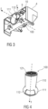
- Fig.4 shows the axial separator 100 in an external perspective view.
- Battery gas flows through the axial separator 100 along the axial direction z, which flows in from the battery housing 2 at an inlet-side end closed off by the sieve plate 121 and flows out at an outlet-side end closed off by the outlet trumpet 111.
- a cylindrical, hollow riser tube 110 is arranged, which has a Fig.4 not visible screw 120.
- a Fig.4 not visible screw 120.
- the particle ejection 112 is recessed in the axial separator 100.
- the particle ejection 112 extends as an elongated slot along the circumference of the axial separator 100 over a length of approximately one third to one sixth of the total circumference.
- the outer circumference of the outlet trumpet 111 is recessed and more curved than the remaining area of the outlet trumpet 111.
- the axial separator 100 is preferably made of a light, highly heat and pressure resistant material. Phenol-formaldehyde resins such as Bakelite ® PF 1110 are suitable for this purpose.
- Fig.5 shows the axial separator 100 in a dismantled state, that is: with the screw 120 removed.
- a locking groove 113 is recessed in the axial direction, which is designed to correspond to a locking lug 122 projecting in the radial direction y from the sieve plate 121.
- the screw axis 124 is firmly connected to the sieve plate 121 arranged vertically thereon.
- the locking lug 122 of the sieve plate 121 engages in the locking groove 113 of the riser pipe 110.
- the screw 120 and the riser pipe 110 with the particle ejector 112 are fixed against each other in a rotationally fixed manner in the assembled state.
- the screw axis 124 projects axially beyond the screw 120.
- Fig.6 shows the riser pipe 110 in a view from the inlet side, i.e. the end opposite the outlet trumpet 111.
- a helical pull 114 is arranged on the inner wall of the riser pipe 110.
- the helical pull 114 projects radially inward from the inner wall of the riser pipe 110.
- the winding of the pull 114 is the same in direction and pitch as the winding of the Screw flight 123 of the screw 120.
- the locked installation position that is: with the locking lug 122 of the sieve plate 121 engaged in the locking groove 113, the screw flight 123 and the pull 114 are directly opposite each other in the radial direction y.
- a circular segment-shaped tab 115 which projects radially inwards to the middle of the riser pipe 110 and tapers to a point.
- a worm bearing 116 which has a bore for receiving the end of the worm axle 124 which projects to the outlet side.
- the outer circular arc of the circular segment-shaped tab 115 is connected to the outlet-side end of the casing of the outlet trumpet 111 and extends on the casing of the outlet trumpet 111 over approximately the same angular range (or circumferential part) as the particle ejection 112. In other words: the particle ejection 112 and the tab 115 are aligned in the axial direction z.
- the outlet trumpet 111 is thus covered in the area of the tab 115, i.e. on the outlet side of the particle ejection 112.
- the worm bearing 116 arranged on the tab 115, together with the locking groove 113, ensures that the worm 120 is held in the riser pipe 110 in a rotationally fixed manner on both sides. Furthermore, the tab 115, since it offers resistance to the axial flow, causes a locally increased flow pressure of the outflowing battery gas in the area between the tab 115 and the particle ejection 112.
- Fig.7 shows an outlet-side plan view of the riser pipe 110 with attached outlet trumpet 111 and inserted screw 120.
- the functionality of the axial separator 100 is explained below.
- battery modules 3 can burst, releasing battery gas and hot particles, such as graphite or metal particles, which can form an ignitable mixture.
- the proposed axial separator 100 separates the particles from the escaping battery gas and thus reduces the likelihood of the mixture igniting.
- the sieve plate 121 prevents larger particles of the particle-battery gas mixture from entering the axial separator 100 and thus remains inside the Battery housing 2.
- the hole size of the sieve plate 121 is preferably selected so that particles with a diameter of 1.5 millimeters or larger are kept out.
- the helical guidance of the particle-battery gas mixture also causes turbulence on the inlet side of the sieve plate 121. As a result, separated large particles are guided away from the sieve plate 121 or blown away and clogging of the sieve plate 121 is avoided.
- the sieve plate 121 can also be convexly curved, which supports the removal or blowing away of the large particles deposited on it.
- the forced helical flow of the particle-battery gas mixture causes its separation, whereby under the influence of centrifugal force the heavier particles move radially outwards, i.e. towards the inner wall of the riser pipe 110, and thereby displace the lighter battery gas radially inwards, i.e. towards the screw axis 124.
- This radial separation increases in the axial direction z and achieves the greatest separation in the outlet trumpet 111 between particles that flow along the inner wall of the outlet trumpet 111 and the battery gas that is displaced into the interior of the outlet trumpet 111.
- the centrifugal force acting in the radial direction y simultaneously causes the radial exit of the particles through the slot-shaped particle ejection 112, as shown in Fig.7 shown schematically.
- the escape of the particles is supported by the flow pressure at the particle ejection 112, which is increased by means of the tab 115.
- the escaped particles are pressed through the particle channel 9 into the flow-calmed area of the separation chamber 10 and collected there.
- the battery gas mixture clarified in this way which only contains very small and light particles with diameters of typically between 10 micrometers and 100 micrometers, is expanded via the outlet trumpet 111, passes the downstream bursting disk 6 and/or the downstream bursting valve 7 and is released into the environment of the battery housing 2. Since the glow time of the particles decreases with their size, the remaining The very small and light particles contained in the battery burn up when they escape into the environment and can no longer ignite the battery gas.
- the time span between a thermal overload of a battery module 3, triggered for example by driving a metal nail into a battery pack 1, and a battery fire can be increased if the battery gas is led out of the battery housing 2 via the axial separator 100 according to the invention.
- ignition of the battery gas by particles was found within less than five minutes.
- ignition of the battery gas by particles was never found. Instead, the ignition of the battery gas always took place after more than 5 minutes due to other ignition sources such as HV flashovers.
- An advantage of the invention is therefore the improved application safety and the expanded application area of battery packs 1 which are provided with the proposed axial separator 100.
- Conventional particle-battery gas separators separate the particle-battery gas mixture by acceleration, whereby, due to their greater inertia, the heavier particles are discharged less quickly than the lighter battery gas.
- the particles sink to the ground somewhere along the acceleration path.
- An advantage of the invention in contrast, is that the particles are collected and stored in an encapsulated area, the separation chamber 10, which can easily be secured against the occurrence or spread of a fire.
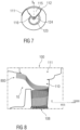
- Fig.8 illustrates the result of such a computer simulation with eight hundred particles schematically.
- the illustration shows a section of the axial separator 100.
- the axial separator 100 is "upside down", ie the outlet trumpet 111 is arranged at the top, below it is the riser pipe 110 and below that the inlet 8. To the left of this is the separation chamber 10.
- the path of the particles is shown in the form of a plurality of lines (trajectories 800), which schematically illustrate the total of eight hundred trajectories simulated in the Euler-Lagrange gas particle simulations.
- the illustration shows how the particles enter the axial separator 100 "from below” at a relatively low speed of less than 3,000 m/s, then are accelerated “upwards” to over 12,000 m/s as they flow through the helically wound gas channel in the z direction and finally exit the axial separator 100 in the y direction and enter the separation chamber 10, where they are abruptly slowed down and finally come to a standstill, ie: are deposited.
- the separation rate for particles with a diameter of 50 to 1000 ⁇ m is 100%.
- the installation position of the axial separator 100 in the motor vehicle it should be noted that this can be arbitrary, ie: the axial separator can in principle assume any spatial orientation in the motor vehicle.
- the resulting almost arbitrary installation position means an improvement in design freedom in the sense of flexible use of the limited installation space available in the motor vehicle.
Landscapes
- Chemical & Material Sciences (AREA)
- Engineering & Computer Science (AREA)
- Chemical Kinetics & Catalysis (AREA)
- Electrochemistry (AREA)
- General Chemical & Material Sciences (AREA)
- Materials Engineering (AREA)
- Manufacturing & Machinery (AREA)
- Sustainable Development (AREA)
- Life Sciences & Earth Sciences (AREA)
- Sustainable Energy (AREA)
- Power Engineering (AREA)
- Transportation (AREA)
- Mechanical Engineering (AREA)
- Aviation & Aerospace Engineering (AREA)
- Gas Exhaust Devices For Batteries (AREA)
- Secondary Cells (AREA)
- Battery Mounting, Suspending (AREA)
- Battery Electrode And Active Subsutance (AREA)
Description
- Die Erfindung betrifft einen Partikelabscheider für Batteriepacks gemäß dem Oberbegriff des Anspruchs 1. Ferner betrifft die Erfindung ein Batteriegehäuse mit einem solchen Partikelabscheider gemäß dem Oberbegriff des Anspruchs 6, ein Batteriepack gemäß dem Anspruch 7 umfassend ein solches Batteriegehäuse mit einem darin gekapselten Batteriemodul sowie ein Kraftfahrzeug gemäß dem Anspruch 9 umfassend ein solches Batteriepack.
- Das Dokument
DE 10 2013 204 585 A1 schlägt ein Batteriepack beispielsweise zur Verwendung in Elektro- oder Hybridkraftfahrzeugen vor. Für einen Entgasungsfall, bei dem eine einzelne Batteriezelle beispielsweise durch Überladung oder thermische Überlastung über einen Überdruckmechanismus Gas aus ihrem Inneren freisetzt, wird in einem Batteriepack-Gehäuse ein spezieller Freiraum vorgesehen, in den hinein sich das freigesetzte Gas entspannen kann und dabei seine Temperatur und seinen Druck reduzieren kann. Anschließend wird das Gas durch eine Überdruckablassvorrichtung aus dem Inneren des Batteriepack-Gehäuses nach außen freigesetzt. Das Gas durchströmt dabei einen in der Überdruckablassvorrichtung vorgesehenen Partikelabscheider beispielsweise in Form eines Zyklonabscheiders oder eines Oberflächenfilters mit einem Faserverbund oder einer offenporigen schwammartigen Struktur. In dem Gas enthaltene Partikel wie beispielsweise Graphitstaub können dabei beim Durchströmen des Partikelabscheiders herausgefiltert werden, um beispielsweise die Explosionsgefahr durch glühende Partikel innerhalb des austretenden Gases zu verringern. - Die
DE 10 2017 213 608 A1 beschreibt einen Gleichstromzyklonabscheider. Bei diesem wird eine Dispersion entlang eines Innengewindes geleitet, um dann in ihre Bestandteile aufgetrennt zu werden. - Zum weiteren Allgemeinen Stand der Technik kann ferner auf die
DE 02 57 918 A1 und dieDE 198 30 557 A1 verweisen werden, welche Filterelemente für aus einer Blei-Säure-Batterie austretende Gase zeigen. - Der Erfindung liegt die Aufgabe zu Grunde, einen verbesserten Partikelabscheider für Batteriepacks anzugeben. Der Erfindung liegt ferner die Aufgabe zu Grunde, ein verbessertes Batteriegehäuse für Batteriepacks, ein verbessertes Batteriepack sowie ein verbessertes Kraftfahrzeug anzugeben.
- Die Aufgabe wird hinsichtlich des Partikelabscheiders erfindungsgemäß durch einen Partikelabscheider mit den Merkmalen des Anspruchs 1 gelöst. Hinsichtlich des Batteriegehäuses, des Batteriepacks und des Kraftfahrzeugs wird die Aufgabe durch die Merkmale des Anspruchs 6, des Anspruchs 7 beziehungsweise des Anspruchs 9 gelöst.
- Vorteilhafte Ausgestaltungen der Erfindung sind Gegenstand der Unteransprüche.
- Ein Partikelabscheider ist zur Abscheidung von festen Partikeln aus einem Partikel-Batteriegas-Gemisch eingerichtet, und weist einen Einlass auf, der zur Einleitung des Partikel-Batteriegas-Gemischs mit Überdruck eingerichtet ist. Der Partikelabscheider weist einen Auslass auf, der zur Entspannung des Batteriegases eingerichtet ist.
- Erfindungsgemäß weist der Partikelabscheider einen Gaskanal auf, der entlang einer axialen Richtung schraubenförmig gewunden ist und der den Einlass mit dem Auslass fluidisch verbindet. Am auslassseitigen Ende weist der Partikelabscheider einen Partikelauswurf auf, der in einer radialen, das heißt: zur axialen Richtung senkrechten, Richtung geöffnet ist und zum Durchlass von Partikeln eingerichtet ist.
- Vorteilhaft wird durch die Abscheidung der Partikel von dem Batteriegas dessen Zündwahrscheinlichkeit verringert. Insbesondere wird verhindert, dass bei einer thermischen Überlastung einer Batteriezelle freigesetzte glühende Partikel, beispielsweise Graphit- oder Metallpartikel, das Batteriegas beim Austritt an die Umgebung entzünden.
- Herkömmliche Partikel-Batteriegas-Abscheider trennen das Partikel-Batteriegas-Gemisch durch Beschleunigung, wobei, aufgrund ihrer größeren Trägheit, die schwereren Partikel weniger schnell abgeleitet werden als das leichtere Batteriegas. Dabei sinken die Partikel irgendwo entlang der Beschleunigungsstrecke zu Boden.
- Demgegenüber weist der vorgeschlagene Partikelabscheider den Vorteil auf, dass die Partikel mit dem Batteriegas gemeinsam durch den schraubenförmigen Gaskanal geleitet werden und zusätzlich zu der axialen, in Längsrichtung des schraubenförmigen Gaskanals weisenden linearen Geschwindigkeitskomponente eine Winkelgeschwindigkeitskomponente, die tangential zur Schraubenform des Gaskanals gerichtet ist und die eine Zentrifugalkraft auf das bewegte Partikel-Batteriegasgemisch bewirkt. Unter dem Einfluss der Zentrifugalkraft werden die schwereren Partikel radial nach außen, also: senkrecht zur linearen Geschwindigkeitskomponente und senkrecht zur Winkelgeschwindigkeitskomponente, bewegt und verdrängen dabei das leichtere Batteriegas radial nach innen.
- Durch die radiale Öffnung des Partikelauswurfs treten die Partikel an dieser Stelle aus und können zentral gesammelt und aufgenommen werden, während das Batteriegas im Wesentlichen ungebremst in axialer Richtung ausströmen und entspannen kann. In vorteilhafter Weise ist der Strömungswiderstand des vorgeschlagenen Partikelabscheiders gegenüber den Lösungen aus dem Stand der Technik vermindert. Dadurch ist ein besonders effizienter Druckabbau eines unter Überdruck durch den Partikelabscheider ausgelassenen Partikel-Batteriegasgemischs möglich.
- Erfindungsgemäß ist der Gaskanal durch eine in einem Steigrohr angeordnete Schnecke gebildet. Die Schnecke weist eine Schneckenwendel auf, die um eine axiale, das heißt: in Längsrichtung des Steigrohrs erstreckte, Schneckenachse gewunden ist.
- Das Steigrohr weist einen radial nach innen zur Schneckenachse zu vorspringenden, in axialer Längsrichtung gewundenen Zug auf. Der Zug ist korrespondierend zur Schneckenwendel gewunden.
- Das Steigrohr ist einlassseitig mit einer Siebplatte gasdurchlässig verschlossen und auslassseitig in einer Auslasstrompete trichterförmig geweitet. Der Partikelauswurf ist als radialer Schlitz im Mantel des Steigrohrs im Bereich der Auslasstrompete angeordnet.
- Mittels der Schneckenwendel und dem korrespondierend gewundenen Zug kann in sehr einfacher Weise ein schraubenförmiger Gaskanal gebildet werden. Schnecke und Steigrohr können voneinander demontierbar ausgebildet sein. Dadurch sind eine einfache und kostengünstige Herstellung und Montage möglich. Zudem bietet die Ausführung des schraubenförmigen Gaskanals mittels einer Schnecke den Vorteil, dass ein besonders großer lichter Innendurchmesser des Steigrohres für die Durchleitung des Partikel-Batteriegasgemischs verfügbar ist, so dass ein besonders guter Druckabbau über den Partikelabscheider ermöglicht ist.
- In einer Ausführungsform weisen die Schneckenwendel und der Zug an der Innenseite des Steigrohrmantels jeweils näherungsweise drei Windungen auf. Eine Vergrößerung der Windungsanzahl der Schneckenwendel bewirkt eine Vergrößerung der Radialbeschleunigung, und somit auch eine verbesserte Trennung der Partikel von dem Batteriegas, wobei jedoch der Grad der Verbesserung durch eine zusätzliche Windung mit länger werdender Schneckenwendel allmählich abnimmt. Eine Anzahl von näherungsweise drei Windungen hat sich als optimaler Kompromiss zwischen einer guten Trennwirkung des Partikelabscheiders und den primär durch dessen axiale Länge bedingten Anforderungen an den Bauraum herausgestellt.
- Bei einer Ausführungsform ist der Partikelauswurf über eine volle Wendelhöhe der Schneckenwendel erstreckt und radial geöffnet. Dadurch lässt sich ein möglichst vollständiges Ausschleudern der radial nach außen gedrängten Partikel und somit eine besonders gute Trennwirkung des Partikelabscheiders erzielen.
- Bei einer Ausführungsform ist die Siebplatte für das Zurückhalten von Partikeln mit einem Querschnitt von mindestens 1,5 Millimeter eingerichtet. Das Zurückhalten von größeren, somit auch schwereren und trägeren Partikeln, erlaubt eine kürzere Bauform des Partikelabscheiders und einen verbesserten Durchlass des Partikel-Batteriegasgemischs. Zugleich erlauben ausreichend große Sieböffnungen einen geringen Strömungswiderstand und damit einen effizienten Überdruckabbau durch den Partikelabscheider. Sieböffnungen mit einem Querschnitt von etwa 1,5 Millimeter haben sich als guter Kompromiss zwischen einer guten Trennwirkung und einem geringen Strömungswiderstand herausgestellt.
- Ein Batteriegehäuse ist zur gasdichten Kapselung mindestens eines Batteriemoduls eingerichtet und umfasst eine Isoliereinlage mit mindestens einem darin angeordneten Durchbruch, der zur fluidischen Verbindung des Innenraums des Batteriegehäuses (2) mit dessen Umgebung oberhalb eines vorbestimmten Überdruckgrenzwertes im Innenraum eingerichtet ist.
- In dem mindestens einen Durchbruch ist ein erfindungsgemäßer Partikelabscheider angeordnet. In der Isoliereinlage ist mindestens eine Abscheidekammer ausgespart, die fluidisch mit dem Partikelauswurf des mindestens einen Partikelabscheiders verbunden ist.
- Nach einer thermischen Überlastung einer Batteriezelle des mindestens einen Batteriemoduls wird gebildetes Partikel-Batteriegas-Gemisch, wenn der vorbestimmte Überdruckgrenzwert überschritten ist, durch den Partikelabscheider ausgeleitet. Dabei werden möglicherweise noch glühende Partikel, die in die Umgebung austretendes Batteriegas entzünden könnten, durch den Partikelauswurf in die strömungsberuhigte Abscheidekammer geleitet. Somit wird die Wahrscheinlichkeit für eine Entzündung des austretenden Batteriegases signifikant verringert.
- Ein Batteriepack umfasst ein erfindungsgemäßes Batteriegehäuse mit dem erfindungsgemäßen Partikelabscheider, wobei in dem Batteriegehäuse mindestens ein Batteriemodul gekapselt ist. Durch die Hemmung der Entzündung von im thermischen Überlastfall austretendem Batteriegas kann die Betriebssicherheit derartiger Batteriepacks verbessert werden.
- In einer Ausführungsform umfasst das mindestens eine Batteriemodul mindestens eine Lithium-lonen-Batteriezelle. Lithium-lonen-Batteriezellen weisen eine hohe Energiedichte und eine lange Lebensdauer auf und emittieren im thermischen Überlastfall ein Partikel-Batteriegas-Gemisch, dessen Entzündungswahrscheinlichkeit mit dem erfindungsgemäßen Partikelabscheider wirksam reduziert werden kann.
- Ferner wird ein Kraftfahrzeug, vorzugsweise ein Elektrofahrzeug, vorgeschlagen, das mindestens teilweise mit einem solchen Batteriepack betrieben und/oder gespeist wird. Ein solches Kraftfahrzeug weist eine besonders hohe Betriebssicherheit auf. Insbesondere genügt ein derart ausgebildetes Elektrofahrzeug geltenden gesetzlichen, regulatorischen und/oder normativen Sicherheitsvorschriften hinsichtlich der Zeitspanne zwischen dem Feststellen einer thermischen Überlastung und dem Einsetzen eines Batteriebrandes.
- Ausführungsbeispiele der Erfindung werden im Folgenden anhand von Zeichnungen näher erläutert.
- Dabei zeigen:
- Fig. 1
- schematisch einen Querschnitt durch ein Batteriepack,
- Fig. 2
- schematisch eine einlassseitige perspektivische Ansicht auf eine Isoliereinlage,
- Fig. 3
- schematisch eine auslassseitige perspektivische Ansicht auf eine Isoliereinlage,
- Fig. 4
- schematisch eine perspektivische Ansicht auf einen Axialabscheider,
- Fig. 5
- schematisch eine perspektivische Ansicht auf einen demontierten Axialabscheider mit Steigrohr und Schnecke,
- Fig. 6
- schematisch eine perspektivische Detailansicht auf ein Steigrohr,
- Fig. 7
- schematisch eine auslassseitige Ansicht auf einen Axialabscheider und
- Fig. 8
- Ergebnis einer Computer-Simulation mit achthundert Partikel, wobei der Axialabscheider "auf dem Kopf" steht.
- Einander entsprechende Teile sind in allen Figuren mit den gleichen Bezugszeichen versehen.
-
Fig. 1 zeigt einen schematischen Querschnitt durch ein Batteriepack 1 mit einem Batteriegehäuse 2. Das Batteriegehäuse 2 ist gasdicht ausgebildet. Im Inneren des Batteriegehäuses 2 sind Batteriemodule 3 angeordnet. - Bei einer Beschädigung des Batteriepacks 1 oder eines Batteriemoduls 3 ist es möglich, dass Batteriegase gebildet werden, die zur Vermeidung einer Explosion des Batteriepacks 1 kontrolliert an die Umgebung abgeführt werden müssen. Die Ausleitung von Batteriegasen aus dem Batteriegehäuse 2 erfolgt entlang von Isoliereinlagen 4.
- Die Isoliereinlagen 4 weisen nachfolgend noch näher erläuterte, für die Batteriegasausleitung eingerichtete Durchbrüche 5 zwischen dem Inneren des Batteriegehäuses 2 und dessen Umgebung auf, die durch jeweils eine Berstscheibe 6 und/oder ein Berstventil 7 gasdicht abgeschlossen sind. Erreicht ein Überdruck im Inneren des Batteriegehäuses 2 einen vorbestimmten Grenzwert, so birst die Berstscheibe 6 und/oder öffnet das Berstventil 7. Damit ist die Entspannung des unter Überdruck stehenden Batteriegases durch die Isoliereinlage 4 hindurch möglich.
-
Fig. 2 zeigt schematisch eine perspektivische Ansicht auf eine Isoliereinlage 4 aus Sicht des Gehäuseinneren des Batteriegehäuses 2. Bei geborstener Berstscheibe 6 oder geöffnetem Berstventil 7 werden Batteriegase durch einen Axialabscheider 100 von einem Einlass 8 entlang einer axialen Richtung z in die äußere Umgebung des Batteriegehäuses 2 abgeleitet. Der Axialabscheider 100 ist in dem zylindrischen Durchbruch 5 durch die Isoliereinlage 4 angeordnet. Einlassseitig ist der Axialabscheider 100 über eine Siebplatte 121 abgeschlossen. Die Anordnung und Funktionsweise der Siebplatte 121 wird nachfolgend noch näher erläutert. -
Fig. 3 zeigt schematisch eine perspektivische Ansicht auf die Isoliereinlage 4 aus der gegenüberliegenden Sicht, das heißt: von der Umgebung des Batteriegehäuses 2 aus. Auslassseitig weist der Axialabscheider 100 eine trompetenartig geweitete Auslasstrompete 111 auf, über die austretendes Batteriegas an die Umgebung abgegeben wird. - In der Auslasstrompete 111 ist ein radialer, schlitzförmiger Partikelauswurf 112 ausgespart. Der Partikelauswurf 112 ist für den Auswurf fester Partikel vorgesehen, die vom austretenden Batteriegas mitgeführt werden und klein genug sind, um die einlassseitige Siebplatte 121 zu passieren.
- Die Partikel werden, wie nachfolgend noch genauer erläutert, in einer radialen Richtung y durch den Partikelauswurf 112 geleitet, während das Batteriegas in axialer Richtung z ausströmt. Die ausgeworfenen Partikel werden über einen Partikelkanal 9, der als fluidische Verbindung zwischen dem Partikelauswurf 112 und einer Abscheidekammer 10 ausgebildet ist, in die Abscheidekammer 10 geleitet, die in der Isoliereinlage 4 ausgespart ist.
-
Fig. 4 zeigt den Axialabscheider 100 in einer äußeren perspektivischen Ansicht. Der Axialabscheider 100 wird entlang der axialen Richtung z von Batteriegas durchströmt, das an einem einlassseitigen, mit der Siebplatte 121 abgeschlossenen Ende vom Batteriegehäuse 2 einströmt und an einem auslassseitigen, mit der Auslasstrompete 111 abgeschlossenen Ende ausströmt. - Zwischen der Siebplatte 121 und der Auslasstrompete 111 ist ein zylindrisches, hohles Steigrohr 110 angeordnet, das im Inneren eine in
Fig. 4 nicht sichtbare Schnecke 120 aufnimmt. Am Ansatz der Auslasstrompete 111 an dem Steigrohr 110 ist im Mantel des Axialabscheiders 100 der Partikelauswurf 112 ausgespart. Der Partikelauswurf 112 erstreckt sich als länglicher Schlitz entlang des Umfangs des Axialabscheiders 100 über eine Länge von etwa einem Drittel bis einem Sechstel des Gesamtumfangs. - Über die Länge des Partikelauswurfs 112 ist der äußere Umfang der Auslasstrompete 111 zurückgenommen und stärker gewölbt als der übrige Bereich der Auslasstrompete 111.
- Der Axialabscheider 100 ist vorzugsweise aus einem leichten, hoch wärme- und druckbeständigen Material gefertigt. Hier kommen u.a. Phenol-Formaldehyd-Harze wie z.B. Bakelite® PF 1110 in Frage.
-
Fig. 5 zeigt den Axialabscheider 100 in demontiertem Zustand, das heißt: mit entnommener Schnecke 120. Am einlassseitigen Ende des Steigrohres 110 ist in axialer Richtung eine Arretiernut 113 ausgespart, die korrespondierend zu einer in radialer Richtung y von der Siebplatte 121 vorspringenden Arretiernase 122 ausgebildet ist. - Die entnommene Schnecke 120 umfasst eine Schneckenwendel 123 mit einer in Längsrichtung der Schnecke 120, das heißt: in axialer Richtung z, erstreckten Schneckenachse 124. Vorliegend weist die Schneckenwendel 123 etwa 2,5 volle Windungen auf. Es ist aber auch möglich, dass die Schneckenwendel 123 eine andere Windungszahl aufweist. Vorzugsweise weist die Schneckenwendel 123 näherungsweise drei Windungen bei einer axialen Ausdehnung von etwa 100 bis 120 mm auf.
- Am einlassseitigen Ende ist die Schneckenachse 124 fest mit der senkrecht darauf angeordneten Siebplatte 121 verbunden. In montiertem Zustand rastet die Arretiernase 122 der Siebplatte 121 in der Arretiernut 113 des Steigrohres 110 ein. Dadurch sind die Schnecke 120 und das Steigrohr 110 mit dem Partikelauswurf 112 in montiertem Zustand drehfest gegeneinander fixiert.
- Am auslassseitigen Ende springt die Schneckenachse 124 axial über die Schnecke 120 hinaus vor.
-
Fig. 6 zeigt das Steigrohr 110 in einer Ansicht vom einlassseitigen, das heißt: der Auslasstrompete 111 gegenüberliegenden Ende her. Auf der Innenwand des Steigrohrs 110 ist ein schraubenförmiger Zug 114 angeordnet. Der schraubenförmige Zug 114 springt radial nach innen gerichtet von der Innenwand des Steigrohrs 110 vor. Die Windung des Zugs 114 ist in Richtung und Steigung gleich der Windung der Schneckenwendel 123 der Schnecke 120 ausgebildet. In der arretierten Einbauposition, das heißt: mit in der Arretiernut 113 eingerasteten Arretiernase 122 der Siebplatte 121, liegen sich die Schneckenwendel 123 und der Zug 114 in radialer Richtung y direkt gegenüber. - Am auslassseitigen Ende der Auslasstrompete 111 ist eine kreissegmentförmige Lasche 115 angeordnet, die radial nach innen bis zur Mitte des Steigrohrs 110 vorspringt und spitz zuläuft. Am spitz zulaufenden inneren Ende der Lasche 115 ist ein Schneckenlager 116 angeordnet, das eine Bohrung zur Aufnahme des auslassseitig vorragenden Endes der Schneckenachse 124 aufweist.
- Der äußere Kreisbogen der kreissegmentförmigen Lasche 115 ist mit dem auslassseitigen Ende des Mantels der Austrittstrompete 111 verbunden und erstreckt sich am Mantel der Austrittstrompete 111 näherungsweise über den gleichen Winkelbereich (oder Umfangsteil) wie der Partikelauswurf 112. Mit anderen Worten: der Partikelauswurf 112 und die Lasche 115 sind in axialer Richtung z fluchtend angeordnet. Die Austrittstrompete 111 ist somit im Bereich der Lasche 115, das heißt: auslassseitig des Partikelauswurfs 112, abgedeckt.
- Das an der Lasche 115 angeordnete Schneckenlager 116 bewirkt zusammen mit der Arretiernut 113 die beidseitige, drehfeste Aufnahme der Schnecke 120 im Steigrohr 110. Ferner bewirkt die Lasche 115, da sie der axialen Strömung einen Widerstand entgegensetzt, einen in dem Bereich zwischen der Lasche 115 und dem Partikelauswurf 112 lokal erhöhten Strömungsdruck des ausströmenden Batteriegases.
-
Fig. 7 zeigt eine auslassseitige Draufsicht auf das Steigrohr 110 mit angesetzter Auslasstrompete 111 und eingesetzter Schnecke 120. - Nachfolgend wird die Funktionsweise des Axialabscheiders 100 erläutert. Bei einer thermischen Überlastung können Batteriemodule 3 bersten und dabei Batteriegas und heiße Partikel, beispielsweise Graphit- oder Metallpartikel freisetzen, die ein zündfähiges Gemisch bilden können. Der vorgeschlagene Axialabscheider 100 trennt die Partikel vom ausströmenden Batteriegas und verringert so die Wahrscheinlichkeit für eine Zündung des Gemisches.
- Durch die Siebplatte 121 werden größere Partikel des Partikel-Batteriegas-Gemischs vom Eintritt in den Axialabscheider 100 abgehalten und verbleiben somit im Inneren des Batteriegehäuses 2. Die Lochgröße der Siebplatte 121 wird vorzugsweise so gewählt, dass Partikel mit einem Durchmesser von 1,5 Millimeter oder größer abgehalten werden.
- Batteriegas und Partikel, deren Durchmesser kleiner als die Lochgröße der Siebplatte 121 ist, treten in den Axialabscheider 100 ein und werden durch die Schneckenwendel 123 und den am Rand des Steigrohrs 110 gegenüberliegenden, korrespondierend ausgebildeten Zug 114 auf einer schraubenförmigen Bahn in axialer Richtung z durch den Axialabscheider 100 geleitet.
- Die schraubenförmige Führung des Partikel-Batteriegas-Gemischs bewirkt Verwirbelungen auch auf der Einlassseite der Siebplatte 121. Dadurch werden abgeschiedene große Partikel von der Siebplatte 121 weggeführt oder verweht und ein Verstopfen der Siebplatte 121 vermieden.
- Die Siebplatte 121 kann zudem konvex gewölbt ausgebildet sein, was das Wegführen oder Verwehen der darauf abgeschiedenen, großen Partikel unterstützt.
- Ferner bewirkt die erzwungene schraubenförmige Strömung des Partikel-Batteriegas-Gemischs dessen Entmischung, wobei sich unter dem Einfluss der Zentrifugalkraft die schwereren Partikel radial nach außen, also: auf die Innenwand des Steigrohrs 110 zu, bewegen und dabei das leichtere Batteriegas radial nach innen, also: auf die Schneckenachse 124 zu verdrängen. Diese radiale Entmischung nimmt in axialer Richtung z zu und erreicht in der Auslasstrompete 111 die größte Trennung zwischen Partikeln, die an der Innenwand der Auslasstrompete 111 strömen, und dem Batteriegas, das ins Innere der Auslasstrompete 111 verdrängt wird.
- Die in radiale Richtung y wirkende Zentrifugalkraft bewirkt zugleich das radiale Austreten der Partikel durch den schlitzförmigen Partikelauswurf 112, wie in
Fig. 7 schematisch dargestellt. Das Austreten der Partikel wird durch den mittels der Lasche 115 erhöhten Strömungsdruck am Partikelauswurf 112 unterstützt. - Die ausgetretenen Partikel werden durch den Partikelkanal 9 in den strömungsberuhigten Bereich der Abscheidekammer 10 gedrückt und dort gesammelt. Das auf diese Weise geklärte, nur noch sehr kleine und leichte Partikel mit Durchmessern von typischerweise zwischen 10 Mikrometer und 100 Mikrometer enthaltende Batteriegasgemisch wird über die Auslasstrompete 111 entspannt, passiert die nachgeordnete Berstscheibe 6 und/oder das nachgeordnete Berstventil 7 und wird an die Umgebung des Batteriegehäuses 2 abgegeben. Da die Glühzeit der Partikel mit deren Größe abnimmt, sind die noch enthaltenen sehr kleinen und leichten Partikel beim Austritt in die Umgebung verglüht und können das Batteriegas nicht mehr entzünden.
- Es hat sich herausgestellt, dass die Zeitspanne zwischen einer thermischen Überlastung eines Batteriemoduls 3, ausgelöst beispielsweise durch Eintreiben eines metallischen Nagels in ein Batteriepack 1, und einem Batteriebrand erhöht werden kann, wenn das Batteriegas über den erfindungsgemäßen Axialabscheider 100 aus dem Batteriegehäuse 2 geführt wird. So wurde beispielsweise bei Vortests ohne den erfindungsgemäßen Partikelabscheider eine Entzündung des Batteriegases durch Partikel innerhalb von weniger als fünf Minuten festgestellt. Bei Tests mit dem erfindungsgemäßen Partikelabscheider wurde dagegen niemals eine Entzündung des Batteriegases durch Partikel festgestellt. Stattdessen fand die Entzündung des Batteriegases immer nach mehr als 5 Minuten durch andere Zündquellen wie z.B. HV-Überschläge statt. Damit steht für die Warnung eines Nutzers, beispielsweise eines Fahrzeuginsassen eines Elektrofahrzeugs, das mit derartigen Batteriepacks 1 gespeist wird, eine vergrößerte Zeitspanne zur Verfügung, welche den gesetzlichen Vorschriften und Normen entspricht. Ein Vorteil der Erfindung besteht somit in der verbesserten Anwendungssicherheit und dem erweiterten Einsatzbereich von Batteriepacks 1, die mit dem vorgeschlagenen Axialabscheider 100 versehen sind.
- Herkömmliche Partikel-Batteriegas-Abscheider trennen das Partikel-Batteriegas-Gemisch durch Beschleunigung, wobei, aufgrund ihrer größeren Trägheit, die schwereren Partikel weniger schnell abgeleitet werden als das leichtere Batteriegas. Dabei sinken die Partikel irgendwo entlang der Beschleunigungsstrecke zu Boden. Ein Vorteil der Erfindung besteht demgegenüber darin, dass die Partikel in einem gekapselten Bereich, der Abscheidekammer 10, gesammelt und endgelagert werden, welcher leicht gegen die Entstehung oder Ausbreitung eines Brandes gesichert werden kann.
- Um die Wirksamkeit des Axialabscheiders 100 zu testen, wurden Computer-Simulationen durchgeführt. Hierfür wurde die Software StarCCM+ eingesetzt und 3D Euler-Lagrange Gas-Partikel-Simulationen durchgeführt.
- Folgende Rahmenbedingungen wurden bei der Computer-Simulation angenommen: Stationäre Simulation, Gasmassenflussrate 25 g/s, Gaseintrittstemperatur 300 °C (Worst-Case-Szenario), Wandtemperatur adiabatisch, Partikelanfangstemperatur 1000 °C, Partikelmaterial Graphit und NMC (Lithium-Nickel-Mangan-Kobalt-Oxid) und Kupfer, Partikelform sphärisch.
- Folgende Ergebnisse wurden bei der Computer-Simulation erhalten: Druckabfall im Axialabscheider 100 340 mbar, maximale Machzahl 0.54, Abscheiderate für Partikel mit einem Durchmesser von 50 bis 1000 µm 100 %.
-
Fig. 8 illustriert das Ergebnis einer solchen Computer-Simulation mit achthundert Partikeln schematisch. In der Darstellung ist der Axialabscheider 100 ausschnittsweise gezeigt. Der Axialabscheider 100 steht dabei "auf dem Kopf", d.h. die Auslasstrompete 111 ist oben angeordnet, darunter befindet sich das Steigrohr 110 und darunter der Einlass 8. Links daneben befindet sich die Abscheidekammer 10. Der Weg der Partikel ist in Form einer Mehrzahl von Linien (Trajektorien 800) dargestellt, welche schematisch die insgesamt achthundert in der Euler-Lagrange Gas-Partikel-Simulationen simulierten Trajektorien verdeutlichen. Der Darstellung ist zu entnehmen, wie die Partikel mit relativ geringer Geschwindigkeit von unter 3.000 m/s "von unten" in den Axialabscheider 100 eintreten, dann beim Durchströmen des schraubenförmig gewundenen Gaskanals in z-Richtung "nach oben" auf über 12.000 m/s beschleunigt werden und schließlich in y-Richtung aus dem Axialabscheider 100 aus- und in die Abscheidekammer 10 eintreten, wo sie abrupt abgebremst werden und letztendlich zum Stillstand kommen, d.h.: abgelagert werden. Wie oben bereits erwähnt, beträgt die Abscheiderate für Partikel mit einem Durchmesser von 50 bis 1000 µm 100 %. - Bezüglich der Einbaulage des Axialabscheiders 100 im Kraftfahrzeug ist anzumerken, dass diese beliebig sein kann, d.h.: der Axialabscheider kann prinzipiell jede räumliche Orientierung im Kraftfahrzeug einnehmen. Dabei gilt jedoch die Einschränkung, dass bei der Einbaulage sichergestellt sein muss, dass die in der Abscheidekammer 10 abgelagerten Partikel nicht wieder durch den schlitzförmigen Partikelauswurf 112 zurück in den Axialabscheider fallen. Die dadurch nahezu beliebige Einbaulage bedeutet eine Verbesserung der Designfreiheit im Sinne einer flexiblen Ausnutzung des im Kraftfahrzeug zur Verfügung stehenden, knappen Bauraums.
-
- 1
- Batteriepack
- 2
- Batteriegehäuse
- 3
- Batteriemodul
- 4
- Isoliereinlage
- 5
- Durchbruch
- 6
- Berstscheibe
- 7
- Berstventil
- 8
- Einlass
- 9
- Partikelkanal
- 10
- Abscheidekammer
- 100
- Axialabscheider, Partikelabscheider
- 110
- Steigrohr
- 111
- Auslasstrompete, Auslass
- 112
- Partikelauswurf
- 113
- Arretiernut
- 114
- Zug
- 115
- Lasche
- 116
- Schneckenlager
- 120
- Schnecke
- 121
- Siebplatte
- 122
- Arretiernase
- 123
- Schneckenwendel
- 124
- Schneckenachse
- z
- axiale Richtung
- y
- radiale Richtung
Claims (9)
- Partikelabscheider (100), der zur Abscheidung von festen Partikeln aus einem an einem Einlass (8) mit Überdruck eingeleiteten Partikel-Batteriegas-Gemisch und zur Entspannung des Batteriegases an einem Auslass (111) eingerichtet ist,dadurch gekennzeichnet, dass der Partikelabscheider (100) einen schraubenförmig entlang einer axialen Richtung (z) gewundenen Gaskanal aufweist, der den Einlass (8) mit dem Auslass (111) fluidisch verbindet, wobei der Gaskanal am auslassseitigen Ende einen Partikelauswurf (112) aufweist, der in einer radialen Richtung (y) geöffnet und zum Durchlass von Partikeln eingerichtet ist,dadurch gekennzeichnet, dassder Gaskanal durch eine in einem Steigrohr (110) angeordnete Schnecke (120) mit einer um eine axiale Schneckenachse (124) gewundene Schneckenwendel (123) gebildet ist, wobei das Steigrohr (110) einen radial nach innen vorspringenden, korrespondierend zur Schneckenwendel (123) gewundenen Zug (114) aufweist, wobei das Steigrohr (110) einlassseitig mit einer Siebplatte (121) gasdurchlässig verschlossen ist und auslassseitig in einer Auslasstrompete (111) trichterförmig geweitet ist und wobei der Partikelauswurf (112) als radialer Schlitz im Mantel des Steigrohrs (110) im Bereich der Auslasstrompete (111) angeordnet ist.
- Partikelabscheider (100) nach Anspruch 1,
dadurch gekennzeichnet, dass die Schneckenwendel (123) und der Zug (114) jeweils drei Windungen aufweisen. - Partikelabscheider (100) nach Anspruch 1 oder 2,
dadurch gekennzeichnet, dass der Partikelauswurf (112) über eine volle Wendelhöhe der Schneckenwendel (123) erstreckt ausgebildet und radial geöffnet ist. - Partikelabscheider (100) nach einem der Ansprüche 1 bis 3,
dadurch gekennzeichnet, dass die Siebplatte (121) für das Zurückhalten von Partikeln mit einem Querschnitt von mindestens 1,5 Millimetern eingerichtet ist. - Partikelabscheider (100) nach einem der Ansprüche 1 bis 4,
dadurch gekennzeichnet, dass die Siebplatte (121) konvex gewölbt ausgebildet ist. - Batteriegehäuse (2), das zur gasdichten Kapselung mindestens eines Batteriemoduls (3) eingerichtet ist, umfassend eine Isoliereinlage (4) mit mindestens einem darin angeordneten Durchbruch (5), der zur fluidischen Verbindung des Innenraums des Batteriegehäuses (2) mit dessen Umgebung oberhalb eines vorbestimmten Überdruckgrenzwertes im Innenraum eingerichtet ist,
dadurch gekennzeichnet, dass in dem mindestens einen Durchbruch (5) ein Partikelabscheider (100) nach einem der vorhergehenden Ansprüche angeordnet ist und in der Isoliereinlage (4) mindestens eine Abscheidekammer (10) ausgespart ist, die fluidisch mit dem Partikelauswurf (112) des mindestens einen Partikelabscheiders (100) verbunden ist. - Batteriepack (1) umfassend ein Batteriegehäuse (2) nach Anspruch 6 mit mindestens einem in dem Batteriegehäuse (2) gekapselten Batteriemodul (3).
- Batteriepack (1) nach Anspruch 7,
dadurch gekennzeichnet, dass das mindestens eine Batteriemodul (3) mindestens eine Lithium-lonen-Batteriezelle umfasst. - Kraftfahrzeug mit einem Batteriepack (1) nach Anspruch 7 oder 8, das zur Speisung und/oder zum Betrieb des Kraftfahrzeugs eingerichtet ist.
Applications Claiming Priority (2)
| Application Number | Priority Date | Filing Date | Title |
|---|---|---|---|
| DE102019008657.0A DE102019008657A1 (de) | 2019-12-13 | 2019-12-13 | Partikelabscheider für Batteriepacks und Batteriepack mit Partikelabscheider |
| PCT/EP2020/084549 WO2021115936A1 (de) | 2019-12-13 | 2020-12-03 | Partikelabscheider für batteriepacks und batteriepack mit partikelabscheider |
Publications (3)
| Publication Number | Publication Date |
|---|---|
| EP4073878A1 EP4073878A1 (de) | 2022-10-19 |
| EP4073878C0 EP4073878C0 (de) | 2024-09-04 |
| EP4073878B1 true EP4073878B1 (de) | 2024-09-04 |
Family
ID=73740386
Family Applications (1)
| Application Number | Title | Priority Date | Filing Date |
|---|---|---|---|
| EP20820370.3A Active EP4073878B1 (de) | 2019-12-13 | 2020-12-03 | Partikelabscheider für batteriepacks und batteriepack mit partikelabscheider |
Country Status (7)
| Country | Link |
|---|---|
| US (1) | US12555868B2 (de) |
| EP (1) | EP4073878B1 (de) |
| JP (1) | JP7318133B2 (de) |
| KR (1) | KR20220100926A (de) |
| CN (1) | CN114788083B (de) |
| DE (1) | DE102019008657A1 (de) |
| WO (1) | WO2021115936A1 (de) |
Families Citing this family (2)
| Publication number | Priority date | Publication date | Assignee | Title |
|---|---|---|---|---|
| CN116349063A (zh) * | 2020-11-13 | 2023-06-27 | 江苏时代新能源科技有限公司 | 箱体、电池、用电设备及电池的制造方法 |
| DE102024002572A1 (de) | 2023-08-11 | 2025-02-13 | Mercedes-Benz Group AG | Ein System zum Ablassen von Partikeln aus einem Batteriegehäuse |
Family Cites Families (17)
| Publication number | Priority date | Publication date | Assignee | Title |
|---|---|---|---|---|
| SE440978B (sv) * | 1983-08-25 | 1985-09-02 | Tetra Pak Int | Anordning for separering av partiklar fran gas, speciellt vid tillverkning av aseptiska forpackningsbehallare |
| AUPN474095A0 (en) * | 1995-08-09 | 1995-08-31 | Barnes, Peter Haddon | Improved dust separator for process flue gas |
| GB2327141B (en) * | 1997-07-10 | 2001-07-25 | Ind Accumulatori Spa Soc | A lead-acid accumulator, particularly for motor vehicles |
| DE10257918C5 (de) | 2001-12-17 | 2013-12-19 | Akkumulatorenfabrik Moll Gmbh & Co. Kg | Akkumulator |
| ATE427169T1 (de) * | 2003-03-10 | 2009-04-15 | Aco Co Ltd | Verfahren und vorrichtung zur trennung |
| SE532661C2 (sv) * | 2007-03-12 | 2010-03-16 | Centriclean Systems Ab | Anordning för avskiljning av partiklar |
| US8012226B2 (en) * | 2007-07-17 | 2011-09-06 | Ging-Chung Chen | Air separator and purifier device |
| JP2011171039A (ja) * | 2010-02-17 | 2011-09-01 | Panasonic Corp | 鉛蓄電池用の排気栓および鉛蓄電池 |
| DE102013204585A1 (de) * | 2013-03-15 | 2014-09-18 | Robert Bosch Gmbh | Batteriepack mit Überdruckablassvorrichtung und Partikelabscheider |
| US10105736B2 (en) | 2014-01-31 | 2018-10-23 | Thyssenkrupp Industrial Solutions Ag | Separator with a bypass |
| US9865852B2 (en) | 2015-06-25 | 2018-01-09 | Tesla, Inc. | Energy storage container with vortex separator |
| JP6821391B2 (ja) * | 2016-10-26 | 2021-01-27 | 三洋電機株式会社 | 電源装置及びこれを用いる車両並びに蓄電装置 |
| DE102017213608B4 (de) | 2017-08-04 | 2020-06-18 | Tayyar Bayrakci | Gleichstromzyklonabscheider |
| CN114391003A (zh) * | 2019-08-14 | 2022-04-22 | 申克普若赛斯欧洲有限公司 | 用于分离散状产品的气动输送系统 |
| US20210359374A1 (en) * | 2020-05-12 | 2021-11-18 | Samsung Sdi Co., Ltd. | Battery system and vehicle including the battery system |
| DE102021102908A1 (de) * | 2021-02-09 | 2022-08-11 | Audi Aktiengesellschaft | Entgasungseinrichtung, Batterie und Kraftfahrzeug |
| DE102022102826B4 (de) * | 2022-02-07 | 2025-09-11 | Audi Aktiengesellschaft | Batteriegehäuse für einen Energiespeicher, Energiespeicher für ein Kraftfahrzeug und Verfahren zum Abführen eines Gas-Partikel-Gemischs aus einem Batteriegehäuse |
-
2019
- 2019-12-13 DE DE102019008657.0A patent/DE102019008657A1/de active Pending
-
2020
- 2020-12-03 US US17/783,213 patent/US12555868B2/en active Active
- 2020-12-03 KR KR1020227019840A patent/KR20220100926A/ko not_active Ceased
- 2020-12-03 JP JP2022534161A patent/JP7318133B2/ja active Active
- 2020-12-03 CN CN202080085509.4A patent/CN114788083B/zh active Active
- 2020-12-03 WO PCT/EP2020/084549 patent/WO2021115936A1/de not_active Ceased
- 2020-12-03 EP EP20820370.3A patent/EP4073878B1/de active Active
Also Published As
| Publication number | Publication date |
|---|---|
| EP4073878C0 (de) | 2024-09-04 |
| WO2021115936A1 (de) | 2021-06-17 |
| CN114788083B (zh) | 2025-02-28 |
| JP2023506412A (ja) | 2023-02-16 |
| KR20220100926A (ko) | 2022-07-18 |
| US12555868B2 (en) | 2026-02-17 |
| US20230019147A1 (en) | 2023-01-19 |
| JP7318133B2 (ja) | 2023-07-31 |
| CN114788083A (zh) | 2022-07-22 |
| DE102019008657A1 (de) | 2021-06-17 |
| EP4073878A1 (de) | 2022-10-19 |
Similar Documents
| Publication | Publication Date | Title |
|---|---|---|
| EP3479007B1 (de) | Tankventil | |
| DE102014012568B4 (de) | Akkumulatorvorrichtung | |
| DE102021128948B4 (de) | Entlüftungs-Abscheidevorrichtung für ein Gehäuse einer Batterie | |
| DE102013216071A1 (de) | Galvanisches System umfassend eine Mehrzahl von galvanischen Zellen und eine Entgasungseinrichtung | |
| DE102013204585A1 (de) | Batteriepack mit Überdruckablassvorrichtung und Partikelabscheider | |
| EP4073878A1 (de) | Partikelabscheider für batteriepacks und batteriepack mit partikelabscheider | |
| DE102021102908A1 (de) | Entgasungseinrichtung, Batterie und Kraftfahrzeug | |
| DE102022102826A1 (de) | Batteriegehäuse für einen Energiespeicher, Energiespeicher für ein Kraftfahrzeug und Verfahren zum Abführen eines Gas-Partikel-Gemischs aus einem Batteriegehäuse | |
| EP3348804B1 (de) | Schmiermittelbehälter für ein hydrauliksystem | |
| DE112018003685T5 (de) | Gas-generator | |
| DE102019008245A1 (de) | Hochvoltbatterie mit einem Batteriegehäuse | |
| WO2023072522A2 (de) | Zellentgasungskanal, batterieanordnung und verfahren zum ableiten von gasen aus einer batterie | |
| EP2142281B1 (de) | Flüssigkeitsabscheider und tanksystem mit einem flüssigkeitsabscheider | |
| EP3591752B1 (de) | Aktivierungseinrichtung für eine batterie für einen elektronischen zündmechanismus | |
| DE102020005166A1 (de) | Batterie mit einem Gehäuse | |
| DE102022110532A1 (de) | Fahrzeug mit einem Hochvoltspeicher, Hochvoltspeicher und Sicherheitsgehäuseelement zum Einbau im Gehäuse eines Hochvoltspeichers | |
| DE102023115240A1 (de) | Entgasungseinheit für ein Elektronikgehäuse mit einem Abkühlsystem zum Abkühlen eines Fluids | |
| DE10028169A1 (de) | Hybrid-Gasgenerator, insbesondere zum Befüllen eines Gassacks | |
| DE102025142050A1 (de) | Energiespeicherentgasungsvorrichtung für ein aus einem Energiespeicher austretendes und mit Partikeln beladenes Gas | |
| EP3625515B1 (de) | Antriebssystem für patronenmunition | |
| DE102024126557B3 (de) | Hochvoltbatterie für den Einsatz in einem Elektro- oder Hybridfahrzeug | |
| DE102022115265B4 (de) | Batterieaufnahmesystem | |
| DE102020214132B4 (de) | Batteriezellverschlussleiste für eine Batteriezelle in prismatischer oder in Pouch-Bauweise, sowie Batteriezelle | |
| DE102023003862A1 (de) | Entgasungseinheit zum Entgasen eines Batteriegehäuses | |
| EP1147950A2 (de) | Gasgenerator, insbesondere für einen Airbag |
Legal Events
| Date | Code | Title | Description |
|---|---|---|---|
| STAA | Information on the status of an ep patent application or granted ep patent |
Free format text: STATUS: UNKNOWN |
|
| STAA | Information on the status of an ep patent application or granted ep patent |
Free format text: STATUS: THE INTERNATIONAL PUBLICATION HAS BEEN MADE |
|
| PUAI | Public reference made under article 153(3) epc to a published international application that has entered the european phase |
Free format text: ORIGINAL CODE: 0009012 |
|
| STAA | Information on the status of an ep patent application or granted ep patent |
Free format text: STATUS: REQUEST FOR EXAMINATION WAS MADE |
|
| 17P | Request for examination filed |
Effective date: 20220531 |
|
| AK | Designated contracting states |
Kind code of ref document: A1 Designated state(s): AL AT BE BG CH CY CZ DE DK EE ES FI FR GB GR HR HU IE IS IT LI LT LU LV MC MK MT NL NO PL PT RO RS SE SI SK SM TR |
|
| DAV | Request for validation of the european patent (deleted) | ||
| DAX | Request for extension of the european patent (deleted) | ||
| REG | Reference to a national code |
Ref country code: DE Ref legal event code: R079 Free format text: PREVIOUS MAIN CLASS: H01M0050358000 Ipc: B60L0050640000 Ref document number: 502020009144 Country of ref document: DE |
|
| GRAP | Despatch of communication of intention to grant a patent |
Free format text: ORIGINAL CODE: EPIDOSNIGR1 |
|
| STAA | Information on the status of an ep patent application or granted ep patent |
Free format text: STATUS: GRANT OF PATENT IS INTENDED |
|
| RIC1 | Information provided on ipc code assigned before grant |
Ipc: B60L 50/64 20190101AFI20240516BHEP |
|
| INTG | Intention to grant announced |
Effective date: 20240604 |
|
| GRAS | Grant fee paid |
Free format text: ORIGINAL CODE: EPIDOSNIGR3 |
|
| GRAA | (expected) grant |
Free format text: ORIGINAL CODE: 0009210 |
|
| STAA | Information on the status of an ep patent application or granted ep patent |
Free format text: STATUS: THE PATENT HAS BEEN GRANTED |
|
| AK | Designated contracting states |
Kind code of ref document: B1 Designated state(s): AL AT BE BG CH CY CZ DE DK EE ES FI FR GB GR HR HU IE IS IT LI LT LU LV MC MK MT NL NO PL PT RO RS SE SI SK SM TR |
|
| REG | Reference to a national code |
Ref country code: GB Ref legal event code: FG4D Free format text: NOT ENGLISH |
|
| REG | Reference to a national code |
Ref country code: CH Ref legal event code: EP |
|
| REG | Reference to a national code |
Ref country code: IE Ref legal event code: FG4D Free format text: LANGUAGE OF EP DOCUMENT: GERMAN |
|
| REG | Reference to a national code |
Ref country code: DE Ref legal event code: R096 Ref document number: 502020009144 Country of ref document: DE |
|
| U01 | Request for unitary effect filed |
Effective date: 20240925 |
|
| U07 | Unitary effect registered |
Designated state(s): AT BE BG DE DK EE FI FR IT LT LU LV MT NL PT RO SE SI Effective date: 20241018 |
|
| PG25 | Lapsed in a contracting state [announced via postgrant information from national office to epo] |
Ref country code: NO Free format text: LAPSE BECAUSE OF FAILURE TO SUBMIT A TRANSLATION OF THE DESCRIPTION OR TO PAY THE FEE WITHIN THE PRESCRIBED TIME-LIMIT Effective date: 20241204 |
|
| PG25 | Lapsed in a contracting state [announced via postgrant information from national office to epo] |
Ref country code: GR Free format text: LAPSE BECAUSE OF FAILURE TO SUBMIT A TRANSLATION OF THE DESCRIPTION OR TO PAY THE FEE WITHIN THE PRESCRIBED TIME-LIMIT Effective date: 20241205 Ref country code: PL Free format text: LAPSE BECAUSE OF FAILURE TO SUBMIT A TRANSLATION OF THE DESCRIPTION OR TO PAY THE FEE WITHIN THE PRESCRIBED TIME-LIMIT Effective date: 20240904 |
|
| PG25 | Lapsed in a contracting state [announced via postgrant information from national office to epo] |
Ref country code: HR Free format text: LAPSE BECAUSE OF FAILURE TO SUBMIT A TRANSLATION OF THE DESCRIPTION OR TO PAY THE FEE WITHIN THE PRESCRIBED TIME-LIMIT Effective date: 20240904 |
|
| PG25 | Lapsed in a contracting state [announced via postgrant information from national office to epo] |
Ref country code: ES Free format text: LAPSE BECAUSE OF FAILURE TO SUBMIT A TRANSLATION OF THE DESCRIPTION OR TO PAY THE FEE WITHIN THE PRESCRIBED TIME-LIMIT Effective date: 20240904 Ref country code: RS Free format text: LAPSE BECAUSE OF FAILURE TO SUBMIT A TRANSLATION OF THE DESCRIPTION OR TO PAY THE FEE WITHIN THE PRESCRIBED TIME-LIMIT Effective date: 20241204 |
|
| U20 | Renewal fee for the european patent with unitary effect paid |
Year of fee payment: 5 Effective date: 20241225 |
|
| PG25 | Lapsed in a contracting state [announced via postgrant information from national office to epo] |
Ref country code: RS Free format text: LAPSE BECAUSE OF FAILURE TO SUBMIT A TRANSLATION OF THE DESCRIPTION OR TO PAY THE FEE WITHIN THE PRESCRIBED TIME-LIMIT Effective date: 20241204 Ref country code: PL Free format text: LAPSE BECAUSE OF FAILURE TO SUBMIT A TRANSLATION OF THE DESCRIPTION OR TO PAY THE FEE WITHIN THE PRESCRIBED TIME-LIMIT Effective date: 20240904 Ref country code: NO Free format text: LAPSE BECAUSE OF FAILURE TO SUBMIT A TRANSLATION OF THE DESCRIPTION OR TO PAY THE FEE WITHIN THE PRESCRIBED TIME-LIMIT Effective date: 20241204 Ref country code: HR Free format text: LAPSE BECAUSE OF FAILURE TO SUBMIT A TRANSLATION OF THE DESCRIPTION OR TO PAY THE FEE WITHIN THE PRESCRIBED TIME-LIMIT Effective date: 20240904 Ref country code: GR Free format text: LAPSE BECAUSE OF FAILURE TO SUBMIT A TRANSLATION OF THE DESCRIPTION OR TO PAY THE FEE WITHIN THE PRESCRIBED TIME-LIMIT Effective date: 20241205 Ref country code: ES Free format text: LAPSE BECAUSE OF FAILURE TO SUBMIT A TRANSLATION OF THE DESCRIPTION OR TO PAY THE FEE WITHIN THE PRESCRIBED TIME-LIMIT Effective date: 20240904 |
|
| PG25 | Lapsed in a contracting state [announced via postgrant information from national office to epo] |
Ref country code: IS Free format text: LAPSE BECAUSE OF FAILURE TO SUBMIT A TRANSLATION OF THE DESCRIPTION OR TO PAY THE FEE WITHIN THE PRESCRIBED TIME-LIMIT Effective date: 20250104 |
|
| PG25 | Lapsed in a contracting state [announced via postgrant information from national office to epo] |
Ref country code: SM Free format text: LAPSE BECAUSE OF FAILURE TO SUBMIT A TRANSLATION OF THE DESCRIPTION OR TO PAY THE FEE WITHIN THE PRESCRIBED TIME-LIMIT Effective date: 20240904 |
|
| PG25 | Lapsed in a contracting state [announced via postgrant information from national office to epo] |
Ref country code: CZ Free format text: LAPSE BECAUSE OF FAILURE TO SUBMIT A TRANSLATION OF THE DESCRIPTION OR TO PAY THE FEE WITHIN THE PRESCRIBED TIME-LIMIT Effective date: 20240904 |
|
| PG25 | Lapsed in a contracting state [announced via postgrant information from national office to epo] |
Ref country code: SK Free format text: LAPSE BECAUSE OF FAILURE TO SUBMIT A TRANSLATION OF THE DESCRIPTION OR TO PAY THE FEE WITHIN THE PRESCRIBED TIME-LIMIT Effective date: 20240904 |
|
| PG25 | Lapsed in a contracting state [announced via postgrant information from national office to epo] |
Ref country code: MC Free format text: LAPSE BECAUSE OF FAILURE TO SUBMIT A TRANSLATION OF THE DESCRIPTION OR TO PAY THE FEE WITHIN THE PRESCRIBED TIME-LIMIT Effective date: 20240904 |
|
| PLBE | No opposition filed within time limit |
Free format text: ORIGINAL CODE: 0009261 |
|
| STAA | Information on the status of an ep patent application or granted ep patent |
Free format text: STATUS: NO OPPOSITION FILED WITHIN TIME LIMIT |
|
| REG | Reference to a national code |
Ref country code: CH Ref legal event code: PL |
|
| 26N | No opposition filed |
Effective date: 20250605 |
|
| PG25 | Lapsed in a contracting state [announced via postgrant information from national office to epo] |
Ref country code: CH Free format text: LAPSE BECAUSE OF NON-PAYMENT OF DUE FEES Effective date: 20241231 |
|
| PG25 | Lapsed in a contracting state [announced via postgrant information from national office to epo] |
Ref country code: IE Free format text: LAPSE BECAUSE OF NON-PAYMENT OF DUE FEES Effective date: 20241203 |
|
| PGFP | Annual fee paid to national office [announced via postgrant information from national office to epo] |
Ref country code: GB Payment date: 20251223 Year of fee payment: 6 |
|
| U20 | Renewal fee for the european patent with unitary effect paid |
Year of fee payment: 6 Effective date: 20251223 |
|
| PG25 | Lapsed in a contracting state [announced via postgrant information from national office to epo] |
Ref country code: CY Free format text: LAPSE BECAUSE OF FAILURE TO SUBMIT A TRANSLATION OF THE DESCRIPTION OR TO PAY THE FEE WITHIN THE PRESCRIBED TIME-LIMIT; INVALID AB INITIO Effective date: 20201203 |